EP2008747B1 - Vorrichtung zum Halten mittels konischer Trageklammer mit kontrollierter Verformung - Google Patents
Vorrichtung zum Halten mittels konischer Trageklammer mit kontrollierter Verformung Download PDFInfo
- Publication number
- EP2008747B1 EP2008747B1 EP07111069A EP07111069A EP2008747B1 EP 2008747 B1 EP2008747 B1 EP 2008747B1 EP 07111069 A EP07111069 A EP 07111069A EP 07111069 A EP07111069 A EP 07111069A EP 2008747 B1 EP2008747 B1 EP 2008747B1
- Authority
- EP
- European Patent Office
- Prior art keywords
- face
- distance
- clamp
- referred
- bearing surface
- Prior art date
- Legal status (The legal status is an assumption and is not a legal conclusion. Google has not performed a legal analysis and makes no representation as to the accuracy of the status listed.)
- Active
Links
- 230000008602 contraction Effects 0.000 claims abstract description 16
- 239000000463 material Substances 0.000 claims description 9
- 230000002093 peripheral effect Effects 0.000 claims description 4
- 230000006835 compression Effects 0.000 claims description 2
- 238000007906 compression Methods 0.000 claims description 2
- 238000003780 insertion Methods 0.000 claims description 2
- 230000037431 insertion Effects 0.000 claims description 2
- 230000008961 swelling Effects 0.000 claims 2
- 238000003754 machining Methods 0.000 description 7
- 238000006073 displacement reaction Methods 0.000 description 6
- 238000004519 manufacturing process Methods 0.000 description 4
- 238000005520 cutting process Methods 0.000 description 3
- 240000008042 Zea mays Species 0.000 description 2
- 239000002184 metal Substances 0.000 description 2
- 238000012986 modification Methods 0.000 description 2
- 230000004048 modification Effects 0.000 description 2
- 210000002445 nipple Anatomy 0.000 description 2
- 210000000080 chela (arthropods) Anatomy 0.000 description 1
- 230000005489 elastic deformation Effects 0.000 description 1
- 238000000034 method Methods 0.000 description 1
- 230000000717 retained effect Effects 0.000 description 1
Images

Classifications
-
- B—PERFORMING OPERATIONS; TRANSPORTING
- B23—MACHINE TOOLS; METAL-WORKING NOT OTHERWISE PROVIDED FOR
- B23B—TURNING; BORING
- B23B31/00—Chucks; Expansion mandrels; Adaptations thereof for remote control
- B23B31/02—Chucks
- B23B31/10—Chucks characterised by the retaining or gripping devices or their immediate operating means
- B23B31/12—Chucks with simultaneously-acting jaws, whether or not also individually adjustable
- B23B31/20—Longitudinally-split sleeves, e.g. collet chucks
- B23B31/208—Longitudinally-split sleeves, e.g. collet chucks with a tool positioning stop
Definitions
- the invention relates to a conical bearing clamp holding device for clamping an element in a rotary apparatus of a machine tool (see, for example, FIG. US 3,041,078 ).
- cone-bearing clamp holding device is designated by the expression "holding device”.
- the elements to be maintained by clamping are generally cylindrical elements of material to be machined, but the term element can also denote a machining tool comprising, for its holding by clamping, a cylindrical zone, called cylindrical gripping portion.
- the invention applies more particularly, but not exclusively, to a holding device, for machining machine spindle.
- the element to be maintained is a cylindrical element of material to be machined, and, for example, a bar of material, a segment of such a bar, or even a product already partially obtained by machining in such a bar segment.
- a rotating machine machine apparatus consists of an elongated tubular assembly which cooperates with rotating guide means and rotational drive supported by a stable assembly of the machine, such as the frame of this machine.
- the second range to a cross section adjusted to that of the element to be maintained and the deformation that the clamp must undergo to move from the contracted state to the relaxed state is very low, for example of the order of tenth of a millimeter.
- the clamp is generally made of metal and comprises at least one cut and preferably a plurality of cutouts, such as radial slots, which give it a certain radial deformability at the level of the first scope, so that it is deformable between two states, on the one hand, the contracted state in which the fourth face is in an energetic support position around the cylindrical gripping portion of an element to be maintained and, on the other hand, the state relaxed in wherein said fourth face is in a position away from said cylindrical gripping portion.
- cutouts such as radial slots
- the value of the displacement is certainly very small, in particular of a few hundredths of a millimeter, but it is sufficient to alter the geometry of the element to be maintained, particularly the geometry of an extreme face of this element, such as a face obtained during a cutting operation of a bar of material held between a spindle and a counter spindle and wherein said element must be taken after having undergone a first series of machining.
- One result that the invention aims to obtain is a holding device of the aforementioned type which does not generate the known axial displacement.
- the subject of the invention is a device according to claim 1.
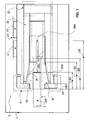
- holding device 1 for clamping a member 2 in a rotary apparatus 3 of a machine tool 4.
- the element 2 to hold by clamping may be a segment of a bar of material to be machined, but the term element 2 may also designate a machining tool having a portion of cylindrical shape for holding it by clamping (the latter case of a tool is not represented).
- the element 2 to be maintained is a cylindrical element of material to be machined, and, for example, a segment of a bar of material, or even a product already partially obtained by machining in such a bar segment.
- the element 2 to hold by clamping comprises a cylindrical gripping portion 20, this portion being delimited at least by a cylindrical radial face 201 and an end face 202.
- end face 202 which delimits longitudinally the cylindrical gripping portion 20 may be the end face of the element 2, but is not necessarily.
- the element 2 may extend well beyond the end face 202 by an outgrowth 200 of lesser cross section and, for example, as shown, by a single cylindrical stud.
- a rotary apparatus 3 of a machine tool 4 such as a machining tool-machine, consists of an elongated assembly, in particular a tubular assembly, which cooperates with rotation guiding means 41 and rotation drive means 42 supported by a stable assembly of this machine tool 4, such as the frame 43 of said machine tool 4.
- the clamp 10 is generally made of metal.
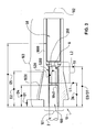
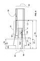
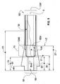
- the clamp 10 comprises at least one cutout 1000 of predetermined width L, which gives it a certain radial deformability at the level of the first span 1030, so that it is deformable between two states, on the one hand, the a contracted state in which the fourth face 104 is in an energetic support position around the cylindrical gripping portion 20 of an element 2 to be maintained, when the latter is engaged in the channel 100 over a fourth distance D4 and, on the other hand, on the other hand, the relaxed state in which said fourth face 104 is in a position away from said cylindrical gripping portion 20.
- Each cutout 1000 is of determined width L and extends from the first face 101 of the clamp 10 in the direction of the second face 102 of said clamp 10, and this, over a distance which, called the fifth distance D5, has a greater value. to the value of the second distance D2.
- this limit value of radial contraction can be zero.
- the seventh distance D7 separating the second longitudinal limit L2 from the first face 101 has a value greater than the second distance D2.
- the seventh distance D7 is substantially equal to the third distance D3.
- the cutouts 1000 constituted by the radial slots are three in number and are located in three planes arranged at angular intervals of one hundred twenty degrees (120 degrees).
- the first portion 51 of the second member 50 comprises at least one blade 501 made of a material resistant to compression and whose thickness E is adjusted according to the width of the cutouts 1000 so as to allow its insertion in one of these cutouts 1000.
- the first portion 51 of the second member 50 comprises as many blades 501 as 1000 cutouts provided in the clamp 10 and, to carry these blades 501, at least one part which, called first piece 510, is engaged in the channel 100 of this clamp 10.
- the standard clamps can therefore be used with the second member 50 made according to the first mode described above.
- the first part 510 comprises an axial passage 6 whose cross section is of suitable shape and size to allow the free engagement of a protrusion 200 of element 2 to maintain which extends beyond beyond the extreme face 202.
- the first portion 51 of the second member 50 comprises a cylindrical piece which, called second piece 520, is engaged in the channel 100 of the clamp 10 and has a peripheral support surface, which is called the first surface of support 5200, is intended to cooperate locally with the second reach 1040.
- the second piece 520 comprises an axial passage 6 whose cross section is of shape and of suitable dimensions to allow the free engagement of a protrusion 200 of element 2 to maintain that extends beyond the extreme face 202.
- the third piece 530 comprises an axial passage 6 whose cross section is at least equivalent to the cross section of the second bearing 1040.
- the second member 50 extends in the channel 100 of the clamp 10, substantially to the level of the second end face 102 of said clamp 10.
Landscapes
- Engineering & Computer Science (AREA)
- Mechanical Engineering (AREA)
- Jigs For Machine Tools (AREA)
- Diaphragms For Electromechanical Transducers (AREA)
- Grinding Of Cylindrical And Plane Surfaces (AREA)
- Clamps And Clips (AREA)
Claims (12)
- Haltevorrichtung (1) zum Halten durch Festklemmen eines Elements (2) in einem Drehgerät (3) einer Werkzeugmaschine (4), wobei das Element (2) zum Halten durch Festklemmen einen zylindrischen Greifteil (29) umfasst, wobei dieser Teil mindestens durch eine zylindrische radiale Fläche (201) und eine Außenfläche (202) begrenzt ist, wobei die Haltevorrichtung (1) umfasst:ein erstes längliches Organ, das, genannt Klammer (10),• äußerlich einerseits in der Längsrichtung durch zwei gegenüberliegende Außenflächen, genannt erste Fläche (101) und zweite Fläche (102), und, andererseits radial durch eine drehende Fläche, die, genannt dritte Fläche (103), mindestens einen Bereich mit konischer Form bildet, der, genannt erster Bereich (1030), sich einerseits zwischen zwei Distanzen erstreckt, die, messbar von der ersten Außenfläche (101), erste Distanz (D1) im Fall der kürzeren, und zweite Distanz (D2) im Fall der längeren, genannt werden, begrenzt ist und andererseits an der Zentrierung, der axialen Positionierung der Klammer (10) im Drehapparat (3) der Werkzeugmaschine (4) sowie an der Erzeugung eines Klemmvorgangs auf dem zu klemmenden Element (2) beitragen muss und• in der Längsrichtung von einem Kanal (100) durchquert wird, der von einer Fläche begrenzt ist, die, genannt vierte Fläche (104), mindestens einen Bereich mit zylindrischer Form bildet, der, genannt zweiter Bereich (1040), sich im Inneren des Kanals (100), von der ersten Fläche (101) der Klammer (10), auf einer vorbestimmten Distanz, genannt dritte Distanz (D3), gemessen von der ersten Fläche (101) aus erstreckt, und zum Halten durch Festklemmen von Element (2) beitragen muss.• mindestens einen Schnitt (1000) umfasst, der, mit einer bestimmten Länge (L) und sich von der ersten Fläche (101) der Klammer (10) in Richtung der zweiten Fläche (102) der Klammer (10) erstreckend auf einer Distanz, die, genannt fünfte Distanz (D5), einen Wert aufweist, der höher als der Wert der zweiten Distanz (D2) ist, der Klammer (10) eine bestimmte radiale Verformbarkeit auf der Ebene des ersten Bereichs (1030) verleiht, sodass sie zwischen zwei Zuständen verformbar ist, einerseits einem gespannten Zustand, in dem sich der zweite Bereich (1040) in einer Position der energischen Auflage um den zylindrischen Greifteil (20) eines Elementes (2) befindet, das in den Kanal (100) auf einer vorbestimmten Distanz, genannt vierte Distanz (D4), gemessen zwischen der Außenfläche (202) dieses Elementes (2) und der ersten Fläche (101) der Klammer (10) eingreift, und, andererseits, einem entspannten Zustand, in dem sich der zweite Bereich (1040) in einer Position befindet, in der vom zylindrischen Greifteil (20) entfernt ist.- ein funktionelles Betätigungselement (30) der Klammer zwischen den zwei Zuständen, d.h. dem gespannten Zustand und dem entspannten Zustand, und dies durch Anwendung von Spannungs- und Entspannungsmaßnahmen auf der Ebene des konischen Bereichs, genannt erster Bereich (1030), der sie enthält,wobei diese Vorrichtung dadurch gekennzeichnet ist, dass sie ein weiteres längliches Organ umfasst, das, genannt zweites Organ (50), sich in der Klammer (10) befindet und mindestens einen Teil umfasst, der, genannt erster Teil (51), vorgesehen ist, um die radiale Spannung der Klammer (10) auf einen vorbestimmten Wert zu begrenzen, und dies in einem Bereich, der sich zwischen folgendem erstreckt:- einer ersten länglichen Grenze (L1), die sich in einer Distanz von der ersten Fläche (101) der Klammer (10) befindet, die, genannt sechste Distanz (D6), einen Wert aufweist, der zwischen dem Wert der fünften Distanz (D5) und dem Wert der vierten Distanz (D4) liegt, und- einer zweiten länglichen Grenze (L2), die sich in einer anderen Distanz von der ersten Fläche (101) befindet, die, genannt siebte Distanz (D7), einen vorbestimmten Wert aufweist.
- Vorrichtung nach Anspruch 1, dadurch gekennzeichnet, dass die sechste Distanz (D6), die die erste längliche Grenze (L1) von der ersten Fläche (101) der Klammer (10) trennt, einen Wert aufweist, der geringer als der Wert der zweiten Distanz (D2) ist.
- Vorrichtung nach Anspruch 1 oder 2, dadurch gekennzeichnet, dass die siebte Distanz (D7), die die zweite Längsgrenze (L2) von der ersten Fläche (101) trennt, einen Wert aufweist, der größer als die zweite Distanz (D2) ist.
- Vorrichtung nach einem der Ansprüche 1 bis 3, dadurch gekennzeichnet, dass die siebte Distanz (D7) im Wesentlichen gleich der dritten Distanz (D3) ist.
- Vorrichtung nach einem der Ansprüche 1 bis 4, dadurch gekennzeichnet, dass der erste Teil (51) (51) des zweiten Organs (50) mindestens ein Blatt (501) umfasst, das aus einem Werkstoff besteht, der gegen die Verdichtung widerstandsfähig ist, und dessen Dicke (E) je nach der Breite der Schnitte (1000) angepasst ist, um seine Einfügung in einen dieser Schnitte (1000) zuzulassen.
- Vorrichtung nach Anspruch 5, dadurch gekennzeichnet, dass der erste Teil (51) des zweiten Organs (50) ebenso viele Blätter (501) wie Schnitte (1000) umfasst, die in der Klammer (10) vorgesehen sind und, um diese Blätter (501) zu tragen, mindestens ein Stück das, genannt erstes Stück (501), in den Kanal (100) dieser Klammer (10) eingreift.
- Vorrichtung nach einem der Ansprüche 1 bis 6, dadurch gekennzeichnet, dass das erste Stück (510) einen axiale Durchgang (6) umfasst, dessen Querschnitt eine Form und Abmessungen aufweist, die angemessen sind, um das freie Eingreifen eines Auswuchses (200) des zu haltenden Elements (2) zuzulassen, das sich über die Außenfläche (202) hinaus erstreckt.
- Vorrichtung nach einem der Ansprüche 1 bis 7, dadurch gekennzeichnet, dass der erste Teil (51) des zweiten Organs (50) mindestens ein zylindrisches Stück umfasst, das, genannt zweites Stück (520) in den Kanal (100) der Klammer (10) eingreift und eine periphere Stützfläche darstellt, die, genannt erste Stützfläche (5200), dazu vorgesehen ist, lokal mit dem zweiten Bereich (1040) zusammenzuarbeiten.
- Vorrichtung nach Anspruch 8, dadurch gekennzeichnet, dass das zweite Stück (520) einen axialen Durchgang (6) umfasst, dessen Querschnitt eine Form und Abmessungen aufweist, die angemessen sind, um das freie Eingreifen eines Auswuchses (200) des zu haltenden Elements (2) zuzulassen, das sich über die Außenseite (202) hinaus erstreckt.
- Vorrichtung nach einem der Ansprüche 1 bis 9, dadurch gekennzeichnet, dass der Kanal (100) der Klammer (10) einen Bereich umfasst, der, genannt vierter Bereich (1050), neben dem zweiten Bereich (1040) liegt und einen Querschnitt aufweist, der größer als derjenige des zweiten Bereichs (1040) ist, und- der erste Teil (51) des zweiten Organs (50) ein Stück umfasst, das, genannt drittes Stück (530), eine periphere Stützfläche darstellt, die, genannt zweite Stützfläche (5300), vorgesehen ist, um mit dem vierten Bereich (1050) so zusammenzuarbeiten, um eine Stutzfunktion dieses vierten Bereichs (1050) sicherzustellen, um die radiale Spannung der Klammer (10) auf einen vorbestimmten Wert zu beschränken.
- Vorrichtung nach Anspruch 10, dadurch gekennzeichnet, dass das dritte Stück (530) einen axialen Durchgang (6) umfasst, dessen Querschnitt mindestens gleich dem Querschnitt des zweiten Bereichs (1040) ist.
- Vorrichtung nach einem der Ansprüche 1 bis 11, dadurch gekennzeichnet, dass sich das zweite Organ im Kanal (100) der Klammer (10) erstreckt, im Wesentlichen bis zur Ebene der zweiten Fläche (102) der Klammer (10).
Priority Applications (3)
| Application Number | Priority Date | Filing Date | Title |
|---|---|---|---|
| DE602007006296T DE602007006296D1 (de) | 2007-06-26 | 2007-06-26 | Vorrichtung zum Halten mittels konischer Trageklammer mit kontrollierter Verformung |
| EP07111069A EP2008747B1 (de) | 2007-06-26 | 2007-06-26 | Vorrichtung zum Halten mittels konischer Trageklammer mit kontrollierter Verformung |
| AT07111069T ATE466682T1 (de) | 2007-06-26 | 2007-06-26 | Vorrichtung zum halten mittels konischer trageklammer mit kontrollierter verformung |
Applications Claiming Priority (1)
| Application Number | Priority Date | Filing Date | Title |
|---|---|---|---|
| EP07111069A EP2008747B1 (de) | 2007-06-26 | 2007-06-26 | Vorrichtung zum Halten mittels konischer Trageklammer mit kontrollierter Verformung |
Publications (2)
| Publication Number | Publication Date |
|---|---|
| EP2008747A1 EP2008747A1 (de) | 2008-12-31 |
| EP2008747B1 true EP2008747B1 (de) | 2010-05-05 |
Family
ID=38720567
Family Applications (1)
| Application Number | Title | Priority Date | Filing Date |
|---|---|---|---|
| EP07111069A Active EP2008747B1 (de) | 2007-06-26 | 2007-06-26 | Vorrichtung zum Halten mittels konischer Trageklammer mit kontrollierter Verformung |
Country Status (3)
| Country | Link |
|---|---|
| EP (1) | EP2008747B1 (de) |
| AT (1) | ATE466682T1 (de) |
| DE (1) | DE602007006296D1 (de) |
Family Cites Families (4)
| Publication number | Priority date | Publication date | Assignee | Title |
|---|---|---|---|---|
| US3041078A (en) * | 1959-12-14 | 1962-06-26 | Robert E Curran | Stock stop for collets |
| DE59309072D1 (de) * | 1992-01-23 | 1998-11-26 | Hansjuerg Moser | Spannzangenanschlag |
| US6280126B1 (en) * | 1999-09-23 | 2001-08-28 | Aesop, Inc. | Damped tool holder and method |
| US6371705B1 (en) * | 2000-09-22 | 2002-04-16 | Fl Toolholders, Inc. | Tool holder |
-
2007
- 2007-06-26 AT AT07111069T patent/ATE466682T1/de not_active IP Right Cessation
- 2007-06-26 EP EP07111069A patent/EP2008747B1/de active Active
- 2007-06-26 DE DE602007006296T patent/DE602007006296D1/de active Active
Also Published As
| Publication number | Publication date |
|---|---|
| EP2008747A1 (de) | 2008-12-31 |
| ATE466682T1 (de) | 2010-05-15 |
| DE602007006296D1 (de) | 2010-06-17 |
Similar Documents
| Publication | Publication Date | Title |
|---|---|---|
| EP2183491B1 (de) | Vorrichtung zum anordnen von einem klemmring auf einem teil und automatisch ausgelöstes klemmsystem mit einer solchen vorrichtung | |
| EP3482700B1 (de) | Schädelbohrer | |
| FR2549547A1 (fr) | Procede et dispositif de fixation de pieces mecaniques | |
| EP0281511B1 (de) | Drahtschneidevorrichtung | |
| BE1017946A3 (fr) | Procede et dispositif pour fabriquer des brosses. | |
| FR2920922A1 (fr) | Jeu d'instruments pour le retrait de la gaine en plomb d'un cable electrique. | |
| WO2011101592A2 (fr) | Aiguille pour l'insertion d'un fil dans un pneumatique | |
| EP2576112B1 (de) | Verfahren zur bearbeitung von hohlräumen in einer turbomaschinenturbinenscheibe | |
| EP2008747A1 (de) | Vorrichtung zum Halten mittels konischer Trageklammer mit kontrollierter Verformung | |
| EP0375530A1 (de) | Kabelentmantelungswerkzeug, namentlich von aufgebauten Kabeln | |
| EP3801963B1 (de) | Station zum automatisierten sägen von radfelgen für fahrräder | |
| EP1787370B1 (de) | Vorrichtung zum abziehen eines wickelkörpers, besonders eines kabels mit mehreren konzentrischen schichten und scheidwerkzeug für solch eine vorrichtung | |
| FR2786122A1 (fr) | Scie cloche a deux niveaux, pour le faconnage d'un logement dans une cloison seche | |
| EP3144742B1 (de) | Mikroregulierung der unruhträgheit eines uhrwerks | |
| FR2554747A1 (fr) | Outil pour le tronconnage de tubes | |
| EP0952898B1 (de) | Rohrschneidvorrichtung | |
| EP1533059B1 (de) | Elastische Einrichtung für elastisches Stützgerät für ein Werkstück | |
| EP1762319B1 (de) | Verfahren zur Optimierung der Funktion einer Werkzeugmachine mit einer zusätzlichen Stangenführungseinrichtung und entsprechende Werkzeugmaschine | |
| EP1977844B1 (de) | Vorrichtung zum Innenentgraten von Rohren | |
| FR3073776A1 (fr) | Porte-gomme pour crayon et ensemble d'un crayon, d'une gomme et d'un porte-gomme | |
| WO2025214605A1 (fr) | Pince de serrage pour machine-outil | |
| EP1054759B1 (de) | Abfallausbrechvorrichtung für gestanzte kartonagen | |
| FR2774889A1 (fr) | Dispositif pour fixer un fil de suture a une aiguille chirurgicale | |
| FR2914574A1 (fr) | Dispositif de coupe ou de recoupe de tubes muni d'un couteau interieur | |
| FR2824919A1 (fr) | Dispositif d'ouverture de gaine mince de module de fibres optiques |
Legal Events
| Date | Code | Title | Description |
|---|---|---|---|
| PUAI | Public reference made under article 153(3) epc to a published international application that has entered the european phase |
Free format text: ORIGINAL CODE: 0009012 |
|
| AK | Designated contracting states |
Kind code of ref document: A1 Designated state(s): AT BE BG CH CY CZ DE DK EE ES FI FR GB GR HU IE IS IT LI LT LU LV MC MT NL PL PT RO SE SI SK TR |
|
| AX | Request for extension of the european patent |
Extension state: AL BA HR MK RS |
|
| 17P | Request for examination filed |
Effective date: 20090502 |
|
| AKX | Designation fees paid |
Designated state(s): AT BE BG CH CY CZ DE DK EE ES FI FR GB GR HU IE IS IT LI LT LU LV MC MT NL PL PT RO SE SI SK TR |
|
| GRAP | Despatch of communication of intention to grant a patent |
Free format text: ORIGINAL CODE: EPIDOSNIGR1 |
|
| GRAS | Grant fee paid |
Free format text: ORIGINAL CODE: EPIDOSNIGR3 |
|
| GRAA | (expected) grant |
Free format text: ORIGINAL CODE: 0009210 |
|
| AK | Designated contracting states |
Kind code of ref document: B1 Designated state(s): AT BE BG CH CY CZ DE DK EE ES FI FR GB GR HU IE IS IT LI LT LU LV MC MT NL PL PT RO SE SI SK TR |
|
| REG | Reference to a national code |
Ref country code: GB Ref legal event code: FG4D Free format text: NOT ENGLISH |
|
| REG | Reference to a national code |
Ref country code: CH Ref legal event code: NV Representative=s name: BOVARD AG PATENTANWAELTE Ref country code: CH Ref legal event code: EP |
|
| REG | Reference to a national code |
Ref country code: IE Ref legal event code: FG4D Free format text: LANGUAGE OF EP DOCUMENT: FRENCH |
|
| REF | Corresponds to: |
Ref document number: 602007006296 Country of ref document: DE Date of ref document: 20100617 Kind code of ref document: P |
|
| REG | Reference to a national code |
Ref country code: NL Ref legal event code: VDEP Effective date: 20100505 |
|
| LTIE | Lt: invalidation of european patent or patent extension |
Effective date: 20100505 |
|
| PG25 | Lapsed in a contracting state [announced via postgrant information from national office to epo] |
Ref country code: SE Free format text: LAPSE BECAUSE OF FAILURE TO SUBMIT A TRANSLATION OF THE DESCRIPTION OR TO PAY THE FEE WITHIN THE PRESCRIBED TIME-LIMIT Effective date: 20100505 Ref country code: ES Free format text: LAPSE BECAUSE OF FAILURE TO SUBMIT A TRANSLATION OF THE DESCRIPTION OR TO PAY THE FEE WITHIN THE PRESCRIBED TIME-LIMIT Effective date: 20100816 Ref country code: LT Free format text: LAPSE BECAUSE OF FAILURE TO SUBMIT A TRANSLATION OF THE DESCRIPTION OR TO PAY THE FEE WITHIN THE PRESCRIBED TIME-LIMIT Effective date: 20100505 Ref country code: NL Free format text: LAPSE BECAUSE OF FAILURE TO SUBMIT A TRANSLATION OF THE DESCRIPTION OR TO PAY THE FEE WITHIN THE PRESCRIBED TIME-LIMIT Effective date: 20100505 |
|
| PG25 | Lapsed in a contracting state [announced via postgrant information from national office to epo] |
Ref country code: FI Free format text: LAPSE BECAUSE OF FAILURE TO SUBMIT A TRANSLATION OF THE DESCRIPTION OR TO PAY THE FEE WITHIN THE PRESCRIBED TIME-LIMIT Effective date: 20100505 Ref country code: SI Free format text: LAPSE BECAUSE OF FAILURE TO SUBMIT A TRANSLATION OF THE DESCRIPTION OR TO PAY THE FEE WITHIN THE PRESCRIBED TIME-LIMIT Effective date: 20100505 Ref country code: LV Free format text: LAPSE BECAUSE OF FAILURE TO SUBMIT A TRANSLATION OF THE DESCRIPTION OR TO PAY THE FEE WITHIN THE PRESCRIBED TIME-LIMIT Effective date: 20100505 Ref country code: AT Free format text: LAPSE BECAUSE OF FAILURE TO SUBMIT A TRANSLATION OF THE DESCRIPTION OR TO PAY THE FEE WITHIN THE PRESCRIBED TIME-LIMIT Effective date: 20100505 Ref country code: IS Free format text: LAPSE BECAUSE OF FAILURE TO SUBMIT A TRANSLATION OF THE DESCRIPTION OR TO PAY THE FEE WITHIN THE PRESCRIBED TIME-LIMIT Effective date: 20100905 |
|
| REG | Reference to a national code |
Ref country code: IE Ref legal event code: FD4D |
|
| BERE | Be: lapsed |
Owner name: TORNOS SA Effective date: 20100630 |
|
| PG25 | Lapsed in a contracting state [announced via postgrant information from national office to epo] |
Ref country code: CY Free format text: LAPSE BECAUSE OF FAILURE TO SUBMIT A TRANSLATION OF THE DESCRIPTION OR TO PAY THE FEE WITHIN THE PRESCRIBED TIME-LIMIT Effective date: 20100609 Ref country code: PL Free format text: LAPSE BECAUSE OF FAILURE TO SUBMIT A TRANSLATION OF THE DESCRIPTION OR TO PAY THE FEE WITHIN THE PRESCRIBED TIME-LIMIT Effective date: 20100505 |
|
| PG25 | Lapsed in a contracting state [announced via postgrant information from national office to epo] |
Ref country code: DK Free format text: LAPSE BECAUSE OF FAILURE TO SUBMIT A TRANSLATION OF THE DESCRIPTION OR TO PAY THE FEE WITHIN THE PRESCRIBED TIME-LIMIT Effective date: 20100505 Ref country code: PT Free format text: LAPSE BECAUSE OF FAILURE TO SUBMIT A TRANSLATION OF THE DESCRIPTION OR TO PAY THE FEE WITHIN THE PRESCRIBED TIME-LIMIT Effective date: 20100906 Ref country code: EE Free format text: LAPSE BECAUSE OF FAILURE TO SUBMIT A TRANSLATION OF THE DESCRIPTION OR TO PAY THE FEE WITHIN THE PRESCRIBED TIME-LIMIT Effective date: 20100505 Ref country code: MC Free format text: LAPSE BECAUSE OF NON-PAYMENT OF DUE FEES Effective date: 20100630 Ref country code: IE Free format text: LAPSE BECAUSE OF FAILURE TO SUBMIT A TRANSLATION OF THE DESCRIPTION OR TO PAY THE FEE WITHIN THE PRESCRIBED TIME-LIMIT Effective date: 20100505 |
|
| PG25 | Lapsed in a contracting state [announced via postgrant information from national office to epo] |
Ref country code: SK Free format text: LAPSE BECAUSE OF FAILURE TO SUBMIT A TRANSLATION OF THE DESCRIPTION OR TO PAY THE FEE WITHIN THE PRESCRIBED TIME-LIMIT Effective date: 20100505 Ref country code: CZ Free format text: LAPSE BECAUSE OF FAILURE TO SUBMIT A TRANSLATION OF THE DESCRIPTION OR TO PAY THE FEE WITHIN THE PRESCRIBED TIME-LIMIT Effective date: 20100505 Ref country code: RO Free format text: LAPSE BECAUSE OF FAILURE TO SUBMIT A TRANSLATION OF THE DESCRIPTION OR TO PAY THE FEE WITHIN THE PRESCRIBED TIME-LIMIT Effective date: 20100505 |
|
| PLBE | No opposition filed within time limit |
Free format text: ORIGINAL CODE: 0009261 |
|
| STAA | Information on the status of an ep patent application or granted ep patent |
Free format text: STATUS: NO OPPOSITION FILED WITHIN TIME LIMIT |
|
| REG | Reference to a national code |
Ref country code: CH Ref legal event code: PFA Owner name: TORNOS SA Free format text: TORNOS SA#RUE INDUSTRIELLE 111#2740 MOUTIER (CH) -TRANSFER TO- TORNOS SA#RUE INDUSTRIELLE 111#2740 MOUTIER (CH) |
|
| 26N | No opposition filed |
Effective date: 20110208 |
|
| PG25 | Lapsed in a contracting state [announced via postgrant information from national office to epo] |
Ref country code: GR Free format text: LAPSE BECAUSE OF FAILURE TO SUBMIT A TRANSLATION OF THE DESCRIPTION OR TO PAY THE FEE WITHIN THE PRESCRIBED TIME-LIMIT Effective date: 20100806 Ref country code: MT Free format text: LAPSE BECAUSE OF FAILURE TO SUBMIT A TRANSLATION OF THE DESCRIPTION OR TO PAY THE FEE WITHIN THE PRESCRIBED TIME-LIMIT Effective date: 20100505 |
|
| REG | Reference to a national code |
Ref country code: DE Ref legal event code: R097 Ref document number: 602007006296 Country of ref document: DE Effective date: 20110207 |
|
| PG25 | Lapsed in a contracting state [announced via postgrant information from national office to epo] |
Ref country code: BE Free format text: LAPSE BECAUSE OF NON-PAYMENT OF DUE FEES Effective date: 20100630 |
|
| PG25 | Lapsed in a contracting state [announced via postgrant information from national office to epo] |
Ref country code: BG Free format text: LAPSE BECAUSE OF FAILURE TO SUBMIT A TRANSLATION OF THE DESCRIPTION OR TO PAY THE FEE WITHIN THE PRESCRIBED TIME-LIMIT Effective date: 20100505 Ref country code: HU Free format text: LAPSE BECAUSE OF FAILURE TO SUBMIT A TRANSLATION OF THE DESCRIPTION OR TO PAY THE FEE WITHIN THE PRESCRIBED TIME-LIMIT Effective date: 20101106 Ref country code: LU Free format text: LAPSE BECAUSE OF NON-PAYMENT OF DUE FEES Effective date: 20100626 |
|
| PG25 | Lapsed in a contracting state [announced via postgrant information from national office to epo] |
Ref country code: TR Free format text: LAPSE BECAUSE OF FAILURE TO SUBMIT A TRANSLATION OF THE DESCRIPTION OR TO PAY THE FEE WITHIN THE PRESCRIBED TIME-LIMIT Effective date: 20100505 |
|
| PGFP | Annual fee paid to national office [announced via postgrant information from national office to epo] |
Ref country code: GB Payment date: 20130619 Year of fee payment: 7 |
|
| PG25 | Lapsed in a contracting state [announced via postgrant information from national office to epo] |
Ref country code: BG Free format text: LAPSE BECAUSE OF FAILURE TO SUBMIT A TRANSLATION OF THE DESCRIPTION OR TO PAY THE FEE WITHIN THE PRESCRIBED TIME-LIMIT Effective date: 20100805 |
|
| GBPC | Gb: european patent ceased through non-payment of renewal fee |
Effective date: 20140626 |
|
| PG25 | Lapsed in a contracting state [announced via postgrant information from national office to epo] |
Ref country code: GB Free format text: LAPSE BECAUSE OF NON-PAYMENT OF DUE FEES Effective date: 20140626 |
|
| REG | Reference to a national code |
Ref country code: FR Ref legal event code: PLFP Year of fee payment: 10 |
|
| REG | Reference to a national code |
Ref country code: FR Ref legal event code: PLFP Year of fee payment: 11 |
|
| REG | Reference to a national code |
Ref country code: FR Ref legal event code: PLFP Year of fee payment: 12 |
|
| PGFP | Annual fee paid to national office [announced via postgrant information from national office to epo] |
Ref country code: FR Payment date: 20220628 Year of fee payment: 16 |
|
| PGFP | Annual fee paid to national office [announced via postgrant information from national office to epo] |
Ref country code: CH Payment date: 20220613 Year of fee payment: 16 |
|
| PGFP | Annual fee paid to national office [announced via postgrant information from national office to epo] |
Ref country code: DE Payment date: 20230620 Year of fee payment: 17 |
|
| P01 | Opt-out of the competence of the unified patent court (upc) registered |
Effective date: 20230630 |
|
| PGFP | Annual fee paid to national office [announced via postgrant information from national office to epo] |
Ref country code: IT Payment date: 20230621 Year of fee payment: 17 |
|
| REG | Reference to a national code |
Ref country code: CH Ref legal event code: PL |
|
| PG25 | Lapsed in a contracting state [announced via postgrant information from national office to epo] |
Ref country code: CH Free format text: LAPSE BECAUSE OF NON-PAYMENT OF DUE FEES Effective date: 20230630 |
|
| PG25 | Lapsed in a contracting state [announced via postgrant information from national office to epo] |
Ref country code: FR Free format text: LAPSE BECAUSE OF NON-PAYMENT OF DUE FEES Effective date: 20230630 |
|
| REG | Reference to a national code |
Ref country code: DE Ref legal event code: R119 Ref document number: 602007006296 Country of ref document: DE |
|
| PG25 | Lapsed in a contracting state [announced via postgrant information from national office to epo] |
Ref country code: DE Free format text: LAPSE BECAUSE OF NON-PAYMENT OF DUE FEES Effective date: 20250101 |