EP2008635A2 - Computergesteuertes Hydrotherapiesystem - Google Patents
Computergesteuertes Hydrotherapiesystem Download PDFInfo
- Publication number
- EP2008635A2 EP2008635A2 EP08010682A EP08010682A EP2008635A2 EP 2008635 A2 EP2008635 A2 EP 2008635A2 EP 08010682 A EP08010682 A EP 08010682A EP 08010682 A EP08010682 A EP 08010682A EP 2008635 A2 EP2008635 A2 EP 2008635A2
- Authority
- EP
- European Patent Office
- Prior art keywords
- water
- temperature
- body zone
- hydrotherapy
- solenoid valves
- Prior art date
- Legal status (The legal status is an assumption and is not a legal conclusion. Google has not performed a legal analysis and makes no representation as to the accuracy of the status listed.)
- Granted
Links
- 238000002169 hydrotherapy Methods 0.000 title claims abstract description 38
- XLYOFNOQVPJJNP-UHFFFAOYSA-N water Substances O XLYOFNOQVPJJNP-UHFFFAOYSA-N 0.000 claims abstract description 118
- 230000002123 temporal effect Effects 0.000 claims description 11
- 238000000034 method Methods 0.000 claims description 10
- 230000002452 interceptive effect Effects 0.000 claims description 3
- 238000005259 measurement Methods 0.000 claims description 3
- 230000004044 response Effects 0.000 claims description 3
- 230000008859 change Effects 0.000 claims description 2
- 230000004048 modification Effects 0.000 description 7
- 238000012986 modification Methods 0.000 description 7
- 238000010586 diagram Methods 0.000 description 6
- 238000002560 therapeutic procedure Methods 0.000 description 6
- 230000005540 biological transmission Effects 0.000 description 5
- 230000000694 effects Effects 0.000 description 4
- 230000001225 therapeutic effect Effects 0.000 description 4
- 238000005516 engineering process Methods 0.000 description 3
- 230000003287 optical effect Effects 0.000 description 3
- 230000009471 action Effects 0.000 description 2
- 230000009286 beneficial effect Effects 0.000 description 2
- 238000004891 communication Methods 0.000 description 2
- 230000035876 healing Effects 0.000 description 2
- 238000012423 maintenance Methods 0.000 description 2
- 238000012806 monitoring device Methods 0.000 description 2
- 230000008569 process Effects 0.000 description 2
- 210000003813 thumb Anatomy 0.000 description 2
- 241000276498 Pollachius virens Species 0.000 description 1
- 230000033228 biological regulation Effects 0.000 description 1
- 230000017531 blood circulation Effects 0.000 description 1
- 230000036760 body temperature Effects 0.000 description 1
- 210000004556 brain Anatomy 0.000 description 1
- 230000004087 circulation Effects 0.000 description 1
- 238000004590 computer program Methods 0.000 description 1
- 238000010276 construction Methods 0.000 description 1
- 230000029087 digestion Effects 0.000 description 1
- 201000010099 disease Diseases 0.000 description 1
- 208000037265 diseases, disorders, signs and symptoms Diseases 0.000 description 1
- 210000000987 immune system Anatomy 0.000 description 1
- 239000004615 ingredient Substances 0.000 description 1
- 238000009434 installation Methods 0.000 description 1
- 238000004519 manufacturing process Methods 0.000 description 1
- 239000000203 mixture Substances 0.000 description 1
- 210000005036 nerve Anatomy 0.000 description 1
- 230000008533 pain sensitivity Effects 0.000 description 1
- 238000009428 plumbing Methods 0.000 description 1
- 238000003825 pressing Methods 0.000 description 1
- 238000011112 process operation Methods 0.000 description 1
- 230000009467 reduction Effects 0.000 description 1
- 239000004065 semiconductor Substances 0.000 description 1
- 230000035807 sensation Effects 0.000 description 1
- 229910052709 silver Inorganic materials 0.000 description 1
- 239000004332 silver Substances 0.000 description 1
- 230000004936 stimulating effect Effects 0.000 description 1
- 239000002438 stress hormone Substances 0.000 description 1
- 230000001629 suppression Effects 0.000 description 1
- 230000002277 temperature effect Effects 0.000 description 1
- 230000000699 topical effect Effects 0.000 description 1
- 238000012549 training Methods 0.000 description 1
Images


Classifications
-
- A—HUMAN NECESSITIES
- A61—MEDICAL OR VETERINARY SCIENCE; HYGIENE
- A61H—PHYSICAL THERAPY APPARATUS, e.g. DEVICES FOR LOCATING OR STIMULATING REFLEX POINTS IN THE BODY; ARTIFICIAL RESPIRATION; MASSAGE; BATHING DEVICES FOR SPECIAL THERAPEUTIC OR HYGIENIC PURPOSES OR SPECIFIC PARTS OF THE BODY
- A61H33/00—Bathing devices for special therapeutic or hygienic purposes
- A61H33/005—Electrical circuits therefor
-
- A—HUMAN NECESSITIES
- A61—MEDICAL OR VETERINARY SCIENCE; HYGIENE
- A61H—PHYSICAL THERAPY APPARATUS, e.g. DEVICES FOR LOCATING OR STIMULATING REFLEX POINTS IN THE BODY; ARTIFICIAL RESPIRATION; MASSAGE; BATHING DEVICES FOR SPECIAL THERAPEUTIC OR HYGIENIC PURPOSES OR SPECIFIC PARTS OF THE BODY
- A61H2201/00—Characteristics of apparatus not provided for in the preceding codes
- A61H2201/50—Control means thereof
- A61H2201/5007—Control means thereof computer controlled
Definitions
- This invention relates to hydrotherapy and hydrothermal therapy systems and particularly to computer-controlled hydrotherapy systems.
- Hydrotherapy is the use of water for treatment of disease, stress reduction and recuperation.
- Hydrothermal therapy additionally uses the temperature effects of water, for example in hot baths, saunas and wraps.
- hydrotherapy and hydrothermal therapy will be referred to collectively as hydrotherapy below.
- Hydrotherapy is a traditional method of treatment that has been used by many cultures, including those of ancient Rome, Greece, China, and Japan for centuries. Water is also an important ingredient in Chinese and Native American healing traditions. However, a Bavarian monk, Father Sebastian Kneipp, is credited with re-popularizing the therapeutic use of water in the 19th century in Europe. There are now many dozens of methods of applying hydrotherapy, including baths, showers, saunas, douches, wraps, and packs.
- recuperative and healing properties of hydrotherapy are based on the mechanical and thermal effects of the water and exploit a bodily reaction to hot and cold stimuli, to the protracted application of heat, to pressure exerted by the water and to the resulting sensation. It is thought that the nerves carry impulses felt at the skin deeper into the body, where they are instrumental in stimulating the immune system, influencing the production of stress hormones, invigorating the circulation and digestion, encouraging blood flow, and lessening pain sensitivity.
- a computer controls valves that can modify both the temperature and pressure of the water streams applied to different body zones.
- the system uses servo-controlled valves, such as those disclosed in U.S. Patent No. 5,050,062 .
- Each valve receives both hot and cold water from separate supplies and mixes the hot and cold water via a mixing valve controlled by a stepper motor.
- the valve also includes a temperature sensor which is monitored by a computer.
- the computer controls the stepper motor to change the hot and cold water mixture to bring the actual temperature to the set-point temperature. Therefore, the water temperature delivered by the valves can be adjusted to any given temperature between the temperatures of the hot and cold water supplies and the flow rate is also continuously adjustable
- a hydrotherapy system uses a plurality of water sources, each of which produces water at a temperature that is fixed during a particular hydrotherapy session.
- the water from the fixed temperature sources can be mixed to form several mixed water streams, each with a predetermined temperature, by an array of computer-controlled on-off solenoid valves.
- Solenoid valves can also be used to apply the mixed water streams with different flow rates selectively to different zones and, thence, to different body areas. Since the solenoid valves are relatively uncomplicated and readily available, they are much less expensive, and require much less maintenance, than custom mixing valves.
- conventional mechanical thermostatic mixing valves are used to provide fixed temperature water sources.
- the solenoid valves are controlled by a microcontroller.
- a graphical user interface can be used to quickly program complex sequences of water temperature and body location.
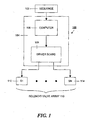
- FIG. 1 is a block schematic diagram of a hydrotherapy shower system constructed in accordance with the principles of the invention.
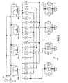
- Figure 2 is a schematic diagram that shows an illustrative valve configuration and piping diagram using four fixed temperature sources.
- Figure 3 is a schematic diagram of a set of sequence words that generate an illustrative sequence of water streams with predetermined temperatures and flows.
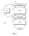
- Figure 4 is a block schematic diagram that shows a control system for controlling the solenoid array based on the sequence shown in Figure 3 .
- Figure 5 is a screen shot showing a graphical user interface that can be used to generate the sequence words shown in Figure 3 .
- Figure 6 is a screen shot showing the graphical user interface shown in Figure 5 with a control window open that allows the flow rate to be set for a particular time period and body zone.
- Figure 7 is a schematic diagram illustrating a modification of a sequence during a hydrotherapy session in response to external information, such as inputs generated by monitoring devices to inputs generated by user actions.
- FIG. 1 shows the overall architecture 100 of a computerized hydrotherapy system constructed in accordance with the principles of the present invention.
- a sequence 102 which controls the pattern and timing of valve operation and is described in detail below, drives a controller 104.
- the controller 104 opens or closes the solenoid valves in the solenoid valve array 110 in the pattern directed by the sequence.
- the controller 104 can be implemented with a number of conventional architectures.
- the controller can comprise a computer 106 that might, illustratively, be a personal computer that operates with a "touch screen" interface.
- the computer 106 controls a driver board 108 with a plurality of outputs, each of which can drive one of the solenoid valves in solenoid valve array 110.
- the controller 104 might comprise a microcontroller that operates with a button array interface. The microcontroller can, in turn, operate the driver board that controls the solenoid valves in array 110.
- Each solenoid valve such as valve 112 or 114, is an on-off valve which is either fully open or fully closed.
- Such valves have a relatively simple construction, are easy to maintain and readily-available.
- solenoid valves that operate on a low voltage, typically 24 AC volts, are commonly used in fire suppression systems and are relatively inexpensive.
- An example of such a valve is a Danfoss EVSI 15-50B. Similar valves are used in underground lawn sprinkler systems and these are also suitable for use with the invention.
- the same therapeutic effects can also be achieved by mixing the output streams from a plurality of fixed-temperature water sources to form a fixed number of water streams with predetermined temperatures and by using a predetermined number of fixed flow rates.
- the solenoid valves in the array 108 are connected, via piping, between water sources whose temperatures are fixed during a particular therapeutic sequence and the water delivery jets. By opening and closing the valves in various patterns, selected water sources can be connected to selected jets in order to provide simultaneous water streams of various temperatures and flow rates to several body zones.
- An illustrative solenoid valve array and piping arrangement is shown in Figure 2 .
- the array 200 connects four fixed-temperature water sources 202-208 to four body zones 210-216 and is comprised of a plurality of normally-closed solenoid valves S1 - S28 connected together by pipes that are represented in Figure 2 by lines. Although four water sources and four body zones are shown for illustrative purposes, those skilled in the art would understand that more or fewer water sources could be used and more or fewer body zones could also be used without departing from the spirit and scope of the invention.
- Each of the fixed-temperature water sources 202-208 receives hot water from a hot water supply 220 and cold water from a cold water supply 222.
- the hot water supply may be approximately at a temperature of 120 degrees Fahrenheit and the cold water can be at an ambient cold water temperature, for example 55 degrees Fahrenheit, although other water temperatures could also be used.
- each of water sources 202-208 comprises an adjustable thermostatic mixing valve such as a Honeywell Sparco model AM 101C-US-1 manufactured and sold by Honeywell Controls, Inc.
- Such a valve mechanically adjusts the hot and cold water flows to produce an output water stream at a temperature intermediate between the hot and cold temperatures.
- the output temperature is typically determined by manually manipulating an adjustment knob. Once the output temperature has been set, the valve will maintain that temperature within a predetermined range. The use of such valves is advantageous because they are already required by many local building codes and regulations.
- motorized mixing valves could also be used. These valves use a small motor to adjust the hot and cold water flows to produce an output water stream at a temperature intermediate between the hot and cold temperatures. Such valves would allow the temperature of the supplies to be changed between sequences, but the temperature would remain fixed during the execution of a particular therapeutic sequence.
- Each of the water sources 202-208 is set to a different predetermined temperature. As shown, for example, source 202 is set to 70 degrees Fahrenheit, source 204 is set to 98 degrees Fahrenheit, source 206 is set to 106 degrees Fahrenheit and source 208 is set to 110 degrees Fahrenheit. In other embodiments, other temperatures could also be used depending on the type of therapy that is desired.
- Each of the sources 202-208 can be connected to a zone by opening one of solenoid valves S1-S16 to each of zones 210-216.
- opening solenoid valve S1 connects 70°F water from source 202 to zone 1 (210).
- opening solenoid valve S2 connects 70°F water from source 202 to zone 2 (213).
- Opening solenoid valve S3 connects 70°F water from source 202 to zone 3 (214).
- opening solenoid valve S4 connects 70°F water from source 202 to zone 4 (216).
- opening valve S5 connects 98°F water from source 204 to zone 1 (210). etc.
- opening two valves simultaneously directs water from two sources to a single zone.
- the water stream arriving at the zone has a temperature that is approximately the average of the water temperatures of the two sources.
- opening both valve S1 and valve S5 produces an output water stream that is applied to zone 1 (210) and has a temperature of 84°F that is the average (70 + 98)/2 of the temperatures of the two water sources 202 and 204.
- opening three valves, such as valves S1, S5 and S9 from three different water sources 202, 204 and 206 produces an output water stream that is applied to zone 1 (210) with a temperature of 91.3°F (70 + 98 + 106)/3.
- zones 1-4 210-216) 70, 84, 88, 90, 91.3, 92.7, 95.3, 96, 98, 102, 104, 104.7, 106, 108 and 110.
- each zone has a plurality of solenoid valves connected in parallel.
- each zone has three solenoid valves connected in parallel.
- solenoid valves can be used to control the water flow rate for each zone.
- the water flow rate for zone 1 (210) can be increased by simultaneously opening one, two or all of valves 517, S18 and S19.
- valves S20, S21 and S22 control the flow rate for zone 2 (212); valves S23, S24 and S25 control the flow rate for zone 3 (21a) and valves S26, S27 and S28 control the flow rate for zone 4 (216).
- Figure 3 shows an illustrative sequence 300 for controlling the solenoid array 200 to produce a specified temporal sequence of water streams.
- the sequence 300 consists of a plurality of time periods, each of fixed length in this embodiment.
- the sequence 300 consists of six time periods.
- each time period may be subdivided into shorter time intervals of fixed duration, for example, five seconds.
- the shorter time intervals allow time periods of different duration to be constructed.
- time periods can be constructed with time durations of five seconds, ten seconds, fifteen seconds, twenty seconds, etc.
- each illustrative time period in Figure 3 is comprised of two time intervals and consequently, would be ten seconds in duration. With this arrangement, the entire sequence 300, which is comprised of six time periods, would be one minute in length.
- Each time interval is associated with a sequence word containing a plurality of bits, with each bit associated with one of the solenoids in array 200.
- the first time interval of period 1 is associated with word 302 and the second time interval is associated with word 304.
- Each of words 302 and 304 contains 28 bits with each bit corresponding to one of the 28 solenoids in Figure 2 as marked at the top of Figure 3 .
- Each sequence word controls the solenoid array for an entire time interval. When a particular bit is set to a "1", the associated valve will be open allowing water to flow through it for the entire time interval. When the bit is set to a "0”, the valve will be closed and no water will pass through in the associated time interval. If more than one time interval is used to construct a time period, then the sequence words associated with each time interval in the time period will hold the identical pattern of "1"s and "0"s so that each solenoid will remain open or closed for the entire time period.
- bits 11 and 23 remain set to "1", but bits 7 and 15 are set to "0" causing the associated solenoids to open, or close, their valves. Comparing this pattern to the solenoid array in Figure 2 shows that, with solenoids S11 and S23 operating, water from source 206 with a temperature of 106 degrees is applied at a low flow rate (only one valve S23 open) to body zone 3.
- bits 5, 9, 17 and 18 remain set to "1" is causing the associated solenoids to open their valves.
- water from sources 204 and 206 with a temperature of 102 degrees continues to be applied at a medium flow rate to body zone 1.
- This pattern also persists in time periods 5 and 6.
- bits 11 and 23 are set to "0" causing the water stream that was being applied to body zone 3 to stop. This pattern also persists in time periods 5 and 6.
- bits 4, 8, 12, 26, 27 and 28 are set to "1"s causing the associated solenoids to open their valves.
- the solenoids could be controlled by sequences that specify the open and close time of each sequence.
- the time intervals during which the solenoids are open or closed need not be fixed, or equal, in duration.
- Figure 4 shows an illustrative system 400 for controlling the valve array shown in Figure 2 with the sequence shown in Figure 3 .
- sequence words such as those shown in Figure 3 are loaded into memory 412 at the start of a sequence.
- a timer 402 generates a time signal at the beginning of each time interval. This time signal is applied, as indicated schematically by arrow 404, to an address counter 408.
- the signal causes the counter 408 to generate a new set of address signals 410 that are applied to memory 412.
- the address signals cause the sequence word for that time interval to be read out of the memory 412 and to appear on memory outputs 414.
- the bits of the sequence word are latched into an output register 416 by another signal (indicated schematically by arrow 406) from timer 402.
- Outputs 418 of register 416 are applied to drivers 420 that provide the signals to operate the solenoids in the solenoid array 422.
- Sequences such as that illustrated in Figure 3 can be manually built by setting the bits in each sequence word in memory 412. Such a process is tedious and time-consuming.
- sequences can be built via an interactive graphical user interface generated by a program.
- This program could be running on a computer operated by the user or, alternatively, the program could be running on a web server and accessed by the user remotely via a conventional web browser.
- Illustrative display screens generated by an interface of this type are shown in Figures 5 and 6 . These screens are interactive in that they can be manipulated with a pointing device, such as a mouse.
- Figure 5 illustrates a display 500 for constructing sequences for a hydrotherapy system which has six body zones (zone 502 - "Overhead”, zone 504 - “Shoulders”, zone 506 - “Upper Torso”, zone 508 - “Lower Torso”, zone 510 - “Upper Legs” and zone 512 - “Lower Legs”).
- the portion of a sequence for each body zone is represented by the horizontal band extending to the right of the zone name.
- the sequence generated by this system has adjustable time segment lengths. Illustratively, time segment lengths of 10, 15, 20 or 30 seconds can be selected by selecting one of buttons 514, 516, 518, or 520.
- the time segments are represented by the spaces between the dotted vertical lines (such as line 532) in the viewing area 530.
- the time segment length selection also determines the overall length of the sequence as set forth on the button captions. In other embodiments, different length or variable length segments can be used. If a sequence extends outside of the viewing region 530, a portion of the sequence can be selected for viewing and moved into the viewing window 530 via slider 522.
- Each of zones 502-512 can be provided with one or more bars, such as bar 550.
- Each bar represents a period of time during which a water stream with a selected temperature and flow rate is being provided to that body zone.
- a bar, such as bar 550 can be positioned within a body zone by clicking on the bar and dragging the bar either to the right or left. The length of the bar can be adjusted by clicking on the start end 552 or the finish end 554 and dragging the end to the start or finish position as desired.
- the start end of a bar may only be positioned at the start of a time segment while the finish end of the bar may only be positioned at the end of a time segment.
- control window 660 is shown in Figure 6 .
- elements that correspond to those in Figure 5 have been given corresponding designations.
- zone 602 in Figure 6 corresponds to zone 502 in Figure 5 .
- a control window 660 has been opened for bar 656.
- a control window can be opened for each bar by selecting the control window "Show" button 624 and then selecting the appropriate bar by clicking on it.
- a bar can be selected and a control window opened for the selected bar.
- the control window 660 has four flow control buttons: "Off” 662, “Low” 664, “Med” 666 and “High” 668 for setting the flow rate for the associated body zone during the time period represented by the bar.
- a slider 674 allows the water temperature to be set by either clicking the decrease/increase temperature buttons 670 and 672, respectively, or by directly manipulating the slider thumb 676. The set temperature is indicated on the slider thumb 676.
- the bar displays the temperature of the associated water stream in numbers and the flow rate by a number of dots (one dot indicating low flow rate, two dots indicating medium flow rate, etc.)
- sequence can be given a name in the textbox 526 and saved by selecting button 528. Parameters determined by the settings in the graphic user interface can then be used to create sequence words, such as those shown in Figure 3 in a straightforward manner that would be well-known to those skilled in the art.
- the graphic user interface allows users to construct their own sequences. Alternatively, pre-built sequences could be downloaded from a source, such as a web-site, and modified with the graphic user interface,
- the temporal sequence or the pattern of water flow rates and temperatures could be changed during a hydrotherapy session to achieve a particular effect.
- the temperature of a particular water source could be raised or lowered during a session thereby causing the temperatures of all water flows using this source to be raised or lowered.
- the range of flow rates or temperatures could be expanded or contracted by changing the number of solenoids used to generate this range of flow rates or temperatures. The aforementioned changes could be initiated by a user, for example, by pressing buttons or using a touch screen during the therapy session.
- FIG. 7 illustrates the modification of a sequence 700 during a hydrotherapy session.
- a monitoring device 704 makes physiological measurements on user 705 and alters the sequence 700 as schematically illustrated by arrow 706.
- sequence 700 could be modified at a time 2 minutes and 40 seconds into the sequence to produce a new sequence 708 (the modification time is shown as line 710) with different shower sequence temperatures.
- Scenario 712 shows a sequence modification initiated when user 714 pushes a button 716. As illustrated by arrow 706, this latter action produces the same modified sequence 708.
- arrow 706 this latter action produces the same modified sequence 708.
- a software implementation of the above-described embodiment may comprise a series of computer instructions either fixed on a tangible medium, such as a computer readable media, for example, a diskette, a CD-ROM, a ROM, or a fixed disk, or transmittable to a computer system via a modem or other interface device over a transmission path.
- the transmission path either may be tangible lines, including but not limited to, optical or analog communications lines, or may be implemented with wireless techniques, including but not limited to microwave, infrared or other transmission techniques.
- the transmission path may also be the Internet.
- the series of computer instructions embodies all or part of the functionality previously described herein with respect to the invention.
- Such computer instructions can be written in a number of programming languages for use with many computer architectures or operating systems. Further, such instructions may be stored using any memory technology, present or future, including, but not limited to, semiconductor, magnetic, optical or other memory devices, or transmitted using any communications technology, present or future, including but not limited to optical, infrared, microwave, or other transmission technologies. It is contemplated that such a computer program product may be distributed as a removable medium with accompanying printed or electronic documentation, e.g., shrink wrapped software, pre-loaded with a computer system, e.g., on system ROM or fixed disk, or distributed from a server or electronic bulletin board over a network, e.g., the Internet or World Wide Web.
- a removable medium with accompanying printed or electronic documentation, e.g., shrink wrapped software, pre-loaded with a computer system, e.g., on system ROM or fixed disk, or distributed from a server or electronic bulletin board over a network, e.g., the Internet or World Wide Web.
Landscapes
- Health & Medical Sciences (AREA)
- Public Health (AREA)
- Epidemiology (AREA)
- Pain & Pain Management (AREA)
- Physical Education & Sports Medicine (AREA)
- Rehabilitation Therapy (AREA)
- Life Sciences & Earth Sciences (AREA)
- Animal Behavior & Ethology (AREA)
- General Health & Medical Sciences (AREA)
- Veterinary Medicine (AREA)
- Thermotherapy And Cooling Therapy Devices (AREA)
Applications Claiming Priority (1)
| Application Number | Priority Date | Filing Date | Title |
|---|---|---|---|
| US11/764,533 US8769733B2 (en) | 2007-06-18 | 2007-06-18 | Computer-controlled hydrotherapy system |
Publications (3)
| Publication Number | Publication Date |
|---|---|
| EP2008635A2 true EP2008635A2 (de) | 2008-12-31 |
| EP2008635A3 EP2008635A3 (de) | 2009-12-02 |
| EP2008635B1 EP2008635B1 (de) | 2012-03-07 |
Family
ID=39727606
Family Applications (1)
| Application Number | Title | Priority Date | Filing Date |
|---|---|---|---|
| EP08010682A Not-in-force EP2008635B1 (de) | 2007-06-18 | 2008-06-12 | Computergesteuertes Hydrotherapiesystem |
Country Status (3)
| Country | Link |
|---|---|
| US (1) | US8769733B2 (de) |
| EP (1) | EP2008635B1 (de) |
| AT (1) | ATE548013T1 (de) |
Cited By (3)
| Publication number | Priority date | Publication date | Assignee | Title |
|---|---|---|---|---|
| US9777470B2 (en) | 2010-02-01 | 2017-10-03 | Kohler Co. | Shower control system with network features |
| EP2531659B1 (de) * | 2010-02-01 | 2018-01-03 | Kohler Co. | Systeme und verfahren für schnittstelle einer programmierbaren dusche |
| EP3373100A1 (de) * | 2017-03-09 | 2018-09-12 | Oras Oy | Wasserbehandlungssystem |
Families Citing this family (6)
| Publication number | Priority date | Publication date | Assignee | Title |
|---|---|---|---|---|
| JP5216632B2 (ja) * | 2009-03-03 | 2013-06-19 | 東京エレクトロン株式会社 | 流体制御装置 |
| EP2960383B1 (de) * | 2014-02-02 | 2020-04-22 | Kohler Co. | Duschensteuerungssystem |
| CN110891506A (zh) | 2017-06-30 | 2020-03-17 | R2皮肤科有限公司 | 具有线性阵列的喷嘴的皮肤病学冷冻喷射装置及其使用方法 |
| JP2022514034A (ja) | 2018-12-21 | 2022-02-09 | アールツー・テクノロジーズ・インコーポレイテッド | 皮膚用クライオスプレーデバイス用の自動制御および位置決めシステム |
| KR20210107072A (ko) | 2018-12-21 | 2021-08-31 | 알2 테크놀로지스, 인크. | 자동화된 피부학적 냉동 분무 처리 계획 시스템 |
| JP7402665B2 (ja) * | 2019-11-27 | 2023-12-21 | 株式会社Lixil | 制御装置及び吐水システム |
Citations (4)
| Publication number | Priority date | Publication date | Assignee | Title |
|---|---|---|---|---|
| US4757943A (en) | 1984-12-24 | 1988-07-19 | Naiad Company Usa | Method and apparatus for controlling the temperature of a liquid |
| US5457826A (en) | 1988-12-29 | 1995-10-17 | Toto Ltd. | Whirlpool bath with an inverter-controlled circulating pump |
| ES2109157A1 (es) | 1995-04-03 | 1998-01-01 | Jose Nabona S A | Instalacion hidroneumatica para realizar hidromasajes y ba¦era dotada de esta instalacion. |
| US5790437A (en) | 1996-11-26 | 1998-08-04 | Watlow Electric Manufacturing Company | Graphical interface for programming ramping controllers |
Family Cites Families (14)
| Publication number | Priority date | Publication date | Assignee | Title |
|---|---|---|---|---|
| US2714488A (en) * | 1952-10-15 | 1955-08-02 | Detroit Controls Corp | Mixing valve |
| US4177927A (en) * | 1977-12-14 | 1979-12-11 | Simmons Thomas R | Apparatus for shaping and positioning fluid dispersal patterns |
| US4397050A (en) * | 1981-02-02 | 1983-08-09 | Davis Clifford E S | Quick shower or power shower |
| US4554690A (en) * | 1984-10-18 | 1985-11-26 | Kohler Co. | Water distribution system for showers |
| US4854498A (en) * | 1988-06-08 | 1989-08-08 | Stayton L Dean | Shower temperature control system |
| US5121511A (en) * | 1989-11-27 | 1992-06-16 | Matsushita Electric Works, Ltd. | Shower device |
| KR950002693B1 (ko) * | 1990-03-12 | 1995-03-24 | 도오도오 기기 가부시기가이샤 | 샤워 장치 |
| US6302122B1 (en) * | 2000-09-22 | 2001-10-16 | Spectrum Products, Inc. | Apparatus for automatic application of compositions to the skin |
| US20020042660A1 (en) * | 2000-10-10 | 2002-04-11 | Atkinson Dean M. | System for remote activation and control of water play elements |
| US7004407B2 (en) * | 2001-12-04 | 2006-02-28 | Mystic Tan, Inc. | Uniform metering system for spray applications |
| US6859953B1 (en) * | 2002-09-13 | 2005-03-01 | Steven E. Christensen | Jet propulsion system for spa or jetted bath using control of air draw to Venturi jets with a three-way air control valve |
| US20060163382A1 (en) * | 2003-03-21 | 2006-07-27 | Great Lakes Engineering & Design, Inc. | Spray booth method and apparatus |
| JP2004313749A (ja) * | 2003-04-02 | 2004-11-11 | Mitsubishi Rayon Co Ltd | 炭酸水製造装置及び炭酸水製造方法 |
| TWM318647U (en) * | 2006-12-14 | 2007-09-11 | Hocheng Corp | Shower device |
-
2007
- 2007-06-18 US US11/764,533 patent/US8769733B2/en not_active Expired - Fee Related
-
2008
- 2008-06-12 EP EP08010682A patent/EP2008635B1/de not_active Not-in-force
- 2008-06-12 AT AT08010682T patent/ATE548013T1/de active
Patent Citations (4)
| Publication number | Priority date | Publication date | Assignee | Title |
|---|---|---|---|---|
| US4757943A (en) | 1984-12-24 | 1988-07-19 | Naiad Company Usa | Method and apparatus for controlling the temperature of a liquid |
| US5457826A (en) | 1988-12-29 | 1995-10-17 | Toto Ltd. | Whirlpool bath with an inverter-controlled circulating pump |
| ES2109157A1 (es) | 1995-04-03 | 1998-01-01 | Jose Nabona S A | Instalacion hidroneumatica para realizar hidromasajes y ba¦era dotada de esta instalacion. |
| US5790437A (en) | 1996-11-26 | 1998-08-04 | Watlow Electric Manufacturing Company | Graphical interface for programming ramping controllers |
Cited By (3)
| Publication number | Priority date | Publication date | Assignee | Title |
|---|---|---|---|---|
| US9777470B2 (en) | 2010-02-01 | 2017-10-03 | Kohler Co. | Shower control system with network features |
| EP2531659B1 (de) * | 2010-02-01 | 2018-01-03 | Kohler Co. | Systeme und verfahren für schnittstelle einer programmierbaren dusche |
| EP3373100A1 (de) * | 2017-03-09 | 2018-09-12 | Oras Oy | Wasserbehandlungssystem |
Also Published As
| Publication number | Publication date |
|---|---|
| EP2008635B1 (de) | 2012-03-07 |
| EP2008635A3 (de) | 2009-12-02 |
| US20080312563A1 (en) | 2008-12-18 |
| ATE548013T1 (de) | 2012-03-15 |
| US8769733B2 (en) | 2014-07-08 |
Similar Documents
| Publication | Publication Date | Title |
|---|---|---|
| EP2008635B1 (de) | Computergesteuertes Hydrotherapiesystem | |
| CN110520184B (zh) | 睡眠诱导装置及诱导睡眠状态变化的方法 | |
| KR20090063618A (ko) | 자기장을 이용한 자극 치료기 및 그 제어방법 | |
| EP3705642A1 (de) | Sanitäre dusch-/wascheinrichtung mit dusch-/waschprogrammbereitstellung | |
| Horowitz | Understanding psychotherapy change: A practical guide to configurational analysis. | |
| US20060282026A1 (en) | Method and apparatus for controlling massage using pressure inducing elements | |
| US9931272B2 (en) | Method for reducing a person's weight through hunger control | |
| CN107468516A (zh) | 智能艾灸仪器 | |
| GB2534358A (en) | Periodic control of shower apparatus | |
| CN201370307Y (zh) | 一种多功能智能洗头按摩椅 | |
| CN106726539A (zh) | 一键艾灸功能控制方法 | |
| CN103845200B (zh) | 冷热水交替浴的温度设定方法及冷热感觉干预方法 | |
| US20230321393A1 (en) | System and method for delivering treatment | |
| CA2638508A1 (en) | Wall integrated multisensory therapy device | |
| KR101122306B1 (ko) | 탈모치료장치 제어방법 | |
| EP3373100B1 (de) | Wasserbehandlungssystem | |
| US8948864B2 (en) | Electrical treatment apparatus | |
| KR940005033B1 (ko) | 전기침구의 온도제어방법 및 그에 따른 장치 | |
| CN106176165A (zh) | 具有气压节拍功能的神经系统疾病治疗仪 | |
| RU2234303C2 (ru) | Устройство гидромассажное (варианты) | |
| JP2023137131A (ja) | シャワー装置 | |
| JP7187943B2 (ja) | 個室空間の環境制御システム | |
| CN1084772A (zh) | 智能型中医电疗系统 | |
| WO2007084660A2 (en) | Method for reducing a person's weight through hunger control | |
| RU2150966C1 (ru) | Устройство для психокодирования |
Legal Events
| Date | Code | Title | Description |
|---|---|---|---|
| PUAI | Public reference made under article 153(3) epc to a published international application that has entered the european phase |
Free format text: ORIGINAL CODE: 0009012 |
|
| AK | Designated contracting states |
Kind code of ref document: A2 Designated state(s): AT BE BG CH CY CZ DE DK EE ES FI FR GB GR HR HU IE IS IT LI LT LU LV MC MT NL NO PL PT RO SE SI SK TR |
|
| AX | Request for extension of the european patent |
Extension state: AL BA MK RS |
|
| PUAL | Search report despatched |
Free format text: ORIGINAL CODE: 0009013 |
|
| AK | Designated contracting states |
Kind code of ref document: A3 Designated state(s): AT BE BG CH CY CZ DE DK EE ES FI FR GB GR HR HU IE IS IT LI LT LU LV MC MT NL NO PL PT RO SE SI SK TR |
|
| AX | Request for extension of the european patent |
Extension state: AL BA MK RS |
|
| RIC1 | Information provided on ipc code assigned before grant |
Ipc: A61H 33/00 20060101AFI20080917BHEP Ipc: E03C 1/05 20060101ALI20091028BHEP |
|
| 17P | Request for examination filed |
Effective date: 20100531 |
|
| 17Q | First examination report despatched |
Effective date: 20100629 |
|
| AKX | Designation fees paid |
Designated state(s): AT BE BG CH CY CZ DE DK EE ES FI FR GB GR HR HU IE IS IT LI LT LU LV MC MT NL NO PL PT RO SE SI SK TR |
|
| GRAP | Despatch of communication of intention to grant a patent |
Free format text: ORIGINAL CODE: EPIDOSNIGR1 |
|
| GRAS | Grant fee paid |
Free format text: ORIGINAL CODE: EPIDOSNIGR3 |
|
| GRAA | (expected) grant |
Free format text: ORIGINAL CODE: 0009210 |
|
| AK | Designated contracting states |
Kind code of ref document: B1 Designated state(s): AT BE BG CH CY CZ DE DK EE ES FI FR GB GR HR HU IE IS IT LI LT LU LV MC MT NL NO PL PT RO SE SI SK TR |
|
| REG | Reference to a national code |
Ref country code: GB Ref legal event code: FG4D |
|
| REG | Reference to a national code |
Ref country code: AT Ref legal event code: REF Ref document number: 548013 Country of ref document: AT Kind code of ref document: T Effective date: 20120315 Ref country code: CH Ref legal event code: EP |
|
| REG | Reference to a national code |
Ref country code: IE Ref legal event code: FG4D |
|
| REG | Reference to a national code |
Ref country code: DE Ref legal event code: R096 Ref document number: 602008013859 Country of ref document: DE Effective date: 20120503 |
|
| REG | Reference to a national code |
Ref country code: NL Ref legal event code: VDEP Effective date: 20120307 |
|
| PG25 | Lapsed in a contracting state [announced via postgrant information from national office to epo] |
Ref country code: LT Free format text: LAPSE BECAUSE OF FAILURE TO SUBMIT A TRANSLATION OF THE DESCRIPTION OR TO PAY THE FEE WITHIN THE PRESCRIBED TIME-LIMIT Effective date: 20120307 Ref country code: NO Free format text: LAPSE BECAUSE OF FAILURE TO SUBMIT A TRANSLATION OF THE DESCRIPTION OR TO PAY THE FEE WITHIN THE PRESCRIBED TIME-LIMIT Effective date: 20120607 Ref country code: HR Free format text: LAPSE BECAUSE OF FAILURE TO SUBMIT A TRANSLATION OF THE DESCRIPTION OR TO PAY THE FEE WITHIN THE PRESCRIBED TIME-LIMIT Effective date: 20120307 Ref country code: NL Free format text: LAPSE BECAUSE OF FAILURE TO SUBMIT A TRANSLATION OF THE DESCRIPTION OR TO PAY THE FEE WITHIN THE PRESCRIBED TIME-LIMIT Effective date: 20120307 |
|
| LTIE | Lt: invalidation of european patent or patent extension |
Effective date: 20120307 |
|
| PG25 | Lapsed in a contracting state [announced via postgrant information from national office to epo] |
Ref country code: LV Free format text: LAPSE BECAUSE OF FAILURE TO SUBMIT A TRANSLATION OF THE DESCRIPTION OR TO PAY THE FEE WITHIN THE PRESCRIBED TIME-LIMIT Effective date: 20120307 Ref country code: GR Free format text: LAPSE BECAUSE OF FAILURE TO SUBMIT A TRANSLATION OF THE DESCRIPTION OR TO PAY THE FEE WITHIN THE PRESCRIBED TIME-LIMIT Effective date: 20120608 Ref country code: FI Free format text: LAPSE BECAUSE OF FAILURE TO SUBMIT A TRANSLATION OF THE DESCRIPTION OR TO PAY THE FEE WITHIN THE PRESCRIBED TIME-LIMIT Effective date: 20120307 |
|
| REG | Reference to a national code |
Ref country code: AT Ref legal event code: MK05 Ref document number: 548013 Country of ref document: AT Kind code of ref document: T Effective date: 20120307 |
|
| PG25 | Lapsed in a contracting state [announced via postgrant information from national office to epo] |
Ref country code: CY Free format text: LAPSE BECAUSE OF FAILURE TO SUBMIT A TRANSLATION OF THE DESCRIPTION OR TO PAY THE FEE WITHIN THE PRESCRIBED TIME-LIMIT Effective date: 20120307 |
|
| PG25 | Lapsed in a contracting state [announced via postgrant information from national office to epo] |
Ref country code: CZ Free format text: LAPSE BECAUSE OF FAILURE TO SUBMIT A TRANSLATION OF THE DESCRIPTION OR TO PAY THE FEE WITHIN THE PRESCRIBED TIME-LIMIT Effective date: 20120307 Ref country code: PL Free format text: LAPSE BECAUSE OF FAILURE TO SUBMIT A TRANSLATION OF THE DESCRIPTION OR TO PAY THE FEE WITHIN THE PRESCRIBED TIME-LIMIT Effective date: 20120307 Ref country code: BE Free format text: LAPSE BECAUSE OF FAILURE TO SUBMIT A TRANSLATION OF THE DESCRIPTION OR TO PAY THE FEE WITHIN THE PRESCRIBED TIME-LIMIT Effective date: 20120307 Ref country code: RO Free format text: LAPSE BECAUSE OF FAILURE TO SUBMIT A TRANSLATION OF THE DESCRIPTION OR TO PAY THE FEE WITHIN THE PRESCRIBED TIME-LIMIT Effective date: 20120307 Ref country code: SE Free format text: LAPSE BECAUSE OF FAILURE TO SUBMIT A TRANSLATION OF THE DESCRIPTION OR TO PAY THE FEE WITHIN THE PRESCRIBED TIME-LIMIT Effective date: 20120307 Ref country code: IS Free format text: LAPSE BECAUSE OF FAILURE TO SUBMIT A TRANSLATION OF THE DESCRIPTION OR TO PAY THE FEE WITHIN THE PRESCRIBED TIME-LIMIT Effective date: 20120707 Ref country code: SI Free format text: LAPSE BECAUSE OF FAILURE TO SUBMIT A TRANSLATION OF THE DESCRIPTION OR TO PAY THE FEE WITHIN THE PRESCRIBED TIME-LIMIT Effective date: 20120307 Ref country code: EE Free format text: LAPSE BECAUSE OF FAILURE TO SUBMIT A TRANSLATION OF THE DESCRIPTION OR TO PAY THE FEE WITHIN THE PRESCRIBED TIME-LIMIT Effective date: 20120307 |
|
| PG25 | Lapsed in a contracting state [announced via postgrant information from national office to epo] |
Ref country code: PT Free format text: LAPSE BECAUSE OF FAILURE TO SUBMIT A TRANSLATION OF THE DESCRIPTION OR TO PAY THE FEE WITHIN THE PRESCRIBED TIME-LIMIT Effective date: 20120709 Ref country code: SK Free format text: LAPSE BECAUSE OF FAILURE TO SUBMIT A TRANSLATION OF THE DESCRIPTION OR TO PAY THE FEE WITHIN THE PRESCRIBED TIME-LIMIT Effective date: 20120307 |
|
| PLBE | No opposition filed within time limit |
Free format text: ORIGINAL CODE: 0009261 |
|
| STAA | Information on the status of an ep patent application or granted ep patent |
Free format text: STATUS: NO OPPOSITION FILED WITHIN TIME LIMIT |
|
| PG25 | Lapsed in a contracting state [announced via postgrant information from national office to epo] |
Ref country code: AT Free format text: LAPSE BECAUSE OF FAILURE TO SUBMIT A TRANSLATION OF THE DESCRIPTION OR TO PAY THE FEE WITHIN THE PRESCRIBED TIME-LIMIT Effective date: 20120307 Ref country code: DK Free format text: LAPSE BECAUSE OF FAILURE TO SUBMIT A TRANSLATION OF THE DESCRIPTION OR TO PAY THE FEE WITHIN THE PRESCRIBED TIME-LIMIT Effective date: 20120307 Ref country code: MC Free format text: LAPSE BECAUSE OF NON-PAYMENT OF DUE FEES Effective date: 20120630 |
|
| REG | Reference to a national code |
Ref country code: CH Ref legal event code: PL |
|
| 26N | No opposition filed |
Effective date: 20121210 |
|
| REG | Reference to a national code |
Ref country code: CH Ref legal event code: PL |
|
| PG25 | Lapsed in a contracting state [announced via postgrant information from national office to epo] |
Ref country code: IT Free format text: LAPSE BECAUSE OF FAILURE TO SUBMIT A TRANSLATION OF THE DESCRIPTION OR TO PAY THE FEE WITHIN THE PRESCRIBED TIME-LIMIT Effective date: 20120307 |
|
| REG | Reference to a national code |
Ref country code: IE Ref legal event code: MM4A |
|
| REG | Reference to a national code |
Ref country code: DE Ref legal event code: R097 Ref document number: 602008013859 Country of ref document: DE Effective date: 20121210 |
|
| PG25 | Lapsed in a contracting state [announced via postgrant information from national office to epo] |
Ref country code: IE Free format text: LAPSE BECAUSE OF NON-PAYMENT OF DUE FEES Effective date: 20120612 Ref country code: ES Free format text: LAPSE BECAUSE OF FAILURE TO SUBMIT A TRANSLATION OF THE DESCRIPTION OR TO PAY THE FEE WITHIN THE PRESCRIBED TIME-LIMIT Effective date: 20120618 Ref country code: CH Free format text: LAPSE BECAUSE OF NON-PAYMENT OF DUE FEES Effective date: 20120630 Ref country code: LI Free format text: LAPSE BECAUSE OF NON-PAYMENT OF DUE FEES Effective date: 20120630 |
|
| PG25 | Lapsed in a contracting state [announced via postgrant information from national office to epo] |
Ref country code: MT Free format text: LAPSE BECAUSE OF FAILURE TO SUBMIT A TRANSLATION OF THE DESCRIPTION OR TO PAY THE FEE WITHIN THE PRESCRIBED TIME-LIMIT Effective date: 20120307 Ref country code: BG Free format text: LAPSE BECAUSE OF FAILURE TO SUBMIT A TRANSLATION OF THE DESCRIPTION OR TO PAY THE FEE WITHIN THE PRESCRIBED TIME-LIMIT Effective date: 20120607 |
|
| PG25 | Lapsed in a contracting state [announced via postgrant information from national office to epo] |
Ref country code: TR Free format text: LAPSE BECAUSE OF FAILURE TO SUBMIT A TRANSLATION OF THE DESCRIPTION OR TO PAY THE FEE WITHIN THE PRESCRIBED TIME-LIMIT Effective date: 20120307 |
|
| PG25 | Lapsed in a contracting state [announced via postgrant information from national office to epo] |
Ref country code: LU Free format text: LAPSE BECAUSE OF NON-PAYMENT OF DUE FEES Effective date: 20120612 |
|
| PG25 | Lapsed in a contracting state [announced via postgrant information from national office to epo] |
Ref country code: HU Free format text: LAPSE BECAUSE OF FAILURE TO SUBMIT A TRANSLATION OF THE DESCRIPTION OR TO PAY THE FEE WITHIN THE PRESCRIBED TIME-LIMIT Effective date: 20080612 |
|
| REG | Reference to a national code |
Ref country code: FR Ref legal event code: PLFP Year of fee payment: 8 |
|
| PGFP | Annual fee paid to national office [announced via postgrant information from national office to epo] |
Ref country code: GB Payment date: 20150617 Year of fee payment: 8 Ref country code: DE Payment date: 20150616 Year of fee payment: 8 |
|
| PGFP | Annual fee paid to national office [announced via postgrant information from national office to epo] |
Ref country code: FR Payment date: 20150624 Year of fee payment: 8 |
|
| REG | Reference to a national code |
Ref country code: DE Ref legal event code: R119 Ref document number: 602008013859 Country of ref document: DE |
|
| GBPC | Gb: european patent ceased through non-payment of renewal fee |
Effective date: 20160612 |
|
| REG | Reference to a national code |
Ref country code: FR Ref legal event code: ST Effective date: 20170228 |
|
| PG25 | Lapsed in a contracting state [announced via postgrant information from national office to epo] |
Ref country code: FR Free format text: LAPSE BECAUSE OF NON-PAYMENT OF DUE FEES Effective date: 20160630 Ref country code: DE Free format text: LAPSE BECAUSE OF NON-PAYMENT OF DUE FEES Effective date: 20170103 |
|
| PG25 | Lapsed in a contracting state [announced via postgrant information from national office to epo] |
Ref country code: GB Free format text: LAPSE BECAUSE OF NON-PAYMENT OF DUE FEES Effective date: 20160612 |