EP2008592B1 - Marker and guide sheath system for endoscopic treatment tool - Google Patents
Marker and guide sheath system for endoscopic treatment tool Download PDFInfo
- Publication number
- EP2008592B1 EP2008592B1 EP08011542A EP08011542A EP2008592B1 EP 2008592 B1 EP2008592 B1 EP 2008592B1 EP 08011542 A EP08011542 A EP 08011542A EP 08011542 A EP08011542 A EP 08011542A EP 2008592 B1 EP2008592 B1 EP 2008592B1
- Authority
- EP
- European Patent Office
- Prior art keywords
- marker
- treatment tool
- guide sheath
- endoscopic treatment
- insertion hole
- Prior art date
- Legal status (The legal status is an assumption and is not a legal conclusion. Google has not performed a legal analysis and makes no representation as to the accuracy of the status listed.)
- Active
Links
- 239000003550 marker Substances 0.000 title claims description 90
- 238000012277 endoscopic treatment Methods 0.000 title claims description 64
- 238000003780 insertion Methods 0.000 claims description 35
- 230000037431 insertion Effects 0.000 claims description 35
- 239000013013 elastic material Substances 0.000 claims description 3
- 238000001574 biopsy Methods 0.000 description 50
- 239000000523 sample Substances 0.000 description 23
- 238000011282 treatment Methods 0.000 description 19
- 210000003123 bronchiole Anatomy 0.000 description 6
- 238000000034 method Methods 0.000 description 5
- 230000003902 lesion Effects 0.000 description 3
- 210000004072 lung Anatomy 0.000 description 3
- 238000007689 inspection Methods 0.000 description 2
- 239000011347 resin Substances 0.000 description 2
- 229920005989 resin Polymers 0.000 description 2
- 210000000621 bronchi Anatomy 0.000 description 1
- 230000007423 decrease Effects 0.000 description 1
- 238000003745 diagnosis Methods 0.000 description 1
- 238000001861 endoscopic biopsy Methods 0.000 description 1
- 238000012986 modification Methods 0.000 description 1
- 230000004048 modification Effects 0.000 description 1
- 230000002093 peripheral effect Effects 0.000 description 1
- 230000005855 radiation Effects 0.000 description 1
- 229920002379 silicone rubber Polymers 0.000 description 1
- 239000004945 silicone rubber Substances 0.000 description 1
- 229910001220 stainless steel Inorganic materials 0.000 description 1
- 239000010935 stainless steel Substances 0.000 description 1
- 238000012360 testing method Methods 0.000 description 1
- 239000012780 transparent material Substances 0.000 description 1
Images


Classifications
-
- A—HUMAN NECESSITIES
- A61—MEDICAL OR VETERINARY SCIENCE; HYGIENE
- A61B—DIAGNOSIS; SURGERY; IDENTIFICATION
- A61B10/00—Other methods or instruments for diagnosis, e.g. instruments for taking a cell sample, for biopsy, for vaccination diagnosis; Sex determination; Ovulation-period determination; Throat striking implements
- A61B10/02—Instruments for taking cell samples or for biopsy
- A61B10/04—Endoscopic instruments
-
- A—HUMAN NECESSITIES
- A61—MEDICAL OR VETERINARY SCIENCE; HYGIENE
- A61B—DIAGNOSIS; SURGERY; IDENTIFICATION
- A61B90/00—Instruments, implements or accessories specially adapted for surgery or diagnosis and not covered by any of the groups A61B1/00 - A61B50/00, e.g. for luxation treatment or for protecting wound edges
- A61B90/39—Markers, e.g. radio-opaque or breast lesions markers
-
- A—HUMAN NECESSITIES
- A61—MEDICAL OR VETERINARY SCIENCE; HYGIENE
- A61B—DIAGNOSIS; SURGERY; IDENTIFICATION
- A61B10/00—Other methods or instruments for diagnosis, e.g. instruments for taking a cell sample, for biopsy, for vaccination diagnosis; Sex determination; Ovulation-period determination; Throat striking implements
- A61B10/02—Instruments for taking cell samples or for biopsy
- A61B10/06—Biopsy forceps, e.g. with cup-shaped jaws
-
- A—HUMAN NECESSITIES
- A61—MEDICAL OR VETERINARY SCIENCE; HYGIENE
- A61B—DIAGNOSIS; SURGERY; IDENTIFICATION
- A61B90/00—Instruments, implements or accessories specially adapted for surgery or diagnosis and not covered by any of the groups A61B1/00 - A61B50/00, e.g. for luxation treatment or for protecting wound edges
- A61B90/03—Automatic limiting or abutting means, e.g. for safety
- A61B2090/033—Abutting means, stops, e.g. abutting on tissue or skin
- A61B2090/034—Abutting means, stops, e.g. abutting on tissue or skin abutting on parts of the device itself
-
- A—HUMAN NECESSITIES
- A61—MEDICAL OR VETERINARY SCIENCE; HYGIENE
- A61B—DIAGNOSIS; SURGERY; IDENTIFICATION
- A61B90/00—Instruments, implements or accessories specially adapted for surgery or diagnosis and not covered by any of the groups A61B1/00 - A61B50/00, e.g. for luxation treatment or for protecting wound edges
- A61B90/06—Measuring instruments not otherwise provided for
- A61B2090/061—Measuring instruments not otherwise provided for for measuring dimensions, e.g. length
-
- A—HUMAN NECESSITIES
- A61—MEDICAL OR VETERINARY SCIENCE; HYGIENE
- A61B—DIAGNOSIS; SURGERY; IDENTIFICATION
- A61B90/00—Instruments, implements or accessories specially adapted for surgery or diagnosis and not covered by any of the groups A61B1/00 - A61B50/00, e.g. for luxation treatment or for protecting wound edges
- A61B90/08—Accessories or related features not otherwise provided for
- A61B2090/0807—Indication means
- A61B2090/0811—Indication means for the position of a particular part of an instrument with respect to the rest of the instrument, e.g. position of the anvil of a stapling instrument
Definitions
- the present invention relates to a marker and a guide sheath system to be attached to an endoscopic treatment tool.
- bronchiole diameter is so small that a usual endoscope tip cannot reach the target site.
- the bronchiole may be branched several times from the tip of the endoscope to the target site, and thus it is difficult to repeatedly make the treatment tool reach the target site after taking biopsy tissue samples at that site.
- Japanese Unexamined Patent Application, First Publication No. 2004-154485 discloses a method for biopsy in which a guide sheath having a diameter smaller than that of the endoscope is inserted in a channel of the endoscope, projected from an endoscope tip to be held near a target site, and a treatment tool is inserted in the guide sheath for performing biopsy.
- a targeted lesion is often very small. Even if a lesion is detected by using a ultrasonic probe or other instruments, it is difficult for an operator to determine how far the treatment tool such as forceps is to be advanced for performing biopsy after the removal of the ultrasonic probe. Merely several millimeters of misalignment may cause the treatment tool to miss the target site. A problem has currently arisen that it is only after the inspection is completed that the operator finds out whether or not proper tissue samples were taken. In addition, usually the tissue samples are taken five or six times at a site, the above-mentioned problem may occur more often. In fact, accuracy in such a biopsy is currently insufficient.
- the tip position of the treatment tool is observed at all times by X-ray radioscopy, the above problems may be avoided.
- the X-ray radioscopy may expose the patient to radiation in a large amount. Thus, it is a seriously invasive procedure for just an inspection.
- EP 0 834 278 discloses a treatment accessory for an endoscope.
- the treatment accessory comprises a shaft, an operation unit connected to a proximal end of the shaft, a treatment device provided at the distal end of the shaft, and a ring initially located at a predetermined length from the distal end of the treatment device.
- the length is greater than the length by which the treatment device extends from a forceps channel of the endoscope, when the treatment accessory is in normal use, so that the ring stays inside the forceps channel when the treatment device is operated.
- the length may be adjusted according to use.
- the ring is slidable on the shaft and may comprise a flange portion at the treatment side of the ring. The flange portion prevents that the ring enters the forceps channel even if the inlet of the forceps channel is not provided with a tap and is open.
- an object of the invention is to provide a marker and a guide sheath system to be attached to an endoscopic treatment tool for precisely directing a tip of the treatment tool to a target site with no additional physical burden to the patient.
- a marker adapted for use with an endoscopis treatment tool adapted to be inserted in a guide sheath.
- the marker comprises a body and a fixing portion for removably fixing the body to a middle section of the endoscopic treatment tool, wherein the distance between the body and a tip of the endoscopic treatment tool can be determined freely.
- the marker further comprises an engaging portion adapted to be engaged with a base end of the guide sheath. According to the Intention, the engaging portion of the marker of the endoscopic treatment tool includes a circumferential engaging groove formed in a radial direction outside of the insertion hole.
- a guide sheath system for an endoscopic treatment tool comprising: a marker adapted for use with in an endoscopic treatment tool as described above; and a guide sheath which includes at a base end thereof a tubular engaging member which is adapted to be engaged with the engaging groove of the engaging portion of the marker.
- an operator can control the endoscopic treatment tool such that a desired length of the marker inserted in the guide sheath is projected from the guide sheath tip by fixing the marker on the fixing portion at a desired position of the middle section of the endoscopic treatment tool.
- the marker used in the endoscopic treatment tool can be securely fixed to the guide sheath.
- the body may be formed of an elastic material and may include an insertion hole in which the endoscopic, treatment tool is inserted; and the fixing portion may be defined by an inner wall of the insertion hole and fixes the body to be slidable in an axial direction of the endoscopic treatment tool due to frictional force generated between the endoscopic treatment tool and the inner wall of the insertion hole.
- the marker used in the endoscopic treatment tool of the invention may further include an abutting portion which abuts a base end of the guide sheath, wherein the abutting portion may be made to abut the base end of the guide sheath to allow the tip of the endoscopic treatment tool to project from the tip of the guide sheath by a predetermined amount.
- the marker used in the endoscopic treatment tool of the invention further includes an engaging portion to be engaged with the base end of the guide sheath, wherein the engaging portion may be made to be engaged with the base end of the guide sheath to allow the tip of the endoscopic treatment tool to project from the tip of the guide sheath by a predetermined amount.
- the tip of the endoscopic treatment tool can be projected precisely with the marker used in the endoscopic treatment tool engaged into the engaging member provided at the base end of the guide sheath.
- a wall surface of the engaging groove at the side of the insertion hole may be formed such that the engaging groove has a radial direction width which becomes gradually smaller along an axial direction of the insertion hole from an end at which the engaging member enters; an inner surface of the engaging member may be formed such that a wall thickness of the engaging member becomes thicker in an axial direction of the engaging member from an end at which the engaging member enters the engaging groove; a taper angle of the inner surface of the engaging member may be larger than that of the wall surface at the side of the insertion hole of the engaging groove; when the engaging member advances in the engaging groove, the wall surface at the side of the insertion hole of the engaging groove may be pressed against the insertion hole and the body may be fixed to the endoscopic treatment tool.
- the guide sheath system can be obtained that firmly fixes the endoscopic treatment tool while sliding resistance during adjustment of the fixing position is small.
- the tip of the endoscopic treatment tool can be precisely positioned at the target site with no additional physical burden to the patient.
- a marker used in the endoscopic treatment tool (hereinafter, referred to as “marker") according to an embodiment of the invention will be described.
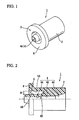
- Fig. 1 is a perspective view of a marker 1.
- the marker 1 is formed of an elastic material such as silicone rubber.
- the marker 1 includes a substantially cylindrical body 2 and a engaging portion 3 provided at a front end of the body 2.
- Fig. 2 is a right side view, partially shown in cross-section, of the marker 1.
- the marker 1 includes an insertion hole 4 along its central axis in which an endoscopic treatment tool is inserted.
- the insertion hole 4 includes a tip section 4A at the side of engaging portion 3, an inserting section 4C at the side of an opposite rear end, and a middle section 4B between the tip section 4A and the inserting section 4C.
- the tip section 4A is square-sectioned and functions as a fixing portion for fixing the body 2 to an intended position of the middle section of the endoscopic treatment tool due to frictional force generated at the contact face of the tip section 4A and the external surface of the endoscopic treatment tool as described later.
- the middle section 4B is circular-sectioned and has a diameter larger than the maximum inner diameter (i.e., the diagonal diameter in the cross-section) of the tip section 4A. Thus, the middle section 4B does not come in direct contact with an external surface of the endoscope treatment tool.
- the inserting section 4C is also circular-sectioned and has a diameter that is substantially the same as that of the middle section 4B at the side of the middle section 4B and gradually expands toward the rear end. Namely, the inserting section 4C is formed in a tapered shape such that the endoscopic treatment tool may be easily inserted from the expanded rear end of the insertion hole 4.
- the marker 1 is removably attached to the endoscopic treatment tool. In particular, after the endoscopic treatment tool is inserted from the inserting section 4C and the marker 1 is attached, the endoscopic treatment tool can be removed.
- the engaging portion 3 includes an annular engaging groove 5 provided in a circumferential direction thereof on a radial direction outside of the insertion hole 4, and a flange 6 circumferentially projecting from the radial direction outside of the engaging groove 5.
- the engaging groove 5 is provided between the external surface of the tip section 4A of the insertion hole 4 and the body 2 concentrically with the insertion hole 4. A guide sheath is engaged in the engaging groove 5 as described later.
- the engaging groove 5 includes a first surface 5A at the side of the flange 6 formed substantially parallel with the axial direction of the marker 1, and a second surface (wall surface) 5B at the side of the insertion hole 4 formed such that a radial direction width W1 of the engaging groove 5 at the front end is slightly larger than a radial direction width W2 at the rear end. That is, the engaging groove 5 is tapered such that the radial direction width thereof becomes smaller toward the axial direction of the insertion hole 4.
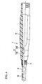
- Fig. 4 is a partial cross-sectional view of a guide sheath 7 used with the marker 1.
- the guide sheath 7 includes a tubular, flexible sheath body 8 made of, for example, resin, and a stick (engaging member) 9 attached to a base end of the sheath body 8.
- a tubular indexing member 10 made of stainless steel or the like is thermoformed at an inner surface of the sheath body 8 near the tip thereof. With the X-ray radioscopy, the indexing member 10 is an indication of the tip position of the sheath body 8. A base end of the sheath body 8 is press-fit at the tip of the stick 9 and is fixed by a coil 11 from the outside.
- the stick 9 is a tubular member made of resin or the like, and includes a through hole 12 inside thereof.
- An endoscopic treatment tool is inserted in the through hole 12.
- the through hole 12 is circular-sectioned and includes a first section 12A with a constant diameter and a second section 12B with a diameter gradually expanding toward the rear end.
- the inner surface of the second section 12B is formed such that the wall surface of the stick 9 becomes thicker in the axial direction of the stick 9 from the rear end where the stick 9 enters the engaging groove 5 of the marker 1.
- the taper angle of the inner surface of the second section 12B is larger than that of the second surface 5B of the engaging groove 5 of the marker 1.
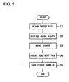
- FIG. 5 is a flow chart illustrating a procedure of lung biopsy using an endoscopic treatment tool performing with the marker 1 and the guide sheath 7.
- step S1 shown in Fig. 5 the guide sheath 7 is moved to the target site where tissue samples are to be taken.
- the endoscope is advanced within a bronchus while the position of the target site is observed through X-ray radioscopy images.
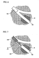
- Fig. 6 illustrates a state in which an endoscope 100 is advanced to the vicinity of a target site R. Since the diameter of a bronchiole 101 in which the target site R exists is smaller than that of the endoscope 100, the endoscope 100 cannot be advanced further toward the target site R.
- an ultrasonic probe 102 placed in the guide sheath 7 is inserted together with the guide sheath 7 from an opening for forceps (not shown) of the endoscope 100 and is projected from the tip of the endoscope 100 as shown in Fig. 7 . Since the diameters of the sheath body 8 and the ultrasonic probe 102 of the guide sheath 7 are smaller than that of the endoscope 100, the guide sheath 7 can reach the target site R through the bronchiole 101.
- the sheath body 8 itself is stopped at a position considered near but not touching the target site R, and the ultrasonic probe 102 is moved ahead to a position beyond the target site R. Then, the ultrasonic probe 102 is slowly pulled back in the direction of an arrow in Fig. 8 .
- Images of the tissue around the ultrasonic probe 102 are displayed on unillustrated test equipment through the ultrasonic wave emitted from the ultrasonic probe 102. Thus, the operator can confirm whether the ultrasonic probe 102 has reached the target site R.
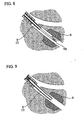
- step S2 the sheath body 8 is advanced to the vicinity of the target site R along the ultrasonic probe 102 as shown in Fig. 9 .
- the position of the tip of the sheath body 8 is confirmed by the indexing member 10 (not shown).
- the position of the ultrasonic probe 102 projected from the rear end of the stick 9 of the guide sheath 7 is marked. Then, only the ultrasonic probe 102 is removed from the guide sheath 7 and the guide sheath 7 is held there.
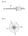
- a known biopsy cup (endoscopic treatment tool) 103 is inserted in the insertion hole 4 from the rear end of the marker 1, and the marker 1 is fixed to the biopsy cup 103 as shown in Fig. 10 .
- the marker 1 is then slid to a position where the distance between the rear end of the engaging groove 5 and the tip of the biopsy cup equals the distance between the tip of the ultrasonic probe 102 and the marking taken in step S2.
- biopsy cup 103 instead of the biopsy cup 103, other treatment tools such as a biopsy brush may alternatively be used.
- the tip section 4A of the insertion hole 4 which functions as the fixing portion is square-sectioned, the tip section 4A is made to contact the biopsy cup 103 at four sides 4D as shown in Fig. 11 .
- the frictional force generated between the tip section 4A and the biopsy cups 103 is small, whereby the marker 1 can be slid smoothly for positional alignment.
- the marker 1 is formed of a transparent material, the rear end of the engaging groove 5 is more clearly visible, and positioning of the marker 1 can be made more precisely.
- step S4 the biopsy cup 103 to which the marker 1 is attached is inserted in the guide sheath 7 from the base end of the stick 9. Then, as shown in the dotted line in Fig. 12 , the rear end of the stick 9 is made to advance into the engaging groove 5 of the marker 1, and the marker 1 is engaged in the guide sheath 7.
- the taper angle of the inner surface of the second section 12B of the through hole 12 formed in the stick 9 is larger than that of the second surface 5B of the engaging groove 5 of the marker 1, the second surface 5B of the engaging groove 5 is pressed against the insertion hole 4 as the stick 9 advances in the engaging groove 5.
- the tip section 4A of the insertion hole 4 nips the biopsy cup 103 with far stronger force than before engagement, while keeping point contact with the biopsy cup 103.
- the marker 1 is securely fixed to the biopsy cup 103, and forward and backward movement of the biopsy cup 103 within the guide sheath 7 is prevented.
- the biopsy cup 103 is projected only the same distance as that of the ultrasonic probe 102 in step S2 from the tip of the sheath body 8, and the tip of the biopsy cup 103 reliably reaches the target site R as shown in Fig. 14 .
- step S5 the biopsy cup 103 is operated to take tissue samples at the target site R. After taking the tissue samples, the biopsy cup 103 is removed and the tissue samples are collected. Taking tissue samples in step S5 may be repeated several times when needed. It is also possible to estimate the size (i.e., the length along the direction in which the bronchiole 101 extends) of the target site R by repeating taking tissue samples several times with the position of the marker 1 fine-controlled and moving the tip of the biopsy cut 103 forward and backward in order to specify the position at which no more tissue sample can be taken.
- the size i.e., the length along the direction in which the bronchiole 101 extends
- a projecting length of the biopsy cup 103 from the guide sheath 7 may be determined in advance, the marker 1 may be attached at a predetermined position on the biopsy cup 103 so that the biopsy cup 103 projects at the predetermined length, and then the guide sheath 7 may be disposed such that the distance between the tip of the ultrasonic probe 102 and the tip of the guide sheath 7 equals the above predetermined length while observing via X-ray radioscopy.
- step S1 instead of providing the ultrasonic probe 102, the biopsy cup 103 inserted in the guide sheath may be advanced to the target site R.
- the guide sheath 7 alone may be advanced to the target site.
- X-ray radioscopy, a ultrasonic image or an endoscope image may be suitably selected for guiding instruments to the target site R
- the marker 1 is attached to the biopsy cup 103 before the biopsy cup 103 is inserted in the guide sheath 7, but the marker 1 is not necessarily engaged and fixed to the stick 9 immediately after the ultrasonic probe 102 is removed.
- the marker 1 may be engaged with the stick 9 when the tip of the biopsy cup 103 is positioned under X-ray radioscopy, thereby positioning and engagement may occur at the same time.
- the positional relationship between the biopsy cup 103 and the guide sheath 7 is fixed when the engaging groove 5 of the engaging portion 3 engages the guide sheath 7.
- the tip of the biopsy cup 103 can be projected precisely by the predetermined amount.
- the tip of the biopsy cup 103 can reliably reach the target site R, thereby performing a precise biopsy.
- the marker 1 is slidably fixed to the biopsy cup 103 in the axial direction thereof due to frictional force between the inner surface of the tip section 4A of the insertion hole 4 and the outer surface of the biopsy cup 103.
- the projecting length of the biopsy cup 103 from the guide sheath 7 can be controlled as intended by changing the position at which the marker 1 is fixed to the biopsy cup 103.
- the marker 1 and the biopsy cup 103 are in contact with each other not in the entire inner surface of the insertion hole 4, but only in the inner surface of the tip section 4A. Further, since the tip section 4A is square-sectioned as described above, the tip section 4A is made to point contact with the biopsy cup 103 only at four sides 4D. Thus, since the marker 1 is structured to have a smaller contact area with the biopsy cup 103 to be attached to, the frictional force generated between the marker 1 and the biopsy cups 103 in the axial direction is small, whereby the marker 1 can be slid smoothly for positional alignment
- the marker 1 is engaged with the stick 9 of the guide sheath 7 such that, as the stick 9 advances in the engaging groove 5, the second surface 5B of the engaging groove 5 is pressed against the insertion hole 4 due to a difference in taper angles as described above.
- the marker 1 is firmly fixed to the biopsy cup 103, and the positional relationship with the guide sheath 7 in operation including taking tissue samples is reliably maintained. In this manner, a marker which slides smoothly for positional alignment and is firmly fixed for engagement can be obtained.
- the flange 6 is provided in the engaging portion 3, even if the external surface of the body 2 is drawn toward the rear end side due to deformation at the time of engagement with the stick 9, the flange 6 moves toward the radial direction inner side, the movement of the entire external surface of the body 2 can be prevented. Therefore, a marker with holding performance which is not easily decline during engagement can be obtained.
- the marker 1 includes the engaging portion 3 and is engaged with the base end of the guide sheath 7, an abutting portion may be provided instead of the engaging portion 3 for abutting the base end of the guide sheath 7.
- a front end surface of the body 2 abuts the base end of the guide sheath 7 and functions as the abutting portion. In this manner, when the endoscopic treatment tool with the marker attached thereon is inserted in the guide sheath and the abutting portion is made to abut the base end of the guide sheath, a predetermined length of the tip of the endoscopic treatment tool can always be projected from the tip of the guide sheath.
- the marker 1 is fixed slidably in the axial direction of the endoscopic treatment tool by the inner surface of the insertion hole 4, the invention is not limited thereto.
- the marker 1 may be removably fixed at an intended position by nipping the endoscopic treatment tool like a clip.
- neither the engaging portion nor the abutting portion is indispensable. So long as the marker is fixed to a predetermined position of the endoscopic treatment tool, when the guide sheath is inserted to the position of the marker, a predetermined length of the tip of the endoscopic treatment tool can always be projected from the tip of the guide sheath.
- the marker is attached to the endoscopic treatment tool such as the biopsy cup for taking tissue samples, the invention is not limited thereto.
- the marker may be attached to any treatment tools that are difficult to locate in a body.
- the marker of the invention may be attached to an ultrasonic probe for reliable ultrasonic image diagnosis in a position repeatedly.
Description
- The present invention relates to a marker and a guide sheath system to be attached to an endoscopic treatment tool.
- An operator performing an endoscopic biopsy of a peripheral lesion in a lung often locates a target site in a bronchiole. The bronchiole diameter is so small that a usual endoscope tip cannot reach the target site. In some cases, the bronchiole may be branched several times from the tip of the endoscope to the target site, and thus it is difficult to repeatedly make the treatment tool reach the target site after taking biopsy tissue samples at that site.
- To address this problem, Japanese Unexamined Patent Application, First Publication No.
2004-154485 - A targeted lesion is often very small. Even if a lesion is detected by using a ultrasonic probe or other instruments, it is difficult for an operator to determine how far the treatment tool such as forceps is to be advanced for performing biopsy after the removal of the ultrasonic probe. Merely several millimeters of misalignment may cause the treatment tool to miss the target site. A problem has currently arisen that it is only after the inspection is completed that the operator finds out whether or not proper tissue samples were taken. In addition, usually the tissue samples are taken five or six times at a site, the above-mentioned problem may occur more often. In fact, accuracy in such a biopsy is currently insufficient.
- If the tip position of the treatment tool is observed at all times by X-ray radioscopy, the above problems may be avoided. However, the X-ray radioscopy may expose the patient to radiation in a large amount. Thus, it is a seriously invasive procedure for just an inspection.
-
EP 0 834 278 discloses a treatment accessory for an endoscope. The treatment accessory comprises a shaft, an operation unit connected to a proximal end of the shaft, a treatment device provided at the distal end of the shaft, and a ring initially located at a predetermined length from the distal end of the treatment device. The length is greater than the length by which the treatment device extends from a forceps channel of the endoscope, when the treatment accessory is in normal use, so that the ring stays inside the forceps channel when the treatment device is operated. The length may be adjusted according to use. The ring is slidable on the shaft and may comprise a flange portion at the treatment side of the ring. The flange portion prevents that the ring enters the forceps channel even if the inlet of the forceps channel is not provided with a tap and is open. - In view of the above, an object of the invention is to provide a marker and a guide sheath system to be attached to an endoscopic treatment tool for precisely directing a tip of the treatment tool to a target site with no additional physical burden to the patient.
- As claimed, there is provided a marker adapted for use with an endoscopis treatment tool adapted to be inserted in a guide sheath. The marker comprises a body and a fixing portion for removably fixing the body to a middle section of the endoscopic treatment tool, wherein the distance between the body and a tip of the endoscopic treatment tool can be determined freely. The marker further comprises an engaging portion adapted to be engaged with a base end of the guide sheath. According to the Intention, the engaging portion of the marker of the endoscopic treatment tool includes a circumferential engaging groove formed in a radial direction outside of the insertion hole.
- As further claimed, there is provided a guide sheath system for an endoscopic treatment tool, the system comprising: a marker adapted for use with in an endoscopic treatment tool as described above; and a guide sheath which includes at a base end thereof a tubular engaging member which is adapted to be engaged with the engaging groove of the engaging portion of the marker.
- With the marker used in the endoscopic treatment tool of the invention, an operator can control the endoscopic treatment tool such that a desired length of the marker inserted in the guide sheath is projected from the guide sheath tip by fixing the marker on the fixing portion at a desired position of the middle section of the endoscopic treatment tool. In addition, the marker used in the endoscopic treatment tool can be securely fixed to the guide sheath.
- The body may be formed of an elastic material and may include an insertion hole in which the endoscopic, treatment tool is inserted; and the fixing portion may be defined by an inner wall of the insertion hole and fixes the body to be slidable in an axial direction of the endoscopic treatment tool due to frictional force generated between the endoscopic treatment tool and the inner wall of the insertion hole.
- The marker used in the endoscopic treatment tool of the invention may further include an abutting portion which abuts a base end of the guide sheath, wherein the abutting portion may be made to abut the base end of the guide sheath to allow the tip of the endoscopic treatment tool to project from the tip of the guide sheath by a predetermined amount.
- The marker used in the endoscopic treatment tool of the invention further includes an engaging portion to be engaged with the base end of the guide sheath, wherein the engaging portion may be made to be engaged with the base end of the guide sheath to allow the tip of the endoscopic treatment tool to project from the tip of the guide sheath by a predetermined amount.
- According to the guide sheath system of the invention, the tip of the endoscopic treatment tool can be projected precisely with the marker used in the endoscopic treatment tool engaged into the engaging member provided at the base end of the guide sheath.
- A wall surface of the engaging groove at the side of the insertion hole may be formed such that the engaging groove has a radial direction width which becomes gradually smaller along an axial direction of the insertion hole from an end at which the engaging member enters; an inner surface of the engaging member may be formed such that a wall thickness of the engaging member becomes thicker in an axial direction of the engaging member from an end at which the engaging member enters the engaging groove; a taper angle of the inner surface of the engaging member may be larger than that of the wall surface at the side of the insertion hole of the engaging groove; when the engaging member advances in the engaging groove, the wall surface at the side of the insertion hole of the engaging groove may be pressed against the insertion hole and the body may be fixed to the endoscopic treatment tool.
- With this structure, the guide sheath system can be obtained that firmly fixes the endoscopic treatment tool while sliding resistance during adjustment of the fixing position is small.
- According to the marker and the guide sheath system used in the endoscopic treatment tool of the invention, the tip of the endoscopic treatment tool can be precisely positioned at the target site with no additional physical burden to the patient.
-
-
Fig. 1 is a perspective view of a marker used in an endoscopic treatment tool according to an embodiment of the invention. -
Fig. 2 is a right side view, partially shown in cross-section, of the marker used in the endoscopic treatment tool. -
Fig. 3 is a front view of the marker used in the endoscopic treatment tool. -
Fig. 4 is a partial cross-sectional view of a guide sheath used with the endoscopic treatment tool. -
Fig. 5 is a flow chart illustrating the procedure of lung biopsy using the marker used in the endoscopic treatment tool. -
Fig. 6 is a view illustrating a state in which the endoscope is moved near the target site. -
Fig. 7 is a view illustrating a state in which an ultrasonic probe is projected from the endoscope. -
Fig. 8 is a view illustrating a state in which an image of the target site is obtained with the ultrasonic probe. -
Fig. 9 is a view illustrating a state in which the guide sheath is held at the target site. -
Fig. 10 is a view illustrating a state in which the marker used in the endoscopic treatment tool is attached to a biopsy cup. -
Fig. 11 is a front view of the marker used in the endoscopic treatment tool with the biopsy cup attached thereto. -
Fig. 12 is a view illustrating a state in which the marker used in the endoscopic treatment tool with the biopsy cup attached thereto is inserted in the guide sheath. -
Fig. 13 is a front view illustrating a state in which the marker used in the endoscopic treatment tool with the biopsy cup attached thereto is inserted in the guide sheath. -
Fig. 14 is a view illustrating a state in which tissue of the target site is taken using the biopsy cup. - Referring now to
Figs. 1 to 13 , a marker used in the endoscopic treatment tool (hereinafter, referred to as "marker") according to an embodiment of the invention will be described. -
Fig. 1 is a perspective view of amarker 1. Themarker 1 is formed of an elastic material such as silicone rubber. Themarker 1 includes a substantiallycylindrical body 2 and a engaging portion 3 provided at a front end of thebody 2. -
Fig. 2 is a right side view, partially shown in cross-section, of themarker 1. Themarker 1 includes aninsertion hole 4 along its central axis in which an endoscopic treatment tool is inserted. Theinsertion hole 4 includes atip section 4A at the side of engaging portion 3, aninserting section 4C at the side of an opposite rear end, and amiddle section 4B between thetip section 4A and theinserting section 4C. - As shown in
Figs. 1 and3 , thetip section 4A is square-sectioned and functions as a fixing portion for fixing thebody 2 to an intended position of the middle section of the endoscopic treatment tool due to frictional force generated at the contact face of thetip section 4A and the external surface of the endoscopic treatment tool as described later. - The
middle section 4B is circular-sectioned and has a diameter larger than the maximum inner diameter (i.e., the diagonal diameter in the cross-section) of thetip section 4A. Thus, themiddle section 4B does not come in direct contact with an external surface of the endoscope treatment tool. - The
inserting section 4C is also circular-sectioned and has a diameter that is substantially the same as that of themiddle section 4B at the side of themiddle section 4B and gradually expands toward the rear end. Namely, the insertingsection 4C is formed in a tapered shape such that the endoscopic treatment tool may be easily inserted from the expanded rear end of theinsertion hole 4. Themarker 1 is removably attached to the endoscopic treatment tool. In particular, after the endoscopic treatment tool is inserted from the insertingsection 4C and themarker 1 is attached, the endoscopic treatment tool can be removed. - The engaging portion 3 includes an annular
engaging groove 5 provided in a circumferential direction thereof on a radial direction outside of theinsertion hole 4, and aflange 6 circumferentially projecting from the radial direction outside of the engaginggroove 5. - The engaging
groove 5 is provided between the external surface of thetip section 4A of theinsertion hole 4 and thebody 2 concentrically with theinsertion hole 4. A guide sheath is engaged in the engaginggroove 5 as described later. - As shown in
Fig. 2 , the engaginggroove 5 includes afirst surface 5A at the side of theflange 6 formed substantially parallel with the axial direction of themarker 1, and a second surface (wall surface) 5B at the side of theinsertion hole 4 formed such that a radial direction width W1 of the engaginggroove 5 at the front end is slightly larger than a radial direction width W2 at the rear end. That is, the engaginggroove 5 is tapered such that the radial direction width thereof becomes smaller toward the axial direction of theinsertion hole 4. -
Fig. 4 is a partial cross-sectional view of aguide sheath 7 used with themarker 1. Theguide sheath 7 includes a tubular,flexible sheath body 8 made of, for example, resin, and a stick (engaging member) 9 attached to a base end of thesheath body 8. - As shown in
Fig. 4 , atubular indexing member 10 made of stainless steel or the like is thermoformed at an inner surface of thesheath body 8 near the tip thereof. With the X-ray radioscopy, the indexingmember 10 is an indication of the tip position of thesheath body 8. A base end of thesheath body 8 is press-fit at the tip of thestick 9 and is fixed by acoil 11 from the outside. - The
stick 9 is a tubular member made of resin or the like, and includes a throughhole 12 inside thereof. An endoscopic treatment tool is inserted in the throughhole 12. The throughhole 12 is circular-sectioned and includes afirst section 12A with a constant diameter and a second section 12B with a diameter gradually expanding toward the rear end. The inner surface of the second section 12B is formed such that the wall surface of thestick 9 becomes thicker in the axial direction of thestick 9 from the rear end where thestick 9 enters the engaginggroove 5 of themarker 1. The taper angle of the inner surface of the second section 12B is larger than that of thesecond surface 5B of the engaginggroove 5 of themarker 1. - Referring now to
Figs. 5 to 13 , an operation of themarker 1 and theguide sheath 7 will be described.Fig. 5 is a flow chart illustrating a procedure of lung biopsy using an endoscopic treatment tool performing with themarker 1 and theguide sheath 7. - First, in step S1 shown in
Fig. 5 , theguide sheath 7 is moved to the target site where tissue samples are to be taken. In particular, the endoscope is advanced within a bronchus while the position of the target site is observed through X-ray radioscopy images. -
Fig. 6 illustrates a state in which anendoscope 100 is advanced to the vicinity of a target site R. Since the diameter of abronchiole 101 in which the target site R exists is smaller than that of theendoscope 100, theendoscope 100 cannot be advanced further toward the target site R. - Here, an
ultrasonic probe 102 placed in theguide sheath 7 is inserted together with theguide sheath 7 from an opening for forceps (not shown) of theendoscope 100 and is projected from the tip of theendoscope 100 as shown inFig. 7 . Since the diameters of thesheath body 8 and theultrasonic probe 102 of theguide sheath 7 are smaller than that of theendoscope 100, theguide sheath 7 can reach the target site R through thebronchiole 101. - As shown in
Fig. 8 , thesheath body 8 itself is stopped at a position considered near but not touching the target site R, and theultrasonic probe 102 is moved ahead to a position beyond the target site R. Then, theultrasonic probe 102 is slowly pulled back in the direction of an arrow inFig. 8 . - Images of the tissue around the
ultrasonic probe 102 are displayed on unillustrated test equipment through the ultrasonic wave emitted from theultrasonic probe 102. Thus, the operator can confirm whether theultrasonic probe 102 has reached the target site R. - After the operator confirmed that the
ultrasonic probe 102 has reached the target site R, the procedure proceeds to step S2. In step S2, thesheath body 8 is advanced to the vicinity of the target site R along theultrasonic probe 102 as shown inFig. 9 . The position of the tip of thesheath body 8 is confirmed by the indexing member 10 (not shown). - Here, in a state in which the tip of the
ultrasonic probe 102 is placed in the position where the tissue samples are to be taken, the position of theultrasonic probe 102 projected from the rear end of thestick 9 of theguide sheath 7 is marked. Then, only theultrasonic probe 102 is removed from theguide sheath 7 and theguide sheath 7 is held there. - In the next step S3, a known biopsy cup (endoscopic treatment tool) 103 is inserted in the
insertion hole 4 from the rear end of themarker 1, and themarker 1 is fixed to thebiopsy cup 103 as shown inFig. 10 . Themarker 1 is then slid to a position where the distance between the rear end of the engaginggroove 5 and the tip of the biopsy cup equals the distance between the tip of theultrasonic probe 102 and the marking taken in step S2. - Instead of the
biopsy cup 103, other treatment tools such as a biopsy brush may alternatively be used. - As described above, since the
tip section 4A of theinsertion hole 4 which functions as the fixing portion is square-sectioned, thetip section 4A is made to contact thebiopsy cup 103 at foursides 4D as shown inFig. 11 . Thus, the frictional force generated between thetip section 4A and the biopsy cups 103 is small, whereby themarker 1 can be slid smoothly for positional alignment. - If the
marker 1 is formed of a transparent material, the rear end of the engaginggroove 5 is more clearly visible, and positioning of themarker 1 can be made more precisely. - Next, in step S4, the
biopsy cup 103 to which themarker 1 is attached is inserted in theguide sheath 7 from the base end of thestick 9. Then, as shown in the dotted line inFig. 12 , the rear end of thestick 9 is made to advance into the engaginggroove 5 of themarker 1, and themarker 1 is engaged in theguide sheath 7. - Since the taper angle of the inner surface of the second section 12B of the through
hole 12 formed in thestick 9 is larger than that of thesecond surface 5B of the engaginggroove 5 of themarker 1, thesecond surface 5B of the engaginggroove 5 is pressed against theinsertion hole 4 as thestick 9 advances in the engaginggroove 5. As a result, as shown inFig. 13 , thetip section 4A of theinsertion hole 4 nips thebiopsy cup 103 with far stronger force than before engagement, while keeping point contact with thebiopsy cup 103. As a result, themarker 1 is securely fixed to thebiopsy cup 103, and forward and backward movement of thebiopsy cup 103 within theguide sheath 7 is prevented. - In the state in which the
marker 1 and thestick 9 are engaged together, thebiopsy cup 103 is projected only the same distance as that of theultrasonic probe 102 in step S2 from the tip of thesheath body 8, and the tip of thebiopsy cup 103 reliably reaches the target site R as shown inFig. 14 . - Here, in step S5, the
biopsy cup 103 is operated to take tissue samples at the target site R. After taking the tissue samples, thebiopsy cup 103 is removed and the tissue samples are collected. Taking tissue samples in step S5 may be repeated several times when needed. It is also possible to estimate the size (i.e., the length along the direction in which thebronchiole 101 extends) of the target site R by repeating taking tissue samples several times with the position of themarker 1 fine-controlled and moving the tip of the biopsy cut 103 forward and backward in order to specify the position at which no more tissue sample can be taken. - The steps shown in
Fig. 5 are not necessarily performed in the described order. Instead, a projecting length of thebiopsy cup 103 from theguide sheath 7 may be determined in advance, themarker 1 may be attached at a predetermined position on thebiopsy cup 103 so that thebiopsy cup 103 projects at the predetermined length, and then theguide sheath 7 may be disposed such that the distance between the tip of theultrasonic probe 102 and the tip of theguide sheath 7 equals the above predetermined length while observing via X-ray radioscopy. - In step S1, instead of providing the
ultrasonic probe 102, thebiopsy cup 103 inserted in the guide sheath may be advanced to the target site R. Alternatively, theguide sheath 7 alone may be advanced to the target site. X-ray radioscopy, a ultrasonic image or an endoscope image may be suitably selected for guiding instruments to the target site R - The
marker 1 is attached to thebiopsy cup 103 before thebiopsy cup 103 is inserted in theguide sheath 7, but themarker 1 is not necessarily engaged and fixed to thestick 9 immediately after theultrasonic probe 102 is removed. For example, themarker 1 may be engaged with thestick 9 when the tip of thebiopsy cup 103 is positioned under X-ray radioscopy, thereby positioning and engagement may occur at the same time. - According to the
marker 1 of the present embodiment, the positional relationship between thebiopsy cup 103 and theguide sheath 7 is fixed when the engaginggroove 5 of the engaging portion 3 engages theguide sheath 7. In this manner, the tip of thebiopsy cup 103 can be projected precisely by the predetermined amount. Thus, the tip of thebiopsy cup 103 can reliably reach the target site R, thereby performing a precise biopsy. - The
marker 1 is slidably fixed to thebiopsy cup 103 in the axial direction thereof due to frictional force between the inner surface of thetip section 4A of theinsertion hole 4 and the outer surface of thebiopsy cup 103. Thus, the projecting length of thebiopsy cup 103 from theguide sheath 7 can be controlled as intended by changing the position at which themarker 1 is fixed to thebiopsy cup 103. - The
marker 1 and thebiopsy cup 103 are in contact with each other not in the entire inner surface of theinsertion hole 4, but only in the inner surface of thetip section 4A. Further, since thetip section 4A is square-sectioned as described above, thetip section 4A is made to point contact with thebiopsy cup 103 only at foursides 4D. Thus, since themarker 1 is structured to have a smaller contact area with thebiopsy cup 103 to be attached to, the frictional force generated between themarker 1 and the biopsy cups 103 in the axial direction is small, whereby themarker 1 can be slid smoothly for positional alignment - The
marker 1 is engaged with thestick 9 of theguide sheath 7 such that, as thestick 9 advances in the engaginggroove 5, thesecond surface 5B of the engaginggroove 5 is pressed against theinsertion hole 4 due to a difference in taper angles as described above. Thus, themarker 1 is firmly fixed to thebiopsy cup 103, and the positional relationship with theguide sheath 7 in operation including taking tissue samples is reliably maintained. In this manner, a marker which slides smoothly for positional alignment and is firmly fixed for engagement can be obtained. - In addition, since the
flange 6 is provided in the engaging portion 3, even if the external surface of thebody 2 is drawn toward the rear end side due to deformation at the time of engagement with thestick 9, theflange 6 moves toward the radial direction inner side, the movement of the entire external surface of thebody 2 can be prevented. Therefore, a marker with holding performance which is not easily decline during engagement can be obtained. - While the embodiments of the invention have been described, the technical range of the invention is not limited to those described. Various modifications may be made without departing from the scope of the invention.
- In the described embodiment, although the
marker 1 includes the engaging portion 3 and is engaged with the base end of theguide sheath 7, an abutting portion may be provided instead of the engaging portion 3 for abutting the base end of theguide sheath 7. - In particular, if the engaging
groove 5 is not provided in themarker 1, a front end surface of thebody 2 abuts the base end of theguide sheath 7 and functions as the abutting portion. In this manner, when the endoscopic treatment tool with the marker attached thereon is inserted in the guide sheath and the abutting portion is made to abut the base end of the guide sheath, a predetermined length of the tip of the endoscopic treatment tool can always be projected from the tip of the guide sheath. - In the described embodiment, although the
marker 1 is fixed slidably in the axial direction of the endoscopic treatment tool by the inner surface of theinsertion hole 4, the invention is not limited thereto. For example, themarker 1 may be removably fixed at an intended position by nipping the endoscopic treatment tool like a clip. - In addition, neither the engaging portion nor the abutting portion is indispensable. So long as the marker is fixed to a predetermined position of the endoscopic treatment tool, when the guide sheath is inserted to the position of the marker, a predetermined length of the tip of the endoscopic treatment tool can always be projected from the tip of the guide sheath.
- In addition, in the described embodiment, although the marker is attached to the endoscopic treatment tool such as the biopsy cup for taking tissue samples, the invention is not limited thereto. The marker may be attached to any treatment tools that are difficult to locate in a body.
- For example, the marker of the invention may be attached to an ultrasonic probe for reliable ultrasonic image diagnosis in a position repeatedly.
Claims (7)
- A marker (1) adapted for use with an endoscopic treatment tool (103) adapted to be inserted in a guide sheath (7), wherein the marker (1) comprises:a body (2) which includes an insertion hole (4) in which the endoscopic treatment tool is inserted; anda fixing portion (4A) for removably fixing the body (2) to a middle section of the endoscopic treatment tool,wherein the distance between the body (2) and a tip of the endoscopic treatment tool can be determined freely,wherein the marker (1) further comprises an engaging portion (3) adapted to be engaged with a base end of the guide sheath (7),characterized in that the engaging portion (3) of the marker (1) of the endoscopic treatment tool includes a circumferential engaging groove (5) formed in a radial direction outside of the insertion hole (4).
- The marker (1) according to claim 1, wherein the guide sheath (7) includes at a base end thereof a tubular engaging member (9) which is adapted to be engaged with the engaging groove (5) of the engaging portion (3) of the marker (1), and wherein when the engaging member (9) advances in the engaging groove (5), the guide sheath (7) and the marker (1) used in the endoscopic treatment tool engage each other.
- The marker according to claim 1 or 2, wherein: the body (2) is formed of an elastic material and includes the insertion hole (4), and the fixing portion (4A) is defined by an inner wall of the insertion hole (4) and fixes the body (2) to be slidable in an axial direction of the endoscopic treatment tool due to frictional force generated between the endoscopic treatment tool and the inner wall of the insertion hole (4).
- The marker according to any one of the claims 1 to 3, further comprising an abutting portion which abuts the base end of the guide sheath (7), wherein the abutting portion is made to abut the base end of the guide sheath (7) to allow the tip of the endoscopic treatment tool to project from the tip of the guide sheath (7) by a predetermined amount.
- The marker according to claim 3, wherein the engaging portion (3) is made to be engaged with the base end of the guide sheath (7) to allow the tip of the endoscopic treatment tool to project from the tip of the guide sheath (7) by a predetermined amount.
- A guide sheath system for an endoscopic treatment tool, wherein the guide sheath system comprises:a marker (1) adapted for use with in an endoscopic treatment tool according to any one of the claims 1 to 5 ; anda guide sheath (7) which includes at a base end thereof a tubular engaging member (9) which is adapted to be engaged with the engaging groove (5) of the engaging portion (3) of the marker (1).
- The guide sheath system according to claim 6, wherein a wall surface of the engaging groove (5) at the side of the insertion hole (4) is formed such that the engaging groove (5) has a radial direction width which becomes gradually smaller along an axial direction of the insertion hole (4) from an end at which the engaging member (9) enters; an inner surface of the engaging member (9) is formed such that a wall thickness of the engaging member (9) becomes thicker in an axial direction of the engaging member (9) from an end at which the engaging member (9) enters the engaging groove (5); a taper angle of the inner surface of the engaging member (9) is larger than that of the wall surface at the side of the insertion hole (4) of the engaging groove (5); when the engaging member (9) advances in the engaging groove (5), the wall surface at the side of the insertion hole (4) of the engaging groove (5) is pressed against the insertion hole (4) and the body (2) is fixed to the endoscopic treatment tool.
Applications Claiming Priority (1)
| Application Number | Priority Date | Filing Date | Title |
|---|---|---|---|
| JP2007171851A JP5019975B2 (en) | 2007-06-29 | 2007-06-29 | Guide sheath system for endoscopic treatment tool |
Publications (2)
| Publication Number | Publication Date |
|---|---|
| EP2008592A1 EP2008592A1 (en) | 2008-12-31 |
| EP2008592B1 true EP2008592B1 (en) | 2012-04-18 |
Family
ID=39866613
Family Applications (1)
| Application Number | Title | Priority Date | Filing Date |
|---|---|---|---|
| EP08011542A Active EP2008592B1 (en) | 2007-06-29 | 2008-06-25 | Marker and guide sheath system for endoscopic treatment tool |
Country Status (3)
| Country | Link |
|---|---|
| US (1) | US8663095B2 (en) |
| EP (1) | EP2008592B1 (en) |
| JP (1) | JP5019975B2 (en) |
Families Citing this family (1)
| Publication number | Priority date | Publication date | Assignee | Title |
|---|---|---|---|---|
| USD879288S1 (en) | 2018-03-12 | 2020-03-24 | Olympus Corporation | Stopper for a medical guide sheath |
Family Cites Families (13)
| Publication number | Priority date | Publication date | Assignee | Title |
|---|---|---|---|---|
| US3977708A (en) * | 1975-09-11 | 1976-08-31 | Fluoroware, Inc. | Plastic tube fitting and joint |
| US4576162A (en) * | 1983-03-30 | 1986-03-18 | Mccorkle Charles E | Apparatus and method for separation of scar tissue in venous pathway |
| JPH0454970A (en) * | 1990-06-25 | 1992-02-21 | Olympus Optical Co Ltd | Medical treatment device |
| US5882293A (en) | 1996-09-05 | 1999-03-16 | Asahi Kogaku Kogyo Kabushiki Kaisha | Treatment accessories for endoscope |
| JP4129312B2 (en) * | 1998-03-13 | 2008-08-06 | オリンパス株式会社 | Endoscope device |
| JP3370601B2 (en) | 1998-05-28 | 2003-01-27 | ペンタックス株式会社 | Operation unit of endoscope treatment tool |
| US6210397B1 (en) * | 1999-01-13 | 2001-04-03 | A-Med Systems, Inc. | Sealing cannula device |
| JP4674990B2 (en) * | 2000-04-17 | 2011-04-20 | オリンパス株式会社 | Endoscope hood |
| US6544231B1 (en) * | 2000-05-22 | 2003-04-08 | Medcanica, Inc. | Catch, stop and marker assembly for a medical instrument and medical instrument incorporating the same |
| ITSV20010008A1 (en) * | 2001-03-05 | 2002-09-05 | Esaote Spa | NEEDLE GUIDE DEVICE IN PARTICULAR FOR ECHOGRAPHIC PROBES AND COMBINATION OF ECHOGRAPHIC PROBE AND SAID NEEDLE GUIDE DEVICE |
| JP3960904B2 (en) | 2002-11-08 | 2007-08-15 | オリンパスメディカルシステムズ株式会社 | Transendoscopic medical device |
| JP2006198299A (en) * | 2005-01-24 | 2006-08-03 | Pentax Corp | Tracheal endoscopic system |
| EP1949844A4 (en) * | 2005-11-14 | 2011-10-05 | Olympus Medical Systems Corp | Method of endoscopical diagnosis or treatment and medical device |
-
2007
- 2007-06-29 JP JP2007171851A patent/JP5019975B2/en active Active
-
2008
- 2008-06-25 EP EP08011542A patent/EP2008592B1/en active Active
- 2008-06-25 US US12/146,216 patent/US8663095B2/en active Active
Also Published As
| Publication number | Publication date |
|---|---|
| EP2008592A1 (en) | 2008-12-31 |
| JP2009006034A (en) | 2009-01-15 |
| JP5019975B2 (en) | 2012-09-05 |
| US8663095B2 (en) | 2014-03-04 |
| US20090005644A1 (en) | 2009-01-01 |
Similar Documents
| Publication | Publication Date | Title |
|---|---|---|
| JP5629043B1 (en) | Biopsy system | |
| JP3614943B2 (en) | Endoscopic puncture needle | |
| JP5249472B2 (en) | Biopsy treatment tool | |
| US9820724B2 (en) | Endoscope puncture needle and biopsy system | |
| WO2015190188A1 (en) | Biopsy system | |
| EP3081168B1 (en) | Puncture needle for ultrasonic endoscope | |
| JP5985129B1 (en) | Endoscopic puncture needle | |
| EP3178405A1 (en) | Puncture needle for endoscopes | |
| WO2015087939A1 (en) | Endoscope treatment instrument | |
| JP5327986B2 (en) | Endoscope insertion aid | |
| WO2016047202A1 (en) | Endoscope puncture needle | |
| US11696672B2 (en) | Endoscopic puncture needle | |
| WO2016042849A1 (en) | Biopsy system | |
| EP2008592B1 (en) | Marker and guide sheath system for endoscopic treatment tool | |
| US20170086802A1 (en) | Biopsy system and treatment tool | |
| WO2014045677A1 (en) | Biopsy needle and biopsy system | |
| JP5893814B1 (en) | Tissue collection system | |
| JP2007181539A (en) | Puncture needle for endoscope | |
| JP6535132B2 (en) | Treatment tool for endoscope | |
| JP2005329078A (en) | Puncture needle device for endoscope | |
| JP2009268499A (en) | Hood for endoscope |
Legal Events
| Date | Code | Title | Description |
|---|---|---|---|
| PUAI | Public reference made under article 153(3) epc to a published international application that has entered the european phase |
Free format text: ORIGINAL CODE: 0009012 |
|
| AK | Designated contracting states |
Kind code of ref document: A1 Designated state(s): AT BE BG CH CY CZ DE DK EE ES FI FR GB GR HR HU IE IS IT LI LT LU LV MC MT NL NO PL PT RO SE SI SK TR |
|
| AX | Request for extension of the european patent |
Extension state: AL BA MK RS |
|
| 17P | Request for examination filed |
Effective date: 20090305 |
|
| 17Q | First examination report despatched |
Effective date: 20090402 |
|
| AKX | Designation fees paid |
Designated state(s): DE FR GB IE |
|
| GRAP | Despatch of communication of intention to grant a patent |
Free format text: ORIGINAL CODE: EPIDOSNIGR1 |
|
| GRAS | Grant fee paid |
Free format text: ORIGINAL CODE: EPIDOSNIGR3 |
|
| GRAA | (expected) grant |
Free format text: ORIGINAL CODE: 0009210 |
|
| AK | Designated contracting states |
Kind code of ref document: B1 Designated state(s): DE FR GB IE |
|
| REG | Reference to a national code |
Ref country code: GB Ref legal event code: FG4D |
|
| REG | Reference to a national code |
Ref country code: IE Ref legal event code: FG4D |
|
| REG | Reference to a national code |
Ref country code: DE Ref legal event code: R096 Ref document number: 602008014847 Country of ref document: DE Effective date: 20120614 |
|
| PLBE | No opposition filed within time limit |
Free format text: ORIGINAL CODE: 0009261 |
|
| STAA | Information on the status of an ep patent application or granted ep patent |
Free format text: STATUS: NO OPPOSITION FILED WITHIN TIME LIMIT |
|
| 26N | No opposition filed |
Effective date: 20130121 |
|
| REG | Reference to a national code |
Ref country code: DE Ref legal event code: R097 Ref document number: 602008014847 Country of ref document: DE Effective date: 20130121 |
|
| PGFP | Annual fee paid to national office [announced via postgrant information from national office to epo] |
Ref country code: IE Payment date: 20140610 Year of fee payment: 7 Ref country code: GB Payment date: 20140625 Year of fee payment: 7 |
|
| PGFP | Annual fee paid to national office [announced via postgrant information from national office to epo] |
Ref country code: FR Payment date: 20140609 Year of fee payment: 7 |
|
| REG | Reference to a national code |
Ref country code: DE Ref legal event code: R082 Ref document number: 602008014847 Country of ref document: DE Representative=s name: WUESTHOFF & WUESTHOFF, PATENTANWAELTE PARTG MB, DE Ref country code: DE Ref legal event code: R081 Ref document number: 602008014847 Country of ref document: DE Owner name: OLYMPUS CORPORATION, JP Free format text: FORMER OWNER: OLYMPUS MEDICAL SYSTEMS CORP., TOKIO/TOKYO, JP |
|
| GBPC | Gb: european patent ceased through non-payment of renewal fee |
Effective date: 20150625 |
|
| REG | Reference to a national code |
Ref country code: IE Ref legal event code: MM4A |
|
| REG | Reference to a national code |
Ref country code: FR Ref legal event code: ST Effective date: 20160229 |
|
| PG25 | Lapsed in a contracting state [announced via postgrant information from national office to epo] |
Ref country code: IE Free format text: LAPSE BECAUSE OF NON-PAYMENT OF DUE FEES Effective date: 20150625 Ref country code: GB Free format text: LAPSE BECAUSE OF NON-PAYMENT OF DUE FEES Effective date: 20150625 |
|
| PG25 | Lapsed in a contracting state [announced via postgrant information from national office to epo] |
Ref country code: FR Free format text: LAPSE BECAUSE OF NON-PAYMENT OF DUE FEES Effective date: 20150630 |
|
| P01 | Opt-out of the competence of the unified patent court (upc) registered |
Effective date: 20230528 |
|
| PGFP | Annual fee paid to national office [announced via postgrant information from national office to epo] |
Ref country code: DE Payment date: 20230620 Year of fee payment: 16 |