EP2008513A1 - Water inlet arrangement - Google Patents
Water inlet arrangement Download PDFInfo
- Publication number
- EP2008513A1 EP2008513A1 EP20070012719 EP07012719A EP2008513A1 EP 2008513 A1 EP2008513 A1 EP 2008513A1 EP 20070012719 EP20070012719 EP 20070012719 EP 07012719 A EP07012719 A EP 07012719A EP 2008513 A1 EP2008513 A1 EP 2008513A1
- Authority
- EP
- European Patent Office
- Prior art keywords
- water
- tank
- inlet arrangement
- openings
- pipe
- Prior art date
- Legal status (The legal status is an assumption and is not a legal conclusion. Google has not performed a legal analysis and makes no representation as to the accuracy of the status listed.)
- Granted
Links
Images


Classifications
-
- A—HUMAN NECESSITIES
- A01—AGRICULTURE; FORESTRY; ANIMAL HUSBANDRY; HUNTING; TRAPPING; FISHING
- A01K—ANIMAL HUSBANDRY; CARE OF BIRDS, FISHES, INSECTS; FISHING; REARING OR BREEDING ANIMALS, NOT OTHERWISE PROVIDED FOR; NEW BREEDS OF ANIMALS
- A01K61/00—Culture of aquatic animals
- A01K61/10—Culture of aquatic animals of fish
-
- A—HUMAN NECESSITIES
- A01—AGRICULTURE; FORESTRY; ANIMAL HUSBANDRY; HUNTING; TRAPPING; FISHING
- A01K—ANIMAL HUSBANDRY; CARE OF BIRDS, FISHES, INSECTS; FISHING; REARING OR BREEDING ANIMALS, NOT OTHERWISE PROVIDED FOR; NEW BREEDS OF ANIMALS
- A01K63/00—Receptacles for live fish, e.g. aquaria; Terraria
- A01K63/003—Aquaria; Terraria
- A01K63/006—Accessories for aquaria or terraria
-
- A—HUMAN NECESSITIES
- A01—AGRICULTURE; FORESTRY; ANIMAL HUSBANDRY; HUNTING; TRAPPING; FISHING
- A01K—ANIMAL HUSBANDRY; CARE OF BIRDS, FISHES, INSECTS; FISHING; REARING OR BREEDING ANIMALS, NOT OTHERWISE PROVIDED FOR; NEW BREEDS OF ANIMALS
- A01K61/00—Culture of aquatic animals
-
- A—HUMAN NECESSITIES
- A01—AGRICULTURE; FORESTRY; ANIMAL HUSBANDRY; HUNTING; TRAPPING; FISHING
- A01K—ANIMAL HUSBANDRY; CARE OF BIRDS, FISHES, INSECTS; FISHING; REARING OR BREEDING ANIMALS, NOT OTHERWISE PROVIDED FOR; NEW BREEDS OF ANIMALS
- A01K63/00—Receptacles for live fish, e.g. aquaria; Terraria
- A01K63/04—Arrangements for treating water specially adapted to receptacles for live fish
- A01K63/042—Introducing gases into the water, e.g. aerators, air pumps
-
- Y—GENERAL TAGGING OF NEW TECHNOLOGICAL DEVELOPMENTS; GENERAL TAGGING OF CROSS-SECTIONAL TECHNOLOGIES SPANNING OVER SEVERAL SECTIONS OF THE IPC; TECHNICAL SUBJECTS COVERED BY FORMER USPC CROSS-REFERENCE ART COLLECTIONS [XRACs] AND DIGESTS
- Y02—TECHNOLOGIES OR APPLICATIONS FOR MITIGATION OR ADAPTATION AGAINST CLIMATE CHANGE
- Y02A—TECHNOLOGIES FOR ADAPTATION TO CLIMATE CHANGE
- Y02A40/00—Adaptation technologies in agriculture, forestry, livestock or agroalimentary production
- Y02A40/80—Adaptation technologies in agriculture, forestry, livestock or agroalimentary production in fisheries management
- Y02A40/81—Aquaculture, e.g. of fish
-
- Y—GENERAL TAGGING OF NEW TECHNOLOGICAL DEVELOPMENTS; GENERAL TAGGING OF CROSS-SECTIONAL TECHNOLOGIES SPANNING OVER SEVERAL SECTIONS OF THE IPC; TECHNICAL SUBJECTS COVERED BY FORMER USPC CROSS-REFERENCE ART COLLECTIONS [XRACs] AND DIGESTS
- Y10—TECHNICAL SUBJECTS COVERED BY FORMER USPC
- Y10T—TECHNICAL SUBJECTS COVERED BY FORMER US CLASSIFICATION
- Y10T137/00—Fluid handling
- Y10T137/0318—Processes
-
- Y—GENERAL TAGGING OF NEW TECHNOLOGICAL DEVELOPMENTS; GENERAL TAGGING OF CROSS-SECTIONAL TECHNOLOGIES SPANNING OVER SEVERAL SECTIONS OF THE IPC; TECHNICAL SUBJECTS COVERED BY FORMER USPC CROSS-REFERENCE ART COLLECTIONS [XRACs] AND DIGESTS
- Y10—TECHNICAL SUBJECTS COVERED BY FORMER USPC
- Y10T—TECHNICAL SUBJECTS COVERED BY FORMER US CLASSIFICATION
- Y10T137/00—Fluid handling
- Y10T137/8593—Systems
- Y10T137/85938—Non-valved flow dividers
-
- Y—GENERAL TAGGING OF NEW TECHNOLOGICAL DEVELOPMENTS; GENERAL TAGGING OF CROSS-SECTIONAL TECHNOLOGIES SPANNING OVER SEVERAL SECTIONS OF THE IPC; TECHNICAL SUBJECTS COVERED BY FORMER USPC CROSS-REFERENCE ART COLLECTIONS [XRACs] AND DIGESTS
- Y10—TECHNICAL SUBJECTS COVERED BY FORMER USPC
- Y10T—TECHNICAL SUBJECTS COVERED BY FORMER US CLASSIFICATION
- Y10T137/00—Fluid handling
- Y10T137/8593—Systems
- Y10T137/86348—Tank with internally extending flow guide, pipe or conduit
- Y10T137/86372—Inlet internally extending
-
- Y—GENERAL TAGGING OF NEW TECHNOLOGICAL DEVELOPMENTS; GENERAL TAGGING OF CROSS-SECTIONAL TECHNOLOGIES SPANNING OVER SEVERAL SECTIONS OF THE IPC; TECHNICAL SUBJECTS COVERED BY FORMER USPC CROSS-REFERENCE ART COLLECTIONS [XRACs] AND DIGESTS
- Y10—TECHNICAL SUBJECTS COVERED BY FORMER USPC
- Y10T—TECHNICAL SUBJECTS COVERED BY FORMER US CLASSIFICATION
- Y10T137/00—Fluid handling
- Y10T137/8593—Systems
- Y10T137/87249—Multiple inlet with multiple outlet
Definitions
- a tank with a fish density of 60 kg of fish per cubic meter of water will consist of:
- the invention is related to a inlet arrangement for fish tanks in Aquaculture, known as slot tube, water inlet arrangement, etc.
- Water means fresh water, aerated water or water enriched with oxygen.
- Figure 13 shows a simple pipe nozzle or just a open water pipe.
- Figure 6 shows a vertical diffuser tube, Figure 7 a horizontal diffuser tube and Figure 8 a combination of vertical and horizontal diffuser tubes.
- the opening/openings of the inlet arrangement have fixed openings. There is no arrangement to adjust the water flow, water speed or water energy out of the inlet arrangement.
- the water inlet arrangement is built up from an inner pipe and an outer, surrounding tube or pipe.
- the parts are possible to disassemble to allow proper cleaning and disinfection.
- the holes/openings in the inner pipe "shoots" the water out in to the volume of the outer pipe and creates a circulation/rotation/turbulence.
- the water from the inner pipe hits the wall of the outer pipe at a given velocity (preferably at a velocity >2m/sec.). This forces the water to deflect and start an rotation/turbulens in the outer pipe before it flows out of the openings in the outer pipe.
- a shield can be used instead of or additional to the surrounding pipe.
- a shield surrounding only a part of the circumference of the pipe.
- the induced rotation prevents the gas bubbles in the water flow from combining to form larger gas bubbles (coalescence). This will increase efficiency and transfer speed between gas and liquid.
- the rotation and the design/placement of the holes/openings in the inner pipe will equalize the water pressure in the outer pipe. This will again create equal water flow/water speed/water energy from all the holes/openings in the outer pipe.
- the water inlet arrangement is constructed in such a way that the energy of the inlet water will not affect the force that is needed to rotate or adjust the direction of the water inlet arrangement around its own axis. This is to adjust the water current pattern in the tank.
- the outer pipe is connected to the inner pipe by sealings or O-rings. This is done so that you can rotate the outer pipe around the inner pipe. Then the direction of the holes/openings in the outer pipe can be directed to a desired angel/direction in the fish tank.
- the pressure in the outer pipe is equal in all directions and results in a low torque requirement to rotate the outer pipe around the inner pipe.
- Speed and flow of the water can be adjusted independent. Maldeformation of fish by too high impact of hydraulic jets can be avoided.
- the pipe and/or the second element can have any shape as desired. It is of advantage, if they are cylindrical or have a polygonal cross section, like to triangle, a square, etc..
- the openings can have a round shape, but also it is possible to form them in any shape like oval or rectangular slots. It is of advantage to have the openings arranged in one row for generating circulation in the fish tank in a simple manner.
- the openings of the first and the second element are not directed in the same direction.
- the water inlet arrangement is made with a fixed or an adjustable shield.
- the shield covers the water outlet holes/openings from the outer pipe of the water inlet arrangement.
- the shield deflects the water jets coming out of each hole/opening in the outer pipe of the water inlet arrangement.
- the water flow energy will be reduced as it hits the shield and the water flow is forced to spread and turn around to each side of the outer pipe of the water inlet arrangement.
- the shield is adjustable so that the clearance dimension between the shield and outer pipe of the water inlet arrangement can be adjusted, this will result in controllable and adjustable water energy for a given water flow in to the tank. This means that one can individually adjust the water current and the water flow in the tank as required or as determined for the fish/organisms.
- the shield will increase the mixing zone between inlet and old/existing water in the tank. This is because the inlet water is introduced over a larger area and the contact between the existing tank water and the inlet water is greater than if it is introduced through holes directly in to the water volume. This way of introducing inlet water into a tank will contribute to lower gas/O 2 gradients in the tank. This is important when water with high concentration of O 2 /gas is introduced in to a tank with living organisms.
- the adjustable shield With the adjustable shield the flow in the tank can be affected in a desired manner.
- the shield can be broader or smaller than the surrounded element. In most cases the form of the shield corresponds to the form of the shielded element for enhancing the flow in the tank.
- the water inlet arrangement can be manufactured from various materials. Preferably made from non-corrosive materials such as polypropylene, polyethylene, glass fibre or polyvinyl chloride.
- Area of application can be in all situations where water is to be distributed in to a tank/pool/basin preferably in breeding of fish or other organisms living in water.
- the arrangement can be used for salt-water and for sweet-water. Marine and freshwater fishes can be reared with.
- the water inlet arrangement is especially well suited where water and gas are mixed before entering a fish tank.
- Figure 1 shows the state of the art. It is an water inlet arrangement, also called slot tube or inlet pipe with an water inlet on the top, a flange or brushing and a pipe with a row of openings. The water is fed into the tank through this pipe and the flow out of the tube or pipe is larger at the bottom holes and lower at the upper holes. The different speeds are an major drawback of this arrangement.
- FIG. 2 shows an embodiment of a water inlet arrangement according to the invention.
- the pipe 4 is coupled with a muff coupling to the water inlet.
- the pipe 4 has a row of openings 6 for feeding the water into the now shown tank.
- the pipe 4 is surrounded by the second element 8, which has here the form of an cylinder and has also a row of openings 6 for feeding the water into the tank.
- the turbulence/rotation is generated by the differing orientation of the rows of holes of both elements.
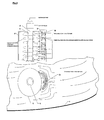
- Figure 3 shows another embodiment of the invention, on the top of the figure it is drawn schematically on the bottom of the figure 3 the embodiment is shown in an tank 2.
- the invention shows the pipe 4, surrounded by the second element 8 and the openings 6 for feeding the water into the tank.
- This embodiment has additional a shield 10.
- the shield can be of different shapes/forms. The shape/form should be designated so that the water jet streams are forced to bend and turn.
- the shield 10 surrounds the second element on that place, where the openings 6 are arranged. Shown is the circulation flow in the fish tank which is affected by the new element.
- the shield 10 surrounds the second element 8 or (not shown) the pipe 4 with a circumferential-angle of 60° to 200°, preferred 90° to 180°, this means between a quarter to one half.
- Figure 4 shows six different shields 10 which can be used for example according to the invention. All shields 10 are arranged in neighbourhood to the second element 8 and shield it against the flow in the fish tank. It can be adapted to the flow like the first example, or a segment of a circle like the second one.
- the third shows a rectangular shield 10.
- the fourth an acute-angled, the fifth a polygonal one.
- the last one shown has the rounded shape. It is shown that a lot of forms can be chosen by the man skilled in the art without departing from the invention.
Abstract
For a better adjustment of the flow a surrounding second element (8), having a plurality of openings (6), and/or a fixed or adjustable shield (10) are provided.
Description
- By rearing fish in tanks (closing rearing facilities for smolt and edible fish production), it is possible to exercise considerable control over the fish environment. However, the quality of the environment that can be created depends on several factors which, to a great extent, are mutually dependent.
- In an enclosed rearing facility, there is a complex interaction of the following factors:
- Temperature
- Illumination
- Density
- Oxygen Content
- Water flow rate
- Concentration level of refuse substances
- Food availability
- Current generation and velocity
- These factors are decisive for the biological and environmental behavior pattern of the fish.
- Not surprisingly, water is the most important factor in fish rearing. For example, a tank with a fish density of 60 kg of fish per cubic meter of water will consist of:
- 94 % water, by volume
- 6 % fish, by volume
- As a comparison, this is approximately the same density as observed in a crowded aircraft. Because of the cabin seat arrangement, the actual density within the aircraft is two to three times greater than the average value, without an adverse effect on comfort. Here, the cause may be that there was an abundance of fresh air and, on occasion, food is provided to each person at his/her seat, that is, without undue energy consumption and without eliciting aggressive behavior. Stated briefly, it is arranged to produce the best possible distribution of the most basic needs of our existence, with the aid of the aircraft's ventilation system and the cabin personnel.
- Supply distribution of oxygen and food are also key concepts in intensive fish rearing. In this type of distribution mechanism, water is used as the transport medium. Breeding tanks may be designed in such a way that the water flowing through the rearing unit is used in the most effective manner, with regard to the best possible environment for each of the fish.
- The invention is related to a inlet arrangement for fish tanks in Aquaculture, known as slot tube, water inlet arrangement, etc. Water means fresh water, aerated water or water enriched with oxygen.
- The brochure: "Fish rearing tanks, Aquaculture Series" of the AGA AB, S-18181 Lidingö, Sweden discloses some types of water inlet arrangements. Figure 13 shows a simple pipe nozzle or just a open water pipe. Figure 6 shows a vertical diffuser tube, Figure 7 a horizontal diffuser tube and Figure 8 a combination of vertical and horizontal diffuser tubes.
- The opening/openings of the inlet arrangement have fixed openings. There is no arrangement to adjust the water flow, water speed or water energy out of the inlet arrangement.
- Problems may be:
- Too high hydraulic energy or to low hydraulic energy coming out of the inlet arrangement
- Various hydraulic energy out of the openings of the inlet arrangement. The flow out of the pipe is larger at the bottom holes and lower at the upper holes.
- Suboptimal tank hydraulics with following results:
- Gradients of oxygen and metabolic wastes
- Reduced self cleaning of the fish tank
- Reduced distribution of food particles.
- It is the object of the invention to reduce the drawbacks of the state of the art.
- In especially:
- Achieve a good and homogenous circulation throughout the whole water column.
- Give self cleaning in the tank regarding waste products (faeces etc.).
- Good and even distribution of feed particles in the tank.
- Good and even distribution and mixing of oxygen in the tank.
- To be able to combine independently the circulation speed and water flow in a tank.
- To be able to increase efficiency of oxygenation processes.
- The object is solved by a water inlet arrangement with the features of claim 1. Embodiments of the invention and a process are subjects of the depending claims.
- The water inlet arrangement is built up from an inner pipe and an outer, surrounding tube or pipe. The parts are possible to disassemble to allow proper cleaning and disinfection. The holes/openings in the inner pipe "shoots" the water out in to the volume of the outer pipe and creates a circulation/rotation/turbulence. The water from the inner pipe hits the wall of the outer pipe at a given velocity (preferably at a velocity >2m/sec.). This forces the water to deflect and start an rotation/turbulens in the outer pipe before it flows out of the openings in the outer pipe. Instead of or additional to the surrounding pipe a shield can be used. A shield, surrounding only a part of the circumference of the pipe.
- The induced rotation prevents the gas bubbles in the water flow from combining to form larger gas bubbles (coalescence). This will increase efficiency and transfer speed between gas and liquid. The rotation and the design/placement of the holes/openings in the inner pipe will equalize the water pressure in the outer pipe. This will again create equal water flow/water speed/water energy from all the holes/openings in the outer pipe.
- The water inlet arrangement is constructed in such a way that the energy of the inlet water will not affect the force that is needed to rotate or adjust the direction of the water inlet arrangement around its own axis. This is to adjust the water current pattern in the tank.
- This is to adjust the direction of the flow, individually in each fish tank. It is desired to have a certain flexibility to adjust the flow/current pattern in a tank to each fish size/species and situation.
- The outer pipe is connected to the inner pipe by sealings or O-rings. This is done so that you can rotate the outer pipe around the inner pipe. Then the direction of the holes/openings in the outer pipe can be directed to a desired angel/direction in the fish tank. The pressure in the outer pipe is equal in all directions and results in a low torque requirement to rotate the outer pipe around the inner pipe.
- Speed and flow of the water can be adjusted independent. Maldeformation of fish by too high impact of hydraulic jets can be avoided.
- In large fish tanks of the state of the art the hydraulic energy is a problem when adjusting the direction of a slot tube. This is because hydraulic energy together with the area difference between the upper and lower end of the tube will result in a high down pressure. This pressure will increase the torque needed to rotate the inlet arrangement around it's own axis. With the invention one can easily eliminate the force this energy affect the torque needed to rotate the inlet arrangement.
- The invention has the following advantages:
- Easier directional flow adjustment of inlet flow by manual management of the water inlet device. Especially in large water flow and tank configurations where excessive hydraulic energy conditions exist.
- Possibility to adjust water flow and circulation speed independent of each other. The second element and/or the shield on the inlet arrangement together with the regulation valve to the fish tank allow to adjust to get an independent flow and circulation speed. This is done by regulating a given flow into a tank with the tank regulation valve. Then one adjusts the shield to the desirable circulation speed in the tank. As regulation of the shield will affect the water flow because of change in counter pressure it is important to compensate this change by adjusting the regulation valve accordingly.
The water speed from the shield and/or second element affects the existing water in the tank, and creates a circulation. When the speed is high out from the shield then the speed in the tank gets bigger. On a given flow one can decide the velocity in the tank by regulating the shield in/out from the outer pipe. This increases/reduces the area from which the water has to pass through, and also the speed of the water at a given flow.
It is possible to regulate the shield and regulation valve simultaneously to achieve the desired effect. - Reduce or take away deformities on fry/juveniles/larvae caused by water jet/jets from water inlet arrangement.
- Reduce degassing in the situation where over/super saturated water is introduced to a tank.
- Water inlet arrangement can be disassembled for cleaning and disinfection.
- The water inlet arrangement of the invention:
- Provides simpler handling and adjustment of the inlet stream flow direction, independent of the amount of flow into the tank. This can be done because the pressure inside the outer pipe is equal in all directions. The outer pipe can be rotated around the inner pipe and can therefore easily be turned as long as the pressure is equal in all directions. This is especially important when the dimensions and flow rate are large into the tank.
- Provides the flexibility to independently adjust water flow and water current in a tank with the adjustable shield.
- Provides equal water flow and energy throughout the whole water column in a tank. This is because the water pressure and flow is equalized between each of the holes/openings that are directed to the shield or water column.
- Prevents coalescence of gas bubbles because of high turbulence/rotation speed of the water within the outer pipe. This is especially important where oxygen or other gases are mixed in water in the form of small bubbles.
- Provides the mechanism to deliver the correct current in the tank for efficient dissolving and distribution of gases throughout the whole tank volume. It also enables effective removal of waste products such as faeces, ammonia and CO2.
- The pipe and/or the second element can have any shape as desired. It is of advantage, if they are cylindrical or have a polygonal cross section, like to triangle, a square, etc.. The openings can have a round shape, but also it is possible to form them in any shape like oval or rectangular slots. It is of advantage to have the openings arranged in one row for generating circulation in the fish tank in a simple manner.
- It is of advantage to orient the openings of the second element on the outside or in the shell of this element.
- In a preferred installation the openings of the first and the second element are not directed in the same direction. Preferably directed 180 dgr in relation to each other. This is done to create a turbulence inside the outer pipe, and to get as long as possible residence time between gas and water inside the outer pipe before it is introduced into the fishtank.
- In one preferred embodiment the water inlet arrangement is made with a fixed or an adjustable shield. The shield covers the water outlet holes/openings from the outer pipe of the water inlet arrangement. The shield deflects the water jets coming out of each hole/opening in the outer pipe of the water inlet arrangement. The water flow energy will be reduced as it hits the shield and the water flow is forced to spread and turn around to each side of the outer pipe of the water inlet arrangement.
- If the shield is adjustable so that the clearance dimension between the shield and outer pipe of the water inlet arrangement can be adjusted, this will result in controllable and adjustable water energy for a given water flow in to the tank. This means that one can individually adjust the water current and the water flow in the tank as required or as determined for the fish/organisms.
- The shield will increase the mixing zone between inlet and old/existing water in the tank. This is because the inlet water is introduced over a larger area and the contact between the existing tank water and the inlet water is greater than if it is introduced through holes directly in to the water volume. This way of introducing inlet water into a tank will contribute to lower gas/O2 gradients in the tank. This is important when water with high concentration of O2/gas is introduced in to a tank with living organisms.
- With the shield it provides the opportunity for self-cleaning of the tank, leading to improved hygiene, without having to include concentrated jet streams in to the water column. This is extremely important for breeding of fish and other organism that live in water, and that are sensitive to the physical strains caused by jet streams. As an example: Marine fish larvae (Cod, Sea bass, Sea bream).
- With the adjustable shield the flow in the tank can be affected in a desired manner. The shield can be broader or smaller than the surrounded element. In most cases the form of the shield corresponds to the form of the shielded element for enhancing the flow in the tank.
- The water inlet arrangement can be manufactured from various materials. Preferably made from non-corrosive materials such as polypropylene, polyethylene, glass fibre or polyvinyl chloride.
- Area of application can be in all situations where water is to be distributed in to a tank/pool/basin preferably in breeding of fish or other organisms living in water. The arrangement can be used for salt-water and for sweet-water. Marine and freshwater fishes can be reared with.
- The water inlet arrangement is especially well suited where water and gas are mixed before entering a fish tank.
- The invention is further described by four figures. They show:
-
Figure 1 : The state of the art -
Figure 2 : The embodiment of the invention -
Figure 3 : A second embodiment of the invention -
Figure 4 : Some examples of shields -
Figure 1 shows the state of the art. It is an water inlet arrangement, also called slot tube or inlet pipe with an water inlet on the top, a flange or brushing and a pipe with a row of openings. The water is fed into the tank through this pipe and the flow out of the tube or pipe is larger at the bottom holes and lower at the upper holes. The different speeds are an major drawback of this arrangement. -
Figure 2 shows an embodiment of a water inlet arrangement according to the invention. Thepipe 4 is coupled with a muff coupling to the water inlet. Thepipe 4 has a row ofopenings 6 for feeding the water into the now shown tank. Thepipe 4 is surrounded by thesecond element 8, which has here the form of an cylinder and has also a row ofopenings 6 for feeding the water into the tank. The turbulence/rotation is generated by the differing orientation of the rows of holes of both elements. -
Figure 3 shows another embodiment of the invention, on the top of the figure it is drawn schematically on the bottom of thefigure 3 the embodiment is shown in an tank 2. The invention shows thepipe 4, surrounded by thesecond element 8 and theopenings 6 for feeding the water into the tank. This embodiment has additional a shield 10.The shield can be of different shapes/forms. The shape/form should be designated so that the water jet streams are forced to bend and turn. Theshield 10 surrounds the second element on that place, where theopenings 6 are arranged. Shown is the circulation flow in the fish tank which is affected by the new element. Theshield 10 surrounds thesecond element 8 or (not shown) thepipe 4 with a circumferential-angle of 60° to 200°, preferred 90° to 180°, this means between a quarter to one half. -
Figure 4 shows sixdifferent shields 10 which can be used for example according to the invention. All shields 10 are arranged in neighbourhood to thesecond element 8 and shield it against the flow in the fish tank. It can be adapted to the flow like the first example, or a segment of a circle like the second one. The third shows arectangular shield 10. The fourth an acute-angled, the fifth a polygonal one. The last one shown has the rounded shape. It is shown that a lot of forms can be chosen by the man skilled in the art without departing from the invention.
Claims (8)
- Water inlet arrangement for the use in fish tanks (2) in aquaculture, with a pipe (4) to feed water into the tank (2), the pipe (4) having a plurality of openings (6), characterized by a surrounding second element (8), having a plurality of openings (6), and/or a fixed or adjustable shield (10).
- Water inlet arrangement according to claim 1, characterized by a cylindrical or polygonal cross section of the pipe (4) and/or the second element (8).
- Water inlet arrangement according to claim 1 or claim 2, characterized in that the openings (6) are arranged in one row.
- Water inlet arrangement according to one of the preceding claims, characterized in that the openings (6) of the second element (8) are arranged in the outside or in the shell of that element (8).
- Water inlet arrangement according to one of the preceding claims, characterized in that the openings (6) of the second element (8) are oriented in the same direction as the openings (6) of the first pipe (4).
- Water inlet arrangement according to one of the preceding claims, characterized by a fixed or adjustable shield (10) surrounding only a part of the circumference of the pipe (4) or the second element (8).
- Water inlet arrangement according to claim 6, characterized in that the shield (10) is arranged close to the openings (6) of the second element (8).
- Process for rearing fish with the step of feeding water into a fish tank by a water inlet arrangement as described in any of the preceding claims.
Priority Applications (16)
| Application Number | Priority Date | Filing Date | Title |
|---|---|---|---|
| EP07012719.6A EP2008513B1 (en) | 2007-06-28 | 2007-06-28 | Water inlet arrangement |
| DK07012719.6T DK2008513T3 (en) | 2007-06-28 | 2007-06-28 | Water inlet device |
| PT70127196T PT2008513E (en) | 2007-06-28 | 2007-06-28 | Water inlet arrangement |
| ES07012719.6T ES2550261T3 (en) | 2007-06-28 | 2007-06-28 | Water inlet arrangement |
| US12/664,082 US8707988B2 (en) | 2007-06-28 | 2008-05-06 | Water inlet arrangement |
| CA2687779A CA2687779C (en) | 2007-06-28 | 2008-05-06 | Water inlet arrangement |
| PCT/EP2008/003631 WO2009000361A2 (en) | 2007-06-28 | 2008-05-06 | Water inlet arrangement |
| AU2008267548A AU2008267548B2 (en) | 2007-06-28 | 2008-05-06 | Water inlet arrangement |
| BRPI0812967A BRPI0812967B1 (en) | 2007-06-28 | 2008-05-06 | water inlet setting |
| KR20097027620A KR20100029787A (en) | 2007-06-28 | 2008-05-06 | Water inlet arrangement |
| NZ580998A NZ580998A (en) | 2007-06-28 | 2008-05-06 | Water inlet arrangement comprising a pipe with holes that is surrounded by element with holes and a shield |
| CN200880022195A CN101686656A (en) | 2007-06-28 | 2008-05-06 | Water inlet arrangement |
| CL2008001929A CL2008001929A1 (en) | 2007-06-28 | 2008-06-27 | Water inlet arrangement for use in fish tanks in aquaculture, which has a pipe for feeding water into the tank and a second element that surrounds it and has a plurality of openings. |
| TNP2009000456A TN2009000456A1 (en) | 2007-06-28 | 2009-10-30 | Pyrido[2,3-d]pyrimidin-7-one compounds as inhibitors of pi3k-alpha for the treatment of cancer |
| ZA200907829A ZA200907829B (en) | 2007-06-28 | 2009-11-06 | Water inlet arrangement |
| US14/175,057 US9717219B2 (en) | 2007-06-28 | 2014-02-07 | Water inlet arrangement |
Applications Claiming Priority (1)
| Application Number | Priority Date | Filing Date | Title |
|---|---|---|---|
| EP07012719.6A EP2008513B1 (en) | 2007-06-28 | 2007-06-28 | Water inlet arrangement |
Publications (2)
| Publication Number | Publication Date |
|---|---|
| EP2008513A1 true EP2008513A1 (en) | 2008-12-31 |
| EP2008513B1 EP2008513B1 (en) | 2015-07-22 |
Family
ID=38796121
Family Applications (1)
| Application Number | Title | Priority Date | Filing Date |
|---|---|---|---|
| EP07012719.6A Active EP2008513B1 (en) | 2007-06-28 | 2007-06-28 | Water inlet arrangement |
Country Status (15)
| Country | Link |
|---|---|
| US (2) | US8707988B2 (en) |
| EP (1) | EP2008513B1 (en) |
| KR (1) | KR20100029787A (en) |
| CN (1) | CN101686656A (en) |
| AU (1) | AU2008267548B2 (en) |
| BR (1) | BRPI0812967B1 (en) |
| CA (1) | CA2687779C (en) |
| CL (1) | CL2008001929A1 (en) |
| DK (1) | DK2008513T3 (en) |
| ES (1) | ES2550261T3 (en) |
| NZ (1) | NZ580998A (en) |
| PT (1) | PT2008513E (en) |
| TN (1) | TN2009000456A1 (en) |
| WO (1) | WO2009000361A2 (en) |
| ZA (1) | ZA200907829B (en) |
Cited By (4)
| Publication number | Priority date | Publication date | Assignee | Title |
|---|---|---|---|---|
| EP2327298A1 (en) | 2009-11-13 | 2011-06-01 | Linde Aktiengesellschaft | Device for supplying gas into water |
| EP2534946A1 (en) | 2011-06-16 | 2012-12-19 | Linde Aktiengesellschaft | Method to reduce nitrogen concentration in salt water |
| US8707988B2 (en) | 2007-06-28 | 2014-04-29 | Linde Aktiengesellschaft | Water inlet arrangement |
| EP3766569A1 (en) | 2019-07-18 | 2021-01-20 | Linde GmbH | Apparatus for dissolving gas into a liquid and method for producing the same |
Families Citing this family (6)
| Publication number | Priority date | Publication date | Assignee | Title |
|---|---|---|---|---|
| US9421505B2 (en) * | 2013-03-11 | 2016-08-23 | Creative Water Solutions, Llc | Turbulent flow devices and methods of use |
| US11089789B2 (en) * | 2014-11-21 | 2021-08-17 | Tim McDonald | Apparatus for cleaning crustacea or game |
| CN106324277B (en) * | 2016-11-06 | 2019-09-03 | 宁波大学 | A kind of measuring method using indoor culture pond current surveying device |
| HRP20221199T1 (en) * | 2018-04-13 | 2023-01-06 | Andfjord Salmon AS | Efficient land-based fish farm |
| KR102019622B1 (en) * | 2019-01-11 | 2019-09-06 | 유한회사 테크놀로지트레이딩 | Dual pipe for equally dividing the amount of flowing water |
| KR102511226B1 (en) | 2022-08-03 | 2023-03-20 | 주식회사 선우하이테크 | Fishing tackle |
Citations (3)
| Publication number | Priority date | Publication date | Assignee | Title |
|---|---|---|---|---|
| US5055186A (en) * | 1988-01-21 | 1991-10-08 | Toever James W Van | Pellet media to support growth of microorganisms and systems for the utilization of same |
| US5421383A (en) | 1993-08-31 | 1995-06-06 | Schmid; Lawrence A. | Slide rail system for aeration diffusers and mixers |
| US20060192034A1 (en) * | 2005-02-22 | 2006-08-31 | Polylok, Inc., A Corporation Of The State Of Connecticut | Orifice shield for drainage pipe |
Family Cites Families (31)
| Publication number | Priority date | Publication date | Assignee | Title |
|---|---|---|---|---|
| US192034A (en) * | 1877-06-12 | Improvement in folding-machines | ||
| US2602465A (en) * | 1949-10-18 | 1952-07-08 | Otto C Goehring | Inlet tube for storage tanks and the like |
| US3601320A (en) * | 1968-06-26 | 1971-08-24 | Neil M Du Plessis | Apparatus for breaking up a directional fluid stream |
| GB1215187A (en) * | 1968-08-07 | 1970-12-09 | Struthers Scientific Int Corp | Diffuser for feed water heater |
| US3777987A (en) * | 1972-08-04 | 1973-12-11 | Allport Davies | Irrigation device |
| US3841999A (en) * | 1972-12-18 | 1974-10-15 | Syntex Inc | Process and apparatus for purifying and aerating aquaculture pools |
| US4215082A (en) * | 1975-02-25 | 1980-07-29 | Societe Anonyme dete: Alsthom-Atlantique | Device for injecting a gas into a liquid |
| BE854380R (en) * | 1976-05-25 | 1977-11-09 | Alsthom Atlantique | DEVICE FOR INJECTING A GAS INTO A LIQUID |
| FR2550469B1 (en) * | 1983-08-09 | 1985-10-04 | Alsthom Atlantique | MICROBUBBLE INJECTOR |
| US4915828A (en) | 1989-04-12 | 1990-04-10 | Raymond Meyers | Aquarium filter |
| US5066394A (en) * | 1990-07-30 | 1991-11-19 | Harrison Mark R | Aquarium aeration and recycling apparatus |
| US5174239A (en) * | 1991-05-21 | 1992-12-29 | Sato Kogei Kabushiki Kaisha | Sealed-type aquarium device |
| JP3161734B2 (en) | 1991-12-02 | 2001-04-25 | テクノロジカル リソーシィズ プロプライエタリー リミテッド | Reactor |
| JP2618326B2 (en) * | 1993-12-28 | 1997-06-11 | 有限会社オーディーアイ | Breeding method of saltwater fish and ornamental aquarium therefor |
| US5425723A (en) * | 1993-12-30 | 1995-06-20 | Boston Scientific Corporation | Infusion catheter with uniform distribution of fluids |
| AUPM714794A0 (en) * | 1994-07-29 | 1994-08-18 | International Fluid Separation Pty Limited | Separation apparatus and method |
| US5592969A (en) * | 1995-03-10 | 1997-01-14 | Reichert; Russell L. | Turbulence arrester |
| DE19540537C1 (en) * | 1995-10-31 | 1997-06-26 | Uhde Gmbh | Device for loading a solid bed |
| US6852232B2 (en) | 1996-05-23 | 2005-02-08 | John D. Martin | Down flow radial flow filter |
| US5782299A (en) | 1996-08-08 | 1998-07-21 | Purolator Products Company | Particle control screen assembly for a perforated pipe used in a well, a sand filter system and methods of making the same |
| US6488401B1 (en) * | 1998-04-02 | 2002-12-03 | Anthony E. Seaman | Agitators for wave-making or mixing as for tanks, and pumps and filters |
| NO317340B1 (en) | 2001-09-14 | 2004-10-11 | Oxseavision As | New oxygen oxygenation device |
| US6659043B1 (en) * | 2002-05-31 | 2003-12-09 | Gerard P. Huska | Aquarium water circulation system |
| US20040200427A1 (en) * | 2003-02-25 | 2004-10-14 | Neal Dulaney | Water flow system |
| US7011748B2 (en) * | 2004-03-31 | 2006-03-14 | Ting Feng Tsai | Water aerating and dirt collecting assembly for aquarium |
| US6912972B1 (en) * | 2004-04-09 | 2005-07-05 | Ting Feng Tsai | Water aerating device for aquarium |
| NO20042102A (en) | 2004-05-21 | 2005-05-30 | Aga As | Nozzle for oxygenation |
| JP2006136777A (en) | 2004-11-11 | 2006-06-01 | Maruwa Biochemical Co Ltd | Mixing apparatus for fine bubble |
| NO327035B1 (en) | 2007-06-11 | 2009-04-06 | Artec Aqua As | Aquarium Pool Setter |
| ES2550261T3 (en) | 2007-06-28 | 2015-11-05 | Linde Ag | Water inlet arrangement |
| PL2198704T3 (en) | 2008-12-19 | 2016-07-29 | Linde Ag | Oxygenating in aquaculture |
-
2007
- 2007-06-28 ES ES07012719.6T patent/ES2550261T3/en active Active
- 2007-06-28 EP EP07012719.6A patent/EP2008513B1/en active Active
- 2007-06-28 PT PT70127196T patent/PT2008513E/en unknown
- 2007-06-28 DK DK07012719.6T patent/DK2008513T3/en active
-
2008
- 2008-05-06 US US12/664,082 patent/US8707988B2/en active Active
- 2008-05-06 BR BRPI0812967A patent/BRPI0812967B1/en active IP Right Grant
- 2008-05-06 AU AU2008267548A patent/AU2008267548B2/en active Active
- 2008-05-06 NZ NZ580998A patent/NZ580998A/en not_active IP Right Cessation
- 2008-05-06 WO PCT/EP2008/003631 patent/WO2009000361A2/en active Application Filing
- 2008-05-06 KR KR20097027620A patent/KR20100029787A/en not_active Application Discontinuation
- 2008-05-06 CA CA2687779A patent/CA2687779C/en not_active Expired - Fee Related
- 2008-05-06 CN CN200880022195A patent/CN101686656A/en active Pending
- 2008-06-27 CL CL2008001929A patent/CL2008001929A1/en unknown
-
2009
- 2009-10-30 TN TNP2009000456A patent/TN2009000456A1/en unknown
- 2009-11-06 ZA ZA200907829A patent/ZA200907829B/en unknown
-
2014
- 2014-02-07 US US14/175,057 patent/US9717219B2/en active Active
Patent Citations (3)
| Publication number | Priority date | Publication date | Assignee | Title |
|---|---|---|---|---|
| US5055186A (en) * | 1988-01-21 | 1991-10-08 | Toever James W Van | Pellet media to support growth of microorganisms and systems for the utilization of same |
| US5421383A (en) | 1993-08-31 | 1995-06-06 | Schmid; Lawrence A. | Slide rail system for aeration diffusers and mixers |
| US20060192034A1 (en) * | 2005-02-22 | 2006-08-31 | Polylok, Inc., A Corporation Of The State Of Connecticut | Orifice shield for drainage pipe |
Cited By (7)
| Publication number | Priority date | Publication date | Assignee | Title |
|---|---|---|---|---|
| US8707988B2 (en) | 2007-06-28 | 2014-04-29 | Linde Aktiengesellschaft | Water inlet arrangement |
| US9717219B2 (en) | 2007-06-28 | 2017-08-01 | Linde Aktiengesellschaft | Water inlet arrangement |
| EP2327298A1 (en) | 2009-11-13 | 2011-06-01 | Linde Aktiengesellschaft | Device for supplying gas into water |
| US8556236B2 (en) | 2009-11-13 | 2013-10-15 | Linde Aktiengesellschaft | Device for supplying gas into water |
| AU2010241399B2 (en) * | 2009-11-13 | 2014-05-29 | Linde Aktiengesellschaft | Device for supplying gas into water |
| EP2534946A1 (en) | 2011-06-16 | 2012-12-19 | Linde Aktiengesellschaft | Method to reduce nitrogen concentration in salt water |
| EP3766569A1 (en) | 2019-07-18 | 2021-01-20 | Linde GmbH | Apparatus for dissolving gas into a liquid and method for producing the same |
Also Published As
| Publication number | Publication date |
|---|---|
| BRPI0812967B1 (en) | 2017-03-28 |
| TN2009000456A1 (en) | 2011-03-31 |
| WO2009000361A2 (en) | 2008-12-31 |
| US8707988B2 (en) | 2014-04-29 |
| AU2008267548B2 (en) | 2012-06-07 |
| US9717219B2 (en) | 2017-08-01 |
| NZ580998A (en) | 2012-02-24 |
| CL2008001929A1 (en) | 2009-09-25 |
| CA2687779A1 (en) | 2008-12-31 |
| WO2009000361A3 (en) | 2009-03-12 |
| ZA200907829B (en) | 2010-07-28 |
| BRPI0812967A2 (en) | 2014-12-16 |
| ES2550261T3 (en) | 2015-11-05 |
| US20100200069A1 (en) | 2010-08-12 |
| CA2687779C (en) | 2015-11-03 |
| US20140216558A1 (en) | 2014-08-07 |
| CN101686656A (en) | 2010-03-31 |
| PT2008513E (en) | 2015-11-02 |
| KR20100029787A (en) | 2010-03-17 |
| DK2008513T3 (en) | 2015-10-26 |
| AU2008267548A1 (en) | 2008-12-31 |
| EP2008513B1 (en) | 2015-07-22 |
Similar Documents
| Publication | Publication Date | Title |
|---|---|---|
| US9717219B2 (en) | Water inlet arrangement | |
| AU2010241399B2 (en) | Device for supplying gas into water | |
| US9392775B2 (en) | Fish culturing system | |
| KR101330704B1 (en) | Recirculating aquaculture system using air lift apparatus | |
| JP6399529B2 (en) | Perforated nozzle for killing harmful enemy aquatic creatures | |
| JP2016510600A (en) | Self-cleaning prefilter for water circulation pump | |
| KR20120020775A (en) | Ventury tube type nano bubble proceded water generator | |
| JP5150962B2 (en) | Crustacean breeding equipment | |
| JP2007159507A (en) | Shellfish culture tank and shellfish culture method | |
| WO2018211513A1 (en) | Method and system for maintaining water quality | |
| CN208387658U (en) | A kind of high-density aquiculture of independent loops purifying water process and keep-alive water tank | |
| WO2017094647A1 (en) | Swirl-flow gas-liquid mixing device for aquaculture | |
| KR101964802B1 (en) | Shrimp culture structure | |
| KR20100022879A (en) | Method and system for improving water and/or ground quality in farm of marine products | |
| KR102347019B1 (en) | The fluid supply pipe with twin venturi effect and aquaculture system equipped with an oxygen supply device for aquaculture organisms applying the same | |
| JP2004208613A (en) | Telescopic mixing-suppressing tool | |
| JP2021193946A (en) | Culture apparatus and culture method | |
| JPH1042740A (en) | Cultivating device for aquatic organism for feed and tool therefor | |
| WO2018048299A1 (en) | A water circulation system for aquatic animals and hatchery | |
| CN110637770A (en) | Fish culture equipment |
Legal Events
| Date | Code | Title | Description |
|---|---|---|---|
| PUAI | Public reference made under article 153(3) epc to a published international application that has entered the european phase |
Free format text: ORIGINAL CODE: 0009012 |
|
| AK | Designated contracting states |
Kind code of ref document: A1 Designated state(s): AT BE BG CH CY CZ DE DK EE ES FI FR GB GR HU IE IS IT LI LT LU LV MC MT NL PL PT RO SE SI SK TR |
|
| AX | Request for extension of the european patent |
Extension state: AL BA HR MK RS |
|
| 17P | Request for examination filed |
Effective date: 20090115 |
|
| 17Q | First examination report despatched |
Effective date: 20090220 |
|
| RAP1 | Party data changed (applicant data changed or rights of an application transferred) |
Owner name: LINDE AG |
|
| AKX | Designation fees paid |
Designated state(s): AT BE BG CH CY CZ DE DK EE ES FI FR GB GR HU IE IS IT LI LT LU LV MC MT NL PL PT RO SE SI SK TR |
|
| GRAP | Despatch of communication of intention to grant a patent |
Free format text: ORIGINAL CODE: EPIDOSNIGR1 |
|
| INTG | Intention to grant announced |
Effective date: 20150309 |
|
| GRAS | Grant fee paid |
Free format text: ORIGINAL CODE: EPIDOSNIGR3 |
|
| GRAA | (expected) grant |
Free format text: ORIGINAL CODE: 0009210 |
|
| AK | Designated contracting states |
Kind code of ref document: B1 Designated state(s): AT BE BG CH CY CZ DE DK EE ES FI FR GB GR HU IE IS IT LI LT LU LV MC MT NL PL PT RO SE SI SK TR |
|
| REG | Reference to a national code |
Ref country code: GB Ref legal event code: FG4D |
|
| REG | Reference to a national code |
Ref country code: CH Ref legal event code: EP |
|
| REG | Reference to a national code |
Ref country code: IE Ref legal event code: FG4D |
|
| REG | Reference to a national code |
Ref country code: AT Ref legal event code: REF Ref document number: 737342 Country of ref document: AT Kind code of ref document: T Effective date: 20150815 |
|
| REG | Reference to a national code |
Ref country code: DE Ref legal event code: R096 Ref document number: 602007042214 Country of ref document: DE |
|
| REG | Reference to a national code |
Ref country code: DK Ref legal event code: T3 Effective date: 20151020 |
|
| REG | Reference to a national code |
Ref country code: PT Ref legal event code: SC4A Free format text: AVAILABILITY OF NATIONAL TRANSLATION Effective date: 20151014 |
|
| REG | Reference to a national code |
Ref country code: ES Ref legal event code: FG2A Ref document number: 2550261 Country of ref document: ES Kind code of ref document: T3 Effective date: 20151105 |
|
| REG | Reference to a national code |
Ref country code: AT Ref legal event code: MK05 Ref document number: 737342 Country of ref document: AT Kind code of ref document: T Effective date: 20150722 |
|
| REG | Reference to a national code |
Ref country code: LT Ref legal event code: MG4D |
|
| REG | Reference to a national code |
Ref country code: NL Ref legal event code: FP |
|
| PG25 | Lapsed in a contracting state [announced via postgrant information from national office to epo] |
Ref country code: LT Free format text: LAPSE BECAUSE OF FAILURE TO SUBMIT A TRANSLATION OF THE DESCRIPTION OR TO PAY THE FEE WITHIN THE PRESCRIBED TIME-LIMIT Effective date: 20150722 Ref country code: LV Free format text: LAPSE BECAUSE OF FAILURE TO SUBMIT A TRANSLATION OF THE DESCRIPTION OR TO PAY THE FEE WITHIN THE PRESCRIBED TIME-LIMIT Effective date: 20150722 Ref country code: FI Free format text: LAPSE BECAUSE OF FAILURE TO SUBMIT A TRANSLATION OF THE DESCRIPTION OR TO PAY THE FEE WITHIN THE PRESCRIBED TIME-LIMIT Effective date: 20150722 |
|
| PG25 | Lapsed in a contracting state [announced via postgrant information from national office to epo] |
Ref country code: AT Free format text: LAPSE BECAUSE OF FAILURE TO SUBMIT A TRANSLATION OF THE DESCRIPTION OR TO PAY THE FEE WITHIN THE PRESCRIBED TIME-LIMIT Effective date: 20150722 Ref country code: PL Free format text: LAPSE BECAUSE OF FAILURE TO SUBMIT A TRANSLATION OF THE DESCRIPTION OR TO PAY THE FEE WITHIN THE PRESCRIBED TIME-LIMIT Effective date: 20150722 Ref country code: SE Free format text: LAPSE BECAUSE OF FAILURE TO SUBMIT A TRANSLATION OF THE DESCRIPTION OR TO PAY THE FEE WITHIN THE PRESCRIBED TIME-LIMIT Effective date: 20150722 |
|
| REG | Reference to a national code |
Ref country code: GR Ref legal event code: EP Ref document number: 20150402186 Country of ref document: GR Effective date: 20151209 |
|
| REG | Reference to a national code |
Ref country code: DE Ref legal event code: R097 Ref document number: 602007042214 Country of ref document: DE |
|
| PG25 | Lapsed in a contracting state [announced via postgrant information from national office to epo] |
Ref country code: SK Free format text: LAPSE BECAUSE OF FAILURE TO SUBMIT A TRANSLATION OF THE DESCRIPTION OR TO PAY THE FEE WITHIN THE PRESCRIBED TIME-LIMIT Effective date: 20150722 Ref country code: EE Free format text: LAPSE BECAUSE OF FAILURE TO SUBMIT A TRANSLATION OF THE DESCRIPTION OR TO PAY THE FEE WITHIN THE PRESCRIBED TIME-LIMIT Effective date: 20150722 Ref country code: CZ Free format text: LAPSE BECAUSE OF FAILURE TO SUBMIT A TRANSLATION OF THE DESCRIPTION OR TO PAY THE FEE WITHIN THE PRESCRIBED TIME-LIMIT Effective date: 20150722 |
|
| REG | Reference to a national code |
Ref country code: FR Ref legal event code: PLFP Year of fee payment: 10 |
|
| PLBE | No opposition filed within time limit |
Free format text: ORIGINAL CODE: 0009261 |
|
| STAA | Information on the status of an ep patent application or granted ep patent |
Free format text: STATUS: NO OPPOSITION FILED WITHIN TIME LIMIT |
|
| PG25 | Lapsed in a contracting state [announced via postgrant information from national office to epo] |
Ref country code: RO Free format text: LAPSE BECAUSE OF FAILURE TO SUBMIT A TRANSLATION OF THE DESCRIPTION OR TO PAY THE FEE WITHIN THE PRESCRIBED TIME-LIMIT Effective date: 20150722 |
|
| 26N | No opposition filed |
Effective date: 20160425 |
|
| PG25 | Lapsed in a contracting state [announced via postgrant information from national office to epo] |
Ref country code: SI Free format text: LAPSE BECAUSE OF FAILURE TO SUBMIT A TRANSLATION OF THE DESCRIPTION OR TO PAY THE FEE WITHIN THE PRESCRIBED TIME-LIMIT Effective date: 20150722 |
|
| PG25 | Lapsed in a contracting state [announced via postgrant information from national office to epo] |
Ref country code: BE Free format text: LAPSE BECAUSE OF FAILURE TO SUBMIT A TRANSLATION OF THE DESCRIPTION OR TO PAY THE FEE WITHIN THE PRESCRIBED TIME-LIMIT Effective date: 20150722 |
|
| PG25 | Lapsed in a contracting state [announced via postgrant information from national office to epo] |
Ref country code: MC Free format text: LAPSE BECAUSE OF FAILURE TO SUBMIT A TRANSLATION OF THE DESCRIPTION OR TO PAY THE FEE WITHIN THE PRESCRIBED TIME-LIMIT Effective date: 20150722 |
|
| REG | Reference to a national code |
Ref country code: FR Ref legal event code: PLFP Year of fee payment: 11 |
|
| REG | Reference to a national code |
Ref country code: FR Ref legal event code: PLFP Year of fee payment: 12 |
|
| PG25 | Lapsed in a contracting state [announced via postgrant information from national office to epo] |
Ref country code: HU Free format text: LAPSE BECAUSE OF FAILURE TO SUBMIT A TRANSLATION OF THE DESCRIPTION OR TO PAY THE FEE WITHIN THE PRESCRIBED TIME-LIMIT; INVALID AB INITIO Effective date: 20070628 Ref country code: CY Free format text: LAPSE BECAUSE OF FAILURE TO SUBMIT A TRANSLATION OF THE DESCRIPTION OR TO PAY THE FEE WITHIN THE PRESCRIBED TIME-LIMIT Effective date: 20150722 |
|
| PG25 | Lapsed in a contracting state [announced via postgrant information from national office to epo] |
Ref country code: LU Free format text: LAPSE BECAUSE OF NON-PAYMENT OF DUE FEES Effective date: 20160628 Ref country code: MT Free format text: LAPSE BECAUSE OF NON-PAYMENT OF DUE FEES Effective date: 20160630 |
|
| PG25 | Lapsed in a contracting state [announced via postgrant information from national office to epo] |
Ref country code: BG Free format text: LAPSE BECAUSE OF FAILURE TO SUBMIT A TRANSLATION OF THE DESCRIPTION OR TO PAY THE FEE WITHIN THE PRESCRIBED TIME-LIMIT Effective date: 20150722 |
|
| PGFP | Annual fee paid to national office [announced via postgrant information from national office to epo] |
Ref country code: DK Payment date: 20190613 Year of fee payment: 13 |
|
| PGFP | Annual fee paid to national office [announced via postgrant information from national office to epo] |
Ref country code: GB Payment date: 20190626 Year of fee payment: 13 |
|
| REG | Reference to a national code |
Ref country code: DE Ref legal event code: R081 Ref document number: 602007042214 Country of ref document: DE Owner name: LINDE GMBH, DE Free format text: FORMER OWNER: LINDE AG, 80331 MUENCHEN, DE |
|
| REG | Reference to a national code |
Ref country code: DE Ref legal event code: R119 Ref document number: 602007042214 Country of ref document: DE |
|
| REG | Reference to a national code |
Ref country code: DK Ref legal event code: EBP Effective date: 20200630 |
|
| REG | Reference to a national code |
Ref country code: CH Ref legal event code: PL |
|
| GBPC | Gb: european patent ceased through non-payment of renewal fee |
Effective date: 20200628 |
|
| PG25 | Lapsed in a contracting state [announced via postgrant information from national office to epo] |
Ref country code: FR Free format text: LAPSE BECAUSE OF NON-PAYMENT OF DUE FEES Effective date: 20200630 Ref country code: GB Free format text: LAPSE BECAUSE OF NON-PAYMENT OF DUE FEES Effective date: 20200628 Ref country code: CH Free format text: LAPSE BECAUSE OF NON-PAYMENT OF DUE FEES Effective date: 20200630 Ref country code: IE Free format text: LAPSE BECAUSE OF NON-PAYMENT OF DUE FEES Effective date: 20200628 Ref country code: LI Free format text: LAPSE BECAUSE OF NON-PAYMENT OF DUE FEES Effective date: 20200630 |
|
| PG25 | Lapsed in a contracting state [announced via postgrant information from national office to epo] |
Ref country code: DE Free format text: LAPSE BECAUSE OF NON-PAYMENT OF DUE FEES Effective date: 20210101 |
|
| PG25 | Lapsed in a contracting state [announced via postgrant information from national office to epo] |
Ref country code: DK Free format text: LAPSE BECAUSE OF NON-PAYMENT OF DUE FEES Effective date: 20200630 |
|
| P01 | Opt-out of the competence of the unified patent court (upc) registered |
Effective date: 20230523 |
|
| PGFP | Annual fee paid to national office [announced via postgrant information from national office to epo] |
Ref country code: PT Payment date: 20230621 Year of fee payment: 17 Ref country code: NL Payment date: 20230620 Year of fee payment: 17 |
|
| PGFP | Annual fee paid to national office [announced via postgrant information from national office to epo] |
Ref country code: TR Payment date: 20230621 Year of fee payment: 17 Ref country code: IS Payment date: 20230621 Year of fee payment: 17 Ref country code: GR Payment date: 20230616 Year of fee payment: 17 |
|
| PGFP | Annual fee paid to national office [announced via postgrant information from national office to epo] |
Ref country code: IT Payment date: 20230630 Year of fee payment: 17 Ref country code: ES Payment date: 20230719 Year of fee payment: 17 |