EP2007659B1 - Device for moving and orienting long tubular items - Google Patents
Device for moving and orienting long tubular items Download PDFInfo
- Publication number
- EP2007659B1 EP2007659B1 EP07733911.7A EP07733911A EP2007659B1 EP 2007659 B1 EP2007659 B1 EP 2007659B1 EP 07733911 A EP07733911 A EP 07733911A EP 2007659 B1 EP2007659 B1 EP 2007659B1
- Authority
- EP
- European Patent Office
- Prior art keywords
- item
- items
- feed
- links
- feed means
- Prior art date
- Legal status (The legal status is an assumption and is not a legal conclusion. Google has not performed a legal analysis and makes no representation as to the accuracy of the status listed.)
- Active
Links
Images


Classifications
-
- B—PERFORMING OPERATIONS; TRANSPORTING
- B65—CONVEYING; PACKING; STORING; HANDLING THIN OR FILAMENTARY MATERIAL
- B65G—TRANSPORT OR STORAGE DEVICES, e.g. CONVEYORS FOR LOADING OR TIPPING, SHOP CONVEYOR SYSTEMS OR PNEUMATIC TUBE CONVEYORS
- B65G19/00—Conveyors comprising an impeller or a series of impellers carried by an endless traction element and arranged to move articles or materials over a supporting surface or underlying material, e.g. endless scraper conveyors
- B65G19/02—Conveyors comprising an impeller or a series of impellers carried by an endless traction element and arranged to move articles or materials over a supporting surface or underlying material, e.g. endless scraper conveyors for articles, e.g. for containers
-
- B—PERFORMING OPERATIONS; TRANSPORTING
- B65—CONVEYING; PACKING; STORING; HANDLING THIN OR FILAMENTARY MATERIAL
- B65G—TRANSPORT OR STORAGE DEVICES, e.g. CONVEYORS FOR LOADING OR TIPPING, SHOP CONVEYOR SYSTEMS OR PNEUMATIC TUBE CONVEYORS
- B65G37/00—Combinations of mechanical conveyors of the same kind, or of different kinds, of interest apart from their application in particular machines or use in particular manufacturing processes
- B65G37/005—Combinations of mechanical conveyors of the same kind, or of different kinds, of interest apart from their application in particular machines or use in particular manufacturing processes comprising two or more co-operating conveying elements with parallel longitudinal axes
-
- B—PERFORMING OPERATIONS; TRANSPORTING
- B65—CONVEYING; PACKING; STORING; HANDLING THIN OR FILAMENTARY MATERIAL
- B65G—TRANSPORT OR STORAGE DEVICES, e.g. CONVEYORS FOR LOADING OR TIPPING, SHOP CONVEYOR SYSTEMS OR PNEUMATIC TUBE CONVEYORS
- B65G47/00—Article or material-handling devices associated with conveyors; Methods employing such devices
- B65G47/22—Devices influencing the relative position or the attitude of articles during transit by conveyors
- B65G47/24—Devices influencing the relative position or the attitude of articles during transit by conveyors orientating the articles
- B65G47/244—Devices influencing the relative position or the attitude of articles during transit by conveyors orientating the articles by turning them about an axis substantially perpendicular to the conveying plane
- B65G47/2445—Devices influencing the relative position or the attitude of articles during transit by conveyors orientating the articles by turning them about an axis substantially perpendicular to the conveying plane by means of at least two co-operating endless conveying elements
-
- B—PERFORMING OPERATIONS; TRANSPORTING
- B65—CONVEYING; PACKING; STORING; HANDLING THIN OR FILAMENTARY MATERIAL
- B65G—TRANSPORT OR STORAGE DEVICES, e.g. CONVEYORS FOR LOADING OR TIPPING, SHOP CONVEYOR SYSTEMS OR PNEUMATIC TUBE CONVEYORS
- B65G47/00—Article or material-handling devices associated with conveyors; Methods employing such devices
- B65G47/52—Devices for transferring articles or materials between conveyors i.e. discharging or feeding devices
- B65G47/56—Devices for transferring articles or materials between conveyors i.e. discharging or feeding devices to or from inclined or vertical conveyor sections
- B65G47/57—Devices for transferring articles or materials between conveyors i.e. discharging or feeding devices to or from inclined or vertical conveyor sections for articles
-
- B—PERFORMING OPERATIONS; TRANSPORTING
- B65—CONVEYING; PACKING; STORING; HANDLING THIN OR FILAMENTARY MATERIAL
- B65G—TRANSPORT OR STORAGE DEVICES, e.g. CONVEYORS FOR LOADING OR TIPPING, SHOP CONVEYOR SYSTEMS OR PNEUMATIC TUBE CONVEYORS
- B65G2201/00—Indexing codes relating to handling devices, e.g. conveyors, characterised by the type of product or load being conveyed or handled
- B65G2201/02—Articles
- B65G2201/0214—Articles of special size, shape or weigh
- B65G2201/0217—Elongated
-
- B—PERFORMING OPERATIONS; TRANSPORTING
- B65—CONVEYING; PACKING; STORING; HANDLING THIN OR FILAMENTARY MATERIAL
- B65G—TRANSPORT OR STORAGE DEVICES, e.g. CONVEYORS FOR LOADING OR TIPPING, SHOP CONVEYOR SYSTEMS OR PNEUMATIC TUBE CONVEYORS
- B65G2201/00—Indexing codes relating to handling devices, e.g. conveyors, characterised by the type of product or load being conveyed or handled
- B65G2201/02—Articles
- B65G2201/0276—Tubes and pipes
Definitions
- This invention relates to a device for moving and, in particular for orienting long items along a curved section as disclosed for example in DE-U-20 2005 008312
- a device for moving and, in particular for orienting long items according to claim 1.
- These items are tubular cores made of card used for making rolls, preferably rolls of toilet or kitchen paper.
- Each long item has a longitudinal axis and opposite ends.
- Each item is fed forward while keeping it substantially transversal to the direction of feed and fed out of the device at a suitable angle.
- the items are accompanied as they proceed along the curved section, enabling high feed speeds to be attained and/or reducing the risk of damaging the items.
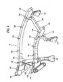
- FIG. 1 illustrates a preferred embodiment 10 of a device according to the invention for orienting long items, where said items are tubular cores 11 made of card for supporting paper, preferably toilet or kitchen paper.
- the device according to the invention comprises means for imparting to each item an angular movement, labelled "A" in Figure 1 , such that the item 11 is suitably oriented when it is fed out of the device.
- the long item is conveniently supported and does not run the risk of bending as it advances, in particular along the horizontal path.
- the long item may be conveniently advanced at high speeds without the risk of being damaged.
- the first and second feed means take the form of respective endless conveyors 12, 14, each composed of a plurality of links articulated to each other and mounted on a respective frame 121, 141, forming a respective conveyor path.
- each mounting frame 121, 141 forms an initial straight section for the respective first and second conveyor 12 and 14 and a straight terminal section for the conveyors 12, 14.
- the feeding means 16 also comprises means, not illustrated in detail in the drawings, for sequentially releasing the long items 11 in such a way as to transfer them to the conveyors 12, 14 one at a time.
- the protruding elements each take the form of a substantially flat, quadrangular protruding element 126, 146.
- first and second feed means 12, 14 comprise respective pluralities of elements 126, 146, equally spaced in the longitudinal feed direction, for engaging the backs of the items 11.
- the back engagement elements 126 of the first feed means 12 are separated from each other by a certain number of links, while the back engagement elements 146 of the second feed means 14 are separated from each other by a predetermined number of links smaller than the number of links separating the back engagement elements 126 of the first feed means 12.
- the means for lifting the tubular card cores 11 comprise respective rear engagement elements 181 for lifting the items 11 and extending outside the respective chute 17.
- the mounting frame of the conveyors 12 and 14 comprises respective floor supporting columns 121', 141' and supporting crossbars, labelled 150, connecting opposite side columns 121', 141'.
- the transmission means 24 comprise, like the transmission means 26 of the first conveyor 12, a transmission belt 240 trained around respective pulleys 242, 244.
- a chain and sprocket system might also be used.
Abstract
Description
- This invention relates to a device for moving and, in particular for orienting long items along a curved section as disclosed for example in
DE-U-20 2005 008312 - . More specifically, the items are tubular cores made of card, used for making rolls, preferably rolls of toilet or kitchen paper (See e.g.
WO-A-2004/005172 ). - In the tissue paper industry, especially in the production of rolls of toilet or kitchen paper, floor space in production facilities is a very important factor taken into consideration when planning machinery layout. To save space, the machines for making the tubular card cores for the rolls are oriented at an angle to the rewinding machine or system that winds the paper onto the tubular cores.
- In particular, prior art teaches the use of devices for orienting tubular cores made of card, used for making rolls, preferably rolls of toilet or kitchen paper. These devices comprise means for imparting an angular movement to the long items in such a way that they are fed out of the device at a suitable angle. For transferring the tubular card cores, which are relatively long and easily damaged, the angular orienting means comprise means that receive the card cores from a chute on which they are fed out of the machine that makes them. These receiving means comprise a conveyor belt, on the outer side of the curved section along which the tubular cores move, and a fixed plate for engaging the ends of the tubular cores and located on the inner side of the curved section along which the tubular cores move.
- This type of device for orienting long items or cores, however, has the drawback of not allowing high conveying speeds to be reached. When the conveying speed is increased, the card cores are subjected to high accelerations tending to move them out of position so they are incorrectly aligned when they reach the transfer point downstream, at the feed magazine of the paper roll rewinding machine.
- Moreover, the card for making the cores is not very resistant, so the cores are easily damaged. In particular, the rolling action the cores are subjected to, according to prior art, in order to orient them may lead to severe scratching and scoring on the surface of the cores, causing damaged items to be rejected.
- According to an advantageous aspect a device is provided for moving and, in particular for orienting long items according to claim 1. These items are tubular cores made of card used for making rolls, preferably rolls of toilet or kitchen paper. Each long item has a longitudinal axis and opposite ends. Each item is fed forward while keeping it substantially transversal to the direction of feed and fed out of the device at a suitable angle.
- The device comprises first mobile means for feeding a corresponding portion of the item and extending along a respective path, which has a curved section, and second mobile means for feeding a second portion of the item and extending along a respective path having a curved section which is concentric with and radially inside the curved section of the first mobile means.
- Thus, the items are accompanied as they proceed along the curved section, enabling high feed speeds to be attained and/or reducing the risk of damaging the items.
- In particular, the long item is prevented from rolling on its own axis, which reduces the risk of unwanted scoring on the surface.
- These and other technical characteristics of present device are clearly described in the claims below and its advantages are apparent from the detailed description which follows, with reference to the accompanying drawings which illustrate a preferred embodiment of the invention provided merely by way of example without restricting the scope of the inventive concept, and in which:
-
Figure 1 is a top view of a preferred embodiment of the device according to the invention; -
Figure 2 is a schematic side view showing the rear portion of the preferred embodiment of the device according to the invention; -
Figure 3 is a side view showing the transfer, or end, portion of the preferred embodiment of the device according to the invention; -
Figure 4 is a perspective view of the preferred embodiment of the device, according to the invention detached from the preferred context in which it is used; -
Figure 5 is a schematic side view of the end portion of the preferred embodiment of the device according to the invention, showing the drive means in particular; -
Figure 6 is a side view, partly in cross section, showing the end drive portion of the preferred embodiment of the device according to the invention. - The accompanying drawings illustrate a
preferred embodiment 10 of a device according to the invention for orienting long items, where said items aretubular cores 11 made of card for supporting paper, preferably toilet or kitchen paper. - As illustrated, the long item, or core, 11 extends mainly lengthways along an axis "L" between two
opposite ends - The device according to the invention comprises means for imparting to each item an angular movement, labelled "A" in
Figure 1 , such that theitem 11 is suitably oriented when it is fed out of the device. - The reference character "F" in
Figure 1 denotes arrows indicating the feed direction of the items at the respective positions. - The means for the angular orientation of the
item 11 are designed to cause the item to be fed forward while keeping it substantially transversal to the direction of feed at the specific point. - In this way, operations can be performed even at high speed without the risk of damaging the tubular card core.
- In practice, this prevents the tubular core from rolling and thus scoring its surface.
- More specifically, the
ends - First mobile means 12 are provided for feeding a corresponding portion of the
item 11 and extending along a respective path, which has acurved section 12a, and second mobile means 14 are provided for feeding a second portion of theitem 11 and extending along a respective path having acurved section 14a which is concentric with and radially inside thecurved section 12a of the first mobile feed means with reference to the centre of rotation "C". - As illustrated, in particular in
Figure 1 , thefirst means 12 for feeding theitem 11 are adapted to engage a respectiveintermediate portion 11c of the item and thesecond means 14 for feeding theitem 11 are in turn adapted to engage a respectiveintermediate portion 11d of the item, theseintermediate portions respective ends item 11. - In this way, the long item is conveniently supported and does not run the risk of bending as it advances, in particular along the horizontal path.
- In particular, the long item may be conveniently advanced at high speeds without the risk of being damaged.
- In particular, as illustrated, the distance between the
portion 11c engaged by the first feed means 12 and therespective end 11b is approximately one third of the length "H" of theitem 11, and the distance between theportion 11d engaged by the second feed means 14 and therespective end 11a of thetubular item 11 is also approximately one third of the length, which means that the distance "D" between the first and the second feed means 12 and 14 is substantially one third of the length of theitem 11. Since the cores normally vary in length from 2500mm to 3000 mm, the feed means 12 and 14 are preferably around 900 mm apart. - This provides optimum support for the long item.
- In this way, the tubular item, which is made of card and is therefore easily deformed, can be transported or moved along a curved path even at high speeds without deforming or damaging it.
- As illustrated, the first and second feed means 12, 14 are designed to receive and support the underside of the
items 11, which move along a mainly horizontal path. - As illustrated, the first and second feed means take the form of respective
endless conveyors respective frame - The
conveyors WO 2005/009874 in the name of the same applicant, where the conveyor consists of a plurality of links made of rigid plastic and suitably articulated to each other. - More specifically, each
mounting frame second conveyor conveyors - In
Figure 1 , thenumerals respective conveyors numerals conveyors - The
curved sections straight sections straight sections respective conveyors - As illustrated, the first and second feed means 12, 14 comprise respective upward sloping sections corresponding to the
terminal sections frames - As illustrated, upstream of this conveying device, there are
means 16 for feeding thecard tubes 11 out of a respective machine where the tube is made from respective rolls of card, the feeding means 16 comprising a downward sloping chute 16' having anend 163 that extends between theconveyors numerals - The feeding means 16 also comprises means, not illustrated in detail in the drawings, for sequentially releasing the
long items 11 in such a way as to transfer them to theconveyors - The first and second feed means of the device according to the invention comprise means 126, 146 for engaging the backs of the
items 11. - More specifically, the back engagement means 126, 146 take the form of respective elements, each integral with and protruding from the upper surface of a link forming part of the
conveyors - The protruding elements each take the form of a substantially flat, quadrangular
protruding element - In particular, as illustrated, the first and second feed means 12, 14 comprise respective pluralities of
elements items 11. - The
back engagement elements 126 of the first feed means 12 are separated from each other by a certain number of links, while theback engagement elements 146 of the second feed means 14 are separated from each other by a predetermined number of links smaller than the number of links separating theback engagement elements 126 of the first feed means 12. - As shown in
Figure 2 , the first and secondback engagement elements items 11 at an upward sloping, or lifting, section and, more specifically, at a respective transfer wheel at the upstream end of the first and second feed means 12, 14. - At the downstream end, the engagement means 126, 146 push and allow the
long items 11 to slide onto achute 17 which slopes downwards and transfers theitems 11 to the infeed end ofrespective means 18 that lift and transport them towards a feed magazine of the rewinding machine or system which makes the paper rolls, in particular, rolls of kitchen or toilet paper. - As illustrated, the means for lifting the
tubular card cores 11 comprise respectiverear engagement elements 181 for lifting theitems 11 and extending outside therespective chute 17. - The
reference numeral 182 denotes means for guiding and retaining thetubular items 11 on thehorizontal slats 181 of the respective means that lift and transport them to the feed magazine of the paper roll rewinding machine. - As illustrated, the mounting frame of the
conveyors - As shown in
Figure 3 , the point where theitems 11 are transferred is at substantially the same height as the horizontal surface on which they are conveyed by the feed means. The transfer end of the chute is labelled 17a inFigure 3 . - Means are also provided for driving the first and
second conveyors Figures 5 and6 , designed to rotationally drive atransversal shaft 22 which is in turn connected through respective transmission means 24, 26 to the drive wheels of theconveyors - More specifically, the transmission means 24 comprise, like the transmission means 26 of the
first conveyor 12, atransmission belt 240 trained aroundrespective pulleys - In particular, the toothed wheels or sprockets engaging the links of the
conveyors respective engagement element engagement elements - According to one preferred embodiment, there are ten links defining the spacing between two
consecutive engagement elements 126 on theouter conveyor 12, and seven links defining the spacing between twoconsecutive engagement elements 146 on theinner conveyor 14. The drive wheel of theouter conveyor 12 therefore has twenty teeth, while the drive wheel of theinner conveyor 14 has fourteen teeth. - A drive system that is easy to assemble and set up is thus obtained.
- In practice, the first and
second conveyor
Claims (12)
- A device (10) for moving and orienting long items (11), these items being tubular cores made of card, used for making rolls, preferably rolls of toilet or kitchen paper; each long item having a longitudinal axis (L) and opposite ends (11a, 11b), the device comprising first mobile means (12) for feeding an intermediate portion (11c) of each item (11) and extending along a respective path, which has a curved section (12a), and second mobile means (14) for feeding a second intermediate portion (11d) of each item (11) and extending along a respective path having a curved section (14a) which is concentric with and radially inside the curved section (12a) of the first mobile means (12) characterised in that said first and second mobile means (12,14) are endless conveyors comprising, means (126, 146) for engaging the backs of the items (11), each conveyor being composed of a plurality of links articulated to each other and mounted on a respective frame (121, 141), forming a respective conveyor path, said means for engaging the backs of the items comprising respective protruding element a (126, 146) extending from respective links of the first and second conveyor and being each integral with and protruding from the upper surface of a respective link forming part of the respective conveyor (12, 14), said back engagement, elements (126) of the first mobile means (12) being separated from each other by a predetermined number of links, and said back engagement elements (146) of the second mobile means (14) being separated from each other by a predetermined number of links smaller than the number of links separating the back engagement elements (126) of the first mobile means (12), so that the axis (L) of the long item (11) is angularly moved and the item is fed forward while keeping it substantially transversal to the direction of feed (F) and is fed out of the device at a suitable angle.
- The device according to claim 1, characterised in that the distance (D) between the first and second feed means (12, 14) is substantially one third of the length of the item (11).
- The device according to any of the foregoing claims, characterised in that the first and second feed means (12, 14) support the bottoms of the items (11).
- The device according to any of the foregoing claims, characterised in that the first and second feed means (12, 14) feed the items along a mainly horizontal path.
- The device according to any of the foregoing claims, characterised in that the first and second feed means (12, 14) have at least one straight section.
- The device according to claim 5, characterised in that the first and second feed means (12, 14) have at the upstream end a straight section (123, 143).
- The device according to claim 5 or 6, characterised in that the first and second feed means (12, 14) have at the downstream end a straight section (124, 144).
- The device according to claims 6 and 7, characterised in that the curved section (12a, 14a) of the first and second feed means (12, 14) extends between the upstream straight section (123, 143) and the downstream straight section (124, 144).
- The device according to any of the foregoing claims, characterised in that the first and second feed means (12, 14) have an upward sloping section (124, 144).
- The device according to claim 9, characterised in that the first and second feed means (12, 14) have at the downstream end an upward sloping section (124, 144).
- The device according to any of the foregoing claims, characterised in that it comprises means for driving the first and second conveyor (12, 14) having a single drive motor (20) designed to rotationally drive a transversal shaft (22) which ls in turn connected through respective transmission means (24, 26) to drive wheels of the conveyors (12, 14).
- The device according to claim 11, characterised in that it comprises toothed wheels or sprockets engaging the links of the conveyors (12, 14) having a different number of teeth.
Priority Applications (1)
| Application Number | Priority Date | Filing Date | Title |
|---|---|---|---|
| PL07733911T PL2007659T3 (en) | 2006-03-31 | 2007-03-05 | Device for moving and orienting long tubular items |
Applications Claiming Priority (2)
| Application Number | Priority Date | Filing Date | Title |
|---|---|---|---|
| IT000234A ITBO20060234A1 (en) | 2006-03-31 | 2006-03-31 | DEVICE FOR ORIENTATION OF EXTENDED ITEMS. |
| PCT/IB2007/000505 WO2007116251A2 (en) | 2006-03-31 | 2007-03-05 | Device for moving, in particular for orienting long items |
Publications (2)
| Publication Number | Publication Date |
|---|---|
| EP2007659A2 EP2007659A2 (en) | 2008-12-31 |
| EP2007659B1 true EP2007659B1 (en) | 2014-01-29 |
Family
ID=38512534
Family Applications (1)
| Application Number | Title | Priority Date | Filing Date |
|---|---|---|---|
| EP07733911.7A Active EP2007659B1 (en) | 2006-03-31 | 2007-03-05 | Device for moving and orienting long tubular items |
Country Status (5)
| Country | Link |
|---|---|
| US (1) | US7837023B2 (en) |
| EP (1) | EP2007659B1 (en) |
| IT (1) | ITBO20060234A1 (en) |
| PL (1) | PL2007659T3 (en) |
| WO (1) | WO2007116251A2 (en) |
Cited By (1)
| Publication number | Priority date | Publication date | Assignee | Title |
|---|---|---|---|---|
| CN112278770A (en) * | 2020-11-14 | 2021-01-29 | 邓权塑业科技(湖南)有限公司 | Falling and landing prevention device for large-diameter pipes |
Families Citing this family (2)
| Publication number | Priority date | Publication date | Assignee | Title |
|---|---|---|---|---|
| CN105668117B (en) * | 2016-04-06 | 2018-07-24 | 苏州奥然日用品有限公司 | A kind of feeding device of foot pedal kludge |
| US10829313B2 (en) | 2018-08-02 | 2020-11-10 | Intelligrated Headquarters, Llc | Goods to operator workstation |
Family Cites Families (14)
| Publication number | Priority date | Publication date | Assignee | Title |
|---|---|---|---|---|
| US1206305A (en) * | 1915-03-22 | 1916-11-28 | Lamson Co | Corner for conveyers. |
| US1930318A (en) * | 1932-04-04 | 1933-10-10 | Mojonnier Bros Co | Distributing conveyer |
| US3367474A (en) * | 1965-10-08 | 1968-02-06 | Douglas M. Kerr | Conveyor apparatus |
| US3509984A (en) * | 1968-05-06 | 1970-05-05 | Union Steel Products Co | Article orienting conveyor |
| US3690443A (en) * | 1970-10-12 | 1972-09-12 | Teledyne Inc | Turn conveyor |
| GB2067494B (en) * | 1980-01-15 | 1984-01-18 | Turkington J F Conveyors | Endless conveyors |
| JPH06271030A (en) | 1993-03-21 | 1994-09-27 | Tamura Kikai Seisakusho:Kk | Curve conveyor |
| ES1030933Y (en) * | 1995-04-26 | 1996-04-01 | Alba Adelardo Lopez | DOUBLE BRANCH TRANSPORT DEVICE. |
| US5673784A (en) * | 1995-08-17 | 1997-10-07 | Food Process Systems, Inc. | Plural preformed belt conveyor corner turn |
| DE10135591A1 (en) * | 2001-07-20 | 2003-01-30 | Bosch Gmbh Robert | Curve section for conveyor system comprises curved outer rail, inner section of curve being made up of two straight rails which project beyond imaginary curve running along central axis of the section |
| ITBG20010047A1 (en) | 2001-12-21 | 2003-06-21 | Micromec S N C Di Marchesi & C | MOTORIZED CURVE FOR FLAT LINES FOR THE TRANSPORT OF OBJECTS WITH A FLAT BOTTOM, PARTICULARLY BOOKS. |
| ITFI20020122A1 (en) | 2002-07-09 | 2004-01-09 | Perini Fabio Spa | REWINDING MACHINE FOR THE PRODUCTION OF ROLLS OF WRAPPED WIRE AND RELATED METHOD |
| DE202005008312U1 (en) | 2005-05-24 | 2005-07-28 | Knapp Logistik Automation Ges.M.B.H. | Curved conveyor has profiled endless belts on either side, on which articles to be transported rest, belts being mounted on rollers at either end, one of which is connected to motor |
| NL1029294C2 (en) | 2005-06-20 | 2006-12-22 | Blueprint Automation B V | Curved path conveyor for e.g. French stick bread, has transport plane located in between conveyor chains to ensure orientation of transported goods remains unchanged |
-
2006
- 2006-03-31 IT IT000234A patent/ITBO20060234A1/en unknown
-
2007
- 2007-03-05 US US12/295,295 patent/US7837023B2/en not_active Expired - Fee Related
- 2007-03-05 EP EP07733911.7A patent/EP2007659B1/en active Active
- 2007-03-05 WO PCT/IB2007/000505 patent/WO2007116251A2/en active Application Filing
- 2007-03-05 PL PL07733911T patent/PL2007659T3/en unknown
Cited By (1)
| Publication number | Priority date | Publication date | Assignee | Title |
|---|---|---|---|---|
| CN112278770A (en) * | 2020-11-14 | 2021-01-29 | 邓权塑业科技(湖南)有限公司 | Falling and landing prevention device for large-diameter pipes |
Also Published As
| Publication number | Publication date |
|---|---|
| EP2007659A2 (en) | 2008-12-31 |
| ITBO20060234A1 (en) | 2007-10-01 |
| US7837023B2 (en) | 2010-11-23 |
| PL2007659T3 (en) | 2014-07-31 |
| WO2007116251A2 (en) | 2007-10-18 |
| US20090178903A1 (en) | 2009-07-16 |
| WO2007116251A3 (en) | 2007-12-21 |
Similar Documents
| Publication | Publication Date | Title |
|---|---|---|
| US7631744B2 (en) | Device for transporting printed products | |
| JP5632743B2 (en) | Accumulation and release conveyor | |
| EP2000426B1 (en) | Stock conveyer | |
| EP1866222B1 (en) | Methods and apparatus for removing holes from nested product patterns | |
| JP2013517192A (en) | Inverted measuring belt conveyor | |
| EP2895409B1 (en) | Belt conveyor system, roller-engagement mechanism, and related method | |
| JP2553999B2 (en) | Method and device for side-by-side conveyance of articles | |
| CN101821178A (en) | Belt conveyors with retractable wall segments | |
| NL2009721C2 (en) | FINAL DRIVE FOR A TRANSPORTER, TRANSPORTED WITH AN END DRIVE, AND DRIVE GEAR FOR AN END DRIVE. | |
| EP1845039B1 (en) | Dynamic temporary article storing device, for example for syringes | |
| JP4828801B2 (en) | Method of changing the direction of conveyed items on a conveyor | |
| EP2007659B1 (en) | Device for moving and orienting long tubular items | |
| JP4886451B2 (en) | Outfeed mechanism for star wheel type glass inspection machine | |
| US8167119B2 (en) | Low-pressure accumulation system | |
| JP3895726B2 (en) | Origami stacker | |
| US9938031B2 (en) | Method of processing a plurality of articles through a processing section of a packaging machine and method of reconfiguring a processing section of a packaging machine | |
| KR930005024B1 (en) | Apparatus for arraying and conveying web-like material | |
| JP5537834B2 (en) | Container delivery device | |
| JP4216954B2 (en) | Direction change device | |
| JP3370763B2 (en) | Long material combination equipment | |
| JP4786055B2 (en) | Article alignment device | |
| KR20090099976A (en) | Apparatus for transferring products and apparatus for packing products having the same | |
| MXPA05001921A (en) | Device and method for positioning separately supplied elongate meat products. | |
| EP1852370B1 (en) | Conveyor for organising items | |
| JPH0316817Y2 (en) |
Legal Events
| Date | Code | Title | Description |
|---|---|---|---|
| PUAI | Public reference made under article 153(3) epc to a published international application that has entered the european phase |
Free format text: ORIGINAL CODE: 0009012 |
|
| 17P | Request for examination filed |
Effective date: 20080930 |
|
| AK | Designated contracting states |
Kind code of ref document: A2 Designated state(s): AT BE BG CH CY CZ DE DK EE ES FI FR GB GR HU IE IS IT LI LT LU LV MC MT NL PL PT RO SE SI SK TR |
|
| AX | Request for extension of the european patent |
Extension state: AL BA HR MK RS |
|
| 17Q | First examination report despatched |
Effective date: 20090122 |
|
| R17C | First examination report despatched (corrected) |
Effective date: 20090529 |
|
| RTI1 | Title (correction) |
Free format text: DEVICE FOR MOVING AND ORIENTING LONG TUBULAR ITEMS |
|
| GRAP | Despatch of communication of intention to grant a patent |
Free format text: ORIGINAL CODE: EPIDOSNIGR1 |
|
| GRAJ | Information related to disapproval of communication of intention to grant by the applicant or resumption of examination proceedings by the epo deleted |
Free format text: ORIGINAL CODE: EPIDOSDIGR1 |
|
| DAX | Request for extension of the european patent (deleted) | ||
| GRAP | Despatch of communication of intention to grant a patent |
Free format text: ORIGINAL CODE: EPIDOSNIGR1 |
|
| GRAS | Grant fee paid |
Free format text: ORIGINAL CODE: EPIDOSNIGR3 |
|
| GRAA | (expected) grant |
Free format text: ORIGINAL CODE: 0009210 |
|
| AK | Designated contracting states |
Kind code of ref document: B1 Designated state(s): AT BE BG CH CY CZ DE DK EE ES FI FR GB GR HU IE IS IT LI LT LU LV MC MT NL PL PT RO SE SI SK TR |
|
| REG | Reference to a national code |
Ref country code: GB Ref legal event code: FG4D |
|
| REG | Reference to a national code |
Ref country code: CH Ref legal event code: EP |
|
| REG | Reference to a national code |
Ref country code: AT Ref legal event code: REF Ref document number: 651459 Country of ref document: AT Kind code of ref document: T Effective date: 20140215 |
|
| REG | Reference to a national code |
Ref country code: IE Ref legal event code: FG4D |
|
| REG | Reference to a national code |
Ref country code: DE Ref legal event code: R096 Ref document number: 602007034992 Country of ref document: DE Effective date: 20140306 |
|
| REG | Reference to a national code |
Ref country code: NL Ref legal event code: VDEP Effective date: 20140129 |
|
| REG | Reference to a national code |
Ref country code: LT Ref legal event code: MG4D |
|
| PG25 | Lapsed in a contracting state [announced via postgrant information from national office to epo] |
Ref country code: IS Free format text: LAPSE BECAUSE OF FAILURE TO SUBMIT A TRANSLATION OF THE DESCRIPTION OR TO PAY THE FEE WITHIN THE PRESCRIBED TIME-LIMIT Effective date: 20140529 Ref country code: LT Free format text: LAPSE BECAUSE OF FAILURE TO SUBMIT A TRANSLATION OF THE DESCRIPTION OR TO PAY THE FEE WITHIN THE PRESCRIBED TIME-LIMIT Effective date: 20140129 |
|
| REG | Reference to a national code |
Ref country code: PL Ref legal event code: T3 |
|
| PG25 | Lapsed in a contracting state [announced via postgrant information from national office to epo] |
Ref country code: ES Free format text: LAPSE BECAUSE OF FAILURE TO SUBMIT A TRANSLATION OF THE DESCRIPTION OR TO PAY THE FEE WITHIN THE PRESCRIBED TIME-LIMIT Effective date: 20140129 Ref country code: SE Free format text: LAPSE BECAUSE OF FAILURE TO SUBMIT A TRANSLATION OF THE DESCRIPTION OR TO PAY THE FEE WITHIN THE PRESCRIBED TIME-LIMIT Effective date: 20140129 Ref country code: CY Free format text: LAPSE BECAUSE OF FAILURE TO SUBMIT A TRANSLATION OF THE DESCRIPTION OR TO PAY THE FEE WITHIN THE PRESCRIBED TIME-LIMIT Effective date: 20140129 Ref country code: FI Free format text: LAPSE BECAUSE OF FAILURE TO SUBMIT A TRANSLATION OF THE DESCRIPTION OR TO PAY THE FEE WITHIN THE PRESCRIBED TIME-LIMIT Effective date: 20140129 Ref country code: NL Free format text: LAPSE BECAUSE OF FAILURE TO SUBMIT A TRANSLATION OF THE DESCRIPTION OR TO PAY THE FEE WITHIN THE PRESCRIBED TIME-LIMIT Effective date: 20140129 Ref country code: PT Free format text: LAPSE BECAUSE OF FAILURE TO SUBMIT A TRANSLATION OF THE DESCRIPTION OR TO PAY THE FEE WITHIN THE PRESCRIBED TIME-LIMIT Effective date: 20140529 |
|
| PG25 | Lapsed in a contracting state [announced via postgrant information from national office to epo] |
Ref country code: LV Free format text: LAPSE BECAUSE OF FAILURE TO SUBMIT A TRANSLATION OF THE DESCRIPTION OR TO PAY THE FEE WITHIN THE PRESCRIBED TIME-LIMIT Effective date: 20140129 |
|
| REG | Reference to a national code |
Ref country code: DE Ref legal event code: R097 Ref document number: 602007034992 Country of ref document: DE |
|
| PG25 | Lapsed in a contracting state [announced via postgrant information from national office to epo] |
Ref country code: CZ Free format text: LAPSE BECAUSE OF FAILURE TO SUBMIT A TRANSLATION OF THE DESCRIPTION OR TO PAY THE FEE WITHIN THE PRESCRIBED TIME-LIMIT Effective date: 20140129 Ref country code: RO Free format text: LAPSE BECAUSE OF FAILURE TO SUBMIT A TRANSLATION OF THE DESCRIPTION OR TO PAY THE FEE WITHIN THE PRESCRIBED TIME-LIMIT Effective date: 20140129 Ref country code: LU Free format text: LAPSE BECAUSE OF FAILURE TO SUBMIT A TRANSLATION OF THE DESCRIPTION OR TO PAY THE FEE WITHIN THE PRESCRIBED TIME-LIMIT Effective date: 20140305 Ref country code: EE Free format text: LAPSE BECAUSE OF FAILURE TO SUBMIT A TRANSLATION OF THE DESCRIPTION OR TO PAY THE FEE WITHIN THE PRESCRIBED TIME-LIMIT Effective date: 20140129 Ref country code: DK Free format text: LAPSE BECAUSE OF FAILURE TO SUBMIT A TRANSLATION OF THE DESCRIPTION OR TO PAY THE FEE WITHIN THE PRESCRIBED TIME-LIMIT Effective date: 20140129 |
|
| REG | Reference to a national code |
Ref country code: CH Ref legal event code: PL |
|
| PG25 | Lapsed in a contracting state [announced via postgrant information from national office to epo] |
Ref country code: SK Free format text: LAPSE BECAUSE OF FAILURE TO SUBMIT A TRANSLATION OF THE DESCRIPTION OR TO PAY THE FEE WITHIN THE PRESCRIBED TIME-LIMIT Effective date: 20140129 |
|
| PLBE | No opposition filed within time limit |
Free format text: ORIGINAL CODE: 0009261 |
|
| STAA | Information on the status of an ep patent application or granted ep patent |
Free format text: STATUS: NO OPPOSITION FILED WITHIN TIME LIMIT |
|
| REG | Reference to a national code |
Ref country code: IE Ref legal event code: MM4A |
|
| 26N | No opposition filed |
Effective date: 20141030 |
|
| PG25 | Lapsed in a contracting state [announced via postgrant information from national office to epo] |
Ref country code: LI Free format text: LAPSE BECAUSE OF NON-PAYMENT OF DUE FEES Effective date: 20140331 Ref country code: CH Free format text: LAPSE BECAUSE OF NON-PAYMENT OF DUE FEES Effective date: 20140331 Ref country code: IE Free format text: LAPSE BECAUSE OF NON-PAYMENT OF DUE FEES Effective date: 20140305 |
|
| REG | Reference to a national code |
Ref country code: DE Ref legal event code: R097 Ref document number: 602007034992 Country of ref document: DE Effective date: 20141030 |
|
| PG25 | Lapsed in a contracting state [announced via postgrant information from national office to epo] |
Ref country code: SI Free format text: LAPSE BECAUSE OF FAILURE TO SUBMIT A TRANSLATION OF THE DESCRIPTION OR TO PAY THE FEE WITHIN THE PRESCRIBED TIME-LIMIT Effective date: 20140129 |
|
| PGFP | Annual fee paid to national office [announced via postgrant information from national office to epo] |
Ref country code: TR Payment date: 20150213 Year of fee payment: 9 Ref country code: AT Payment date: 20150326 Year of fee payment: 9 |
|
| PG25 | Lapsed in a contracting state [announced via postgrant information from national office to epo] |
Ref country code: MT Free format text: LAPSE BECAUSE OF FAILURE TO SUBMIT A TRANSLATION OF THE DESCRIPTION OR TO PAY THE FEE WITHIN THE PRESCRIBED TIME-LIMIT Effective date: 20140129 |
|
| REG | Reference to a national code |
Ref country code: FR Ref legal event code: PLFP Year of fee payment: 10 |
|
| PG25 | Lapsed in a contracting state [announced via postgrant information from national office to epo] |
Ref country code: MC Free format text: LAPSE BECAUSE OF FAILURE TO SUBMIT A TRANSLATION OF THE DESCRIPTION OR TO PAY THE FEE WITHIN THE PRESCRIBED TIME-LIMIT Effective date: 20140129 Ref country code: BG Free format text: LAPSE BECAUSE OF FAILURE TO SUBMIT A TRANSLATION OF THE DESCRIPTION OR TO PAY THE FEE WITHIN THE PRESCRIBED TIME-LIMIT Effective date: 20140129 |
|
| PG25 | Lapsed in a contracting state [announced via postgrant information from national office to epo] |
Ref country code: GR Free format text: LAPSE BECAUSE OF FAILURE TO SUBMIT A TRANSLATION OF THE DESCRIPTION OR TO PAY THE FEE WITHIN THE PRESCRIBED TIME-LIMIT Effective date: 20140430 |
|
| PG25 | Lapsed in a contracting state [announced via postgrant information from national office to epo] |
Ref country code: HU Free format text: LAPSE BECAUSE OF FAILURE TO SUBMIT A TRANSLATION OF THE DESCRIPTION OR TO PAY THE FEE WITHIN THE PRESCRIBED TIME-LIMIT; INVALID AB INITIO Effective date: 20070305 |
|
| REG | Reference to a national code |
Ref country code: AT Ref legal event code: MM01 Ref document number: 651459 Country of ref document: AT Kind code of ref document: T Effective date: 20160305 |
|
| PG25 | Lapsed in a contracting state [announced via postgrant information from national office to epo] |
Ref country code: AT Free format text: LAPSE BECAUSE OF NON-PAYMENT OF DUE FEES Effective date: 20160305 |
|
| REG | Reference to a national code |
Ref country code: FR Ref legal event code: PLFP Year of fee payment: 11 |
|
| PGFP | Annual fee paid to national office [announced via postgrant information from national office to epo] |
Ref country code: FR Payment date: 20170327 Year of fee payment: 11 |
|
| PGFP | Annual fee paid to national office [announced via postgrant information from national office to epo] |
Ref country code: GB Payment date: 20170330 Year of fee payment: 11 Ref country code: BE Payment date: 20170328 Year of fee payment: 11 Ref country code: PL Payment date: 20170302 Year of fee payment: 11 |
|
| PGFP | Annual fee paid to national office [announced via postgrant information from national office to epo] |
Ref country code: DE Payment date: 20170531 Year of fee payment: 11 |
|
| REG | Reference to a national code |
Ref country code: DE Ref legal event code: R119 Ref document number: 602007034992 Country of ref document: DE |
|
| GBPC | Gb: european patent ceased through non-payment of renewal fee |
Effective date: 20180305 |
|
| REG | Reference to a national code |
Ref country code: BE Ref legal event code: MM Effective date: 20180331 |
|
| PG25 | Lapsed in a contracting state [announced via postgrant information from national office to epo] |
Ref country code: DE Free format text: LAPSE BECAUSE OF NON-PAYMENT OF DUE FEES Effective date: 20181002 |
|
| PG25 | Lapsed in a contracting state [announced via postgrant information from national office to epo] |
Ref country code: GB Free format text: LAPSE BECAUSE OF NON-PAYMENT OF DUE FEES Effective date: 20180305 Ref country code: BE Free format text: LAPSE BECAUSE OF NON-PAYMENT OF DUE FEES Effective date: 20180331 |
|
| PG25 | Lapsed in a contracting state [announced via postgrant information from national office to epo] |
Ref country code: FR Free format text: LAPSE BECAUSE OF NON-PAYMENT OF DUE FEES Effective date: 20180331 |
|
| PG25 | Lapsed in a contracting state [announced via postgrant information from national office to epo] |
Ref country code: PL Free format text: LAPSE BECAUSE OF NON-PAYMENT OF DUE FEES Effective date: 20180305 |
|
| PG25 | Lapsed in a contracting state [announced via postgrant information from national office to epo] |
Ref country code: TR Free format text: LAPSE BECAUSE OF NON-PAYMENT OF DUE FEES Effective date: 20160305 |
|
| PGFP | Annual fee paid to national office [announced via postgrant information from national office to epo] |
Ref country code: IT Payment date: 20230330 Year of fee payment: 17 |
|
| P01 | Opt-out of the competence of the unified patent court (upc) registered |
Effective date: 20230616 |