EP2007302B1 - Planar electrode - Google Patents
Planar electrode Download PDFInfo
- Publication number
- EP2007302B1 EP2007302B1 EP06704699A EP06704699A EP2007302B1 EP 2007302 B1 EP2007302 B1 EP 2007302B1 EP 06704699 A EP06704699 A EP 06704699A EP 06704699 A EP06704699 A EP 06704699A EP 2007302 B1 EP2007302 B1 EP 2007302B1
- Authority
- EP
- European Patent Office
- Prior art keywords
- electrode
- planar
- planar electrode
- extension sections
- along
- Prior art date
- Legal status (The legal status is an assumption and is not a legal conclusion. Google has not performed a legal analysis and makes no representation as to the accuracy of the status listed.)
- Active
Links
Images


Classifications
-
- A—HUMAN NECESSITIES
- A61—MEDICAL OR VETERINARY SCIENCE; HYGIENE
- A61B—DIAGNOSIS; SURGERY; IDENTIFICATION
- A61B18/00—Surgical instruments, devices or methods for transferring non-mechanical forms of energy to or from the body
- A61B18/04—Surgical instruments, devices or methods for transferring non-mechanical forms of energy to or from the body by heating
- A61B18/12—Surgical instruments, devices or methods for transferring non-mechanical forms of energy to or from the body by heating by passing a current through the tissue to be heated, e.g. high-frequency current
- A61B18/14—Probes or electrodes therefor
- A61B18/16—Indifferent or passive electrodes for grounding
-
- A—HUMAN NECESSITIES
- A61—MEDICAL OR VETERINARY SCIENCE; HYGIENE
- A61N—ELECTROTHERAPY; MAGNETOTHERAPY; RADIATION THERAPY; ULTRASOUND THERAPY
- A61N1/00—Electrotherapy; Circuits therefor
- A61N1/02—Details
- A61N1/04—Electrodes
- A61N1/06—Electrodes for high-frequency therapy
Definitions
- the invention relates to a planar electrode, in particular a neutral electrode, for medical purposes with two equally large, along a linear insulating zone electrically separated electrode surfaces which adjoin one another directly along an inner edge portion.
- flat electrodes are understood to mean all medical electrodes for attachment to the skin.
- WO 00165993 A is in Figure 5 a medical neutral electrode having two equal-sized semicircular electrode surfaces which face each other along an inner rectilinear edge portion and are separated by a line-shaped insulating zone.
- the two semicircular electrodes are surrounded by a ring-like extending around this, band-like electrode, which is completely electrically isolated from two electrode halves.
- Figure 3 This document shows an electrode in which a band-shaped extension of an electrode half extends around almost the entire remaining inner part of the interleaved electrode structure.
- monitoring devices In order to ensure the full-surface concerns of the neutral electrode, monitoring devices have been developed that perform resistance or symmetry measurements during the operation or between the individual treatment steps.
- the high-frequency generators in use usually have a Contact Quality Monitoring (CQM) device, which checks the correct and full-surface application of the neutral electrode on the skin of the patient regardless of the cutting current of the surgical apparatus.
- CQM Contact Quality Monitoring
- Prerequisite for this are two- or multi-part neutral electrodes, which allow a measurement of the impedance between the electrode parts. Since the skin resistance varies greatly from patient to patient, it is a clear statement whether the neutral electrode rests correctly or not often very difficult and it can lead to incorrect measurements.
- the sensitivity of the impedance monitoring can be increased.
- the line-shaped insulating zone is guided meandering over the entire electrode surface. An areal detachment of the electrode thus has an approximately proportional effect on the impedance measured by the CQM device.
- some high frequency generators have a symmetry test circuit, which determines a measurement of the leakage current of the electrode parts, whether a symmetrical current distribution is present or whether an electrode part leads to a higher proportion of current.
- a symmetrical current distribution through the neutral electrode can be promoted by means of a suitable design of the neutral electrode. As has been shown, it is not enough, as in the electrode according to DE 42 31 236 C2 To dimension the electrode parts with the same area, since the current consumption per unit area of the electrode is highly directional with respect to the surgical field and also to the orientation of the surrounding muscle tissue, which is known to the skilled person.
- the object of the invention is therefore to provide an aforementioned flat electrode, with the addition of a CQM proportionalization in addition also the achievement of symmetrical leakage currents in the application mode is achieved.
- this is achieved in that the two equal-sized electrode surfaces each have a band-shaped extension portion which surrounds the respective other electrode surface at least along an outer edge portion and is thereby separated by the extended insulating zone of the respectively surrounded electrode surface, and that the two outer edge portions essentially each extending from the one end of the inner edge portion of the respective other electrode surface around at least to the opposite other end of the inner edge portion.
- the two equal-sized electrode surfaces are semicircular at their opposite end of the inner portion of the line-shaped insulating zone, which end of each of the band-shaped extension portions is surrounded by the outer portions of the line-shaped insulating zone sickle-shaped.
- both a long Isolierpfad can be achieved by the electrode according to the invention, which allows high sensitivity of the CQM measurement as well as an electrode surface design can be chosen, which ensures a reliable symmetry measurement of the leakage currents during the operation, as well as in the edge regions disproportionate influence on the measurement result, the proportions of the electrode surface can be arranged the same size.
- the two centrally located electrode surfaces are surrounded by the extension sections of the respective other electrode surface.
- a relatively long insulating path and also a surface area distribution of the electrode surfaces that is symmetrical with respect to the edge regions is thereby possible.
- a simple structural design results when an inner portion of the line-shaped insulating zone and the adjoining inner edge portions of the two equal-sized electrode surfaces are rectilinear and extend along a minor axis of the planar electrode.
- rounded electrode shapes are advantageous which avoid smaller radii of curvature in the edge regions.
- a high areal symmetry of the single-electrode electrodes is advantageous.
- a feature of the electrode according to the invention may be that the two electrode surfaces are formed twice symmetrical about an axis perpendicular to the plane of the planar electrode.
- terminal tabs may be disposed at one end of one of the extension portions of the area electrodes and a transition area between the other of the area electrodes and the other extension portion.
- connection of the electrode according to the invention can take place on one side, whereby the side opposite this side, which has no connections, is suitable for being oriented on the patient in the direction of the surgical field.
- terminal lugs extend on one side of the planar electrode in the imaginary extension of the inner portion along the minor axis.
- extension portions each extend in a lying along the minor axis corner region of the surface electrodes thereof, wherein the corner regions are equally spaced from a major axis of the planar electrode, and in that the extension sections extend around the other of the two electrode surfaces substantially to the vicinity of the corner region of the other electrode surface.
- Another embodiment of the invention in which there is an increased length of the insulating zone, may be that each along the major axis a projection of the band-shaped extension portions extends into the respective other electrode surface.
- the current density during use is relatively low, so that this zone can be used to provide connections for the electrode surfaces. This can be achieved in that connecting tabs are provided in the central region, which are connected to the electrode surfaces.
- a multiplication of the inventive principle which is within the scope of the invention, can be achieved, for example, that the guided around the other electrode surface extension sections are then returned to the area of the associated electrode surface and there, separated by the linear insulating zone, the other Surrounding extension sections.
- the proportion of current of the inner region relative to that of the outer is affected so that the otherwise existing current concentration in the edge regions of the electrode is more uniform distributed over the entire electrode surface. This can be achieved, for example, by providing an externally inward impedance gradient become. that is, the further the current flows into the outer region of the electrode, the impedance for it increases.
- these can be interrupted at one or more points and impedances can be interposed to form an impedance gradient.
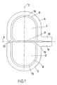
- Fig.1 shows a planar electrode, in particular a neutral electrode for radiofrequency surgery.
- the two areas bordered by solid lines are two electrode surfaces 1, 2 which are electrically separated from one another along a line-shaped insulating zone 8.
- the planar electrode shown in the form of an embodiment can be implemented in any of the known materials for the production of neutral electrodes for single or multiple use.
- the conductive surface may consist of a coated with conductive gel or adhesive metal foil.
- the linear insulating zone 8 is e.g. 2 to 5 mm wide and can be covered either completely free of conductive material, or even with weakly cross-conductive gel or adhesive. Within the scope of the invention it is also possible to use designs which deviate from these specifications as flat electrodes.
- the two electrode surfaces 1, 2 are separated from one another by the line-shaped insulating zone 8, at least partially surrounded by band-shaped extension sections 3, 4 of the respective other electrode surface.
- the two electrode surfaces 1, 2 occupy a central inner region of the electrode according to the invention.
- the band-shaped extension sections 3, 4 are narrow compared to the centrally arranged electrode surfaces 1, 2, i. their length is significantly greater than their width.
- the two electrode surfaces 1, 2 adjoin one another along one inner section 9 of the linear insulating zone 8, and the two electrode surfaces 1, 2 each have a band-shaped extension section 3, 4 which extends around the other electrode surface.
- the strip-shaped extension sections 3, 4 of the two electrode surfaces 1, 2 are guided along the outer sections 15, 16 of the line-shaped insulating zone 8 extending from the inner section 9 about the respective other electrode surface.
- a main axis 7 and a minor axis 6 of the electrode according to the invention are shown.
- the inner portion of the linear insulating zone 8 is rectilinear and extends along a minor axis 6 of the planar electrode.
- the electrode surfaces 1, 2 are formed semicircular. These ends are each surrounded by the extension sections 3, 4 by the outer sections 15, 16 of the linear insulating zone 8 sickle-shaped.
- the electrode according to the invention has an oval shape.
- the invention is not limited to these, it can also be embodied in a different geometric shape. She can be about opposite in Fig.1 illustrated construction arbitrarily compressed or stretched executed, so look from cross-divided over round to longitudinal split.
- the distance of the line-shaped insulating zone 8 can be varied from the edge within wide limits.
- the two electrode surfaces 1, 2 about an axis perpendicular to the plane of the electrode according to the invention, which extends through the intersection of the major and minor axes 7, 6 formed twice-symmetrical.
- the type of symmetry can also be designed differently.
- connecting lugs 10, 11 are arranged at one end of one of the extension sections 3, 4 of the planar electrodes 1, 2 and a transitional area between the other of the planar electrodes 1, 2 and the other extension section 3, 4.
- the terminal lugs 10, 11 extend on one side of the planar electrode in the imaginary extension of the inner portion 9 along the minor axis. 6
- Fig. 1 Shown extend the extension sections 3, 4 each in a lying along the minor axis 6 corner region 13, 14 of the surface electrodes 1, 2 away from the latter, wherein the corner regions 13, 14 with respect to the main axis 7 of the planar electrode are equally spaced.
- the band-shaped extension sections 3, 4 each extend around the other of the two electrode surfaces 1, 2 to substantially in the vicinity of the corner region 13, 14 of this other electrode surface.
- the middle region of the electrode according to the invention absorbs a comparatively small proportion of current and therefore has one lower efficiency than the edge areas.
- space and material-saving terminal lugs 24, 25 are provided in this central region, which are connected to the electrode surfaces 1, 2.
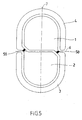
- FIG. Figure 5 . 6 and 7 show further embodiments of the invention, in which the terminal lugs 24, 25 (FIG. Figure 7 ) are arranged centrally.
- the attachment of the terminal lugs is not shown because they are also in a different way than in Fig. 7 shown done, but this does not contribute to the invention.
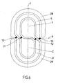
- the electrodes according to Fig. 5 . 6 and 7 are along the course of the band-shaped extension sections 3, 4 interrupted at one or more locations and impedances 50, 51, 52, 53 interposed to form an impedance gradient.
- the arrangement of the impedances can be done, for example, so that the minor axis 6 passes through the attachment points of the impedances 50, 51, 52, 52, whereby a stepwise increase in the impedance to the outside can be realized.
- the current distribution within the electrode according to the invention can be influenced.
- the type, sizing and locations of the impedances 50, 51, 52, 53 can be varied as needed.
- the impedances 50, 51, 52, 53 themselves as well as the electrode surfaces 1, 2 and the extension sections 3, 4 or the outer extension sections 28, 29 can be printed by printing more or less conductive lacquers.
Abstract
Description
Die Erfindung betrifft eine flächige Elektrode, insbesondere Neutralelektrode, für medizinische Zwecke mit zwei gleich großen, entlang einer linienförmigen Isolierzone elektrisch voneinander getrennten Elektrodenflächen, die entlang einem inneren Randteilbereich unmittelbar aneinandergrenzen.The invention relates to a planar electrode, in particular a neutral electrode, for medical purposes with two equally large, along a linear insulating zone electrically separated electrode surfaces which adjoin one another directly along an inner edge portion.
Unter flächigen Elektroden werden im Sinne der Erfindung alle medizinischen Elektroden zur Anbringung auf der Haut verstanden.In the context of the invention, flat electrodes are understood to mean all medical electrodes for attachment to the skin.
In der
Wie aus der
Um das vollflächige Anliegen der Neutralelektrode sicherstellen zu können, sind Überwachungsvorrichtungen entwickelt worden, die während der Operation oder zwischen den einzelnen Behandlungsschritten Widerstands- oder Symmetriemessungen durchführen.In order to ensure the full-surface concerns of the neutral electrode, monitoring devices have been developed that perform resistance or symmetry measurements during the operation or between the individual treatment steps.
So verfügen die im Einsatz befindlichen Hochfrequenzgeneratoren üblicherweise über eine Contact Quality Monitoring-(CQM)-Einrichtung, welche unabhängig vom Schneidestrom der chirurgischen Apparatur die korrekte und vollflächige Applikation der Neutralelektrode auf der Haut des Patienten überprüft. Voraussetzung dafür sind zwei- oder mehrteilige Neutralelektroden, die eine Messung der Impedanz zwischen den Elektrodenteilen ermöglichen. Da der Hautwiderstand von Patient zu Patient stark variiert, ist eine eindeutige Aussage, ob die Neutralelektrode richtig aufliegt oder nicht oft nur sehr schwierig und es kann dabei zu Fehlmessungen kommen.Thus, the high-frequency generators in use usually have a Contact Quality Monitoring (CQM) device, which checks the correct and full-surface application of the neutral electrode on the skin of the patient regardless of the cutting current of the surgical apparatus. Prerequisite for this are two- or multi-part neutral electrodes, which allow a measurement of the impedance between the electrode parts. Since the skin resistance varies greatly from patient to patient, it is a clear statement whether the neutral electrode rests correctly or not often very difficult and it can lead to incorrect measurements.
Durch geeignete Maßnahmen, wie z.B. durch eine möglichst lange linienförmige Isolierzone zwischen den Elektrodenteilen, wie dies in der
Außerdem verfügen einige Hochfrequenzgeneratoren über eine Symmetrieprüfungs-Schaltung, welche über eine Messung des Ableitstromes der Elektrodenteile bestimmt, ob eine symmetrische Stromverteilung vorliegt oder ob ein Elektrodenteil einen höheren Stromanteil führt. Eine solche symmetrische Stromverteilung durch die Neutralelektrode kann mit Hilfe eines geeigneten Designs der Neutralelektrode gefördert werden. Wie sich aber gezeigt hat, reicht es nicht einfach aus, wie bei der Elektrode gemäß
Aufgabe der Erfindung ist es daher, eine eingangs genannte flächige Elektrode anzugeben, mit der über eine CQM-Proportionalisierung hinaus außerdem auch die Erzielung von symmetrischen Ableitströmen im Anwendungsbetrieb erreicht wird. Erfindungsgemäß wird dies dadurch erzielt, daß die zwei gleich großen Elektrodenflächen jeweils einen bandförmigen Verlängerungsabschnitt aufweisen, welcher die jeweils andere Elektrodenfläche zumindest entlang einem äußeren Randteilbereich umgibt und dabei durch die verlängerte Isolierzone von der jeweils umgebenen Elektrodenfläche getrennt ist, und daß die beiden äußeren Randteilbereiche sich im wesentlichen jeweils ausgehend vom einen Ende des inneren Randteilbereiches um die jeweils andere Elektrodenfläche herum zumindest zum gegenüberliegenden anderen Ende des inneren Randteilbereiches erstrecken. Gemäß der Erfindung sind die zwei gleich großen Elektrodenflächen an ihrem dem inneren Teilstück der linienförmigen Isolierzone gegenüberliegenden Ende halbkreisförmig ausgebildet, welches Ende von den bandförmigen Verlängerungsabschnitten durch die äußeren Teilstücke der linienförmigen Isolierzone jeweils sichelförmig umgeben ist.The object of the invention is therefore to provide an aforementioned flat electrode, with the addition of a CQM proportionalization in addition also the achievement of symmetrical leakage currents in the application mode is achieved. According to the invention this is achieved in that the two equal-sized electrode surfaces each have a band-shaped extension portion which surrounds the respective other electrode surface at least along an outer edge portion and is thereby separated by the extended insulating zone of the respectively surrounded electrode surface, and that the two outer edge portions essentially each extending from the one end of the inner edge portion of the respective other electrode surface around at least to the opposite other end of the inner edge portion. According to the invention, the two equal-sized electrode surfaces are semicircular at their opposite end of the inner portion of the line-shaped insulating zone, which end of each of the band-shaped extension portions is surrounded by the outer portions of the line-shaped insulating zone sickle-shaped.
Auf diese Weise kann sowohl ein langer Isolierpfad durch die erfindungsgemäße Elektrode erreicht werden, der eine hohe Empfindlichkeit der CQM-Messung ermöglicht als auch eine Elektrodenflächengestaltung gewählt werden, die eine verläßliche Symmetriemessung der Ableitströme während der Operation gewährleistet, da auch in den Randbereichen, die einen überproportionalen Einfluß auf das Meßergebnis haben, die Anteile der Elektrodenfläche gleich groß angeordnet werden können.In this way, both a long Isolierpfad can be achieved by the electrode according to the invention, which allows high sensitivity of the CQM measurement as well as an electrode surface design can be chosen, which ensures a reliable symmetry measurement of the leakage currents during the operation, as well as in the edge regions disproportionate influence on the measurement result, the proportions of the electrode surface can be arranged the same size.
Die zwei zentral gelegenen Elektrodenflächen sind dabei von den Verlängerungsabschnitten der jeweils anderen Elektrodenfläche umgeben. Ein relativ langer Isolierpfad und auch eine gegenüber den Randbereichen symmetrische Flächenaufteilung der Elektrodenflächen ist dadurch möglich.The two centrally located electrode surfaces are surrounded by the extension sections of the respective other electrode surface. A relatively long insulating path and also a surface area distribution of the electrode surfaces that is symmetrical with respect to the edge regions is thereby possible.
Eine einfache konstruktive Gestaltung ergibt sich, wenn ein inneres Teilstück der linienförmigen Isolierzone und die aneinandergrenzenden inneren Randteilbereiche der zwei gleich großen Elektrodenflächen geradlinig verlaufen und sich entlang einer Nebenachse der flächigen Elektrode erstrecken.A simple structural design results when an inner portion of the line-shaped insulating zone and the adjoining inner edge portions of the two equal-sized electrode surfaces are rectilinear and extend along a minor axis of the planar electrode.
Um die Ausbildung von hohen lokalen Stromdichten während der Anwendung zu verhindern, sind gerundete Elektrodenformen von Vorteil, die kleinere Krümmungsradien in den Randbereichen vermeiden. Für die Anwendung bei Symmetriestrom-Messungen ist eine hohe Flächensymmetrie der Einzeielektroden von Vorteil. In dieser Hinsicht kann ein Merkmal der erfindungsgemäßen Elektrode darin bestehen, daß die zwei Elektrodenflächen um eine Achse senkrecht zur Ebene der flächigen Elektrode zweifach-symmetrisch ausgebildet sind.In order to prevent the formation of high local current densities during application, rounded electrode shapes are advantageous which avoid smaller radii of curvature in the edge regions. For use in symmetry current measurements, a high areal symmetry of the single-electrode electrodes is advantageous. In this regard, a feature of the electrode according to the invention may be that the two electrode surfaces are formed twice symmetrical about an axis perpendicular to the plane of the planar electrode.
Weiters können Anschlußlaschen an einem Ende eines der Verlängerungsabschnitte der Flächenelektroden und einem Übergangsbereich zwischen der anderen der Flächenelektroden und des anderen Verlängerungsabschnittes angeordnet sein. Auf diese Weise kann das Anschließen der erfindungsgemäßen Elektrode an einer Seite erfolgen, wodurch die dieser Seite gegenüberliegende Seite, welche keine Anschlüsse aufweist, dafür geeignet ist, auf dem Patienten in Richtung des Operationsfeldes orientiert zu werden.Further, terminal tabs may be disposed at one end of one of the extension portions of the area electrodes and a transition area between the other of the area electrodes and the other extension portion. In this way, the connection of the electrode according to the invention can take place on one side, whereby the side opposite this side, which has no connections, is suitable for being oriented on the patient in the direction of the surgical field.
Eine vorteilhafte symmetrische Anordnung läßt sich erzielen, wenn die Anschlußlaschen sich an einer Seite der flächigen Elektrode in der gedachten Verlängerung des inneren Teilstückes entlang der Nebenachse erstrecken.An advantageous symmetrical arrangement can be achieved if the terminal lugs extend on one side of the planar electrode in the imaginary extension of the inner portion along the minor axis.
Weiters hat es sich aus mechanischen Gründen und aus Symmetriegründen als günstig erwiesen, wenn die Verlängerungsabschnitte sich jeweils in einem entlang der Nebenachse gelegenen Eckbereich der Flächenelektroden von diesen wegerstrecken, wobei die Eckbereiche gegenüber einer Hauptachse der flächigen Elektrode gleich beabstandet sind, und daß die Verlängerungsabschnitte sich jeweils um die andere der zwei Elektrodenflächen bis im wesentlich in die Nähe des Eckbereiches der anderen Elektrodenfläche erstrecken.Furthermore, it has proved to be favorable for mechanical reasons and for reasons of symmetry, when the extension portions each extend in a lying along the minor axis corner region of the surface electrodes thereof, wherein the corner regions are equally spaced from a major axis of the planar electrode, and in that the extension sections extend around the other of the two electrode surfaces substantially to the vicinity of the corner region of the other electrode surface.
Eine andere Ausführungsform der Erfindung, bei der eine erhöhte Länge der Isolierzone vorliegt, kann darin bestehen, daß sich jeweils entlang der Hauptachse ein Vorsprung der bandförmigen Verlängerungsabschnitte in die jeweils andere Elektrodenfläche erstreckt.Another embodiment of the invention, in which there is an increased length of the insulating zone, may be that each along the major axis a projection of the band-shaped extension portions extends into the respective other electrode surface.
Im zentralen Bereich der erfindungsgemäßen Elektrode ist die Stromdichte während der Anwendung relativ gering, sodaß diese Zone dafür genutzt werden kann, Anschlüsse für die Elektrodenflächen vorzusehen. Dies kann dadurch erreicht werden, daß Anschlußlaschen im mittleren Bereich vorgesehen sind, die mit den Elektrodenflächen verbunden sind.In the central region of the electrode according to the invention, the current density during use is relatively low, so that this zone can be used to provide connections for the electrode surfaces. This can be achieved in that connecting tabs are provided in the central region, which are connected to the electrode surfaces.
Diese Anbringung von Anschlußlaschen im zentralen Bereich einer flächigen Elektrode, insbesondere einer Neutralelektrode kann auch für alle bekannten Ausführungsformen dieses Elektrodentyps angewandt werden und wird als gesonderte Erfindung beansprucht.This attachment of terminal tabs in the central region of a flat electrode, in particular a neutral electrode can also be applied to all known embodiments of this type of electrode and is claimed as a separate invention.
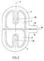
Eine Vervielfachung des erfindungsgemäßen Prinzips, die innerhalb des Schutzumfangs der Erfindung liegt, kann beispielsweise dadurch erzielt werden, daß die um die jeweils andere Elektrodenfläche geführten Verlängerungsabschnitte anschließend in den Bereich der zugehörigen Elektrodenfläche zurückgeführt sind und dort, getrennt durch die linienförmige Isolierzone, die jeweils anderen Verlängerungsabschnitte umgeben.A multiplication of the inventive principle, which is within the scope of the invention, can be achieved, for example, that the guided around the other electrode surface extension sections are then returned to the area of the associated electrode surface and there, separated by the linear insulating zone, the other Surrounding extension sections.
Diesbezüglich sind weitere andere Formen der Führung der Verlängerungsabschnitte im Rahmen der Erfindung ausführbar. So kann vorgesehen sein, daß die bandförmigen Verlängerungsabschnitte um die beiden Elektrodenflächen spiralförmig ineinanderverlaufend zwei oder mehrfach herumgeführt sind.In this regard, other other forms of guiding the extension sections are feasible within the scope of the invention. Thus, it can be provided that the band-shaped extension sections are guided around the two electrode surfaces spirally in one another running two or more times.
Bei mittiger Anordnung der Anschlußlaschen, wenn diese also direkt mit den beiden zentral angeordneten Elektroden verbunden sind, kann es vorteilhaft sein, wenn der Stromanteil des inneren Bereiches gegenüber jenem des äußeren so beeinflußt wird, daß die sonst vorhandene Stromkonzentration in den Randbereichen der Elektrode sich gleichmäßiger über die gesamte Elektrodenfläche verteilt. Dies kann z.B. durch Vorsehen eines von außen nach innen gerichteten Impedanzgradienten erreicht werden. d.h. daß je weiter der Strom in den Außenbereich der Elektrode fließt sich die Impedanz für ihn erhöht.In the central arrangement of the terminal lugs, so if they are directly connected to the two centrally located electrodes, it may be advantageous if the proportion of current of the inner region relative to that of the outer is affected so that the otherwise existing current concentration in the edge regions of the electrode is more uniform distributed over the entire electrode surface. This can be achieved, for example, by providing an externally inward impedance gradient become. that is, the further the current flows into the outer region of the electrode, the impedance for it increases.
Gemäß einer Ausführungsform der Erfindung können zu diesem Zweck entlang des Verlaufes der bandförmigen Verlängerungsabschnitte diese an einer oder mehreren Stellen unterbrochen und Impedanzen zur Ausbildung eines Impedanzgradienten zwischengeschaltet sein.According to one embodiment of the invention, for this purpose along the course of the band-shaped extension sections, these can be interrupted at one or more points and impedances can be interposed to form an impedance gradient.
Nachstehend wird die Erfindung anhand der in den Zeichnungen gezeigten Ausführungsbeispiele eingehend erläutert. Es zeigt dabei
-
Fig.1 eine schematische Draufsicht auf eine Ausführungsform der erfindungsgemäßen Elektrode; -
Fig.2 eine schematische Draufsicht auf eine weitere Ausführungsform der erfindungsgemäßen Elektrode; -
Fig.3 eine schematische Draufsicht auf eine weitere Ausführungsform der erfindungsgemäßen Elektrode; -
Fig.4 eine schematische Draufsicht auf eine weitere Ausführungsform der erfindungsgemäßen Elektrode; -
Fig.5 eine schematische Draufsicht auf eine weitere Ausführungsform der erfindungsgemäßen Elektrode und -
Fig.6 eine schematische Draufsicht auf eine weitere Ausführungsform der erfindungsgemäßen Elektrode.
-
Fig.1 a schematic plan view of an embodiment of the electrode according to the invention; -
Fig.2 a schematic plan view of a further embodiment of the electrode according to the invention; -
Figure 3 a schematic plan view of a further embodiment of the electrode according to the invention; -
Figure 4 a schematic plan view of a further embodiment of the electrode according to the invention; -
Figure 5 a schematic plan view of a further embodiment of the electrode according to the invention and -
Figure 6 a schematic plan view of a further embodiment of the electrode according to the invention.
Die in Form eines Ausführungsbeispiels gezeigte flächige Elektrode kann in jedem der bekannten Materialien zur Herstellung von Neutralelektroden für den einfachen oder mehrfachen Gebrauch umgesetzt werden. Insbesondere kann die leitfähige Fläche aus einer mit leitfähigem Gel oder Kleber beschichteten Metallfolie bestehen. Die linienförmige Isolierzone 8 ist z.B. 2 bis 5 mm breit und kann entweder völlig frei von leitfähigem Material, oder auch mit schwach querleitfähigem Gel oder Kleber überdeckt sein. Es können im Rahmen der Erfindung auch von diesen Angaben abweichende Bauformen als flächige Elektrode angewandt werden.The planar electrode shown in the form of an embodiment can be implemented in any of the known materials for the production of neutral electrodes for single or multiple use. In particular, the conductive surface may consist of a coated with conductive gel or adhesive metal foil. The
Erfindungsgemäß sind die zwei Elektrodenflächen 1, 2 durch die linienförmige Isolierzone 8 voneinander getrennt, zumindest teilweise von bandförmigen Verlängerungsabschnitten 3, 4 der jeweils anderen Elektrodenfläche umschlossen.According to the invention, the two
Gegenüber den bandförmigen Verlängerungsabschnitten 3, 4, die außenliegend angeordnet sind, nehmen die zwei Elektrodenflächen 1, 2 einen zentralen inneren Bereich der erfindungsgemäßen Elektrode ein.Opposite the band-
Die bandförmigen Verlängerungsabschnitte 3, 4 sind im Vergleich zu den zentral angeordneten Elektrodenflächen 1, 2 schmal ausgebildet, d.h. ihre Länge ist deutlich größer als ihre Breite.The band-
Im inneren Bereich grenzen die zwei Elektrodenflächen 1, 2 an einer Seite entlang einem inneren Teilstück 9 der linienförmigen Isolierzone 8 aneinander, und die zwei Elektrodenflächen 1, 2 weisen jeweils einen bandförmigen Verlängerungsabschnitt 3, 4 auf, der sich jeweils um die andere Elektrodenfläche erstreckt.In the inner region, the two
Die bandförmigen Verlängerungsabschnitte 3, 4 der zwei Elektrodenflächen 1, 2 sind entlang der vom inneren Teilstück 9 ausgehenden äußeren Teilstücke 15, 16 der linienförmigen Isolierzone 8 um die jeweils andere Elektrodenfläche geführt.The strip-shaped
Für weitere geometrische Überlegungen ist in
Das innere Teilstück der linienförmigen Isolierzone 8 verläuft geradlinig und erstreckt sich entlang einer Nebenachse 6 der flächigen Elektrode.The inner portion of the linear insulating
An ihrem dem inneren Teilstück 9 gegenüberliegenden Ende sind die Elektrodenflächen 1, 2 halbkreisförmig ausgebildet. Diese Enden sind von den Verlängerungsabschnitten 3, 4 durch die äußeren Teilstücke 15, 16 der linienförmigen Isolierzone 8 jeweils sichelförmig umgeben.At its opposite end of the
In dem in
Im wesentlichen sind die zwei Elektrodenflächen 1, 2 um eine Achse senkrecht zur Ebene der erfindungsgemäßen Elektrode, die durch den Schnittpunkt von Haupt- und Nebenachse 7, 6 verläuft zweifach-symmetrisch ausgebildet. Die Art der Symmetrie kann auch anders gestaltet sein.In essence, the two
Zur Abführung des Ableitstromes bzw. zur Einprägung eines Meßstromes sind Anschlußlaschen 10, 11 an einem Ende eines der Verlängerungsabschnitte 3, 4 der Flächenelektroden 1, 2 und einem Übergangsbereich zwischen der anderen der Flächenelektroden 1, 2 und des anderen Verlängerungsabschnittes 3, 4 angeordnet. Die Anschlußlaschen 10, 11 erstrecken sich dabei an einer Seite der flächigen Elektrode in der gedachten Verlängerung des inneren Teilstückes 9 entlang der Nebenachse 6.For discharging the leakage current or for impressing a measuring current, connecting
Wie weiters in
Bei der in
Der mittlere Bereich der erfindungsgemäßen Elektrode nimmt aufgrund des Randeffektes einen vergleichsweise geringen Stromanteil auf und weist daher einen geringeren Wirkungsgrad auf als die Randbereiche. In der in
Schließlich sind in der in
In den Elektroden gemäß
Die Impedanzen 50, 51, 52, 53 selbst können sowie die Elektrodenflächen 1, 2 und die Verlängerungsabschnitte 3, 4 bzw. die außenliegenden Verlängerungsabschnitte 28, 29 durch Aufdrucken von mehr oder weniger leitfähigen Lacken aufgedruckt werden.The
Claims (12)
- A planar electrode, in particular a neutral electrode, for medical purposes comprising two equal electrode surfaces (1, 2), electrically separated along a linear insulation zone (8), which adjoins directly along an inner edge portion,
wherein said two equal electrode surfaces (1, 2) comprise, respectively, a band-shaped extension section (3, 4), which encloses said other electrode surface (1, 2) at least along an outer edge portion (15, 16) and thereby is separated by said extended insulation zone (8) from said respectively enclosed electrode surface (1, 2),
wherein said two outer edge portions (15, 16) extend substantially, respectively, going out from one end of said inner edge portion (9) around the other electrode surface (1, 2) at least to the opposite other end of said inner edge portion (9),
wherein said two equal electrode surfaces (1, 2) at their end opposite to said inner part (9) of said linear insulation zone (8) are formed semicircular, which end of said band-shaped extension sections (3, 4) is enclosed by the outer parts (15, 16) of said linear insulation zone (8), respectively, in sickle-shaped manner. - The planar electrode according to claim 1,
characterized in that
an inner part (9) of said linear insulation zone (8) and said adjoining inner edge portions of said two equal electrode surfaces (1, 2) run straight and extend along a minor axis (6) of said planar electrode. - The planar electrode according to claim 1 or 2,
characterized in that
said two electrode surfaces (1, 2) are formed double symmetric around an axis perpendicular to the plane of said planar electrode. - The planar electrode according to one of the preceding claims 1 to 3,
characterized in that
terminal lugs (10, 11) are arranged at one end of one of said extension sections (3, 4) of said planar electrodes (1, 2) and a transition region between the other one of said planar electrodes (1, 2) and of said other extension section (3, 4). - The planar electrode according to claim 4,
characterized in that
said terminal lugs (10, 11) extend at one side of said planar electrode in the imaginary extension of said inner part (9) along said minor axis (6). - The planar electrode according to one of the preceding claims,
characterized in that
said extension sections (3, 4), respectively, in a corner region (13, 14) situated along said minor axis (6) of said planar electrodes (1, 2) extend away from these, wherein the corner regions (13, 14) opposite a main axis (7) of said planar electrode are equally spaced, and that said extension sections (3, 4) extend, respectively, around the other one of said two electrode surfaces (1, 2) until substantially in the vicinity of the corner region (13, 14) of the other electrode surface. - The planar electrode according to one of the preceding claims,
characterized in that
a protrusion (20, 21) of said band-shaped extension sections (3, 4) extends, respectively, along said main axis (7) in the respective other electrode surface (1, 2). - The planar electrode, in particular according to one of the claims 1 to 3,
characterized in that
terminal lugs (24, 25) are provided in the middle region, which are connected with said electrode surfaces (1, 2). - The planar electrode according to claim 1,
characterized in that
said extension sections (3, 4) guided around said respective other electrode surface (1, 2) subsequently are guided back in the region of the associated electrode surface (1, 2) and there, separated by said linear insulation zone (8), enclose the respective other extension sections (3, 4). - The planar electrode according to claim 1,
characterized in that
said band-shaped extension sections (3, 4) are guided around said two electrode surfaces (1, 2) intertwining in spiral form two or several times. - The planar electrode according to one of the preceding clams,
characterized in that
along the course of said band-shaped extension sections (3, 4) these are interrupted at one or at a plurality of positions and impedances (50, 51, 52, 53) are interposed for forming an impedance gradient. - The planar electrode according to claim 11,
characterized in that
said minor axis (6) extends through said attachment positions of said impedances (50, 51, 52, 53).
Priority Applications (2)
| Application Number | Priority Date | Filing Date | Title |
|---|---|---|---|
| PL06704699T PL2007302T3 (en) | 2005-02-23 | 2006-02-16 | Planar electrode |
| EP10158696.4A EP2208476B1 (en) | 2005-02-23 | 2006-02-16 | Flat electrode |
Applications Claiming Priority (2)
| Application Number | Priority Date | Filing Date | Title |
|---|---|---|---|
| AT0030605A AT503078B1 (en) | 2005-02-23 | 2005-02-23 | FLAT ELECTRODE |
| PCT/AT2006/000057 WO2006089319A1 (en) | 2005-02-23 | 2006-02-16 | Planar electrode |
Related Child Applications (2)
| Application Number | Title | Priority Date | Filing Date |
|---|---|---|---|
| EP10158696.4A Division EP2208476B1 (en) | 2005-02-23 | 2006-02-16 | Flat electrode |
| EP10158696.4 Division-Into | 2010-03-31 |
Publications (3)
| Publication Number | Publication Date |
|---|---|
| EP2007302A1 EP2007302A1 (en) | 2008-12-31 |
| EP2007302B1 true EP2007302B1 (en) | 2010-07-14 |
| EP2007302B9 EP2007302B9 (en) | 2010-11-03 |
Family
ID=36208793
Family Applications (2)
| Application Number | Title | Priority Date | Filing Date |
|---|---|---|---|
| EP06704699A Active EP2007302B9 (en) | 2005-02-23 | 2006-02-16 | Planar electrode |
| EP10158696.4A Active EP2208476B1 (en) | 2005-02-23 | 2006-02-16 | Flat electrode |
Family Applications After (1)
| Application Number | Title | Priority Date | Filing Date |
|---|---|---|---|
| EP10158696.4A Active EP2208476B1 (en) | 2005-02-23 | 2006-02-16 | Flat electrode |
Country Status (9)
| Country | Link |
|---|---|
| US (1) | US8986295B2 (en) |
| EP (2) | EP2007302B9 (en) |
| AT (2) | AT503078B1 (en) |
| DE (1) | DE502006007458D1 (en) |
| DK (1) | DK2007302T3 (en) |
| ES (1) | ES2351248T3 (en) |
| HK (1) | HK1126642A1 (en) |
| PL (2) | PL2208476T3 (en) |
| WO (1) | WO2006089319A1 (en) |
Families Citing this family (5)
| Publication number | Priority date | Publication date | Assignee | Title |
|---|---|---|---|---|
| DE102012010262B4 (en) | 2012-05-25 | 2014-07-03 | Albrecht Molsberger | Therapeutically applicable DC delivery device |
| WO2019109334A1 (en) * | 2017-12-08 | 2019-06-13 | 赛诺微医疗科技(浙江)有限公司 | Apparatus and method for measuring contact quality of negative plate of high-frequency electrotome |
| CN107907744B (en) * | 2017-12-08 | 2020-10-23 | 赛诺微医疗科技(浙江)有限公司 | Device and method for measuring contact quality of negative plate of high-frequency electrotome |
| EP4186558A1 (en) * | 2021-11-25 | 2023-05-31 | Fundación Tecnalia Research & Innovation | Electrical stimulation electrodes and electrical stimulation of a person |
| CN114209418B (en) * | 2021-12-13 | 2023-08-08 | 宝施医疗用品(深圳)有限公司 | Neutral electrode for inductive homogenization current |
Family Cites Families (6)
| Publication number | Priority date | Publication date | Assignee | Title |
|---|---|---|---|---|
| CA1219642A (en) * | 1984-04-18 | 1987-03-24 | Monique Frize | Multi-element electrosurgical indifferent electrode with temperature balancing resistors |
| EP0416159B1 (en) * | 1989-09-07 | 1995-05-24 | Siemens Aktiengesellschaft | Adhesive electrode pad for a HF surgical apparatus |
| EP0463196A1 (en) * | 1990-06-23 | 1992-01-02 | Erbe Elektromedizin GmbH | Passive electrode for high frequency surgery |
| DE4231236C2 (en) * | 1992-09-18 | 1995-08-31 | Aesculap Ag | Flat electrode for high-frequency surgery |
| AT407486B (en) * | 1999-04-29 | 2001-03-26 | Leonhard Lang Kg | MEDICAL ELECTRODE |
| US7771419B2 (en) * | 2004-10-05 | 2010-08-10 | Granite Advisory Services, Inc. | Biomedical dispersive electrode |
-
2005
- 2005-02-23 AT AT0030605A patent/AT503078B1/en active
-
2006
- 2006-02-16 PL PL10158696T patent/PL2208476T3/en unknown
- 2006-02-16 US US12/515,042 patent/US8986295B2/en active Active
- 2006-02-16 EP EP06704699A patent/EP2007302B9/en active Active
- 2006-02-16 WO PCT/AT2006/000057 patent/WO2006089319A1/en active Application Filing
- 2006-02-16 ES ES06704699T patent/ES2351248T3/en active Active
- 2006-02-16 DE DE502006007458T patent/DE502006007458D1/en active Active
- 2006-02-16 PL PL06704699T patent/PL2007302T3/en unknown
- 2006-02-16 DK DK06704699.5T patent/DK2007302T3/en active
- 2006-02-16 EP EP10158696.4A patent/EP2208476B1/en active Active
- 2006-02-16 AT AT06704699T patent/ATE473703T1/en active
-
2009
- 2009-06-24 HK HK09105678.9A patent/HK1126642A1/en not_active IP Right Cessation
Also Published As
| Publication number | Publication date |
|---|---|
| DE502006007458D1 (en) | 2010-08-26 |
| EP2007302B9 (en) | 2010-11-03 |
| US20100036377A1 (en) | 2010-02-11 |
| ATE473703T1 (en) | 2010-07-15 |
| AT503078A1 (en) | 2007-07-15 |
| EP2208476A1 (en) | 2010-07-21 |
| AT503078B1 (en) | 2010-10-15 |
| EP2007302A1 (en) | 2008-12-31 |
| DK2007302T3 (en) | 2010-11-15 |
| EP2208476A9 (en) | 2010-10-27 |
| US8986295B2 (en) | 2015-03-24 |
| HK1126642A1 (en) | 2009-09-11 |
| EP2208476B1 (en) | 2016-07-20 |
| WO2006089319A1 (en) | 2006-08-31 |
| ES2351248T3 (en) | 2011-02-02 |
| PL2007302T3 (en) | 2011-03-31 |
| PL2208476T3 (en) | 2017-07-31 |
Similar Documents
| Publication | Publication Date | Title |
|---|---|---|
| DE3916161C2 (en) | ||
| EP2842506B1 (en) | Medical instrument and electro-surgical system | |
| DE3623293C2 (en) | Multi-part flat electrode, especially for HF surgery | |
| EP0416159A1 (en) | Adhesive electrode pad for a HF surgical apparatus | |
| EP2007302B9 (en) | Planar electrode | |
| DE3206947A1 (en) | Neutral electrode for radio-frequency surgery | |
| DE102006006052A1 (en) | High frequency treatment device for an endoscope | |
| DE102013001156A1 (en) | Bipolar resectoscope | |
| DE112012002861T5 (en) | Shunt resistor and method of making same | |
| WO2010128150A1 (en) | Medical instrument | |
| EP1163885B1 (en) | Endoscopic instrument with two electrodes | |
| EP2653123B1 (en) | Tool for a medical instrument | |
| EP3477784B1 (en) | Handle for a microinvasive medical instrument | |
| DE102007042524A1 (en) | Coagulation template and application device | |
| EP0308690A1 (en) | Electrosurgical indifferent electrode provided with at least three sections | |
| EP3416577B1 (en) | Surgical device multi-socket, electro-surgical high-frequency generator and electro-surgical system | |
| DE102015108078A1 (en) | Electrosurgical coagulation instrument | |
| DE102006049716A1 (en) | Magnetic pole for magnetic levitation vehicles | |
| DE19526243C1 (en) | Electrode for vaporizing tissue | |
| DE1039148B (en) | Electrode for generating a high-frequency magnetic vortex field | |
| EP3791782B1 (en) | Catheter with flexible circuit board and method of manufacturing flexible circuit board | |
| DE3518245A1 (en) | Electrical coaxial cable having an integrated heating element | |
| EP3957231A1 (en) | Flexible circuit board and catheter with such a circuit board | |
| DE202023106679U1 (en) | Head of a physiotherapy machine and physiotherapy machine | |
| EP3406218A1 (en) | Coagulation and desection instrument with pin electrodes |
Legal Events
| Date | Code | Title | Description |
|---|---|---|---|
| PUAI | Public reference made under article 153(3) epc to a published international application that has entered the european phase |
Free format text: ORIGINAL CODE: 0009012 |
|
| 17P | Request for examination filed |
Effective date: 20070820 |
|
| AK | Designated contracting states |
Kind code of ref document: A1 Designated state(s): AT BE BG CH CY CZ DE DK EE ES FI FR GB GR HU IE IS IT LI LT LU LV MC NL PL PT RO SE SI SK TR |
|
| AX | Request for extension of the european patent |
Extension state: AL BA HR MK YU |
|
| 17Q | First examination report despatched |
Effective date: 20081223 |
|
| REG | Reference to a national code |
Ref country code: HK Ref legal event code: DE Ref document number: 1126642 Country of ref document: HK |
|
| GRAP | Despatch of communication of intention to grant a patent |
Free format text: ORIGINAL CODE: EPIDOSNIGR1 |
|
| GRAS | Grant fee paid |
Free format text: ORIGINAL CODE: EPIDOSNIGR3 |
|
| GRAA | (expected) grant |
Free format text: ORIGINAL CODE: 0009210 |
|
| AK | Designated contracting states |
Kind code of ref document: B1 Designated state(s): AT BE BG CH CY CZ DE DK EE ES FI FR GB GR HU IE IS IT LI LT LU LV MC NL PL PT RO SE SI SK TR |
|
| AX | Request for extension of the european patent |
Extension state: AL BA HR MK YU |
|
| REG | Reference to a national code |
Ref country code: GB Ref legal event code: FG4D Free format text: NOT ENGLISH |
|
| REG | Reference to a national code |
Ref country code: CH Ref legal event code: EP |
|
| REG | Reference to a national code |
Ref country code: IE Ref legal event code: FG4D |
|
| REF | Corresponds to: |
Ref document number: 502006007458 Country of ref document: DE Date of ref document: 20100826 Kind code of ref document: P |
|
| REG | Reference to a national code |
Ref country code: NL Ref legal event code: VDEP Effective date: 20100714 |
|
| REG | Reference to a national code |
Ref country code: DK Ref legal event code: T3 |
|
| REG | Reference to a national code |
Ref country code: GR Ref legal event code: EP Ref document number: 20100402390 Country of ref document: GR |
|
| LTIE | Lt: invalidation of european patent or patent extension |
Effective date: 20100714 |
|
| PG25 | Lapsed in a contracting state [announced via postgrant information from national office to epo] |
Ref country code: NL Free format text: LAPSE BECAUSE OF FAILURE TO SUBMIT A TRANSLATION OF THE DESCRIPTION OR TO PAY THE FEE WITHIN THE PRESCRIBED TIME-LIMIT Effective date: 20100714 Ref country code: FI Free format text: LAPSE BECAUSE OF FAILURE TO SUBMIT A TRANSLATION OF THE DESCRIPTION OR TO PAY THE FEE WITHIN THE PRESCRIBED TIME-LIMIT Effective date: 20100714 Ref country code: LT Free format text: LAPSE BECAUSE OF FAILURE TO SUBMIT A TRANSLATION OF THE DESCRIPTION OR TO PAY THE FEE WITHIN THE PRESCRIBED TIME-LIMIT Effective date: 20100714 |
|
| REG | Reference to a national code |
Ref country code: ES Ref legal event code: FG2A Effective date: 20110121 |
|
| REG | Reference to a national code |
Ref country code: IE Ref legal event code: FD4D |
|
| PG25 | Lapsed in a contracting state [announced via postgrant information from national office to epo] |
Ref country code: SI Free format text: LAPSE BECAUSE OF FAILURE TO SUBMIT A TRANSLATION OF THE DESCRIPTION OR TO PAY THE FEE WITHIN THE PRESCRIBED TIME-LIMIT Effective date: 20100714 Ref country code: PT Free format text: LAPSE BECAUSE OF FAILURE TO SUBMIT A TRANSLATION OF THE DESCRIPTION OR TO PAY THE FEE WITHIN THE PRESCRIBED TIME-LIMIT Effective date: 20101115 Ref country code: IS Free format text: LAPSE BECAUSE OF FAILURE TO SUBMIT A TRANSLATION OF THE DESCRIPTION OR TO PAY THE FEE WITHIN THE PRESCRIBED TIME-LIMIT Effective date: 20101114 Ref country code: CY Free format text: LAPSE BECAUSE OF FAILURE TO SUBMIT A TRANSLATION OF THE DESCRIPTION OR TO PAY THE FEE WITHIN THE PRESCRIBED TIME-LIMIT Effective date: 20100714 Ref country code: BG Free format text: LAPSE BECAUSE OF FAILURE TO SUBMIT A TRANSLATION OF THE DESCRIPTION OR TO PAY THE FEE WITHIN THE PRESCRIBED TIME-LIMIT Effective date: 20101014 |
|
| REG | Reference to a national code |
Ref country code: HK Ref legal event code: GR Ref document number: 1126642 Country of ref document: HK |
|
| PG25 | Lapsed in a contracting state [announced via postgrant information from national office to epo] |
Ref country code: LV Free format text: LAPSE BECAUSE OF FAILURE TO SUBMIT A TRANSLATION OF THE DESCRIPTION OR TO PAY THE FEE WITHIN THE PRESCRIBED TIME-LIMIT Effective date: 20100714 Ref country code: SE Free format text: LAPSE BECAUSE OF FAILURE TO SUBMIT A TRANSLATION OF THE DESCRIPTION OR TO PAY THE FEE WITHIN THE PRESCRIBED TIME-LIMIT Effective date: 20100714 |
|
| REG | Reference to a national code |
Ref country code: PL Ref legal event code: T3 |
|
| PG25 | Lapsed in a contracting state [announced via postgrant information from national office to epo] |
Ref country code: IE Free format text: LAPSE BECAUSE OF FAILURE TO SUBMIT A TRANSLATION OF THE DESCRIPTION OR TO PAY THE FEE WITHIN THE PRESCRIBED TIME-LIMIT Effective date: 20100714 |
|
| PLBE | No opposition filed within time limit |
Free format text: ORIGINAL CODE: 0009261 |
|
| STAA | Information on the status of an ep patent application or granted ep patent |
Free format text: STATUS: NO OPPOSITION FILED WITHIN TIME LIMIT |
|
| PG25 | Lapsed in a contracting state [announced via postgrant information from national office to epo] |
Ref country code: CZ Free format text: LAPSE BECAUSE OF FAILURE TO SUBMIT A TRANSLATION OF THE DESCRIPTION OR TO PAY THE FEE WITHIN THE PRESCRIBED TIME-LIMIT Effective date: 20100714 Ref country code: EE Free format text: LAPSE BECAUSE OF FAILURE TO SUBMIT A TRANSLATION OF THE DESCRIPTION OR TO PAY THE FEE WITHIN THE PRESCRIBED TIME-LIMIT Effective date: 20100714 Ref country code: SK Free format text: LAPSE BECAUSE OF FAILURE TO SUBMIT A TRANSLATION OF THE DESCRIPTION OR TO PAY THE FEE WITHIN THE PRESCRIBED TIME-LIMIT Effective date: 20100714 Ref country code: RO Free format text: LAPSE BECAUSE OF FAILURE TO SUBMIT A TRANSLATION OF THE DESCRIPTION OR TO PAY THE FEE WITHIN THE PRESCRIBED TIME-LIMIT Effective date: 20100714 |
|
| 26N | No opposition filed |
Effective date: 20110415 |
|
| REG | Reference to a national code |
Ref country code: DE Ref legal event code: R097 Ref document number: 502006007458 Country of ref document: DE Effective date: 20110415 |
|
| BERE | Be: lapsed |
Owner name: NESSLER MEDIZINTECHNIK GMBH Effective date: 20110228 |
|
| PG25 | Lapsed in a contracting state [announced via postgrant information from national office to epo] |
Ref country code: MC Free format text: LAPSE BECAUSE OF NON-PAYMENT OF DUE FEES Effective date: 20110228 |
|
| REG | Reference to a national code |
Ref country code: CH Ref legal event code: PL |
|
| PG25 | Lapsed in a contracting state [announced via postgrant information from national office to epo] |
Ref country code: CH Free format text: LAPSE BECAUSE OF NON-PAYMENT OF DUE FEES Effective date: 20110228 Ref country code: LI Free format text: LAPSE BECAUSE OF NON-PAYMENT OF DUE FEES Effective date: 20110228 |
|
| PG25 | Lapsed in a contracting state [announced via postgrant information from national office to epo] |
Ref country code: BE Free format text: LAPSE BECAUSE OF NON-PAYMENT OF DUE FEES Effective date: 20110228 |
|
| REG | Reference to a national code |
Ref country code: CH Ref legal event code: NV Representative=s name: RIEDERER HASLER & PARTNER PATENTANWAELTE AG Ref country code: CH Ref legal event code: AEN Free format text: DAS PATENT IST AUFGRUND DES WEITERBEHANDLUNGSANTRAGS VOM 25.10.2011 REAKTIVIERT WORDEN. |
|
| PGRI | Patent reinstated in contracting state [announced from national office to epo] |
Ref country code: CH Effective date: 20111122 |
|
| PG25 | Lapsed in a contracting state [announced via postgrant information from national office to epo] |
Ref country code: LU Free format text: LAPSE BECAUSE OF NON-PAYMENT OF DUE FEES Effective date: 20110216 |
|
| PG25 | Lapsed in a contracting state [announced via postgrant information from national office to epo] |
Ref country code: HU Free format text: LAPSE BECAUSE OF FAILURE TO SUBMIT A TRANSLATION OF THE DESCRIPTION OR TO PAY THE FEE WITHIN THE PRESCRIBED TIME-LIMIT Effective date: 20100714 |
|
| REG | Reference to a national code |
Ref country code: FR Ref legal event code: PLFP Year of fee payment: 11 |
|
| PGFP | Annual fee paid to national office [announced via postgrant information from national office to epo] |
Ref country code: ES Payment date: 20160223 Year of fee payment: 11 Ref country code: DK Payment date: 20160222 Year of fee payment: 11 Ref country code: IT Payment date: 20160223 Year of fee payment: 11 Ref country code: CH Payment date: 20160301 Year of fee payment: 11 Ref country code: TR Payment date: 20160211 Year of fee payment: 11 |
|
| PGFP | Annual fee paid to national office [announced via postgrant information from national office to epo] |
Ref country code: GR Payment date: 20160323 Year of fee payment: 11 |
|
| REG | Reference to a national code |
Ref country code: FR Ref legal event code: PLFP Year of fee payment: 12 |
|
| PGFP | Annual fee paid to national office [announced via postgrant information from national office to epo] |
Ref country code: AT Payment date: 20170228 Year of fee payment: 12 |
|
| REG | Reference to a national code |
Ref country code: DK Ref legal event code: EBP Effective date: 20170228 |
|
| REG | Reference to a national code |
Ref country code: CH Ref legal event code: PL |
|
| PG25 | Lapsed in a contracting state [announced via postgrant information from national office to epo] |
Ref country code: CH Free format text: LAPSE BECAUSE OF NON-PAYMENT OF DUE FEES Effective date: 20170228 Ref country code: GR Free format text: LAPSE BECAUSE OF NON-PAYMENT OF DUE FEES Effective date: 20170906 Ref country code: LI Free format text: LAPSE BECAUSE OF NON-PAYMENT OF DUE FEES Effective date: 20170228 |
|
| PG25 | Lapsed in a contracting state [announced via postgrant information from national office to epo] |
Ref country code: DK Free format text: LAPSE BECAUSE OF NON-PAYMENT OF DUE FEES Effective date: 20170228 |
|
| REG | Reference to a national code |
Ref country code: FR Ref legal event code: PLFP Year of fee payment: 13 |
|
| PG25 | Lapsed in a contracting state [announced via postgrant information from national office to epo] |
Ref country code: IT Free format text: LAPSE BECAUSE OF NON-PAYMENT OF DUE FEES Effective date: 20170216 |
|
| REG | Reference to a national code |
Ref country code: ES Ref legal event code: FD2A Effective date: 20180704 |
|
| PG25 | Lapsed in a contracting state [announced via postgrant information from national office to epo] |
Ref country code: ES Free format text: LAPSE BECAUSE OF NON-PAYMENT OF DUE FEES Effective date: 20170217 |
|
| REG | Reference to a national code |
Ref country code: AT Ref legal event code: MM01 Ref document number: 473703 Country of ref document: AT Kind code of ref document: T Effective date: 20180216 |
|
| PG25 | Lapsed in a contracting state [announced via postgrant information from national office to epo] |
Ref country code: AT Free format text: LAPSE BECAUSE OF NON-PAYMENT OF DUE FEES Effective date: 20180216 |
|
| PG25 | Lapsed in a contracting state [announced via postgrant information from national office to epo] |
Ref country code: TR Free format text: LAPSE BECAUSE OF NON-PAYMENT OF DUE FEES Effective date: 20170216 |
|
| PGFP | Annual fee paid to national office [announced via postgrant information from national office to epo] |
Ref country code: FR Payment date: 20230222 Year of fee payment: 18 |
|
| PGFP | Annual fee paid to national office [announced via postgrant information from national office to epo] |
Ref country code: PL Payment date: 20230131 Year of fee payment: 18 Ref country code: GB Payment date: 20230131 Year of fee payment: 18 Ref country code: DE Payment date: 20230127 Year of fee payment: 18 |