EP2007269B1 - Steering system tension control devices - Google Patents
Steering system tension control devices Download PDFInfo
- Publication number
- EP2007269B1 EP2007269B1 EP07757655.1A EP07757655A EP2007269B1 EP 2007269 B1 EP2007269 B1 EP 2007269B1 EP 07757655 A EP07757655 A EP 07757655A EP 2007269 B1 EP2007269 B1 EP 2007269B1
- Authority
- EP
- European Patent Office
- Prior art keywords
- spring
- block
- tension
- control cable
- outer sheath
- Prior art date
- Legal status (The legal status is an assumption and is not a legal conclusion. Google has not performed a legal analysis and makes no representation as to the accuracy of the status listed.)
- Active
Links
Images


Classifications
-
- A—HUMAN NECESSITIES
- A61—MEDICAL OR VETERINARY SCIENCE; HYGIENE
- A61B—DIAGNOSIS; SURGERY; IDENTIFICATION
- A61B1/00—Instruments for performing medical examinations of the interior of cavities or tubes of the body by visual or photographical inspection, e.g. endoscopes; Illuminating arrangements therefor
- A61B1/005—Flexible endoscopes
- A61B1/0051—Flexible endoscopes with controlled bending of insertion part
- A61B1/0052—Constructional details of control elements, e.g. handles
-
- A—HUMAN NECESSITIES
- A61—MEDICAL OR VETERINARY SCIENCE; HYGIENE
- A61B—DIAGNOSIS; SURGERY; IDENTIFICATION
- A61B1/00—Instruments for performing medical examinations of the interior of cavities or tubes of the body by visual or photographical inspection, e.g. endoscopes; Illuminating arrangements therefor
- A61B1/005—Flexible endoscopes
-
- A—HUMAN NECESSITIES
- A61—MEDICAL OR VETERINARY SCIENCE; HYGIENE
- A61B—DIAGNOSIS; SURGERY; IDENTIFICATION
- A61B1/00—Instruments for performing medical examinations of the interior of cavities or tubes of the body by visual or photographical inspection, e.g. endoscopes; Illuminating arrangements therefor
- A61B1/005—Flexible endoscopes
- A61B1/0051—Flexible endoscopes with controlled bending of insertion part
-
- A—HUMAN NECESSITIES
- A61—MEDICAL OR VETERINARY SCIENCE; HYGIENE
- A61B—DIAGNOSIS; SURGERY; IDENTIFICATION
- A61B1/00—Instruments for performing medical examinations of the interior of cavities or tubes of the body by visual or photographical inspection, e.g. endoscopes; Illuminating arrangements therefor
- A61B1/005—Flexible endoscopes
- A61B1/0051—Flexible endoscopes with controlled bending of insertion part
- A61B1/0057—Constructional details of force transmission elements, e.g. control wires
-
- A—HUMAN NECESSITIES
- A61—MEDICAL OR VETERINARY SCIENCE; HYGIENE
- A61B—DIAGNOSIS; SURGERY; IDENTIFICATION
- A61B1/00—Instruments for performing medical examinations of the interior of cavities or tubes of the body by visual or photographical inspection, e.g. endoscopes; Illuminating arrangements therefor
- A61B1/005—Flexible endoscopes
- A61B1/0051—Flexible endoscopes with controlled bending of insertion part
- A61B1/0052—Constructional details of control elements, e.g. handles
- A61B1/0053—Constructional details of control elements, e.g. handles using distributed actuators, e.g. artificial muscles
-
- A—HUMAN NECESSITIES
- A61—MEDICAL OR VETERINARY SCIENCE; HYGIENE
- A61B—DIAGNOSIS; SURGERY; IDENTIFICATION
- A61B1/00—Instruments for performing medical examinations of the interior of cavities or tubes of the body by visual or photographical inspection, e.g. endoscopes; Illuminating arrangements therefor
- A61B1/005—Flexible endoscopes
- A61B1/0051—Flexible endoscopes with controlled bending of insertion part
- A61B1/0055—Constructional details of insertion parts, e.g. vertebral elements
- A61B1/0056—Constructional details of insertion parts, e.g. vertebral elements the insertion parts being asymmetric, e.g. for unilateral bending mechanisms
Definitions
- the present invention relates to medical instruments in general, and to instruments with steerable shafts in particular.
- endoscopes and catheters As an alternative to performing more invasive medical procedures, many physicians are utilizing endoscopes and catheters to perform diagnostic and therapeutic procedures on the internal tissues of patients. With this less invasive approach, a medical instrument, such as an endoscope or a catheter is advanced to a site of interest in order to perform the indicated procedure.
- Most endoscopes and catheters have a flexible shaft that allows the endoscope or catheter to wind its way through bends in the patient's anatomy until it reaches the tissue of interest.
- most steerable endoscopes In order to advance the flexible shaft, most steerable endoscopes have a system of control cables that act in pairs to help direct the distal tip of the shaft. Each control cable is disposed opposite to its pair, and the control cables move in opposition to one another such that as one control cable is being pulled, the other is being released.
- the control cables have an outer sheath and an inner core wire.
- the outer sheath acts to transmit the longitudinal motion of the core wire to the distal tip of the endoscope.
- the shaft During a medical procedure, it is not uncommon for the shaft to form one or more loops as it is navigated to the tissue of interest.
- the outer sheath becomes increasingly stiff and harder to navigate within the body.
- the distances traveled by the core wire and its respective outer sheath differ, producing tension in the outer sheath and/or the core wire and increasing the amount of force needed to exert longitudinal force in the pull wire. This results in the user having less control over the tip of the device and less ability to detect external forces acting on the tip. Therefore, there is a need for a navigation system for use in steerable medical instruments that is still steerable at low forces if looped in the body.
- EP 0 165 718 A discloses an endoscope having an insertion tube constructed from a plurality of disks strung together on steering cables and received in a flexible plastics sheath. Each disk is formed with a plurality of service apertures defining a plurality of service passages of equal diameter within the chain of disks. The cable apertures in the disks are skewed so that each cable follows a helical path along the length of the insertion tube.
- US 4 762 118 A discloses a self-adjusting steering mechanism for a borescope, endoscope, or guide tube.
- US 2004/0186350 A1 discloses an apparatus for guiding an endoscope during an endoluminal procedure via one or rigidizable wires.
- US 5 448 989 A discloses a shaft for medical instruments, especially for guiding instruments into body cavities, which has neighboring segments that are hollow on the inside and that form sections of the shaft.
- the segments can be adjusted in their positions by means of control wires so that various shaft curvatures can be set, whereby at least two groups of segments can be adjusted independently of one another.
- WO 93/20742 A discloses an endoscope for direct visualization of the spine.
- a steerable medical instrument as recited in independent claim 1 is provided.
- the dependent claims define embodiments.
- the present invention is an elongated medical instrument including a shaft that is steerable in a desired direction.
- Control cables in the shaft include an outer sheath and an inner core wire that is tensioned to articulate the distal tip of the shaft.
- the ends of the control cable are in contact with a steering system tension control device so that tension in the control cable created as a result of loops or bends in the shaft is relieved.
- the present invention is a device for relieving tension that occurs in control cables of steerable medical instruments as a result of loops and bends in the instrument.
- the disclosed embodiments are shown for use in an endoscope, it will be appreciated that the invention may be used in any steerable medical instrument, such as catheters for vascular, urological, and laparoscopic applications or the like.
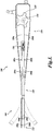
- FIGURE 1 illustrates an endoscope 100 including a steering system tension control device 120 made in accordance with one embodiment of the present invention. Not all of the features of the endoscope 100 are being illustrated for brevity.
- the endoscope 100 includes a handle 116 that is connected to a shaft 108 having a proximal end 110 and a distal end 112.
- the handle 116 is connected to the proximal end 110 of the shaft 108.
- a pair of control cables 102a and 102b is used to steer the distal end 112 of the shaft 108.
- the control cables 102a and 102b each include a flexible and substantially incompressible outer sheath 104a and 104b, respectively, and a substantially constant length of flexible core wire 106a and 106b, respectively, which is positioned within the outer sheath 104a and 104b.
- the core wires 106a and 106b can be multi-strand wire or single strand wire.
- the outer sheaths 104a and 104b extend from a distal location of the shaft 108 to a proximal location and terminate within the interior of the handle 102.
- the core wires 106a and 106b are exposed beyond where the outer sheaths 104a and 104b end at the distal location and at the proximal location.
- the purpose for the outer sheaths 104a and 104b is generally to provide protection to the core wires 106a and 106b and to transmit the longitudinal movement of the core wires from the handle 116 to the distal tip of the shaft 108.
- the outer sheaths 104a and 104b can be a spiral wound material.
- Stainless steel is a suitable material for the outer sheaths 104a and 104b and the core wires 106a and 106b.
- a control cable having a core wire capable of sliding within an outer sheath is typically referred to as a "bowden" cable.
- the outer sheaths 104a and 104b are rigidly affixed at a distal location within the interior of the shaft 108.
- the outer sheaths 104a and 104b terminate at a proximal location within the interior of the handle 116 in a steering system tension control device 120, as discussed further below.
- the core wires 104a and 104b extend from the distal tip 112 of the shaft 108 to a spool 114 within the interior and at the proximal end of the handle 116.
- the spool 114 is connected to a rotatable knob dial 118 that is exterior to the handle 116.
- the dial 118 can be turned clockwise or counterclockwise to rotate the spool 114.
- the distal ends of the core wires 106a and 106b are secured to the distal tip 112 of the shaft 108.
- the proximal ends of the core wires 106a and 106b are connected to the spool 114.
- the core wires 106a and 106b may be connected at opposite tangents on the spool 114.
- the core wires 106a and 106b can be looped one or more times around the spool 114.
- the core wires 106a and 106b can be the halves of a unitary core wire that loops around the spool 114.
- the core wires 106a and 106b are distinct control cables that are separately attached to the spool 114.
- the core wires 106a and 106b can be attached to the distal tip 112 and to the spool 114 via an enlarged head or a barrel-like member, similar to a bicycle brake cable, that is inserted within a mating slot that enables the core wires to be removed.
- the core wires 106a and 106b are free to slide within the respective outer sheaths 104a and 104b according to the rotation of the dial 118 and the spool 114.
- the rotation of the dial 118 and spool 114 results in one or more of the core wires being tensioned.
- core wire 106a pulls on the distal tip 112, while the core wire 106b is released to allow the distal tip 112 to bend.
- the distal end of the shaft 108 will bend in the direction corresponding to the tensioning forces.
- the friction of the core wires 106a and 106b against the outer sheaths 104a and 104b is generally minimized. If, however, bends and entire loops are formed in the shaft 108, which is not uncommon in actual use, the shaft 108 may become difficult to steer due to the increase in tension as a result of the differences in the distances that the outer sheaths and core wires must travel around the bends or loops and the friction between the outer sheaths 104a and 104b and the core wires 106a and 106b.
- the tension in the cables acts as a "holding" force on the bending tip. Friction force increases exponentially with loops.
- the steering force required is the product of the force to overcome the friction of the loops by the holding force on the tip per the Capstan equation. Without intending to be bound by theory, it is believed that the additional tension under which the control cables are placed when under significant bending increases exponentially with the amount of bending. The increase in tension is governed by the Capstan equation.
- the tension relieving devices described herein preferably operate with a "closed system" of cables, i.e., a pair of control cables. In a pair of control cables, the front cable is designated as the cable that is being pulled, while the back cable is designated the cable that needs to be released.
- the tension in the back cable substantially adds to the force required to bend the tip, because the back cable has to travel a greater path when the tip is bent, since the back cable is at the outer radius of the bend.
- Significant tension on the back cable adds to what is termed "holding" force, which is the bending stiffness of the tip.
- embodiments of the tension control devices in accordance with the present invention keep the tensions low in the cables even when under significant bending, such as by allowing the outer sheath of the cables to compress against a spring, thereby, unloading the holding force within the closed system.
- one embodiment of the invention includes a steering system tension control device.
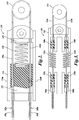
- the steering system tension control device 120 includes a slide block 122, which is disposed in a sliding engagement within a constraining structure 124.
- the slide block 122 is a pressure transfer member that transfers the pressure imparted by an outer sheath to a spring.
- the slide block 122 is one implementation of the pressure transfer member.
- the pressure transfer member, or slide block 122 can be omitted so that direct contact is made between the outer sheath and the spring.
- the slide block 122 has a number of apertures for each respective control cable 102a and 102b.
- Each aperture has a first relative large diameter through which the outer sheaths 104a and 104b can pass.
- Each aperture includes a second, narrower diameter through which only the core wires 106a and 106b can pass. In this manner, the ends of the outer sheaths 104a and 104b can abut against the shoulders created between the first and second diameters to push on the slide block 122.
- the slide block 122 travels within the confines of the constraining structure 124.
- a constraining structure 124 can have two side walls 126a and 126b between which the slide block 122 is retained that allows the slide block 122 to travel in a linear path.
- the side walls 126a and 126b can be attached to one half of the handle 118 housing (not shown), or alternatively, the side walls 126a and 126b can be molded directly as part of the handle 118 housing.
- the second half of the handle 118 housing (not shown) has features corresponding to the constraining structure 124, such that when the second half of the handle 118 housing is mated to the first, the slide block 122 is restrained on four sides by the sidewalls 126a and 126b and by the first and second halves of the handle 118 housing.
- a compression spring 128 is placed in contact with the slide block 122 on the opposite side to the outer sheaths 104a and 104b. The opposite end of the spring 128 rests against an immovable abutment 129.
- the spring 128 can be connected to a roller (cam follower) which is in contact with a cam surface as further described below.
- Such action relieves the compression on one or both of the outer sheaths 104a and 104b, relieving the tension on the core wires 106a and 106b and making them easier to move.
- the tension in the core wires 106a and 106b is not allowed to exceed a predetermined limit that is set by the counteracting force of spring 128.
- the spring 128 stiffness is selected so that it can withstand (without compression) the tension applied to the core wires 106a and 106b by the user during regular steering to bend the tip (especially at low looping configurations), but will compress to relieve tension on the steering cables as the insertion tube of the scope begins to bend and loop, as it is advanced further into the anatomy. As the insertion tube loops, the four cables are looped, or significantly bent, and significant tension builds up and the spring compresses to relieve the tension.
- the slide block 122 and the surfaces of the walls against which the slide block 122 slides can be made from, or covered with, a naturally lubricious material, such as a polyfluoro-carbon polymer, such as polytetrafluoroethylene (TEFLON®) or a polyamide to reduce the friction between the slide block 122 and the sliding surfaces.
- a naturally lubricious material such as a polyfluoro-carbon polymer, such as polytetrafluoroethylene (TEFLON®) or a polyamide to reduce the friction between the slide block 122 and the sliding surfaces.
- rails can be designed into the four walls to minimize the contact between the block and the housing to minimize friction forces by reducing the area of contact and hence ensuring that the block slides freely.
- This design of the tension relieving mechanism is particularly suited for low cost disposable devices. There are no complex machined or high precision parts. Cost springs (which are readily available and cheap) and a molded block can be used.
- the steering system tension control device 120 is illustrated as being located in the handle 116 of the endoscope and has a spring 128 to act against the proximal ends of the outer sheaths 104a and 104b, an embodiment can have springs that act against the distal ends of the outer sheaths 104a and 104b at the distal end of the shaft.
- the spring stiffness is designed to compress during shaft looping or bending and relieve tension in the core wires 106a and 106b.
- the outer sheaths 104a and 104b can be divided into two or more sections from the distal location to the proximal location.
- One or more springs can be disposed in the "breaks" between sections of the outer sheaths.
- each section of the outer sheath has intermediate ends against which a spring can be disposed to act against and between two sections of the same control cable.
- springs therefore, can be disposed on a single control cable.
- a helical spring is a representative spring.
- Alternative springs include leaf springs, elastomer materials, gas or fluid-filled chambers with pistons, compressed air chambers, or the like having characteristic spring-like behavior.
- the exemplary steering tension control system shown in FIGURE 2 uses a single spring for all of the control cables, it will be appreciated that it is possible to use multiple springs, such as a single spring per control cable wherein the core wire is passed through the center of the spring such that the end of the spring can rest against the end of the outer sheath. The opposite end of the spring would then rest against a fixed support. It is possible to also have more than one spring per control cable and more than one control cable per spring. Furthermore, springs can be disposed at any location along the length of the control cable, including the proximal and distal ends, and also at intermediate ends where the control cable is divided into more than one section. The distal, proximal, or intermediate spring configurations have the ability to relieve tension in the control cable or cables and allow compression of a spring when the compression due to looping of the outer sheath exceeds the counteracting force of the spring.
- the outer sheath can be made from a tightly wound coil material. Therefore, one inexpensive method of placing springs in one or various sections of the sheath is to wind a coil with variable pitch at locations in the coil that can be used for the sheath and the spring or springs by separating the loops of the coil.
- the windings of the outer sheath may be spread apart to form a compressible spring that compresses under the force built up as the outer sheath is looped within the body.
- the windings of the outer sheath also act as springs in addition to or as an alternative to the slide block and spring configuration.
- FIGURES 1 and 2 illustrate a first and a second control cable
- the present invention can be implemented using from at least two control cables to as many as desired.
- the single control cable can be configured with a return spring.
- the return spring applies constant tension to continually bias the distal tip in one direction, while the single control cable is actuated to bias the distal tip in the opposite direction.
- Any steering system with an odd or even number of control cables can be utilized.
- two control cables can be paired to act against one another. Having more than one pair of control cables can necessitate the use of an additional spool and corresponding dial on the handle.
- FIGURE 3 illustrates another exemplary steering system tension control device.
- the core wire of each of the control cables 102a and 102b can also have tension relief.
- the core wires 106a and 106b are connected to a spring 132a and 132b, respectively, to provide tension relief for the core wire instead of, or in addition to, a spring that provides for compression relief on the outer sheaths 104a and 104b.
- each core wire 106a and 106b is connected to a first slide block 138a and 138b, respectively.
- the slide blocks 138a and 138b are further connected to the springs 132a and 132b, respectively.
- the springs 132a and 132b are connected to a second set of slide blocks 140a and 140b, respectively, and the slide blocks 140a and 140b are connected to short sections of wire 134a and 134b, respectively, which are ultimately connected to the spool 114 in the manner described above. Therefore, in this steering system tension control device, if there is excessive tension on the core wires 106a and 106b, the tension can be relieved by the springs 132a and 132b. In this case, the springs 132a and 132b work, not in compression, but in expansion to relieve tension.
- the spring constant of springs 132a and 132b should be fairly high so as to avoid excessive play when the steering control dial 118 is turned, and so that the distal tip 112 articulates even for small movements of the dial 118.
- the tension relief on the core wires 106a and 106b is in addition to or, alternatively, as a substitute for, compression relief on the outer sheaths 104a and 104b.
- the tension springs 132a and 132b should be of adequately high stiffness to avoid any elongation at low looping configurations. However, the springs 132a and 132b should elongate as required to reduce tension when loops build up in the core wires 106a and 106b.
- FIGURE 4 illustrates another exemplary steering system tension control device. It is often desirable to have four degrees of freedom when steering the distal tip 112 of the endoscope shaft 108. To this end, two pairs of control cables are used.
- a single slide block 152 can be made to accept four control cables 154a, 154b, 154c, and 154d, wherein the outer sheath of each control cable 154a, 154b, 154c, and 154d is made to abut against the slide block 152, but with the core wires 156a, 156b, 156c, and 156d passing through the slide block 152.
- Each core wire 156a, 156b, 156c, and 156d is connected to one of two spools with its respective paired core wire.
- a central spring 158 abuts against the slide block 152 to provide for tension relief in any one or all of the four outer sheaths of the four control cables 154a, 154b, 154c, and 154d.
- the steering system tension control device of FIGURE 4 in addition to other spring configuration embodiments, can also be provided at the distal end of the outer sheaths so that the spring 158 is disposed to act against the proximal ends of the outer sheaths, or alternatively, between sections of the outer sheaths so that the spring 158 is disposed to act against ends in the outer sheath that are between the proximal end of the outer sheath and the distal end of the outer sheath.
- the spring 158 can be rigidly affixed at the end opposite to the slide block 152, or the spring 158 can be connected to a roller which is in contact with a cam surface, as further described below.
- a single spring 158 is used to relieve tension on the two pairs of control wires 154a, 154b, 154c, and 154d. This has the advantage that during steering, the two inactive cables also assist in relieving tension.
- the spring is acting as a compressible member.
- a less expensive version of the design involves a compressible block made of polypropylene, or similar material, in the handle of the device to anchor the outer sheaths. The thickness of the block and the durometer of the material can be adjusted to give the required elastic compression/deflection to relieve tension on the control cables during looping or significant bending of the shaft.
- FIGURE 5 illustrates an embodiment of a steering system tension control device in accordance with the present invention.
- slide blocks 160a and 160b are provided for control cables 102a and 102b, respectively.
- Slide blocks 160a and 160b abut against springs 162a and 162b, respectively.
- the slide blocks 160a and 160b accept the outer sheaths 104a and 104b that abut against the slide blocks 160a and 160b, but the core wires 106a and 106b are allowed to pass through the respective slide blocks 160a and 160b.
- the springs 162a and 162b may be fixed rigidly, as shown, or each spring 162a and 162b can be connected to a roller in contact with a cam surface, as described below.
- FIGURE 6 illustrates another embodiment of a steering system tension control device having a cam system in accordance with the present invention.
- the end of any spring thus far described that is opposite to a slide block 176 is connected to a roller 172 (cam follower).
- the roller 172 can rotate about its axis, but can also translate linearly. Thus, with translation of the roller 172 forwards and backwards, the amount of spring 170 compression can be adjusted.
- the roller 172 is in contact with a surface of a lobed cam 174.
- the cam 174 may be connected to a dial or a lever (not shown) that is manipulated from the outside of the handle 116 to rotate the cam 174.
- Rotation of the cam 174 therefore, causes the roller 172 to translate linearly forwards and backwards depending on the position of the cam 174.
- the roller 172 and cam 174 are in contact with each other when the radius from the axis of the cam 174 to the contact point with the roller 172 is at its shortest distance.
- the cam 174 is rotated in a counterclockwise direction, the radius from the axis of rotation of the cam 174 to the contact point will increase, thus pushing the roller 172 against the spring 170, which in turn compresses the spring 170 and applies a greater force on the slide block 176.
- This embodiment can adjust the amount of tension for any particular situation with the turn of a dial.
- the spring 170 can be adjusted to the lowest spring compression setting (as illustrated) to allow for the maximum tension relief.
- the cam 174 can be rotated to the highest spring compression setting and provide the least amount of tension relief and ensure no deadband in the response of the tip.
- the cam's 174 surface in contact with the roller 172 can be shaped to give an exponential increase in the spring's 170 stiffness. Alternatively, the increase in the stiffness can be linearly related to the cam's 174 surface.
- the physician can rotate the dial to any position therebetween to reduce tension in the control cables as loops build up in the shaft during a procedure. As the physician begins to feel the tension increasing in the control dial, the physician can adjust the cam and reduce the forces. As the physician withdraws the shaft and removes the loops, he could then rotate the dial in the opposite direction and take up the slack again.
- An additional advantage of this embodiment is that it allows physicians to adjust the tightness of the steering system and, hence, their ability to detect external forces acting on the tip, based on their particular preference. Physicians have different preferences regarding what the optimum tension in an endoscope steering system should be. Some users like to have a tensioned system that will be responsive to small movements of the dials. Other users prefer a looser feel so that they can detect external forces easier.
- Another embodiment of this design has the sliding block that anchors the outer sheaths connected directly to the cam without a spring. By rotating a lever on the outside of the handle, the physician can control the location of the block and, hence, the tension in the steering cables.
- stiffness of a spring of any outer sheath or core wire of the embodiments described above can be calculated through designs of experiments by conducting testing at low and high looping configurations. To gauge a suitable spring stiffness, the following general guidelines are provided.
- a suitable shaft has very little, if any, looseness in the control cables at low looping configurations and prevents tension from building up to ensure low steering torques at high looping configurations (21 ⁇ 4 to 3 loops, where each loop is 360°).
- a suitable compression spring is designed to compress and compensate for the increase in length of the outer sheath as more bends are made in the shaft to substantially keep the core wire path length constant. During low looping configurations, the compression spring is stiff enough to withstand the articulation forces transmitted through the steering dial(s).
- the spring can be preloaded (i.e., applying a force) with about 0.5 N/mm (3 lbs./in.) to about 1.4 N/mm (8 lbs./in.), or about 0.7 N/mm (4 lbs./in.) to about 1.2 N/mm (7 lbs./in.), or preferably, about 0.7 N/mm (4 lbs./in.) to about 1.1 N/mm (6 lbs./in.), where 0.9 N/mm (5 lbs./in.) can be preferred.
- the preload can reach 10% of the spring force. It can be appreciated that the optimum spring stiffness can depend on many factors, such as the bending stiffness of the tip, the stiffness of the outer sheath and core wire combined, and the number of loops expected during a procedure.
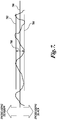
- FIGURE 7 a graph illustrating the range of tension of steerable medical devices without a tension relieving device is illustrated.
- Steerable medical devices having no tension relieving device are manufactured having an initial variation in the tension.
- the lower boundary is represented by the line 704, while the upper boundary is represented by the line 702.
- the range in variation between the lower boundary 704 and the upper boundary 702 is indicated by the marker 708.
- the line 706 represents the median setting of the steerable medical devices so that, because of manufacturing variances, there are approximately half of the medical devices above the median 706 and half of the medical devices below the median 706.
- the medical devices above the median 706 are those devices that have higher tension than the median, while those medical devices that are below the median 706 will be slacker than the median.
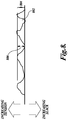
- FIGURE 8 a graph illustrating the range of tension of steerable medical devices with a tension relieving device in accordance with one embodiment of the present invention, wherein the tension relieving device spring is preloaded at an initial setting, is illustrated.
- the variation is reduced in comparison to those steerable medical devices without a tension relieving device illustrated in FIGURE 7 .
- steerable medical devices with a preloaded spring half of the devices which are slacker than the median can be eliminated.
- the medical devices with a preloaded tension relieving spring have a much more narrow band of variation 804 extending from the line 802 representing medical devices with no slack, to the top of the range of variation indicated by marker 806.
- the band 804 is the expected variation in the manufacturing process. Therefore, the optimal setting for medical devices with a tension relieving spring can be in the area within the band 804. In this area, the medical devices will be responsive and have no slack.
- steerable medical devices can be designed to have a small amount of compression of the spring (and therefore tension in the system at all times).
- the method of manufacturing such devices would include applying an initial preload in the spring to take up the slack in the cables in the preload ranges described above.
- the steering system tension control device serves as a buffer, widens the range of optimal initial tensioning settings, and ensures a consistent feel on the steerable medical device. This prevents having to individually tension each scope and reduces manufacturing costs. For example, precise tension measurement systems are no longer required.
Landscapes
- Health & Medical Sciences (AREA)
- Life Sciences & Earth Sciences (AREA)
- Surgery (AREA)
- Biomedical Technology (AREA)
- Medical Informatics (AREA)
- Optics & Photonics (AREA)
- Pathology (AREA)
- Radiology & Medical Imaging (AREA)
- Biophysics (AREA)
- Engineering & Computer Science (AREA)
- Physics & Mathematics (AREA)
- Heart & Thoracic Surgery (AREA)
- Nuclear Medicine, Radiotherapy & Molecular Imaging (AREA)
- Molecular Biology (AREA)
- Animal Behavior & Ethology (AREA)
- General Health & Medical Sciences (AREA)
- Public Health (AREA)
- Veterinary Medicine (AREA)
- Instruments For Viewing The Inside Of Hollow Bodies (AREA)
- Flexible Shafts (AREA)
Description
- The present invention relates to medical instruments in general, and to instruments with steerable shafts in particular.
- As an alternative to performing more invasive medical procedures, many physicians are utilizing endoscopes and catheters to perform diagnostic and therapeutic procedures on the internal tissues of patients. With this less invasive approach, a medical instrument, such as an endoscope or a catheter is advanced to a site of interest in order to perform the indicated procedure. Most endoscopes and catheters have a flexible shaft that allows the endoscope or catheter to wind its way through bends in the patient's anatomy until it reaches the tissue of interest. In order to advance the flexible shaft, most steerable endoscopes have a system of control cables that act in pairs to help direct the distal tip of the shaft. Each control cable is disposed opposite to its pair, and the control cables move in opposition to one another such that as one control cable is being pulled, the other is being released. The effect is to bend the tip of the shaft in a desired direction. In many endoscopes or catheters, the control cables have an outer sheath and an inner core wire. The outer sheath acts to transmit the longitudinal motion of the core wire to the distal tip of the endoscope. During a medical procedure, it is not uncommon for the shaft to form one or more loops as it is navigated to the tissue of interest. When a shaft including a control cable is looped, the outer sheath becomes increasingly stiff and harder to navigate within the body. At every bend of the shaft, the distances traveled by the core wire and its respective outer sheath differ, producing tension in the outer sheath and/or the core wire and increasing the amount of force needed to exert longitudinal force in the pull wire. This results in the user having less control over the tip of the device and less ability to detect external forces acting on the tip. Therefore, there is a need for a navigation system for use in steerable medical instruments that is still steerable at low forces if looped in the body.
-
EP 0 165 718 A discloses an endoscope having an insertion tube constructed from a plurality of disks strung together on steering cables and received in a flexible plastics sheath. Each disk is formed with a plurality of service apertures defining a plurality of service passages of equal diameter within the chain of disks. The cable apertures in the disks are skewed so that each cable follows a helical path along the length of the insertion tube. -
US 4 762 118 A discloses a self-adjusting steering mechanism for a borescope, endoscope, or guide tube. -
US 2004/0186350 A1 discloses an apparatus for guiding an endoscope during an endoluminal procedure via one or rigidizable wires. -
US 5 448 989 A discloses a shaft for medical instruments, especially for guiding instruments into body cavities, which has neighboring segments that are hollow on the inside and that form sections of the shaft. The segments can be adjusted in their positions by means of control wires so that various shaft curvatures can be set, whereby at least two groups of segments can be adjusted independently of one another. -
WO 93/20742 A - A steerable medical instrument as recited in independent claim 1 is provided. The dependent claims define embodiments.
- The present invention is an elongated medical instrument including a shaft that is steerable in a desired direction. Control cables in the shaft include an outer sheath and an inner core wire that is tensioned to articulate the distal tip of the shaft. To address the problems described above, the ends of the control cable are in contact with a steering system tension control device so that tension in the control cable created as a result of loops or bends in the shaft is relieved.
- This summary is provided to introduce a selection of concepts in a simplified form that are further described below in the Detailed Description. This summary is not intended to identify key features of the claimed subject matter, nor is it intended to be used as an aid in determining the scope of the claimed subject matter.
- The foregoing aspects and many of the attendant advantages of this invention will become more readily appreciated as the same become better understood by reference to the following detailed description, when taken in conjunction with the accompanying drawings, wherein:
-
FIGURE 1 is an illustration of an endoscope including a steering system tension control device according to an embodiment of the present invention; -
FIGURE 2 is an illustration of an exemplary steering system tension control device; -
FIGURE 3 is an illustration of another exemplary steering system tension control device; -
FIGURE 4 is an illustration of another exemplary steering system tension control device; -
FIGURE 5 is an illustration of a steering system tension control device of a steerable medical instrument according to an embodiment of the present invention; and -
FIGURE 6 is an illustration of another steering system tension control device of a steerable medical instrument according to an embodiment of the present invention. -
FIGURE 7 is a graph representing steerable medical devices without a tension relieving device; and -
FIGURE 8 is a graph representing steerable medical devices with a tension relieving device. - As indicated above, the present invention is a device for relieving tension that occurs in control cables of steerable medical instruments as a result of loops and bends in the instrument. Although the disclosed embodiments are shown for use in an endoscope, it will be appreciated that the invention may be used in any steerable medical instrument, such as catheters for vascular, urological, and laparoscopic applications or the like.
-
FIGURE 1 illustrates anendoscope 100 including a steering systemtension control device 120 made in accordance with one embodiment of the present invention. Not all of the features of theendoscope 100 are being illustrated for brevity. Theendoscope 100 includes ahandle 116 that is connected to ashaft 108 having aproximal end 110 and adistal end 112. Thehandle 116 is connected to theproximal end 110 of theshaft 108. A pair ofcontrol cables distal end 112 of theshaft 108. Thecontrol cables outer sheath flexible core wire outer sheath core wires outer sheaths shaft 108 to a proximal location and terminate within the interior of the handle 102. Thecore wires outer sheaths outer sheaths core wires handle 116 to the distal tip of theshaft 108. Theouter sheaths outer sheaths core wires outer sheaths shaft 108. Theouter sheaths handle 116 in a steering systemtension control device 120, as discussed further below. - The
core wires distal tip 112 of theshaft 108 to aspool 114 within the interior and at the proximal end of thehandle 116. Thespool 114 is connected to arotatable knob dial 118 that is exterior to thehandle 116. Thedial 118 can be turned clockwise or counterclockwise to rotate thespool 114. The distal ends of thecore wires distal tip 112 of theshaft 108. The proximal ends of thecore wires spool 114. For example, thecore wires spool 114. Alternatively, thecore wires spool 114. In one embodiment, thecore wires spool 114. In yet another embodiment, thecore wires spool 114. Thecore wires distal tip 112 and to thespool 114 via an enlarged head or a barrel-like member, similar to a bicycle brake cable, that is inserted within a mating slot that enables the core wires to be removed. Thecore wires outer sheaths dial 118 and thespool 114. The rotation of thedial 118 andspool 114 results in one or more of the core wires being tensioned. For example, inFIGURE 1 , by rotating thedial 118 clockwise, thecore wire 106b is released, and thecore wire 106a is tensioned. Therefore,core wire 106a pulls on thedistal tip 112, while thecore wire 106b is released to allow thedistal tip 112 to bend. By selectively tensioning one or more of the core wires at thedistal tip 112, the distal end of theshaft 108 will bend in the direction corresponding to the tensioning forces. If the entire length of theshaft 108 is straight and does not have any bends in it, the friction of thecore wires outer sheaths shaft 108, which is not uncommon in actual use, theshaft 108 may become difficult to steer due to the increase in tension as a result of the differences in the distances that the outer sheaths and core wires must travel around the bends or loops and the friction between theouter sheaths core wires - In order to relieve tension in the cables, one embodiment of the invention includes a steering system tension control device. As best seen in
FIG. 2 , which illustrates an exemplary steering systemtension control device 120, the steering systemtension control device 120 includes aslide block 122, which is disposed in a sliding engagement within a constrainingstructure 124. Theslide block 122 is a pressure transfer member that transfers the pressure imparted by an outer sheath to a spring. Theslide block 122 is one implementation of the pressure transfer member. The pressure transfer member, orslide block 122, can be omitted so that direct contact is made between the outer sheath and the spring. Theslide block 122 has a number of apertures for eachrespective control cable outer sheaths core wires outer sheaths slide block 122. Theslide block 122 travels within the confines of the constrainingstructure 124. A constrainingstructure 124 can have twoside walls slide block 122 is retained that allows theslide block 122 to travel in a linear path. Theside walls handle 118 housing (not shown), or alternatively, theside walls handle 118 housing. The second half of thehandle 118 housing (not shown) has features corresponding to the constrainingstructure 124, such that when the second half of thehandle 118 housing is mated to the first, theslide block 122 is restrained on four sides by thesidewalls handle 118 housing. - A
compression spring 128 is placed in contact with theslide block 122 on the opposite side to theouter sheaths spring 128 rests against animmovable abutment 129. Alternatively, thespring 128 can be connected to a roller (cam follower) which is in contact with a cam surface as further described below. When one or bothouter sheaths spring 128, theslide block 122 will give and slide to compress thespring 128. Such action relieves the compression on one or both of theouter sheaths core wires core wires spring 128. Thespring 128 stiffness is selected so that it can withstand (without compression) the tension applied to thecore wires - The
slide block 122 and the surfaces of the walls against which theslide block 122 slides can be made from, or covered with, a naturally lubricious material, such as a polyfluoro-carbon polymer, such as polytetrafluoroethylene (TEFLON®) or a polyamide to reduce the friction between theslide block 122 and the sliding surfaces. Alternatively, rails can be designed into the four walls to minimize the contact between the block and the housing to minimize friction forces by reducing the area of contact and hence ensuring that the block slides freely. - This design of the tension relieving mechanism is particularly suited for low cost disposable devices. There are no complex machined or high precision parts. Cost springs (which are readily available and cheap) and a molded block can be used.
- While the steering system
tension control device 120 is illustrated as being located in thehandle 116 of the endoscope and has aspring 128 to act against the proximal ends of theouter sheaths outer sheaths core wires outer sheaths - Although the exemplary steering tension control system shown in
FIGURE 2 uses a single spring for all of the control cables, it will be appreciated that it is possible to use multiple springs, such as a single spring per control cable wherein the core wire is passed through the center of the spring such that the end of the spring can rest against the end of the outer sheath. The opposite end of the spring would then rest against a fixed support. It is possible to also have more than one spring per control cable and more than one control cable per spring. Furthermore, springs can be disposed at any location along the length of the control cable, including the proximal and distal ends, and also at intermediate ends where the control cable is divided into more than one section. The distal, proximal, or intermediate spring configurations have the ability to relieve tension in the control cable or cables and allow compression of a spring when the compression due to looping of the outer sheath exceeds the counteracting force of the spring. - In another embodiment, the outer sheath can be made from a tightly wound coil material. Therefore, one inexpensive method of placing springs in one or various sections of the sheath is to wind a coil with variable pitch at locations in the coil that can be used for the sheath and the spring or springs by separating the loops of the coil. For example, the windings of the outer sheath may be spread apart to form a compressible spring that compresses under the force built up as the outer sheath is looped within the body. In this embodiment, the windings of the outer sheath also act as springs in addition to or as an alternative to the slide block and spring configuration.
- While
FIGURES 1 and2 illustrate a first and a second control cable, it is to be appreciated that the present invention can be implemented using from at least two control cables to as many as desired. In an exemplary steering system with one control cable, for example, the single control cable can be configured with a return spring. The return spring applies constant tension to continually bias the distal tip in one direction, while the single control cable is actuated to bias the distal tip in the opposite direction. Any steering system with an odd or even number of control cables can be utilized. In systems having an even number of control cables, two control cables can be paired to act against one another. Having more than one pair of control cables can necessitate the use of an additional spool and corresponding dial on the handle. -
FIGURE 3 illustrates another exemplary steering system tension control device. In certain situations, the core wire of each of thecontrol cables core wires spring outer sheaths core wire first slide block springs springs slide blocks wire spool 114 in the manner described above. Therefore, in this steering system tension control device, if there is excessive tension on thecore wires springs springs springs steering control dial 118 is turned, and so that thedistal tip 112 articulates even for small movements of thedial 118. The tension relief on thecore wires outer sheaths springs core wires -
FIGURE 4 illustrates another exemplary steering system tension control device. It is often desirable to have four degrees of freedom when steering thedistal tip 112 of theendoscope shaft 108. To this end, two pairs of control cables are used. Asingle slide block 152 can be made to accept fourcontrol cables control cable slide block 152, but with thecore wires slide block 152. Eachcore wire central spring 158 abuts against theslide block 152 to provide for tension relief in any one or all of the four outer sheaths of the fourcontrol cables FIGURE 4 , in addition to other spring configuration embodiments, can also be provided at the distal end of the outer sheaths so that thespring 158 is disposed to act against the proximal ends of the outer sheaths, or alternatively, between sections of the outer sheaths so that thespring 158 is disposed to act against ends in the outer sheath that are between the proximal end of the outer sheath and the distal end of the outer sheath. Thespring 158 can be rigidly affixed at the end opposite to theslide block 152, or thespring 158 can be connected to a roller which is in contact with a cam surface, as further described below. - Furthermore, a
single spring 158 is used to relieve tension on the two pairs ofcontrol wires - It is also appreciated that the spring is acting as a compressible member. A less expensive version of the design involves a compressible block made of polypropylene, or similar material, in the handle of the device to anchor the outer sheaths. The thickness of the block and the durometer of the material can be adjusted to give the required elastic compression/deflection to relieve tension on the control cables during looping or significant bending of the shaft.
-
FIGURE 5 illustrates an embodiment of a steering system tension control device in accordance with the present invention. In this embodiment,slide blocks control cables Slide blocks springs outer sheaths core wires respective slide blocks springs spring -
FIGURE 6 illustrates another embodiment of a steering system tension control device having a cam system in accordance with the present invention. The end of any spring thus far described that is opposite to aslide block 176 is connected to a roller 172 (cam follower). Theroller 172 can rotate about its axis, but can also translate linearly. Thus, with translation of theroller 172 forwards and backwards, the amount ofspring 170 compression can be adjusted. Theroller 172 is in contact with a surface of alobed cam 174. Thecam 174 may be connected to a dial or a lever (not shown) that is manipulated from the outside of thehandle 116 to rotate thecam 174. Rotation of thecam 174 therefore, causes theroller 172 to translate linearly forwards and backwards depending on the position of thecam 174. For example, as illustrated, theroller 172 andcam 174 are in contact with each other when the radius from the axis of thecam 174 to the contact point with theroller 172 is at its shortest distance. However, when thecam 174 is rotated in a counterclockwise direction, the radius from the axis of rotation of thecam 174 to the contact point will increase, thus pushing theroller 172 against thespring 170, which in turn compresses thespring 170 and applies a greater force on theslide block 176. This embodiment can adjust the amount of tension for any particular situation with the turn of a dial. For example, in high looping configurations, thespring 170 can be adjusted to the lowest spring compression setting (as illustrated) to allow for the maximum tension relief. In low looping configurations, thecam 174 can be rotated to the highest spring compression setting and provide the least amount of tension relief and ensure no deadband in the response of the tip. - Small package footprints are advantageous to minimize storage space for disposable endoscopes in the physician's lab. Having a small footprint requires putting several loops in the shaft of the endoscope which in turn builds up significant tension in the closed loop steering systems. This embodiment allows the cam to be set to the lowest spring compression setting during packaging, transport, and storage. This will maintain low forces on the plastic parts of the handle and minimize effects of creep.
- The cam's 174 surface in contact with the
roller 172 can be shaped to give an exponential increase in the spring's 170 stiffness. Alternatively, the increase in the stiffness can be linearly related to the cam's 174 surface. The physician can rotate the dial to any position therebetween to reduce tension in the control cables as loops build up in the shaft during a procedure. As the physician begins to feel the tension increasing in the control dial, the physician can adjust the cam and reduce the forces. As the physician withdraws the shaft and removes the loops, he could then rotate the dial in the opposite direction and take up the slack again. An additional advantage of this embodiment is that it allows physicians to adjust the tightness of the steering system and, hence, their ability to detect external forces acting on the tip, based on their particular preference. Physicians have different preferences regarding what the optimum tension in an endoscope steering system should be. Some users like to have a tensioned system that will be responsive to small movements of the dials. Other users prefer a looser feel so that they can detect external forces easier. - Another embodiment of this design has the sliding block that anchors the outer sheaths connected directly to the cam without a spring. By rotating a lever on the outside of the handle, the physician can control the location of the block and, hence, the tension in the steering cables.
- The stiffness of a spring of any outer sheath or core wire of the embodiments described above can be calculated through designs of experiments by conducting testing at low and high looping configurations. To gauge a suitable spring stiffness, the following general guidelines are provided.
- About 20° of play on the
dial 118 appears to be the limit that is acceptable to most physicians. A suitable shaft has very little, if any, looseness in the control cables at low looping configurations and prevents tension from building up to ensure low steering torques at high looping configurations (2¼ to 3 loops, where each loop is 360°). A suitable compression spring is designed to compress and compensate for the increase in length of the outer sheath as more bends are made in the shaft to substantially keep the core wire path length constant. During low looping configurations, the compression spring is stiff enough to withstand the articulation forces transmitted through the steering dial(s). One optimum spring stiffness appears to be in the range of about 10.5 N/mm (60 lbs./in.) to about 17.5 N/mm (100 lbs./in). In one embodiment, the spring can be preloaded (i.e., applying a force) with about 0.5 N/mm (3 lbs./in.) to about 1.4 N/mm (8 lbs./in.), or about 0.7 N/mm (4 lbs./in.) to about 1.2 N/mm (7 lbs./in.), or preferably, about 0.7 N/mm (4 lbs./in.) to about 1.1 N/mm (6 lbs./in.), where 0.9 N/mm (5 lbs./in.) can be preferred. The preload can reach 10% of the spring force. It can be appreciated that the optimum spring stiffness can depend on many factors, such as the bending stiffness of the tip, the stiffness of the outer sheath and core wire combined, and the number of loops expected during a procedure. - An additional benefit of this tension relieving system is that there is a broader range of tensioning as shown by comparing
FIGURES 7 and8 . - Referring to
FIGURE 7 , a graph illustrating the range of tension of steerable medical devices without a tension relieving device is illustrated. Steerable medical devices having no tension relieving device are manufactured having an initial variation in the tension. The lower boundary is represented by theline 704, while the upper boundary is represented by theline 702. The range in variation between thelower boundary 704 and theupper boundary 702 is indicated by themarker 708. Theline 706 represents the median setting of the steerable medical devices so that, because of manufacturing variances, there are approximately half of the medical devices above the median 706 and half of the medical devices below the median 706. The medical devices above the median 706 are those devices that have higher tension than the median, while those medical devices that are below the median 706 will be slacker than the median. The range in variation is not suitable because it leads to inconsistent tension. Without a spring, there is only one optimal setting at the neutral point between tension and slack. If the system is tighter than this, then there is significant additional tension in the system which will require higher forces to steer. If looser than the neutral point, then the medical devices will have a sloppy feel and will not be responsive to minor movements of the dial. This design would require exact tensioning of each individual medical device by the physician or by the manufacturer, leading to inefficiencies. - Referring to
FIGURE 8 , a graph illustrating the range of tension of steerable medical devices with a tension relieving device in accordance with one embodiment of the present invention, wherein the tension relieving device spring is preloaded at an initial setting, is illustrated. In the case where steerable medical devices are fitted with a tension relieving device and have an initial preload in the spring, the variation is reduced in comparison to those steerable medical devices without a tension relieving device illustrated inFIGURE 7 . In the case of steerable medical devices with a preloaded spring, half of the devices which are slacker than the median can be eliminated. The medical devices with a preloaded tension relieving spring have a much more narrow band ofvariation 804 extending from theline 802 representing medical devices with no slack, to the top of the range of variation indicated bymarker 806. Theband 804 is the expected variation in the manufacturing process. Therefore, the optimal setting for medical devices with a tension relieving spring can be in the area within theband 804. In this area, the medical devices will be responsive and have no slack. With a tension relieving device having a preloaded spring in the steering system, there is a much wider optimal range of initial tensioning in the ranges discussed above. Therefore, steerable medical devices can be designed to have a small amount of compression of the spring (and therefore tension in the system at all times). This helps to ensure that the steerable medical devices have a similar feel and reduces the effect of device-to-device variations during manufacturing. The method of manufacturing such devices would include applying an initial preload in the spring to take up the slack in the cables in the preload ranges described above. The steering system tension control device serves as a buffer, widens the range of optimal initial tensioning settings, and ensures a consistent feel on the steerable medical device. This prevents having to individually tension each scope and reduces manufacturing costs. For example, precise tension measurement systems are no longer required. - While illustrative embodiments have been illustrated and described, it will be appreciated that various changes can be made therein without departing from the scope of the invention. Therefore, the present invention is to be determined from the following claims and equivalents thereof.
Claims (7)
- A steerable medical instrument (100) comprising:a shaft (108);control cables comprising a first control cable (102a) and a second control cable (102b) disposed within the shaft (108) of the medical instrument (100) that are selectively tensioned to steer a tip (112) of the medical instrument (100), each of the first and second control cables (102a, 102b) having a core wire (106a, 106b) surrounded by an outer sheath (104a, 104b);a first spring (162a);a second spring (162b);a first block (160a) that engages the outer sheath (104a) of the first control cable (102a) and allows the core wire (106a) of the first control cable (102a) to pass through the first block (160a), wherein the first block (160a) is slidingly fitted in a container (124) having side walls (126a, 126b) that engage the first block (160a) preventing the first block (160a) from moving laterally while allowing the first block (160a) to move along the core wire (106a) of the first control cable (102a); anda second block (160b) that engages the outer sheath (104b) of the second control cable (102b) and allows the core wire (106b) of the second control cable (102b) to pass through the second block (160b), wherein the second block (160b) is slidingly fitted in the container (124) and wherein the side walls (126a, 126b) of the container (124) engage the second block (160b) preventing the second block (160b) from moving laterally while allowing the second block (160b) to move along the core wire (106b) of the second control cable (102b),wherein the first spring (162a) is disposed to engage the first block (160a) against an end of the outer sheath (104a) of the first control cable (102a) and the second spring (162b) is disposed to engage the second block (160b) against an end of the outer sheath (104b) of the second control cable (102b).
- The steerable medical instrument of Claim 1, wherein an end of the first spring (162a) or of the second spring (162b) engages a cam (174) that is movable to change a compression of the spring (162a, 162b).
- The steerable medical instrument of Claim 1, wherein the first spring (162a) is disposed to act against a proximal end of the outer sheath (104a) of the first control cable (102a).
- The steerable medical instrument of Claim 1, wherein the first spring (162a) is disposed to act against an end of the outer sheath (104a) of the first control cable (102a) and the second spring (162b) is disposed to act against an end of the outer sheath (104b) of the second control cable (102b).
- The steerable medical instrument of claim 1, further comprising:a handle (116) including one or more controls that selectively orient a distal end (112) of the shaft (108);wherein the first and second control wires (102a, 102b) are tensioned by the one or more controls.
- The steerable medical instrument of Claim 5, wherein the first block (160a) is fitted within an enclosure in the handle (116), having the side walls (126a, 126b) that engage the first block (160a) and constrain movement of the first block (160a) to a direction in line with the core wire (106a) of the first control cable (102a), and wherein the second block (160b) is fitted within the enclosure in the handle (116), having the side walls (126a, 126b) that engage the second block (160b) and constrain movement of the second block (160b) to a direction in line with the core wire (106b) of the second control cable (102b).
- The steerable medical instrument of Claim 6, wherein the enclosure is molded into the handle (116).
Applications Claiming Priority (2)
| Application Number | Priority Date | Filing Date | Title |
|---|---|---|---|
| US11/394,645 US20070232858A1 (en) | 2006-03-31 | 2006-03-31 | Steering system tension control devices |
| PCT/US2007/062995 WO2007117783A1 (en) | 2006-03-31 | 2007-02-28 | Steering system tension control devices |
Publications (2)
| Publication Number | Publication Date |
|---|---|
| EP2007269A1 EP2007269A1 (en) | 2008-12-31 |
| EP2007269B1 true EP2007269B1 (en) | 2019-04-03 |
Family
ID=38323880
Family Applications (1)
| Application Number | Title | Priority Date | Filing Date |
|---|---|---|---|
| EP07757655.1A Active EP2007269B1 (en) | 2006-03-31 | 2007-02-28 | Steering system tension control devices |
Country Status (3)
| Country | Link |
|---|---|
| US (2) | US20070232858A1 (en) |
| EP (1) | EP2007269B1 (en) |
| WO (1) | WO2007117783A1 (en) |
Families Citing this family (105)
| Publication number | Priority date | Publication date | Assignee | Title |
|---|---|---|---|---|
| US20040199052A1 (en) | 2003-04-01 | 2004-10-07 | Scimed Life Systems, Inc. | Endoscopic imaging system |
| US7909873B2 (en) * | 2006-12-15 | 2011-03-22 | Soteira, Inc. | Delivery apparatus and methods for vertebrostenting |
| US9119633B2 (en) | 2006-06-28 | 2015-09-01 | Kardium Inc. | Apparatus and method for intra-cardiac mapping and ablation |
| US10028783B2 (en) | 2006-06-28 | 2018-07-24 | Kardium Inc. | Apparatus and method for intra-cardiac mapping and ablation |
| US8920411B2 (en) | 2006-06-28 | 2014-12-30 | Kardium Inc. | Apparatus and method for intra-cardiac mapping and ablation |
| US11389232B2 (en) | 2006-06-28 | 2022-07-19 | Kardium Inc. | Apparatus and method for intra-cardiac mapping and ablation |
| JP4267017B2 (en) * | 2006-10-05 | 2009-05-27 | オリンパスメディカルシステムズ株式会社 | Endoscope |
| US8906011B2 (en) | 2007-11-16 | 2014-12-09 | Kardium Inc. | Medical device for use in bodily lumens, for example an atrium |
| EP2067433B1 (en) * | 2007-12-03 | 2013-05-01 | Olympus Medical Systems Corp. | Medical appliance, endoscope overtube and endoscope apparatus |
| JP5144282B2 (en) * | 2007-12-03 | 2013-02-13 | オリンパスメディカルシステムズ株式会社 | Medical instruments |
| US20090287054A1 (en) * | 2008-05-19 | 2009-11-19 | Olympus Medical Systems Corp. | Bending tube and medical apparatus |
| US8968355B2 (en) * | 2008-08-04 | 2015-03-03 | Covidien Lp | Articulating surgical device |
| US8137308B2 (en) * | 2008-09-16 | 2012-03-20 | Biosense Webster, Inc. | Catheter with adjustable deflection sensitivity |
| US9259274B2 (en) | 2008-09-30 | 2016-02-16 | Intuitive Surgical Operations, Inc. | Passive preload and capstan drive for surgical instruments |
| US9339342B2 (en) * | 2008-09-30 | 2016-05-17 | Intuitive Surgical Operations, Inc. | Instrument interface |
| US20100121141A1 (en) * | 2008-11-12 | 2010-05-13 | Michael Rontal | Endoscopic cutting and debriding device mounted on a flexible and maneuverable tube employing a fluid-driven turbine |
| US10046141B2 (en) | 2008-12-30 | 2018-08-14 | Biosense Webster, Inc. | Deflectable sheath introducer |
| US20100280525A1 (en) * | 2009-04-29 | 2010-11-04 | Hansen Medical, Inc. | Flexible and steerable elongate instruments with shape control and support elements |
| US9254123B2 (en) * | 2009-04-29 | 2016-02-09 | Hansen Medical, Inc. | Flexible and steerable elongate instruments with shape control and support elements |
| US10080482B2 (en) * | 2009-06-30 | 2018-09-25 | Intuitive Surgical Operations, Inc. | Compliant surgical device |
| US8747351B2 (en) | 2009-08-28 | 2014-06-10 | Biosense Webster, Inc. | Catheter with multi-functional control handle having linear mechanism |
| US8974372B2 (en) | 2010-08-25 | 2015-03-10 | Barry M. Fell | Path-following robot |
| US9452016B2 (en) | 2011-01-21 | 2016-09-27 | Kardium Inc. | Catheter system |
| US11259867B2 (en) | 2011-01-21 | 2022-03-01 | Kardium Inc. | High-density electrode-based medical device system |
| CA2764494A1 (en) | 2011-01-21 | 2012-07-21 | Kardium Inc. | Enhanced medical device for use in bodily cavities, for example an atrium |
| US9486273B2 (en) | 2011-01-21 | 2016-11-08 | Kardium Inc. | High-density electrode-based medical device system |
| EP2732750B1 (en) * | 2011-07-11 | 2017-05-10 | Olympus Corporation | Endoscope |
| US20130190561A1 (en) | 2012-01-10 | 2013-07-25 | Boston Scientific Scimed, Inc. | Steerable medical device having an imaging system |
| JP5826862B2 (en) * | 2012-01-16 | 2015-12-02 | オリンパス株式会社 | Insertion device |
| USD777926S1 (en) | 2012-01-20 | 2017-01-31 | Kardium Inc. | Intra-cardiac procedure device |
| USD777925S1 (en) | 2012-01-20 | 2017-01-31 | Kardium Inc. | Intra-cardiac procedure device |
| JP6025401B2 (en) | 2012-05-31 | 2016-11-16 | キヤノン株式会社 | Medical instruments |
| US9010214B2 (en) | 2012-06-22 | 2015-04-21 | Board Of Regents Of The University Of Nebraska | Local control robotic surgical devices and related methods |
| US20140012075A1 (en) * | 2012-07-09 | 2014-01-09 | Gyrus Acmi, Inc., D.B.A. Olympus Surgical Technologies America | Sinus endoscope |
| US20140018620A1 (en) * | 2012-07-13 | 2014-01-16 | Fortimedix B.V. | Steerable tube for endoscopic applications |
| US9022976B2 (en) | 2012-10-30 | 2015-05-05 | St. Jude Medical, Atrial Fibrillation Division, Inc. | Push-coil steering mechanism |
| WO2014111943A2 (en) * | 2013-01-21 | 2014-07-24 | G.I. View Ltd. | Integrated steering device |
| US9968241B2 (en) * | 2013-02-22 | 2018-05-15 | Ambu A/S | Apparatus for maintaining a tensioned pull-wire in an endoscope |
| US20140352483A1 (en) * | 2013-06-04 | 2014-12-04 | General Electric Company | Remote alignment tool |
| EP3033035B1 (en) | 2013-08-15 | 2020-11-25 | Intuitive Surgical Operations, Inc. | Instrument sterile adapter drive features |
| KR102523090B1 (en) | 2013-08-15 | 2023-04-19 | 인튜어티브 서지컬 오퍼레이션즈 인코포레이티드 | Preloaded surgical instrument interface |
| CN108784838B (en) | 2013-08-15 | 2021-06-08 | 直观外科手术操作公司 | Instrument sterile adapter drive interface |
| KR102313240B1 (en) | 2013-08-15 | 2021-10-18 | 인튜어티브 서지컬 오퍼레이션즈 인코포레이티드 | Robotic instrument driven element |
| US10550918B2 (en) | 2013-08-15 | 2020-02-04 | Intuitive Surgical Operations, Inc. | Lever actuated gimbal plate |
| US10076348B2 (en) | 2013-08-15 | 2018-09-18 | Intuitive Surgical Operations, Inc. | Rotary input for lever actuation |
| CN105611891B (en) | 2013-08-15 | 2018-09-21 | 直观外科手术操作公司 | Variable Instrument Preload Mechanism Controller |
| AU2015240552B2 (en) | 2014-04-04 | 2019-04-04 | Boston Scientific Scimed, Inc. | Medical system and related methods for diagnosis and treatment |
| JP6284438B2 (en) * | 2014-06-12 | 2018-02-28 | オリンパス株式会社 | manipulator |
| CN111658180B (en) | 2014-08-15 | 2024-05-31 | 直观外科手术操作公司 | Surgical system with variable entry guide configuration |
| EP3185744B1 (en) * | 2014-08-29 | 2024-10-23 | EndoChoice, Inc. | Systems and methods for varying stiffness of an endoscopic insertion tube |
| CN105759418B (en) * | 2014-12-19 | 2019-06-28 | 深圳市锐丽视科技有限公司 | Flexible number endoscope |
| US10939808B2 (en) * | 2015-01-16 | 2021-03-09 | B-K Medical Aps | Articulation activation wire stress relief for an ultrasound imaging probe |
| CN107000220B9 (en) * | 2015-02-19 | 2020-04-17 | 奥林巴斯株式会社 | Manipulator and manipulator system |
| JP6713285B2 (en) * | 2016-01-18 | 2020-06-24 | オリンパス株式会社 | Endoscope |
| US10751136B2 (en) | 2016-05-18 | 2020-08-25 | Virtual Incision Corporation | Robotic surgical devices, systems and related methods |
| CN109195500A (en) * | 2016-05-31 | 2019-01-11 | 奥林巴斯株式会社 | flexible tube of endoscope |
| WO2018013316A1 (en) | 2016-07-14 | 2018-01-18 | Intuitive Surgical Operations, Inc. | Geared roll drive for medical instrument |
| US11890070B2 (en) | 2016-07-14 | 2024-02-06 | Intuitive Surgical Operations, Inc. | Instrument release |
| WO2018013298A1 (en) | 2016-07-14 | 2018-01-18 | Intuitive Surgical Operations, Inc. | Geared grip actuation for medical instruments |
| CN113995532B (en) | 2016-07-14 | 2024-11-01 | 直观外科手术操作公司 | Instrument irrigation system |
| CN109688960B (en) | 2016-07-14 | 2022-04-01 | 直观外科手术操作公司 | Multi-cable medical instrument |
| US20180028784A1 (en) | 2016-07-28 | 2018-02-01 | Cook Medical Technolgoies Llc | Control wire distal securement in steerable catheter |
| US10588495B2 (en) | 2016-07-28 | 2020-03-17 | Cook Medical Technologies LL | Brake mechanism of a steerable catheter |
| WO2018045036A1 (en) | 2016-08-30 | 2018-03-08 | Board Of Regents Of The University Of Nebraska | Robotic device with compact joint design and an additional degree of freedom and related systems and methods |
| WO2018094191A1 (en) | 2016-11-21 | 2018-05-24 | Intuitive Surgical Operations, Inc. | Cable length conserving medical instrument |
| US10357321B2 (en) | 2017-02-24 | 2019-07-23 | Intuitive Surgical Operations, Inc. | Splayed cable guide for a medical instrument |
| US11642014B2 (en) | 2017-03-08 | 2023-05-09 | Ambu A/S | Handle for an endoscope |
| EP3906837B1 (en) | 2017-03-08 | 2023-08-09 | Ambu A/S | Handle for an endoscope |
| CN110234263B (en) | 2017-03-08 | 2022-04-08 | 安布股份有限公司 | Handle for endoscope |
| US11076926B2 (en) | 2017-03-21 | 2021-08-03 | Intuitive Surgical Operations, Inc. | Manual release for medical device drive system |
| EP3618689A4 (en) * | 2017-05-03 | 2021-02-17 | Canon U.S.A., Inc. | STEERABLE MEDICAL DEVICE AND PROCEDURE |
| CN111657824B (en) * | 2017-06-01 | 2024-05-10 | Hoya株式会社 | Endoscope with a lens |
| WO2019030848A1 (en) * | 2017-08-09 | 2019-02-14 | オリンパス株式会社 | Treatment tool |
| CN111194178B (en) * | 2017-10-02 | 2022-06-17 | 奥林巴斯株式会社 | Endoscope with a detachable handle |
| KR102108841B1 (en) * | 2017-10-26 | 2020-05-11 | 쥬베뉴 주식회사 | Medical apparatus |
| WO2019094099A1 (en) * | 2017-11-10 | 2019-05-16 | Intuitive Surgical Operations, Inc. | Tension control in actuation of jointed instruments |
| EP3513706B1 (en) | 2018-01-19 | 2024-10-16 | Ambu A/S | A method for fixation of a wire portion of an endoscope, and an endoscope |
| EP3517017B1 (en) | 2018-01-26 | 2023-01-18 | Ambu A/S | A method for fixation of a wire portion of an endoscope, and an endoscope |
| US11497567B2 (en) | 2018-02-08 | 2022-11-15 | Intuitive Surgical Operations, Inc. | Jointed control platform |
| US11118661B2 (en) | 2018-02-12 | 2021-09-14 | Intuitive Surgical Operations, Inc. | Instrument transmission converting roll to linear actuation |
| EP3865045B1 (en) * | 2018-05-18 | 2025-05-14 | Verathon, Inc. | Video endoscope with flexible tip |
| JP7134050B2 (en) * | 2018-09-28 | 2022-09-09 | 富士フイルム株式会社 | Endoscope |
| CN109254394A (en) * | 2018-10-24 | 2019-01-22 | 深圳市古安泰自动化技术有限公司 | Endoscopic system |
| US11559191B2 (en) | 2018-10-29 | 2023-01-24 | G.I. View Ltd. | Insertion unit for medical instruments and an intubation system thereof |
| US10646104B1 (en) | 2018-10-29 | 2020-05-12 | G.I. View Ltd. | Disposable endoscope |
| WO2020092096A2 (en) | 2018-10-29 | 2020-05-07 | Canon U.S.A., Inc. | Support structure for medical apparatus and method of manufacturing same |
| WO2020102780A1 (en) | 2018-11-15 | 2020-05-22 | Intuitive Surgical Operations, Inc. | Cable drive limited slip capstan and shaft |
| CN114302665B (en) * | 2019-01-07 | 2025-12-19 | 虚拟切割有限公司 | Robotic-assisted surgery systems and related devices and methods |
| CN111610624B (en) * | 2019-02-25 | 2022-04-01 | 威强电工业电脑股份有限公司 | Endoscope with lens steering structure |
| US11445895B2 (en) | 2019-03-11 | 2022-09-20 | Boston Scientific Limited | Knobs for endoscopes with improved usability and ergonomics |
| WO2020236613A1 (en) * | 2019-05-17 | 2020-11-26 | PAVmed Inc. | A catheter device system and method of use |
| US12239394B2 (en) | 2019-06-13 | 2025-03-04 | Intuitive Surgical Operations, Inc. | Medical tool with length conservation mechanism for actuating tension bands |
| EP4041046A1 (en) * | 2019-10-07 | 2022-08-17 | Boston Scientific Scimed Inc. | Endoscopic device with interchangeable shaft |
| CN115023170B (en) | 2020-01-16 | 2026-04-10 | 奥林巴斯株式会社 | Endoscopic system, control device and information processing method |
| WO2021225863A1 (en) | 2020-05-04 | 2021-11-11 | Intuitive Surgical Operations, Inc. | Medical instrument having single input for driving multiple cables |
| WO2021258113A1 (en) | 2020-06-19 | 2021-12-23 | Remedy Robotics, Inc. | Systems and methods for guidance of intraluminal devices within the vasculature |
| EP4213756A1 (en) * | 2020-09-15 | 2023-07-26 | Covidien LP | Surgical robotic system for controlling wristed instruments |
| US20220202277A1 (en) * | 2020-12-30 | 2022-06-30 | Canon U.S.A., Inc. | Steerable medical device |
| KR102466617B1 (en) * | 2021-02-18 | 2022-11-16 | 한국과학기술연구원 | Operation apparutus having tension compensating mechanism of wire for steering end effector |
| WO2022185116A1 (en) | 2021-03-05 | 2022-09-09 | Endovista, Inc. | Control device and rotary knob assembly for a steerable medical device |
| CA3222522A1 (en) | 2021-07-01 | 2023-01-05 | David James Bell | Vision-based position and orientation determination for endovascular tools |
| US11707332B2 (en) | 2021-07-01 | 2023-07-25 | Remedy Robotics, Inc. | Image space control for endovascular tools |
| US12121307B2 (en) | 2021-07-01 | 2024-10-22 | Remedy Robotics, Inc. | Vision-based position and orientation determination for endovascular tools |
| US20240216093A1 (en) * | 2022-12-30 | 2024-07-04 | Auris Health, Inc. | Integration of force isolation elements into steerable elongate member |
| CN119632730B (en) * | 2023-09-18 | 2025-11-18 | 深圳市健心医疗科技有限公司 | Connecting devices, tubular components and conveying systems |
Family Cites Families (22)
| Publication number | Priority date | Publication date | Assignee | Title |
|---|---|---|---|---|
| JPS6112961Y2 (en) * | 1978-04-12 | 1986-04-22 | ||
| JPS6041203Y2 (en) * | 1979-04-03 | 1985-12-14 | 富士写真光機株式会社 | Curved tube part of endoscope |
| US4483326A (en) * | 1981-04-21 | 1984-11-20 | Kabushiki Kaisha Medos Kenkyusho | Curvature control mechanism in endoscopes |
| GB8413058D0 (en) * | 1984-05-22 | 1984-06-27 | Minvade Ltd | Endoscopes |
| US4659195A (en) * | 1986-01-31 | 1987-04-21 | American Hospital Supply Corporation | Engine inspection system |
| US4688555A (en) * | 1986-04-25 | 1987-08-25 | Circon Corporation | Endoscope with cable compensating mechanism |
| US4762188A (en) * | 1987-02-09 | 1988-08-09 | Roger Masse | Drill bit |
| US4748969A (en) * | 1987-05-07 | 1988-06-07 | Circon Corporation | Multi-lumen core deflecting endoscope |
| US4762118A (en) * | 1987-07-28 | 1988-08-09 | Welch Allyn, Inc. | Self-adjusting steering mechanism for borescope, endoscope, or guide tube |
| US4762119A (en) * | 1987-07-28 | 1988-08-09 | Welch Allyn, Inc. | Self-adjusting steering mechanism for borescope or endoscope |
| US4787369A (en) * | 1987-08-14 | 1988-11-29 | Welch Allyn, Inc. | Force relieving, force limiting self-adjusting steering for borescope or endoscope |
| US5005558A (en) * | 1988-05-16 | 1991-04-09 | Kabushiki Kaisha Toshiba | Endoscope |
| US4947827A (en) * | 1988-12-30 | 1990-08-14 | Opielab, Inc. | Flexible endoscope |
| US5195968A (en) * | 1990-02-02 | 1993-03-23 | Ingemar Lundquist | Catheter steering mechanism |
| US5060660A (en) * | 1990-02-28 | 1991-10-29 | C. R. Bard, Inc. | Steerable extendable guidewire with adjustable tip |
| US5531664A (en) * | 1990-12-26 | 1996-07-02 | Olympus Optical Co., Ltd. | Bending actuator having a coil sheath with a fixed distal end and a free proximal end |
| JPH05161596A (en) * | 1991-12-17 | 1993-06-29 | Mitsubishi Cable Ind Ltd | Structure for oscillating endoscope |
| US5299559A (en) * | 1992-03-13 | 1994-04-05 | Acuson Corporation | Endoscope with overload protective device |
| US5396880A (en) * | 1992-04-08 | 1995-03-14 | Danek Medical, Inc. | Endoscope for direct visualization of the spine and epidural space |
| DE4305376C1 (en) * | 1993-02-22 | 1994-09-29 | Wolf Gmbh Richard | Medical instrument shaft |
| US5512035A (en) * | 1994-10-27 | 1996-04-30 | Circon Corporation, A Delaware Corporation | Cable compensating mechanism for an endoscope |
| US20040186350A1 (en) * | 2003-01-13 | 2004-09-23 | Usgi Medical Corp. | Apparatus and methods for guiding an endoscope via a rigidizable wire guide |
-
2006
- 2006-03-31 US US11/394,645 patent/US20070232858A1/en not_active Abandoned
-
2007
- 2007-02-28 WO PCT/US2007/062995 patent/WO2007117783A1/en not_active Ceased
- 2007-02-28 EP EP07757655.1A patent/EP2007269B1/en active Active
-
2010
- 2010-07-26 US US12/843,318 patent/US8808169B2/en active Active
Non-Patent Citations (1)
| Title |
|---|
| None * |
Also Published As
| Publication number | Publication date |
|---|---|
| EP2007269A1 (en) | 2008-12-31 |
| US8808169B2 (en) | 2014-08-19 |
| US20110021875A1 (en) | 2011-01-27 |
| WO2007117783A1 (en) | 2007-10-18 |
| US20070232858A1 (en) | 2007-10-04 |
Similar Documents
| Publication | Publication Date | Title |
|---|---|---|
| US8808169B2 (en) | Steering system tension control devices | |
| US11491310B2 (en) | Articulating mechanism with flex-hinged links | |
| JP7560133B2 (en) | Insertion unit for medical instrument and intubation system thereof | |
| US20260115426A1 (en) | Support structure for medical apparatus and method of manufacturing same | |
| EP1857038B1 (en) | Medical catheter with a catheter stiffener | |
| EP2945525B1 (en) | Integrated steering device | |
| US8092374B2 (en) | Variably flexible insertion device and method for variably flexing an insertion device | |
| JP5385780B2 (en) | Ultrasonic catheter and hand-held device for manipulating the transducer at the distal end of the catheter | |
| JP7487363B2 (en) | Medical device having distributed cavities and method of use thereof - Patents.com | |
| US20220339403A1 (en) | Semirigid drive shaft for endoscopic probe | |
| US10898684B2 (en) | Non-buckling steerable catheter | |
| US20090287054A1 (en) | Bending tube and medical apparatus | |
| US20250345565A1 (en) | Steerable device for use inside of a mammalian body | |
| JPH11178784A (en) | Endoscope |
Legal Events
| Date | Code | Title | Description |
|---|---|---|---|
| PUAI | Public reference made under article 153(3) epc to a published international application that has entered the european phase |
Free format text: ORIGINAL CODE: 0009012 |
|
| 17P | Request for examination filed |
Effective date: 20081031 |
|
| AK | Designated contracting states |
Kind code of ref document: A1 Designated state(s): AT BE BG CH CY CZ DE DK EE ES FI FR GB GR HU IE IS IT LI LT LU LV MC NL PL PT RO SE SI SK TR |
|
| AX | Request for extension of the european patent |
Extension state: AL BA HR MK RS |
|
| RIN1 | Information on inventor provided before grant (corrected) |
Inventor name: MACNAMARA, FRANCIS, T. Inventor name: DURONIO, JAMES Inventor name: SULLIVAN, ROY, H. |
|
| DAX | Request for extension of the european patent (deleted) | ||
| RBV | Designated contracting states (corrected) |
Designated state(s): DE GB IE |
|
| RAP1 | Party data changed (applicant data changed or rights of an application transferred) |
Owner name: BOSTON SCIENTIFIC LIMITED |
|
| 17Q | First examination report despatched |
Effective date: 20160211 |
|
| STAA | Information on the status of an ep patent application or granted ep patent |
Free format text: STATUS: EXAMINATION IS IN PROGRESS |
|
| GRAP | Despatch of communication of intention to grant a patent |
Free format text: ORIGINAL CODE: EPIDOSNIGR1 |
|
| STAA | Information on the status of an ep patent application or granted ep patent |
Free format text: STATUS: GRANT OF PATENT IS INTENDED |
|
| INTG | Intention to grant announced |
Effective date: 20181012 |
|
| GRAS | Grant fee paid |
Free format text: ORIGINAL CODE: EPIDOSNIGR3 |
|
| GRAA | (expected) grant |
Free format text: ORIGINAL CODE: 0009210 |
|
| STAA | Information on the status of an ep patent application or granted ep patent |
Free format text: STATUS: THE PATENT HAS BEEN GRANTED |
|
| AK | Designated contracting states |
Kind code of ref document: B1 Designated state(s): DE GB IE |
|
| REG | Reference to a national code |
Ref country code: GB Ref legal event code: FG4D |
|
| REG | Reference to a national code |
Ref country code: DE Ref legal event code: R096 Ref document number: 602007058015 Country of ref document: DE |
|
| REG | Reference to a national code |
Ref country code: IE Ref legal event code: FG4D |
|
| REG | Reference to a national code |
Ref country code: DE Ref legal event code: R097 Ref document number: 602007058015 Country of ref document: DE |
|
| PLBE | No opposition filed within time limit |
Free format text: ORIGINAL CODE: 0009261 |
|
| STAA | Information on the status of an ep patent application or granted ep patent |
Free format text: STATUS: NO OPPOSITION FILED WITHIN TIME LIMIT |
|
| 26N | No opposition filed |
Effective date: 20200106 |
|
| REG | Reference to a national code |
Ref country code: DE Ref legal event code: R081 Ref document number: 602007058015 Country of ref document: DE Owner name: BOSTON SCIENTIFIC MEDICAL DEVICE LIMITED, IE Free format text: FORMER OWNER: BOSTON SCIENTIFIC LIMITED, HAMILTON, BM |
|
| REG | Reference to a national code |
Ref country code: GB Ref legal event code: 732E Free format text: REGISTERED BETWEEN 20231116 AND 20231122 |
|
| PGFP | Annual fee paid to national office [announced via postgrant information from national office to epo] |
Ref country code: DE Payment date: 20250122 Year of fee payment: 19 |
|
| PGFP | Annual fee paid to national office [announced via postgrant information from national office to epo] |
Ref country code: IE Payment date: 20250124 Year of fee payment: 19 |
|
| PGFP | Annual fee paid to national office [announced via postgrant information from national office to epo] |
Ref country code: GB Payment date: 20250124 Year of fee payment: 19 |