EP2007116A2 - Utilisation du mouvement des boîtiers coulissants comme entrée dans un telephone portable - Google Patents
Utilisation du mouvement des boîtiers coulissants comme entrée dans un telephone portable Download PDFInfo
- Publication number
- EP2007116A2 EP2007116A2 EP08158361A EP08158361A EP2007116A2 EP 2007116 A2 EP2007116 A2 EP 2007116A2 EP 08158361 A EP08158361 A EP 08158361A EP 08158361 A EP08158361 A EP 08158361A EP 2007116 A2 EP2007116 A2 EP 2007116A2
- Authority
- EP
- European Patent Office
- Prior art keywords
- sliding
- housing
- guide
- elastic
- slide
- Prior art date
- Legal status (The legal status is an assumption and is not a legal conclusion. Google has not performed a legal analysis and makes no representation as to the accuracy of the status listed.)
- Withdrawn
Links
Images


Classifications
-
- H—ELECTRICITY
- H04—ELECTRIC COMMUNICATION TECHNIQUE
- H04M—TELEPHONIC COMMUNICATION
- H04M1/00—Substation equipment, e.g. for use by subscribers
- H04M1/02—Constructional features of telephone sets
- H04M1/0202—Portable telephone sets, e.g. cordless phones, mobile phones or bar type handsets
- H04M1/0206—Portable telephones comprising a plurality of mechanically joined movable body parts, e.g. hinged housings
- H04M1/0241—Portable telephones comprising a plurality of mechanically joined movable body parts, e.g. hinged housings using relative motion of the body parts to change the operational status of the telephone set, e.g. switching on/off, answering incoming call
-
- G—PHYSICS
- G06—COMPUTING; CALCULATING OR COUNTING
- G06F—ELECTRIC DIGITAL DATA PROCESSING
- G06F3/00—Input arrangements for transferring data to be processed into a form capable of being handled by the computer; Output arrangements for transferring data from processing unit to output unit, e.g. interface arrangements
- G06F3/01—Input arrangements or combined input and output arrangements for interaction between user and computer
- G06F3/03—Arrangements for converting the position or the displacement of a member into a coded form
- G06F3/033—Pointing devices displaced or positioned by the user, e.g. mice, trackballs, pens or joysticks; Accessories therefor
- G06F3/0362—Pointing devices displaced or positioned by the user, e.g. mice, trackballs, pens or joysticks; Accessories therefor with detection of 1D translations or rotations of an operating part of the device, e.g. scroll wheels, sliders, knobs, rollers or belts
-
- H—ELECTRICITY
- H04—ELECTRIC COMMUNICATION TECHNIQUE
- H04M—TELEPHONIC COMMUNICATION
- H04M1/00—Substation equipment, e.g. for use by subscribers
- H04M1/02—Constructional features of telephone sets
- H04M1/0202—Portable telephone sets, e.g. cordless phones, mobile phones or bar type handsets
- H04M1/0206—Portable telephones comprising a plurality of mechanically joined movable body parts, e.g. hinged housings
- H04M1/0208—Portable telephones comprising a plurality of mechanically joined movable body parts, e.g. hinged housings characterized by the relative motions of the body parts
- H04M1/0235—Slidable or telescopic telephones, i.e. with a relative translation movement of the body parts; Telephones using a combination of translation and other relative motions of the body parts
- H04M1/0239—Sliding mechanism with two degree of freedom, e.g. translation in two different directions
Definitions
- the present invention relates to a portable electronic device including a cellular phone, a Personal Digital Assistant (PDA), a Hand Held Phone (HHP), and a communication device. More particularly, the present invention relates to a portable electronic device having a sliding housing adapted to slide in multiple directions so that it incorporates a key input function.
- PDA Personal Digital Assistant
- HPP Hand Held Phone
- the term “portable terminal” refers to a device used to provide wireless communication between users or between users and service providers via mobile communication base stations, for example.
- Various types of service content including voice communication, short message transmissions, mobile banking, TV viewing, online games, and Videos on Demand (VODs), are provided to users via a portable terminal.
- terminal commonly refers to a video player, a camera, a portable electronic device, a Personal Computer (PC), or a Portable DVD Player (PDP).
- PC Personal Computer
- PDP Portable DVD Player
- Conventional portable electronic devices include HHPs, CT-2 cellular phones, digital phones, Personal Communication Service (PCS) phones, and Personal Data Assistants (PDAs).
- Portable terminals are classified into bar-type terminals, flip-type terminals, and folder-type terminals according to their appearance.
- Bar-type terminals have a single bar-shaped housing.
- Flip-type terminals have a bar-shaped housing and a flip or a cover rotatably connected to the housing by a hinge device.
- Folder-type terminals have a single bar-shaped housing and a folder rotatably connected to the housing by a hinge device to be folded/unfolded.
- Conventional portable terminals as mentioned above, are necessarily equipped with an antenna device, a data input/output device, and a data transmission/reception device. Key buttons are commonly used as the data input device so that data can be input based on finger pressing operations.
- a touch pad or a touch screen may also be used.
- Portable electronic devices also incorporate a function for sending/receiving text messages by using key buttons.
- Key buttons for data input basically include a number of key arrays.
- the key buttons include a SEND key for initiating communication, a CANCEL key, a CLEAR key, numeric keys, character keys, an END key, function keys, and a POWER key.
- the key buttons include a keypad, direction keys, and navigation keys on the front surface of the terminal, as well as a number of side keys acting as auxiliary function keys of the key pads.
- the key input device for portable electronic devices also includes navigation keys for movement in the upward, downward, leftward, and rightward directions. By using the appropriate navigation key, the direction of movement of the activated cursor by the user can be determined and the cursor moved in that direction.
- navigation keys have a problem in that they include at least four keys to implement the necessary operations. Requiring four keys makes it difficult to render portable electronic devices compact.
- the direction keys become very small.
- Such a small size makes it difficult to operate the keys correctly, thus causing an inconvenience for the user.
- the small size in addition to the fact that at least four keys must be provided only worsens the problem.
- An aspect of the present invention is to address the above-mentioned problems and/or disadvantages and to provide at least the advantages described below. Accordingly, it is an aspect of the present invention to provide a portable electronic device having a sliding housing adapted to slide in multiple directions to be used as a key input device. With such a device, the sliding housing may be used to provide input instead of direction keys, navigation keys and the like. Accordingly, the sliding housing may be conveniently used to input characters and numbers, enjoy games, change the volume or channel, and navigate through a user screen. Furthermore, because the sliding housing may be used as an input, a large display unit may be installed rather than direction, navigation keys and/or other keys which are no longer necessary.
- a portable electronic device in accordance with an aspect of the present invention, includes a main housing, a sliding housing coupled to the main housing while being able to slide in upward, downward, leftward, and rightward directions on the main housing and at least one motion sensor positioned on the main housing to sense a movement of the sliding housing, create a corresponding signal, and apply the signal to a controller.
- a portable electronic device in accordance with another aspect of the present invention, includes a main housing, a sliding housing coupled to the main housing while being able to slide in upward, downward, leftward, and rightward directions on the main housing, at least one motion sensor positioned on the main housing to sense a movement of the sliding housing, create a corresponding signal, and apply the signal to a controller, a base member, first and second sliding members stacked on the base member to slide the sliding housing away from the main housing in each direction, a guide member mounted between respective members to guide the sliding housing so as to slide away from the main housing in the downward or leftward/rightward direction and at least one first and second elastic members positioned between respective members to provide an elastic force necessary to slide the first and second sliding members.
- a portable electronic device in accordance with another aspect of the present invention, includes a main housing, a sliding housing coupled to the main housing while being able to slide in upward, downward, leftward, and rightward directions on the main housing, at least one motion sensor positioned on the main housing to sense a movement of the sliding housing, create a corresponding signal, and apply the signal to a controller, a base member, first and second sliding members stacked on the base member to slide the sliding housing away from the main housing in each direction, a link member rotatably coupled between respective members so that, when the link member rotates about a link shaft, the sliding housing slides in the leftward/rightward direction and at least one first, second, and third elastic members positioned between respective members to provide elastic force necessary to slide the first and second sliding members.
- the base member is coupled to the main housing, the base member has at least one guide protrusion formed on each of both ends to be coupled to a guide hole formed on the second sliding member, the guide protrusion supporting and guiding the second sliding member to slide in each direction, and the base member has an elastic fastener fastened to a first end of the second elastic member.
- the second sliding member includes at least one guide hole formed on the second sliding member and coupled to the guide protrusion formed on the base member while being able to make a guide movement, guide units formed on both lateral surfaces of the second sliding member, respectively, to guide the first sliding member fastened to the sliding housing so that the first sliding member can slide away from the main housing in the upward direction, a rotation unit formed inside the second sliding member and rotatably coupled to the link shaft of the link member, a rotation guide unit formed adjacent to the rotation unit and coupled to the link member to guide rotation of the link member, at least one guide member formed on a lower surface of the second sliding member and adapted to make a guide movement along a guide movement hole formed on the base member when the first and second sliding members are slid so that the first and second sliding members can slide in the downward direction and leftward/rightward direction and at least one elastic fastener formed on the second sliding member and fastened to a first end of the first, second, and third elastic members.
- the elastic fasteners include first, second, third, fourth, and fifth elastic fasteners, the first elastic fastener is fastened to the first end of the first elastic member, the second elastic fastener is fastened to the first end of the second elastic member, and the third, fourth, and fifth elastic fasteners are fastened to first ends of the third elastic members.
- the link member has a Y-shaped configuration
- first and second fastening protrusions are formed on a first end of the link member and fastened to the third elastic members
- a coupling hole is formed on a central portion of the link member to provide the link shaft and to be rotatably coupled to the rotation unit
- a guide stopper is formed on a second end of the link member to be coupled to the rotation guide unit so that rotation of the link member is guided and limited.
- the first elastic member includes at least one torsion spring positioned between the first and second sliding members to provide elastic force necessary to slide the first sliding member in the upward direction, and the torsion spring has a first end fastened to the first sliding member and a second end fastened to the first elastic fastener of the second sliding member.
- the second elastic member includes a torsion spring positioned on a lower portion of the base member to provide elastic force necessary to slide the first and second sliding members to in the downward and leftward/rightward direction, and the torsion spring has a first end fastened to the elastic fastener formed on the base member and a second end fastened to the second elastic fastener formed on the second sliding member.
- the third elastic member includes at least one coil spring positioned on an inner surface of the second sliding member and adapted to be compressed and extended repeatedly to provide elastic force necessary to slide the first and second sliding members in the leftward/rightward direction
- the coil springs include first, second, third, and fourth coil springs
- the first coil spring has a first end fastened to the first end of the third elastic fastener of the second sliding member and a second end fastened to the first fastening protrusion of the link member
- the second coil spring has a first end fastened to the first fastening protrusion of the link member and a second end fastened to the fourth elastic fastener of the second sliding member
- the third coil spring has a first end fastened to the fourth elastic fastener and a second end fastened to the second fastening protrusion of the link member
- the fourth coil spring has a first end fastened to the second fastening protrusion and a second end fastened to the fifth elastic fastener of the second sliding member.
- the first and second fastening protrusions are positioned between the third, fourth, and fifth elastic fasteners, and the first, second, third, and fourth coil springs are positioned between the third, fourth, and fifth elastic fasteners and the first and second fastening protrusions and adapted to be compressed and extended repeatedly to provide the fastening protrusions with elastic force when the sliding housing slides in the leftward/rightward direction.
- the main housing has a space hole formed to accommodate the second elastic member and provide elastic force.
- a portable electronic device in accordance with another aspect of the present invention, includes a main housing, a sliding housing coupled to the main housing while being able to slide in upward, downward, leftward, and rightward directions on the main housing, at least one motion sensor positioned on the main housing to sense a movement of the sliding housing, create a corresponding signal, and apply the signal to a controller, a base member, first and second sliding members stacked on the base member to slide the sliding housing away from the main housing in each direction, a link member rotatably coupled between respective members so that, when the link member rotates about a link shaft, the sliding housing slides in the leftward/rightward direction, at least one first and third elastic members positioned between respective members to provide elastic force necessary to slide the first and second sliding members and at least one fourth elastic member positioned on the second sliding member to provide additional elastic force necessary to slide the first and second sliding members in each direction.
- the base member has at least one elastic fastener fastened to a first end of the fourth elastic member.
- the second sliding member has at least one guide locking unit coupled to the elastic fastener of the base member while extending through the elastic fastener so that, when the first and second sliding members slide, the guide locking unit moves together to engage with or disengage from the elastic fastener of the base member and limits movements of the first and second sliding members, and the second sliding member has at least one elastic fastener fastened to the first end of the fourth elastic member.
- the guide locking unit has a "+"-shaped configuration.
- the guide locking unit includes a first locking hole adapted to move together when the first and second sliding members slide in the downward direction so that the first locking hole engages with or disengage from the elastic fastener of the base member and limits sliding movements of the first and second sliding members in the leftward/rightward direction and a second locking hole formed adjacent to the first locking hole and adapted to move together when the first and second sliding members slide in the leftward/rightward direction so that the second locking hole engages with or disengages from the elastic fastener of the base member and limits sliding movements of the first and second sliding members in the upward/downward direction.
- the fourth elastic member includes at least one spring for providing elastic force necessary to move the first and second sliding members in the downward and leftward/rightward directions, and the springs have first ends fastened to the elastic fasteners formed on the base member and second ends fastened to the elastic fasteners formed on the second sliding members.
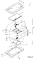
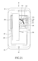
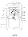
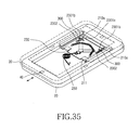
- a key input device 10 for a portable electronic device includes a main housing 20, a sliding housing 30, and at least one motion sensor 40.
- the main housing 20 may include a microphone device 21.
- the sliding housing 30 has a display unit 31 and may include a speaker device 32.
- the sliding housing 30 is adapted to face the upper surface of the main housing 20.
- the sliding housing 30 is coupled to the main housing 20 so that it can slide in the upward, downward, leftward, or rightward direction on the upper surface of the main housing 20.
- the motion sensors 40 are positioned on the main housing 20 to sense the movement of the sliding housing 30 in any of the directions, create a corresponding signal, and apply the signal to a controller (not shown). Though four motion sensors 40 are illustrated, the invention is not so limited and may include more or fewer sensors as required.
- the controller may be located inside the main housing 20 or elsewhere in the device as space or convenience require.
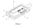
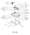
- the sliding housing 30 provides the user with functional or directional input similar to that of character keys, numeric keys, game-dedicated keys, volume keys, channel switching keys, control keys, navigation keys and the like.
- the user may provide an input regarding the movement of a cursor on the display unit 31.
- the sliding housing may be used to control a music player wherein a first sliding direction may indicate a "stop" command and another sliding direction may correlate to a "play" command.
- a first sliding direction may indicate a "stop" command and another sliding direction may correlate to a "play” command.
- the sliding housing 30 can also slide in the diagonal direction in addition to the upward, downward, leftward, and rightward directions.
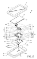
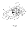
- the sliding device 100 of the key input device 10 for a portable electronic device includes a base member 110, first and second sliding members 120 and 130, a guide member 140, and first and second elastic members 150 and 160.
- the base member 110 is positioned on the main housing 20 so that the second sliding member 130 can be stacked thereon.
- the first sliding member 120 is coupled to the second housing 130 while being able to slide so that the sliding housing 30 can slide away from, that is relative to, the main housing 20 in the upward direction.
- the second sliding member 130 is coupled to the base member 110 while being able to slide so that the sliding housing 30 can slide away from the main housing 20 in the downward or leftward/rightward direction.
- the guide member 140 is positioned between the base member 110 and the second sliding member 130 so that the sliding housing 30 can slide away from the main housing 20 in the downward or leftward/rightward direction.
- the first elastic member 150 is positioned between the first and second sliding members 120 and 130 to provide an elastic force necessary to slide the sliding housing 30 away from the main housing 20 in the upward direction.
- the second elastic member 160 is positioned between the base member 110 and the second sliding member 130 to provide an elastic force necessary to slide the sliding housing 30 away from the main housing 20 in the downward or leftward/rightward direction.
- the base member 110 has at least one coupling unit 111 coupled to a coupling recess 131 c formed on the second sliding member 130 to support the second sliding member 130 so that it can slide in each direction.
- the second sliding member 130 has a guide unit 131 for guiding the sliding housing 30 so that it can slide away from the main housing 20 in the upward direction.
- the guide unit 131 includes a guide rib 131a and a guide rail 131b.
- the guide rib 131a is formed on a longitudinal side of the first sliding member 120 so that it can be coupled to the guide rail 131b while being able to slide.
- guide ribs 131a are formed on each of both longitudinal sides of the first sliding member 120.
- the guide rail 131b is formed on each of both longitudinal sides of the second sliding member 130 so that it is coupled to the guide rib 131 a while being able to slide. Furthermore, the guide rail 131b guides the sliding movement of the sliding housing 30 in the upward direction.
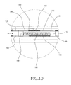
- the first elastic member 150 consists of at least one torsion spring 150 having one end 151 coupled to a fixed coupling unit formed on the first sliding member 120 and the other end 152 coupled to a protrusion formed on the second sliding member 130.
- the second elastic member 160 consists of at least one coil spring having first and second elastic movement units 170 and 180 positioned on both ends thereof so that they move in the downward or upward/downward direction and provide elastic force as the second sliding member 130 moves.
- the guide member 140 includes first and second guide movement holes 141 and 142, first and second guide movement members 143 and 144, and first and second guide holes 145 and 146.
- the first and second guide movement holes 141 and 142 are formed on the second sliding member 130 to be coupled to the first and second guide movement members 143 and 144 to guide their movement.
- the first and second guide movement members 143 and 144 are coupled into the first and second guide movement holes 141 and 142 while being able to slide so that they are coupled to the first and second elastic movement units 170 and 180 of the second elastic member 160.
- the first and second guide movement members 143 and 144 are guided along the first and second guide movement holes 141 and 142 to move the first and second elastic movement units 170 and 180 in the upward/downward direction when the second sliding member 130 moves in the downward or leftward/rightward direction.
- the first and second guide holes 145 and 146 are formed on the base member 110 so that they are coupled to coupling protrusions 193 formed on the first and second elastic movement units 170 and 180.
- the first and second guide holes 145 and 146 guide the upward/downward movement of the first and second elastic movement units 170 and 180 when the first and second guide movement units 143 and 144 move in the upward/downward direction.
- the first and second guide movement holes 141 and 142 have latching recesses 190 formed at the center so that they contact the first and second guide movement members 143 and 144 when the second sliding member 130 is at the initial location. Furthermore, when the second sliding member 130 slides downward, the first and second guide movement holes 141 and 142 travel downward together and disengage from the first guide movement member 143. In this case, the second guide movement member 144 remains engaged and travels together while maintaining contact with the latching recess 190 and moves the second elastic movement unit 180 so that the second elastic member 160 is extended/compressed.
- the first and second guide movement holes 141 and 142 have first and second slanted guide surfaces 191 and 192 formed thereon, respectively, so that they face the first and second guide movement members 143 and 144. Because the first and second guide surfaces 191 and 192 are slanted, when the second sliding member 130 slides in the leftward/rightward direction, the first and second guide movement members 143 and 144 slide in the upward/downward direction together with the first and second elastic movement units 170 and 180 in order to extend/compress the second elastic member 160.
- the sliding device 100 of the key input device 10 for a portable electronic device includes a main housing 20, a sliding housing 30, at least one motion sensor 40, a base member 110, first and second sliding members 120 and 130, a guide member 140, and first and second elastic members 150 and 160.
- the second sliding member 130 is coupled to the upper surface of the base member 110 while being able to slide in the downward or leftward/rightward direction.
- the coupling unit 111 formed on the base member 110 is coupled to the coupling recess 131c formed on the second sliding member 130.
- the guide member 140 is positioned between the base member 110 and the second sliding member 130 to guide the second sliding member 130 so that it can slide in the downward or leftward/rightward direction.
- the first sliding member 120 is coupled to the upper surface of the second sliding member 130 while being able to slide in the upward direction. More specifically, the guide rib 131a of the first sliding member 120 is coupled to the guide rail 131b of the second sliding member 130 while being able to slide.
- the first elastic member 150 is positioned between the first and second sliding members 120 and 130 to provide an elastic force necessary to slide the first sliding member 120 in the upward direction.
- the second elastic member 160 is positioned between the base member 110 and the second sliding member 130 to provide an elastic force necessary to slide the second sliding member 130 in the downward or leftward/rightward direction.
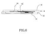
- the base member 110 is fastened to the main housing 20
- the first sliding member 120 is fastened to the sliding housing 30.
- the main housing 20 has four motion sensors 40 positioned on its upper, lower, left, and right surfaces to sense the movement of the sliding housing 30 in each direction and create a corresponding signal.
- this is merely for example and the present invention is not limited there to.
- the user when the user wants to provide a key input, for example to operate a character key, a numeric key, a game-dedicated key, a volume key, a channel switching key, a navigation key, a control key and the like, provided by the sliding housing 30, the user may slide the sliding housing 30 away from the main housing 20 in the upward direction.
- a key input for example to operate a character key, a numeric key, a game-dedicated key, a volume key, a channel switching key, a navigation key, a control key and the like
- the first sliding member 120 slides together with the sliding housing 30, and the guide rib 131a of the first sliding member 120 slides along the guide rail 131b of the second sliding member 130 in the upward direction.
- a motion sensor 40 for example the motion sensor 40 on the upper side of the main housing 20, senses the movement, creates a corresponding signal, and applies the signal to the controller (not shown).
- the controller may reside in the main housing 20.
- the controller enables the user to provide an input to operate the corresponding character key, numeric key, game-dedicated key, volume key, channel switching key, navigation key, control key and the like.
- the second guide movement member 144 in the second guide movement hole 142 moves together with the latching recess 190 formed on the second guide movement hole 142 while making contact with it. Also, the first guide movement member 143 in the first guide movement hole 141 disengages from the latching recess 190 formed on the first guide movement hole 141.
- the second guide movement member 144 moves downward together with the latching recess 190 of the second guide movement hole 142.
- the second elastic movement unit 180 also moves in the downward direction.
- the downward movement of the second elastic movement unit 180 extends the second elastic member 160.
- the first elastic movement unit 170 engages with the first guide hole 145 and stops moving further.
- the second elastic movement unit 180 moves downward along the second guide hole 146 and extends the second elastic member 160 while the first elastic movement unit 170 engages with the first guide hole 145.
- a motion sensor 40 for example the motion sensor 40 on the lower side of the main housing 20, senses the movement, creates a corresponding signal, and applies the signal to the controller (not shown). Again, the controller may be located in the main housing 20.
- the controller enables the user to provide an input to operate the corresponding character key, numeric key, game-dedicated key, volume key, channel switching key, navigation key, control key and the like.
- the second elastic member 160 is compressed again and returns to the original location.
- the second elastic movement unit 180 and the first and second sliding members 120 and 130 return to the original location.
- the sliding housing 30 and the main housing 20 stay facing each other.
- first and second sliding members 120 and 130 move together in the leftward direction.
- the first and second guide movement members 143 and 144 escape from the latching recesses 190 and are guided along the first slanted guide surface 191.
- the first and second guide movement members 143 and 144 move along the first slanted guide surface 191 in the upward/downward direction, and extend the second elastic member 160.
- One of the motion sensors 40 for example the motion sensor 40 on the left side of the main housing 20, senses the movement, creates a corresponding signal, and applies the signal to the controller (not shown). Again, the controller may be located in the main housing 20.
- the controller enables the user to provide an input to operate the corresponding character key, numeric key, game-dedicated key, volume key, channel switching key, navigation keys, control key and the like.
- the second elastic member 160 is compressed again and returns to the original location.
- the first and second guide movement members 143 and 144 return to the original location and contact the latching recesses 190 after being inserted into them.
- the second elastic movement unit 180 and the first and second sliding members 120 and 130 return to the original location together.
- the sliding housing 30 and the main housing stay facing each other.
- first and second sliding members 120 and 130 move together in the rightward direction.
- the first and second guide movement members 143 and 144 escape from the latching recesses 190 and are guided along the second slanted guide surface 192.
- the first and second guide movement members 143 and 144 move along the second slanted guide surface 192 in the upward/downward direction, and extend the second elastic member 160.
- One of the motion sensors 40 for example the motion sensor 40 on the right side of the main housing 20, senses the movement, creates a corresponding signal, and applies the signal to the controller (not shown), Again, the controller may be located in the main housing 20.
- the controller enables the user to provide an input to operate the corresponding character key, numeric key, game-dedicated key, volume key, channel switching key, navigation keys, control key and the like.
- the second elastic member 160 is compressed again and returns to the original location.
- the first and second guide movement members 143 and 144 return to the original location and contact the latching recesses 190 after being inserted into them.
- the second elastic movement unit 180 and the first and second sliding members 120 and 130 return to the original location together.
- the sliding housing 30 and the main housing stay facing each other.
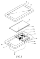
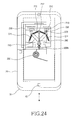
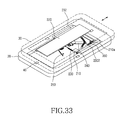
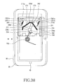
- a sliding device 200 of a key input device 10 for a portable electronic device includes a main housing 20, a sliding housing 30, at least one motion sensor 40, a base member 210, first and second sliding members 220 and 230, a link member 240, and first, second, and third elastic members 250, 260, and 270.
- the first and second sliding members 220 and 230 are stacked on the base member 210 so that the sliding housing 30 can slide away from, that is, relative to, the main housing 20 in the upward, downward, leftward, or rightward direction.
- the link member 240 is rotatably coupled to the first and second sliding members 220 and 230 so that, when the link member 240 rotates about a link axis A1, the sliding housing 30 can slide in the leftward or rightward direction.
- the first, second, and third elastic members 250, 260, and 270 are positioned between the first and second sliding members 220 and 230 to provide an elastic force necessary for sliding movements of the first and second sliding members 220 and 230.
- the base member 210 has at least one guide protrusion 211 formed on an end so that the guide protrusion 211 is coupled to a guide hole 231 formed on the second sliding member 230 to support and guide the sliding movement of the second sliding member 230 in each direction.
- One end 261 of the second elastic member 260 is fastened to an elastic fastener 212 formed on the base member 210, and the other end 262 of the second elastic member 260 is fastened to a second elastic fastener 236b formed on the second sliding member 230.
- the second elastic member 260 consists of a coil spring.
- the base member 210 has a guide movement hole 213 formed thereon, to which a guide member 235 formed on the lower surface of the second sliding member 230 is coupled.
- a rotation unit 233 formed on the second sliding member 230 is rotatably coupled to a coupling hole 243 of the link member 240, and a guide stopper 244 of the link member 240 is coupled to a rotation guide unit 234 formed on the second sliding member 230.
- First and second fastening protrusions 241 and 242 are formed on respective ends of the link member 240, and are positioned among third, fourth, and fifth elastic fasteners 236c, 236d, and 236e formed inside the second sliding member 230.
- the third elastic members 270 are fastened between the first and second fastening protrusions 241 and 242 and the third, fourth, and fifth elastic fasteners 236c, 236d, and 236e.
- the third elastic members 270 include first, second, third, and fourth coil springs 271, 272, 273, and 274.
- One end 271 a of the first coil spring 271 is fastened to one end of the third elastic fastener 236c of the second sliding member 230, and the other end 271b of the first coil spring 271 is fastened to the first fastening protrusion 241 of the link member 240.
- One end 272a of the second coil spring 272 is fastened to the first fastening protrusion 241 of the link member 240, and the other end 272b of the second coil spring 272 is fastened to the fourth elastic fastener 236d of the second sliding member 230.
- One end 273a of the third coil spring 273 is fastened to the fourth elastic fastener 236d, and the other end 273b of the third coil spring 273 is fastened to the second fastening protrusion 242 of the link member 240.
- One end 274a of the fourth coil spring 274 is fastened to the second fastening protrusion 242, and the other end 274b of the fourth coil spring 274 is fastened to the fifth elastic fastener 236e of the second sliding member 230.
- the first elastic member 250 consists of a torsion spring.
- the first sliding member 220 has guide rails 221 formed on both lateral surfaces, and the guide rails 221 are coupled to guide units 232 formed on both lateral surfaces of the second sliding member 230 while being able to slide.
- the base member 210 is fastened to the main housing 20, and the second elastic member 260 on the lower surface of the base member 210 is coupled to a space hole 20a formed on the main housing 20.
- the first sliding member 220 is fastened to the sliding housing 30.
- the main housing 20 has four motion sensors 40 on its upper, lower, left, and right surfaces, respectively, to sense the direction of movement of the sliding housing 30 and create a corresponding signal.
- this is merely for example and the present invention is not limited there to.
- the first sliding member 220 slides together with the sliding housing 30, and the guide rails 221 of the first sliding member 220 slide along the guide units 232 of the second sliding member 230 in the upward direction.
- a motion sensor 40 for example the motion sensor 40 on the upper side of the main housing 20, senses the movement, creates a corresponding signal, and applies the signal to the controller (not shown) which may be located in the main housing 20.
- the controller enables the user to provide an input to operate the corresponding character key, numeric key, game-dedicated key, volume key, channel switching key, navigation keys, control keys and the like.
- a motion sensor 40 for example the motion sensor 40 on the lower side of the main housing 20, senses the movement, creates a corresponding signal, and applies the signal to the controller (not shown).
- the controller enables the user to provide an input to operate the corresponding character key, numeric key, game-dedicated key, volume key, channel switching key, navigation key, control key and the like.
- the guide member 235 of the second sliding member 230 also moves in the downward direction while being guided along the guide movement hole 213 formed on the base member 210.
- the sliding housing 30 returns to its original location.
- the second elastic member 260 which has been extended, is compressed again, and the resulting elastic force causes the first and second sliding members 220 and 230 to slide and return to their original locations.
- the guide member 235 also moves while being guided along the guide movement hole 213.
- a motion sensor 40 for example the motion sensor 40 on the left side of the main housing 20, senses the movement, creates a corresponding signal, and applies the signal to the controller (not shown).
- the controller enables the user to provide an input to operate the corresponding character key, numeric key, game-dedicated key, volume key, channel switching key, navigation key, control key and the like.
- the link member 240 has a Y-shaped configuration, and the first and second fastening protrusions are formed on respective ends of the Y-shaped link member 240.
- the guide stopper 244 is formed on an end of the link member 240 lying opposite the ends of the link member 240, on which the first and second fastening protrusions 241 and 242 are formed, about the coupling hole 243 formed at the center of the link member 240. Therefore, the first and second fastening protrusions 241 and 242 rotate in the leftward direction, while the guide stopper 244 rotates in the rightward direction.
- the link member 240 has a Y-shaped configuration, and the first and second fastening protrusions are formed on respective ends of the link member 240 lying opposite the end of the link member 240 on which the guide stopper 244 is formed.
- the guide stopper 244 limits the rotation as it is guided and moved by the rotation guide unit 234.
- the guide member 235 of the second sliding member 230 moves in the leftward direction along the guide movement hole 213 of the base member 210.
- first and second fastening protrusions 241 and 242 when the first and second fastening protrusions 241 and 242 rotate in the leftward direction, they compress the first coil spring 271 positioned between the third elastic fastener 236c and the first fastening protrusion 241 and extend the second coil spring 272 positioned between the first fastening protrusion 241 and the fourth elastic fastener 236d.
- the third coil spring 273 between the fourth elastic fastener 236d and the second fastening protrusion 242 is compressed, while the fourth coil spring 274 between the second fastening protrusion 242 and the fifth elastic fastener 236e is extended.
- One end 261 of the second elastic member 260 is fastened to the elastic fastener 212 of the base member 210, and the other end 262 is fastened to the second elastic fastener 236b. Therefore, when the second sliding member 230 moves in the leftward direction, the second elastic fastener 236b of the second sliding member 230 moves together in the leftward direction and extends the second elastic member 260.
- the first and second sliding members 220 and 230 also return to their original locations, and the link member 240 rotates about the link axis A1 and returns to its original location.
- the first and second fastening protrusions 241 and 242 of the link member 240 are rotated from the left to the right by the third elastic members 270, which include the first, second, third, and fourth coil springs 271, 272, 273, and 274, respectively.
- the first coil spring between the third elastic fastener 236c and the first fastening protrusion 241 is extended again after it has been compressed.
- the second coil spring 272 between the first fastening protrusion 241 and the fourth elastic fastener 236d is compressed again after it has been extended.
- the third coil spring 273 between the fourth elastic fastener 236d and the second fastening protrusion 242 is extended again after it has been compressed.
- the fourth coil spring 274 between the second fastening protrusion 242 and the fifth elastic fastener 236e returns to its original location after it has been extended.
- the second elastic member 260 which has been extended, slides the second elastic fastener 236b of the second sliding member 230 from the left to the right.
- the guide stopper 244 is guided and moved by the rotation guide unit 234 until it returns to its original location.
- the guide member 235 of the second sliding member 230 also moves from the left to the right along the guide movement hole 213 of the base member 210 until it returns to its original location.
- a motion sensor 40 for example the motion sensor 40 on the right side of the main housing 20, senses the movement, creates a corresponding signal, and applies the signal to the controller (not shown).
- the controller enables the user to provide an input to operate the corresponding character key, numeric key, game-dedicated key, volume key, channel switching key, navigation key, control key and the like.
- the first and second fastening protrusions 241 and 242 rotate in the rightward direction, while the guide stopper 244 rotates in the leftward direction. That is, because the guide stopper 244 is formed on an end of the link member 240 lying opposite the ends of the link member 240 on which the first and second fastening protrusions 241 and 242 are formed, and because the coupling hole 243 is formed at the center of the link member 240, the first and second fastening protrusions 241 and 242 rotate in the rightward direction, while the guide stopper 244 rotate in the leftward direction.
- the guide stopper 244 limits the rotation of the link member 240 because it is guided and moved by the rotation guide unit 234.
- the guide member 235 of the second sliding member 230 moves in the rightward direction along the guide movement hole 213 of the base member 210.
- first and second fastening protrusions 241 and 242 rotate in the rightward direction, they extend the first coil spring 271 positioned between the third elastic fastener 236c and the first fastening protrusion 241 and compress the second coil spring 272 positioned between the first fastening protrusion 241 and the fourth elastic fastener 236d.
- the third coil spring 273 between the fourth elastic fastener 236d and the second fastening protrusion 242 is extended, while the fourth coil spring 274 between the second fastening protrusion 242 and the fifth elastic fastener 236e is compressed.
- the first and second sliding members 220 and 230 also return to their original locations, and the link member 240 rotates about the link axis A1 and returns to its original location.
- the first and second fastening protrusions 241 and 242 of the link member 240 are rotated from the right to the left by the third elastic members 270, which include the first, second, third, and fourth coil springs 271, 272, 273, and 274, respectively.
- the first coil spring 271 between the third elastic fastener 236c and the first fastening protrusion 241 is compressed again after it has been extended.
- the second coil spring 272 between the first fastening protrusion 241 and the fourth elastic fastener 236d is extended again after it has been compressed.
- the third coil spring 273 between the fourth elastic fastener 236d and the second fastening protrusion 242 is compressed again after it has been extended.
- the fourth coil spring 274 between the second fastening protrusion 242 and the fifth elastic fastener 236e is extended again after it has been compressed.
- the second elastic member 260 which has been extended, slides the second elastic fastener 236b of the second sliding member 230 from the right to the left until it returns to its original location.
- the guide stopper 244 is guided and moved by the rotation guide unit 234 until it returns to its original location.
- the guide member 235 of the second sliding member 230 also moves from the right to the left along the guide movement hole 213 of the base member 210 until it returns to its original location.
- the sliding device 200 of the key input device 10 for a portable electronic device includes a main housing 20, a sliding housing 30, at least one motion sensor 40, a base member 210, first and second sliding members 220 and 230, a link member 240, first and third elastic members 250 and 270, and at least one fourth elastic member 300.
- the first and second sliding members 220 and 230 are stacked on the base member 210 so that the sliding housing 30 can slide away from the main housing 20 in the upward, downward, leftward, or rightward direction.
- the link member 240 is rotatably coupled to the first and second sliding members 220 and 230 so that, when the link member 240 rotates about a link axis A1, the sliding housing 30 can slide in the leftward or rightward direction.
- the first and third elastic members 250 and 270 are positioned between the first and second sliding members 220 and 230 to provide elastic force necessary for sliding movements of the first and second sliding members 220 and 230.
- the fourth elastic members 300 are positioned on the second sliding member 230 to provide an additional elastic force necessary for sliding movements of the first and second sliding members 220 and 230 in the downward and leftward/rightward directions.
- the fourth elastic members 300 include at least one spring, one end 301 of which is fastened to an elastic fastener 210a formed on the base member 210, and the other end 302 of the spring 300 is fastened to an elastic fastener 2302 formed on the second sliding member 230.
- the elastic fasteners 210a of the base member 210 extend through and are coupled to at least one guide locking unit 2301 formed on the second sliding member 230.
- the guide locking units 2301 have a "+"-shaped configuration.
- the guide locking units 2301 include first locking holes 2301a adapted to move together and engage with or disengage from the elastic fasteners 210a of the base member 210, when the first and second sliding members 220 and 230 slide in the downward direction, in order to limit the sliding movements of the first and second sliding members 220 and 230 in the leftward/rightward direction.
- the guide locking units 2301 also include second locking holes 2301b positioned adjacent to the first locking holes 2301a and adapted to move together and engage with or disengage from the elastic fasteners 210a of the base member 210, when the first and second sliding members 220 and 230 slide in the leftward/rightward direction, in order to limit the sliding movements of the first and second sliding members 220 and 230 in the upward/downward direction.
- the link member 240 is rotatably coupled inside the second sliding member 230.
- a link coupling protrusion 245 extends through a coupling hole 243 formed at the center of the link member 240, as well as through a rotation unit 233 formed on the second sliding member 230, for the rotatable coupling.
- the first sliding member 220 slides together with the sliding housing 30 and the guide rib 221 of the first sliding member 220 slides along the guide unit 232 of the second sliding member 230 in the upward direction.
- a motion sensor 40 for example the motion sensor 40 on the upper side of the main housing 20, senses the movement, creates a corresponding signal, and applies the signal to the controller (not shown).
- the controller is located in the main housing 20.
- the controller enables the user to provide an input to operate the corresponding character key, numeric key, game-dedicated key, volume key, channel switching key, navigation key, control key and the like.
- a motion sensor 40 for example the motion sensor 40 on the lower side of the main housing 20 senses the movement, creates a corresponding signal, and applies the signal to the controller (not shown).
- the controller enables the user to provide an input to operate the corresponding character key, numeric key, game-dedicated key, volume key, channel switching key, navigation key, control key and the like.
- the first and second sliding members 220 and 230 slide together, and the elastic fasteners 2302 of the second sliding member 230 also move.
- the fourth elastic members 300 fastened to the elastic fasteners 2302 are then extended.
- the guide locking units 2301 of the second sliding member 230 also move in the downward direction, and are coupled to the elastic fasteners 210a formed on the base member 210.
- the elastic fasteners 210a of the base member 210 are coupled to the first locking holes 2301a of the guide locking units 2301, which then limit the sliding movements of the first and second sliding members 220 and 230 in the leftward/rightward direction.
- the sliding housing 30 returns to its original location.
- the first and second sliding members 220 and 230 also slide and return to their original locations by means of the elastic force from the fourth elastic members 300 which are compressed after having been extended.
- the first locking holes 2301a of the guide locking units 2301 also move together and disengage from the elastic fasteners 210a of the base member 210. As a result, the guide locking units 2301 are unlocked from the base member 210.
- a motion sensor 40 for example the motion sensor 40 on the left side of the main housing 20, senses the movement, creates a corresponding signal, and applies the signal to the controller (not shown).
- the controller enables the user to provide an input to operate the corresponding character key, numeric key, game-dedicated key, volume key, channel switching key, navigation key, control key and the like.
- the guide stopper 244 is formed on an end of the link member 240 lying opposite the ends of the link member 240, on which the first and second fastening protrusions 241 and 242 are formed, about the coupling hole 243 formed at the center of the link member 240. Therefore, the first and second fastening protrusions 241 and 242 rotate in the leftward direction, while the guide stopper 244 rotates in the rightward direction.
- the link member 240 has a Y-shaped configuration, and the first and second fastening protrusions are formed on respective ends of the link member 240 lying opposite the end of the link member 240 on which the guide stopper 244 is formed.
- the guide stopper 244 limits the rotation as it is guided and moved by the rotation guide unit 234.
- first and second fastening protrusions 241 and 242 when the first and second fastening protrusions 241 and 242 rotate in the leftward direction, they compress the first coil spring 271 positioned between the third elastic fastener 236c and the first fastening protrusion 241 and extend the second coil spring 272 positioned between the first fastening protrusion 241 and the fourth elastic fastener 236d.
- the third coil spring 273 between the fourth elastic fastener 236d and the second fastening protrusion 242 is compressed, while the fourth coil spring 274 between the second fastening protrusion 242 and the fifth elastic fastener 236e is extended.
- one end 301 of the fourth elastic member 300 is fastened to the elastic fastener 210a of the base member 210, and the other end 302 is fastened to the elastic fastener 2302 of the second sliding member 230 so that, when the second sliding member 230 moves in the leftward direction, the elastic fastener 2302 of the second sliding member 230 moves together in the leftward direction and extends the fourth elastic member 300.
- the guide locking unit 2301 of the second sliding member 230 also moves in the leftward direction, and the second locking unit 2301b of the guide locking unit 2301 moves together to be coupled to the elastic fastener 210a of the base member 210.
- the guide locking unit 2301 is locked onto the base member 210 and limits the sliding movements of the first and second sliding members 220 and 230 in the upward/downward direction.
- the first and second sliding members 220 and 230 also return to their original locations, and the link member 240 rotates about the link axis A1 until it returns to its original location.
- the first and second fastening protrusions 241 and 242 of the link member 240 are rotated from the left to the right by the third elastic members 270, which include the first, second, third, and fourth coil springs 271, 272, 273, and 274, respectively.
- the first coil spring between the third elastic fastener 236c and the first fastening protrusion 241 is extended again after it has been compressed.
- the second coil spring 272 between the first fastening protrusion 241 and the fourth elastic fastener 236d is compressed again after it has been extended.
- the third coil spring 273 between the fourth elastic fastener 236d and the second fastening protrusion 242 is extended again after it has been compressed.
- the fourth coil spring 274 between the second fastening protrusion 242 and the fifth elastic fastener 236e returns to its original location after it has been extended.
- the fourth elastic members 300 which have been extended, are compressed and slide the elastic fasteners 2302 of the second sliding member 230 from the left to the right.
- the guide locking units 2301 also move from the left to the right, and the second locking holes 2301b of the guide locking units 2301 disengage from the elastic fasteners 210a of the base member 210 and return to their original locations. As a result, the guide locking units 2301 are unlocked from the base member 210.
- a motion sensor 40 for example the motion sensor 40 on the right side of the main housing 20, senses the movement, creates a corresponding signal, and applies the signal to the controller (not shown).
- the controller enables the user to provide an input to operate the corresponding character key, numeric key, game-dedicated key, volume key, channel switching key, navigation key, control key and the like.
- the first and second fastening protrusions 241 and 242 rotate in the rightward direction, while the guide stopper 244 rotates in the leftward direction, because the guide stopper 244 is formed on an end of the link member 240 lying opposite the ends of the link member 240, on which the first and second fastening protrusions 241 and 242 are formed, respectively, about the coupling hole 243 formed at the center of the link member 240.
- the guide stopper 244 limits the rotation as it is guided and moved by the rotation guide unit 234.
- first and second fastening protrusions 241 and 242 rotate in the rightward direction, they extend the first coil spring 271 positioned between the third elastic fastener 236c and the first fastening protrusion 241 and compress the second coil spring 272 positioned between the first fastening protrusion 241 and the fourth elastic fastener 236d.
- the third coil spring 273 between the fourth elastic fastener 236d and the second fastening protrusion 242 is extended, while the fourth coil spring 274 between the second fastening protrusion 242 and the fifth elastic fastener 236e is compressed.
- the guide locking units 2301 of the second sliding member 230 move together in the rightward direction, and the second locking units 2301b of the guide locking units 2301 move together to be coupled to the elastic fasteners 210a of the base member 210.
- the guide locking units 2301 are locked onto the base member 210 and limit the sliding movements of the first and second sliding members 220 and 230 in the upward/downward direction.
- the first and second sliding members 220 and 230 also return to their original locations, and the link member 240 rotates about the link axis A1 and returns to its original location.
- the first and second fastening protrusions 241 and 242 of the link member 240 are rotated from the right to the left by the third elastic members 270, which include the first, second, third, and fourth coil springs 271, 272, 273, and 274.
- the first coil spring 271 between the third elastic fastener 236c and the first fastening protrusion 241 is compressed again after it has been extended.
- the second coil spring 272 between the first fastening protrusion 241 and the fourth elastic fastener 236d is extended again after it has been compressed.
- the third coil spring 273 between the fourth elastic fastener 236d and the second fastening protrusion 242 is compressed again after it has been extended.
- the fourth coil spring 274 between the second fastening protrusion 242 and the fifth elastic fastener 236e is extended again after it has been compressed.
- the fourth elastic members 300 which have been extended, are compressed and slide the elastic fasteners 2302 of the second sliding member 230 from the right to the left.
- the guide locking units 2301 also move from the right to the left, and the second locking holes 2301b of the guide locking units 2301 disengage from the elastic fasteners 210a of the base member 210 and return to their original locations. As a result, the guide locking units 2301 are unlocked from the base member 210.
- the sliding device of a key input device for a portable electronic device is advantageous in that the sliding housing equipped with a display unit is adapted to slide in four directions and is used as a key input device instead of the existing direction and navigation keys so that key inputs can be made easily and that the terminal can be compact and slim.
- the present invention is applicable to every type of portable terminal.
Landscapes
- Engineering & Computer Science (AREA)
- Signal Processing (AREA)
- General Engineering & Computer Science (AREA)
- Theoretical Computer Science (AREA)
- Human Computer Interaction (AREA)
- Physics & Mathematics (AREA)
- General Physics & Mathematics (AREA)
- Telephone Set Structure (AREA)
Applications Claiming Priority (2)
| Application Number | Priority Date | Filing Date | Title |
|---|---|---|---|
| KR20070061550 | 2007-06-22 | ||
| KR1020070129062A KR20080112905A (ko) | 2007-06-22 | 2007-12-12 | 휴대용 전자 장치 |
Publications (2)
| Publication Number | Publication Date |
|---|---|
| EP2007116A2 true EP2007116A2 (fr) | 2008-12-24 |
| EP2007116A3 EP2007116A3 (fr) | 2011-09-14 |
Family
ID=39773009
Family Applications (1)
| Application Number | Title | Priority Date | Filing Date |
|---|---|---|---|
| EP08158361A Withdrawn EP2007116A3 (fr) | 2007-06-22 | 2008-06-16 | Utilisation du mouvement des boîtiers coulissants comme entrée dans un telephone portable |
Country Status (2)
| Country | Link |
|---|---|
| US (1) | US7801580B2 (fr) |
| EP (1) | EP2007116A3 (fr) |
Cited By (2)
| Publication number | Priority date | Publication date | Assignee | Title |
|---|---|---|---|---|
| WO2010115476A1 (fr) * | 2009-04-09 | 2010-10-14 | Sony Ericsson Mobile Communications Ab | Système de dispositif mobile coulissant omnidirectionnel |
| EP2317735A3 (fr) * | 2009-10-28 | 2013-02-27 | Lg Electronics Inc. | Terminal mobile |
Families Citing this family (12)
| Publication number | Priority date | Publication date | Assignee | Title |
|---|---|---|---|---|
| TWI338491B (en) * | 2007-12-06 | 2011-03-01 | Htc Corp | Electronic device and sliding mechanism thereof |
| US7716786B2 (en) * | 2007-12-17 | 2010-05-18 | Shin Zu Shing Co., Ltd. | Slide hinge |
| US7809415B2 (en) * | 2008-09-08 | 2010-10-05 | Chin-Fu Horng | Coupling structure of sliding type |
| CN101764859B (zh) * | 2008-12-23 | 2013-06-05 | 鸿富锦精密工业(深圳)有限公司 | 电子装置 |
| US8213181B2 (en) * | 2009-06-29 | 2012-07-03 | Nokia Corporation | Apparatus for a movable chassis configuration |
| CN201797673U (zh) * | 2010-08-24 | 2011-04-13 | 新日兴股份有限公司 | 滑盖式枢纽器及滑盖式可携装置 |
| CN102548298A (zh) * | 2010-12-31 | 2012-07-04 | 深圳富泰宏精密工业有限公司 | 滑动模组及具有该滑动模组的电子装置 |
| TWI502313B (zh) * | 2012-06-08 | 2015-10-01 | Wistron Corp | 用來支撐顯示模組於支撐座上之支撐機構與可攜式電子裝置 |
| CA154443S (en) * | 2013-07-04 | 2014-10-27 | Lg Electronics Inc | Mobile phone |
| USD753640S1 (en) * | 2013-07-04 | 2016-04-12 | Lg Electronics Inc. | Mobile phone |
| DE102014204292A1 (de) * | 2014-03-10 | 2015-09-10 | Bayerische Motoren Werke Aktiengesellschaft | Verfahren zum Herstellen einer Schraub-Klebverbindung unter Verwendung einer fließlochformenden Schraube, sowie hiernach hergestellter Bauteilverbund |
| KR102237598B1 (ko) * | 2016-08-31 | 2021-04-07 | 삼성전자주식회사 | 디스플레이 장치 |
Citations (6)
| Publication number | Priority date | Publication date | Assignee | Title |
|---|---|---|---|---|
| WO2003054672A1 (fr) | 2001-12-20 | 2003-07-03 | Nokia Corporation | Terminal mobile a couvercle fonctionnel repliable |
| US20050059438A1 (en) | 2003-09-12 | 2005-03-17 | Motorola, Inc. | Communication device having multiple keypads |
| US20050070348A1 (en) | 2003-09-29 | 2005-03-31 | Inventec Appliances Corp. | Hand-held communication electronic apparatus having two slidable keypads |
| EP1631043A1 (fr) | 2004-08-24 | 2006-03-01 | Samsung Electronics Co., Ltd. | Appareil de communication portable du type coulissant en deux directions et dispositif coulissant pour le même |
| US20060061943A1 (en) * | 2004-09-20 | 2006-03-23 | Santos Theodore R | Devices and methods for controlling relative movement between layers of an electronic device |
| EP1786181A2 (fr) * | 2005-11-11 | 2007-05-16 | Samsung Electronics Co., Ltd. | Téléphone portable comportant un module coulissant pour faire glisser des boîtiers dans deux directions différentes |
Family Cites Families (14)
| Publication number | Priority date | Publication date | Assignee | Title |
|---|---|---|---|---|
| GB2310568B (en) * | 1996-02-26 | 1999-10-20 | Nokia Mobile Phones Ltd | Radio telephone |
| KR100704031B1 (ko) * | 2004-04-29 | 2007-04-04 | 삼성전자주식회사 | 이중 슬라이딩 타입 휴대용 통신 장치 |
| US7671836B2 (en) * | 2005-01-03 | 2010-03-02 | Nokia Corporation | Cell phone with shiftable keypad |
| TWI260904B (en) * | 2005-03-14 | 2006-08-21 | Benq Corp | Two ways slider-type electronic device and sliding assembly |
| US20070142101A1 (en) * | 2005-08-23 | 2007-06-21 | Sudhir Seshagiri | Mobile electronic device having a rotatable keypad |
| KR100810263B1 (ko) * | 2005-10-11 | 2008-03-07 | 삼성전자주식회사 | 휴대용 단말기의 키패드, 슬라이딩 모듈 및 그의 연성 회로 |
| US7529081B2 (en) * | 2006-01-05 | 2009-05-05 | Motorola, Inc. | Electronic device and slide mechanism |
| US7720446B2 (en) * | 2006-05-16 | 2010-05-18 | Nokia Corporation | Multi-position device |
| EP1871076A1 (fr) * | 2006-06-19 | 2007-12-26 | Samsung Electronics Co., Ltd. | Module coulissant pour téléphone mobile |
| JP5192668B2 (ja) * | 2006-07-28 | 2013-05-08 | シャープ株式会社 | 携帯型端末 |
| USD563936S1 (en) * | 2006-12-14 | 2008-03-11 | Samsung Electronics Co., Ltd. | Portable phone |
| CN101237478B (zh) * | 2007-02-02 | 2012-03-07 | 深圳富泰宏精密工业有限公司 | 便携式电子装置 |
| US7970444B2 (en) * | 2007-02-28 | 2011-06-28 | Sony Ericsson Mobile Communications Ab | Pivoting mobile terminal |
| KR100856238B1 (ko) * | 2007-03-20 | 2008-09-03 | 삼성전자주식회사 | 슬라이딩형 휴대용 단말기 |
-
2008
- 2008-06-16 EP EP08158361A patent/EP2007116A3/fr not_active Withdrawn
- 2008-06-23 US US12/144,088 patent/US7801580B2/en not_active Expired - Fee Related
Patent Citations (6)
| Publication number | Priority date | Publication date | Assignee | Title |
|---|---|---|---|---|
| WO2003054672A1 (fr) | 2001-12-20 | 2003-07-03 | Nokia Corporation | Terminal mobile a couvercle fonctionnel repliable |
| US20050059438A1 (en) | 2003-09-12 | 2005-03-17 | Motorola, Inc. | Communication device having multiple keypads |
| US20050070348A1 (en) | 2003-09-29 | 2005-03-31 | Inventec Appliances Corp. | Hand-held communication electronic apparatus having two slidable keypads |
| EP1631043A1 (fr) | 2004-08-24 | 2006-03-01 | Samsung Electronics Co., Ltd. | Appareil de communication portable du type coulissant en deux directions et dispositif coulissant pour le même |
| US20060061943A1 (en) * | 2004-09-20 | 2006-03-23 | Santos Theodore R | Devices and methods for controlling relative movement between layers of an electronic device |
| EP1786181A2 (fr) * | 2005-11-11 | 2007-05-16 | Samsung Electronics Co., Ltd. | Téléphone portable comportant un module coulissant pour faire glisser des boîtiers dans deux directions différentes |
Cited By (2)
| Publication number | Priority date | Publication date | Assignee | Title |
|---|---|---|---|---|
| WO2010115476A1 (fr) * | 2009-04-09 | 2010-10-14 | Sony Ericsson Mobile Communications Ab | Système de dispositif mobile coulissant omnidirectionnel |
| EP2317735A3 (fr) * | 2009-10-28 | 2013-02-27 | Lg Electronics Inc. | Terminal mobile |
Also Published As
| Publication number | Publication date |
|---|---|
| US7801580B2 (en) | 2010-09-21 |
| US20090027837A1 (en) | 2009-01-29 |
| EP2007116A3 (fr) | 2011-09-14 |
Similar Documents
| Publication | Publication Date | Title |
|---|---|---|
| EP2007116A2 (fr) | Utilisation du mouvement des boîtiers coulissants comme entrée dans un telephone portable | |
| EP1775596B1 (fr) | Clavier pour un terminal portable de type coulissant | |
| EP2134065B1 (fr) | Terminal portable | |
| US7991442B2 (en) | Multiple opening and closing type mobile communication terminal | |
| US8466876B2 (en) | Terminal | |
| EP1898605B1 (fr) | Dispositif d'entrée à touches pour appareil de communications portable et module coulissant correspondant | |
| KR100993095B1 (ko) | 폴더식 휴대기기 | |
| US8014845B2 (en) | Information terminal device | |
| EP1594290B1 (fr) | Terminal doublement pliable | |
| US8108016B2 (en) | Portable communication device having a dual sliding flip hinge assembly | |
| US7853301B2 (en) | Sliding module for double sliding-type portable communication terminal | |
| US8275121B2 (en) | Portable communication device having a combined slider and flip hinge assembly | |
| KR100800827B1 (ko) | 플립 업 타입 이동 통신 단말기 | |
| US8107229B2 (en) | Portable communication device having a printed circuit board slider hinge assembly | |
| JP4216887B1 (ja) | 折り畳み式携帯端末装置 | |
| CN101330533A (zh) | 便携式电子装置 | |
| KR100803457B1 (ko) | 이중 슬라이딩 타입 휴대용 통신 장치의 슬라이딩 모듈 | |
| KR20070054433A (ko) | 슬라이드형 단말기 | |
| KR20090070586A (ko) | 휴대용 전자 장치 | |
| KR20060120847A (ko) | 교차 슬라이딩 방식의 개인휴대단말기 |
Legal Events
| Date | Code | Title | Description |
|---|---|---|---|
| PUAI | Public reference made under article 153(3) epc to a published international application that has entered the european phase |
Free format text: ORIGINAL CODE: 0009012 |
|
| 17P | Request for examination filed |
Effective date: 20080616 |
|
| AK | Designated contracting states |
Kind code of ref document: A2 Designated state(s): AT BE BG CH CY CZ DE DK EE ES FI FR GB GR HR HU IE IS IT LI LT LU LV MC MT NL NO PL PT RO SE SI SK TR |
|
| AX | Request for extension of the european patent |
Extension state: AL BA MK RS |
|
| PUAL | Search report despatched |
Free format text: ORIGINAL CODE: 0009013 |
|
| AK | Designated contracting states |
Kind code of ref document: A3 Designated state(s): AT BE BG CH CY CZ DE DK EE ES FI FR GB GR HR HU IE IS IT LI LT LU LV MC MT NL NO PL PT RO SE SI SK TR |
|
| AX | Request for extension of the european patent |
Extension state: AL BA MK RS |
|
| RIC1 | Information provided on ipc code assigned before grant |
Ipc: G06F 3/033 20060101ALI20110805BHEP Ipc: H04M 1/02 20060101AFI20110805BHEP |
|
| AKX | Designation fees paid |
Designated state(s): DE FR GB |
|
| 17Q | First examination report despatched |
Effective date: 20120703 |
|
| RAP1 | Party data changed (applicant data changed or rights of an application transferred) |
Owner name: SAMSUNG ELECTRONICS CO., LTD. |
|
| STAA | Information on the status of an ep patent application or granted ep patent |
Free format text: STATUS: THE APPLICATION IS DEEMED TO BE WITHDRAWN |
|
| 18D | Application deemed to be withdrawn |
Effective date: 20150114 |