EP2007108B1 - Verbinder zur Filterung von Netzwerkverkehr - Google Patents
Verbinder zur Filterung von Netzwerkverkehr Download PDFInfo
- Publication number
- EP2007108B1 EP2007108B1 EP08103169A EP08103169A EP2007108B1 EP 2007108 B1 EP2007108 B1 EP 2007108B1 EP 08103169 A EP08103169 A EP 08103169A EP 08103169 A EP08103169 A EP 08103169A EP 2007108 B1 EP2007108 B1 EP 2007108B1
- Authority
- EP
- European Patent Office
- Prior art keywords
- network
- signal
- preset
- network apparatus
- connector
- Prior art date
- Legal status (The legal status is an assumption and is not a legal conclusion. Google has not performed a legal analysis and makes no representation as to the accuracy of the status listed.)
- Ceased
Links
Images


Classifications
-
- H—ELECTRICITY
- H01—ELECTRIC ELEMENTS
- H01R—ELECTRICALLY-CONDUCTIVE CONNECTIONS; STRUCTURAL ASSOCIATIONS OF A PLURALITY OF MUTUALLY-INSULATED ELECTRICAL CONNECTING ELEMENTS; COUPLING DEVICES; CURRENT COLLECTORS
- H01R31/00—Coupling parts supported only by co-operation with counterpart
- H01R31/06—Intermediate parts for linking two coupling parts, e.g. adapter
-
- H—ELECTRICITY
- H04—ELECTRIC COMMUNICATION TECHNIQUE
- H04L—TRANSMISSION OF DIGITAL INFORMATION, e.g. TELEGRAPHIC COMMUNICATION
- H04L63/00—Network architectures or network communication protocols for network security
- H04L63/02—Network architectures or network communication protocols for network security for separating internal from external traffic, e.g. firewalls
- H04L63/0227—Filtering policies
- H04L63/0236—Filtering by address, protocol, port number or service, e.g. IP-address or URL
-
- H—ELECTRICITY
- H01—ELECTRIC ELEMENTS
- H01R—ELECTRICALLY-CONDUCTIVE CONNECTIONS; STRUCTURAL ASSOCIATIONS OF A PLURALITY OF MUTUALLY-INSULATED ELECTRICAL CONNECTING ELEMENTS; COUPLING DEVICES; CURRENT COLLECTORS
- H01R31/00—Coupling parts supported only by co-operation with counterpart
- H01R31/005—Intermediate parts for distributing signals
-
- H—ELECTRICITY
- H01—ELECTRIC ELEMENTS
- H01R—ELECTRICALLY-CONDUCTIVE CONNECTIONS; STRUCTURAL ASSOCIATIONS OF A PLURALITY OF MUTUALLY-INSULATED ELECTRICAL CONNECTING ELEMENTS; COUPLING DEVICES; CURRENT COLLECTORS
- H01R31/00—Coupling parts supported only by co-operation with counterpart
- H01R31/06—Intermediate parts for linking two coupling parts, e.g. adapter
- H01R31/065—Intermediate parts for linking two coupling parts, e.g. adapter with built-in electric apparatus
-
- H—ELECTRICITY
- H04—ELECTRIC COMMUNICATION TECHNIQUE
- H04L—TRANSMISSION OF DIGITAL INFORMATION, e.g. TELEGRAPHIC COMMUNICATION
- H04L63/00—Network architectures or network communication protocols for network security
- H04L63/02—Network architectures or network communication protocols for network security for separating internal from external traffic, e.g. firewalls
- H04L63/0272—Virtual private networks
-
- H—ELECTRICITY
- H04—ELECTRIC COMMUNICATION TECHNIQUE
- H04L—TRANSMISSION OF DIGITAL INFORMATION, e.g. TELEGRAPHIC COMMUNICATION
- H04L63/00—Network architectures or network communication protocols for network security
- H04L63/16—Implementing security features at a particular protocol layer
- H04L63/162—Implementing security features at a particular protocol layer at the data link layer
Definitions
- the present invention relates to a connector and a communication method thereof, and more particularly, to a connector which is capable of being connected to apparatuses forming a network, and a communication method thereof.
- a connector such as RJ-45 is connected to a local area network (LAN) card or a hub to allow data exchange between network apparatuses.
- network apparatuses may include a computer, a printer, a TV, and other network devices known in the art, in which a relay such as a hub, a modem or the like and a network device such as a LAN card are installed.
- An example of a network system is a Transmission Control Protocol/Internet Protocol (TCP/IP) Ethernet system in which apparatuses included in a network form a sub-network.
- TCP/IP Transmission Control Protocol/Internet Protocol
- apparatuses which belong to the same sub-network may have weak security.
- a home having a home network it is not difficult to access apparatuses forming the home network from outside the network.
- access may be made from an apparatus of a home to an apparatus of another home.
- access may be made between apparatuses in different departments, the apparatuses forming the same sub-network.
- some apparatuses which belong to a sub-network may form a particular network, separately from other apparatuses of the same sub-network, for security or according to a user's need.
- the particular network may include apparatuses which belong to each home in an apartment, or include apparatuses which belong to each department in an office.
- IP Internet Protocol
- MAC media access control
- WO 99/21340 discloses a processor which determines if a source IP of a packet matches a stored IP address. Data is either discarded or forwarded depending on the processor configuration.
- WO 2005/074227 discloses a dongle having a fingerprint scanner and a card reader, for added security.
- United States Patent Application No. US 2006/274771 discloses a device for extracting MAC address and a piece of VLAN tag information from a reception packet and storing the extracted data in an association table.
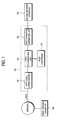
- Figure 1 is a block diagram showing a configuration of a connector according to an embodiment of the present invention
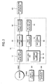
- Figure 2 is a block diagram showing a configuration of a connector according to another embodiment of the present invention.
- a connector according to an embodiment of the present invention is connected to a network device of a network apparatus and transmits a signal, which is received from a different network apparatus, to the network apparatus to which the connector is connected.
- the connector includes one end coupled to a LAN card of a computer and the other end coupled to an RJ-45 plug to which an unshielded twisted pair (UTP) cable is connected, and it is determined based on preset information whether to pass or intercept signals that are transmitted / received through both ends of the connector.
- UTP unshielded twisted pair
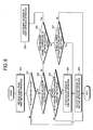
- the connector is differentiated into a first connector 100 connected to a second network apparatus 400 and a second connector 200 connected to a first network apparatus 300 although the first and second connectors have the same configuration.
- the first connector 100 includes a first cable connecting unit 110, a first apparatus connecting unit 120, a first communicating unit 130 and a first controller 140.
- the first cable connecting unit 110 is connected with a cable via which a signal is transmitted from the first network apparatus 300. Specifically, the first cable connecting unit 110 is connected to a plug of the cable that connects a network to the first cable connecting unit 110.
- the first cable connecting unit 110 may be connected with an RJ-45 plug of a UTP cable.
- the first apparatus connecting unit 120 is connected to the second network apparatus 400. Specifically, the first apparatus connecting unit 120 is connected to a network device of the second network apparatus 400. For example, the first apparatus connecting unit 120 may be connected to an RJ-45 port of a LAN card.
- the first communicating unit 130 communicates with the first and second network apparatuses 300 and 400. The first communicating unit 130 delivers or intercepts the signal, which is received from the first network apparatus 300, to the second network apparatus 400 under control of the first controller 140. In addition, the first communicating unit 130 may generate a new signal or combine signals under control of the first controller 140.
- the first controller 140 controls the first communicating unit 130 to deliver the signal to the second network apparatus 400.
- the signal may include all signals for communication in a network of a TCP/IP Ethernet system.
- the signal also includes identification information of the first network apparatus 300.
- the identification information includes a MAC address, an IP address and so on.
- the signal may include a network identification (ID) for network setting. Accordingly, the first controller 140 may discriminate an apparatus, which transmits the signal, among a plurality of apparatuses connected to the network based on the identification information included in the signal.
- the first controller 140 passes the signal, which is received via the first cable connecting unit 110, to the first apparatus connecting unit 120, and, if the identification information is not the pre-stored information, controls the first communicating unit 130 to intercept the signal.
- the first connector 100 may further include a first ID input unit 150, a first storing unit 160 and a first function selecting unit 170.
- the first ID input unit 150 receives a preset network ID from a user.
- the preset network ID may be binary data composed of a plurality of bits.
- the first ID input unit 150 may include a switching unit 151 which may set each bit of the plurality of bits.
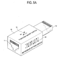
- the first connector 100 may be embodied in the form of a dongle 10.
- the dongle 10 includes a terminal 11 for connection of an RJ-45 plug on one side and a terminal 12 for connection of a LAN card on the other side.
- the dongle 10 includes switches 14 for network ID setting. If a network ID has an 8 bit binary data format, the dongle 10 may be provided with 8 switches 14 for setting respective bits.
- the first ID input unit 150 may be embodied by a numeric pad 24 for network ID setting, as shown in Figure 5B . If the network ID of the first network apparatus 300 is a preset network ID, the first controller 140 determines the first network apparatus 300 to be a preset apparatus. Specifically, if the first controller 140 receives a signal including a network ID via the first cable connecting unit 110, the first controller 140 compares the network ID of the received signal with a network ID inputted through the first ID input unit 150 to determine whether or not the network IDs match, and, based on the determination, controls the first communicating unit 130 to deliver only a signal, which is transmitted from an apparatus having the same network ID, to the second network apparatus 400.
- a signal including the network ID may be a network start signal having a predetermined format.
- the network start signal is constituted by a plurality of fields, each of which includes information such as an instruction code, an IP address, a protocol, a port, a network ID, a MAC address, cyclic redundancy check (CRC) or the like.
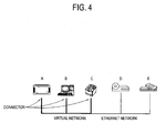
- a user may connect the connector to network apparatuses A, B and C, for which the user desires to set security, of a plurality of network apparatuses A, B, C, D and E. Then, the user inputs a network ID through the ID input unit of the connector.
- the network apparatuses A, B and C to which the connector inputted the same network ID is connected can communicate with each other, however, network apparatuses D and E to which the connector is not connected can not access the network apparatuses A, B and C to which the connector is connected. Accordingly, the user has to input the same network ID to the connector connected to the network apparatuses A, B and C for security setting.
- the network ID is generated and processed in the connector.
- a plurality of MAC addresses may be stored in the first storing unit 160 which may be embodied by a nonvolatile memory.
- the first controller 140 stores a MAC address of the first network apparatus 300 having the preset network ID in the first storing unit 160. That is, the first controller 140 stores the MAC address of a network apparatus having the same network ID in the first storing unit 160. More specifically, if the first controller 140 receives a signal including a network ID via the first cable connecting unit 110, the first controller 140 compares the network ID included in the received signal with a network ID inputted through the first ID input unit 150 to determine whether or not both network IDs match, and, if it is determined that both network IDs match, stores the MAC address of the first network apparatus 300, which transmits the signal, in the first storing unit 160.
- the first controller 140 confirms the MAC address of the first network apparatus 300 for the signal transmitted from the first network apparatus 300 having the preset network ID, and, if the MAC address is a preset MAC address, the first controller 140 determines the first network apparatus 300 to be a preset apparatus. Specifically, if it is determined that the network ID of the first network apparatus 300 is the preset network ID, the first controller 140 stores the MAC address of the first network apparatus 300 in the storing unit 160, and, if the MAC address of the first network apparatus 300 is one of a plurality of MAC addresses stored in the storing unit 160, controls the first communicating unit 130 to deliver the signal, which is received from the first network apparatus 300, to the second network apparatus 400.
- the first controller 140 may delete the MAC address of the first network apparatus 300 that transmits the signal based on information of the signal received through the first cable connecting unit 110. For example, if the first controller 140 receives a network secession signal having a predetermined format from the first network apparatus 300, the first controller 140 deletes the MAC address of the first network apparatus 300 from the storing unit 160.
- the network secession signal may be constituted by a plurality of fields, each of which includes information such as an instruction code, an IP address, a protocol, a port, a network ID, a MAC address, cyclic redundancy check (CRC) or the like.
- the first controller 140 may control the first communicating unit 130 to deliver the signal to the second network apparatus 400 according to the MAC address of the preset apparatus. For example, the first controller 140 detects and stores a MAC address of an apparatus, which is the destination of the signal, from the signal transmitted from the second network apparatus 400. Thereafter, although the first network apparatus 300 has a first network ID that does not match a second network ID of the second network apparatus 400 or no first network ID, the first network apparatus 300 can communicate with the second network apparatus 400.
- the first function selecting unit 170 receives an ON/OFF selection signal from a user. As shown in Figure 5A , the first function selecting unit 170 may be embodied by an ON/OFF switch 13. As an alternative embodiment, the first functional selecting unit 170 may be embodied by an ON/OFF button 23, as shown in Figure 5B .
- the first controller 140 may control the first communicating unit 130 to deliver a signal, which is transmitted from a preset apparatus, to the second network apparatus 400 according to an input from the first function selecting unit 170. For example, the first controller 140 generates a network start signal upon receiving an ON signal from the first function selecting unit 170, and generates a network secession signal upon receiving an OFF signal from the first function selecting unit 170. The first controller 140 controls the first communicating unit 130 to deliver the generated network start signal and network secession signal to the second network apparatus 400.
- the second connector 200 includes a second cable connecting unit 210, a second apparatus connecting unit 220, a second communicating unit 230 and a second controller 240.
- the second connector 200 may further include a second ID input unit 250, a second storing unit 260 and a second function selecting unit 270.
- the second cable connecting unit 210 is connected to a cable via which a signal is transmitted from and received by the first network apparatus 300.
- the second apparatus connecting unit 220 is connected to the first network apparatus 300.
- the second communicating unit 230 communicates with the first network apparatus 300 and the second network apparatus 400.
- the second controller 240 controls the second communicating unit 230 to deliver a preset network ID to the second network apparatus 400.
- the second connector 200 connected to the first network apparatus 300 transmits a network start signal for network setting or a network secession signal to the first connector 100 connected to the second network apparatus 400.
- the second ID input unit 250 receives the preset network ID from a user.
- the network ID may be binary data of a plurality of bits.
- the second ID input unit 250 may include a switching unit which may set each bit of the plurality of bits.
- the second function selecting unit 270 receives an ON/OFF selection signal from a user.
- the second controller 240 controls the second communicating unit 230 to deliver the preset network ID to the second network apparatus 400 according to an input from the second function selecting unit 270. For example, if the input from the second function selecting unit 270 is an ON signal, or if the second connector 200 receives an initial signal from the first network apparatus 300, the second connector 200 transmits a network start signal to all apparatuses connected to a network. In addition, if the input from the second function selecting unit 270 is an OFF signal, the second connector 200 transmits a network secession signal to all apparatuses connected to the network. Each of the network start signal and the network secession signal includes a network ID of the second connector 200 and a MAC address of the first network apparatus 300.
- the first connector 100 Upon receiving the network start signal, the first connector 100 determines whether or not a received network ID matches a network ID of the first connector 100, and, if it is determined that the received network ID matches the network ID of the first connector 100, stores the received MAC address. Thereafter, if the MAC address of the received signal matches the pre-stored one, the first connector 100 passes the received signal. Upon receiving the network secession signal, the first connector 100 deletes the MAC address of the received network secession signal from a plurality of pre-stored MAC addresses and intercepts the received signal.
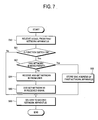
- the first connector 100 receives a signal from the first network apparatus 300 at operation S10.
- the first connector 100 determines whether or not the first network apparatus 300 that transmits the signal is a preset apparatus at operation S20. If it is determined that the first network apparatus 300 is the preset apparatus, the first connector 100 delivers the signal to the second network apparatus 400 at operation S30.
- the first connector 100 receives the signal from the first network apparatus 300 via the first cable connecting unit 110 at the operation S10.
- the operation S20 may include operations S21, S22, S23, S24, S25, S26 and S27.
- the first controller 140 determines whether or not a function switch of the first function switching unit 170 is in an ON state at operation S21. If it is determined at the operation S21 that the function switch is in the ON state, the first controller 140 determines whether or not a network ID is in the received signal at operation S22. If it is determined at the operation S22 that the network ID is in the received signal, the first controller 140 determines whether the network ID received from the first network apparatus 300 is a preset network ID at operation S23. If it is determined at the operation S23 that the received network ID is the preset network ID, the first controller 140 stores a MAC address of the first network apparatus 300 in the first storing unit 160 at operation S24.
- the first controller 140 controls the first communicating unit 130 to deliver the signal, which is received from the first network apparatus 300, to the second network apparatus 400 at operation S30.
- the first controller 140 determines whether or not the received signal is a network secession signal at operation S25. If it is determined at the operation S25 that the received signal is the network secession signal, the first controller 140 deletes the MAC address of the first network apparatus 300 at operation S26. If it is determined at the operation S25 that the received signal is not the network secession signal, the first controller 140 determines whether or not the MAC address of the first network apparatus 300 is a pre-stored one at operation S27. If it is determined at the operation S27 that the MAC address of the first network apparatus 300 is the pre-stored one, the first controller 140 performs the operation S30. If it is determined at the operation S21 that the function switch is in an OFF state, the first controller 140 performs the operation S30.
- the second connector 200 receives a signal from the first network apparatus 300 at operation S50.
- the second connector 200 delivers the signal added a preset network ID to the second network apparatus 400 at operation S60.
- the second connector 200 receives the signal from the first network apparatus 300 via the apparatus connecting unit 220 at the operation S50.
- the operation S60 may include operations S61, S62, S63, S64, S65 and S66.
- the second controller 240 determines whether the function switch of the second function selecting unit 270 is in an ON state at operation S61. If it is determined at the operation S61 that the function switch is in the ON state, the second controller 240 determines whether or not a network ID has been preset at operation S62. If it is determined at the operation S62 that the network ID has been preset, the second controller 240 stores the MAC address of the first network apparatus 300 in the second storing unit 260 at operation S63.
- the second controller 240 receives the network ID from the second ID input unit 250 and stores the received network ID in the second storing unit 260 at operation S64. Next, the stored network ID is included in the received signal at operation S65. Next, the signal is delivered to the second network apparatus 400 at operation S66. If it is determined at the operation S61 that the function switch is in an OFF state, the second controller 240 performs the operation S66.
- the present invention provides a connector and a communication method thereof, which make it possible to form a network of only apparatuses, which are desired by a user, among a plurality of network apparatuses by a method convenient to the user.
Landscapes
- Engineering & Computer Science (AREA)
- Computer Hardware Design (AREA)
- Computer Security & Cryptography (AREA)
- Computing Systems (AREA)
- General Engineering & Computer Science (AREA)
- Computer Networks & Wireless Communication (AREA)
- Signal Processing (AREA)
- Small-Scale Networks (AREA)
Claims (16)
- Verbinder, umfassend:eine Kabelanschlusseinheit (110), die mit einem Kabel anschließbar ist, über das ein Signal von einer ersten Netzwerkvorrichtung (300) übertragen wird;eine Anschlusseinheit (120) für die Vorrichtung, die an eine zweite Netzwerkvorrichtung (400) anschließbar ist;eine Kommunikationseinheit (130), die eingerichtet ist, mit der ersten Netzwerkvorrichtung und der zweiten Netzwerkvorrichtung zu kommunizieren;eine Identifikationseingabeeinheit (ID), die integral zum Verbinder ist, die Steuerungen enthält, die einem Anwender ermöglichen, eine voreingestellte Netzwerk-ID einzugeben; undeinen Kontroller (140), der eingerichtet ist, die Kommunikationseinheit zu steuern das Signal, welches von der ersten Netzwerkvorrichtung über die Kabelanschlusseinheit empfangen wird, an die zweite Netzwerkvorrichtung zu liefern, wenn die erste Netzwerkvorrichtung an ein Netzwerk angeschlossen ist, das die gleiche Netzwerk-ID wie die voreingestellte Netzwerk-ID hat, die durch die ID-Eingabevorrichtung eingegeben wurde; undeine Speichereinheit (160), wobei der Kontroller eingerichtet ist, die Medienzugriffskontrolladresse, MAC-Adresse, der ersten Netzwerkvorrichtung in der Speichereinheit als Antwort auf die Ermittlung zu speichern, dass die erste Netzwerkvorrichtung die gleiche Netzwerk-ID wie die voreingestellte Netzwerk-ID hat.
- Verbinder nach Anspruch 1, wobei, wenn das Empfangssignal die Netzwerk-ID nicht enthält, der Kontroller (140) eingerichtet ist, die Kommunikationseinheit (130) zu steuern, die voreingestellte Netzwerk-ID an die zweite Netzwerkvorrichtung zu liefern.
- Verbinder nach Anspruch 1 oder Anspruch 2, wobei die voreingestellte Netzwerk-ID binäre Daten einer Vielheit von Bits sind.
- Verbinder nach Anspruch 3, wobei die ID-Eingabeeinheit (150) eine Schalteinheit (151) umfasst, die jedes Bit der Vielheit von Bits einstellt.
- Verbinder nach Anspruch 1, wobei der Kontroller (140) eingerichtet ist, eine MAC-Adresse der ersten Netzwerkvorrichtung (300) für das Signal zu bestätigen, das von der ersten Netzwerkvorrichtung übertragen wurde, welche die voreingestellte Netzwerk-ID aufweist und, wenn die MAC-Adresse eine voreingestellte MAC-Adresse ist, der Kontroller eingerichtet ist, die erste Netzwerkvorrichtung (300) als eine voreingestellte Vorrichtung zu designieren.
- Verbinder nach einem beliebigen der vorhergehenden Ansprüche, wobei der Kontroller (140) eingerichtet ist, die MAC-Adresse der ersten Netzwerkvorrichtung (300) zu löschen, die das Signal überträgt, das auf Information des Signals beruht, das über die Kabelanschlusseinheit (110) empfangenen wurde.
- Verbinder nach Anspruch 1, wobei der Kontroller (140) eingerichtet ist, die Kommunikationseinheit (130) zu steuern, das Signal an die zweite Netzwerkvorrichtung (400), basierend auf einer Medienzugriffskontrolladresse (MAC-Adresse) der voreingestellten Vorrichtung, zu liefern.
- Verbinder nach Anspruch 1, der weiter eine Funktionswähleinheit (170) umfasst, die eingerichtet ist ein EIN/AUS-Wählsignal von einem Anwender zu empfangen, wobei der Kontroller (140) die Kommunikationseinheit (130) steuert, das Signal, das von der voreingestellten Vorrichtung übertragen wird, an die zweite Netzwerkvorrichtung (400) übereinstimmend mit dem EIN/AUS-Wählsignal durch die Funktionswahleinheit zu liefern.
- Verbinder nach Anspruch 2, der weiter eine Funktionswähleinheit (170) umfasst, die eingerichtet ist, ein EIN/AUS-Wählsignal von einem Anwender zu empfangen,
wobei der Kontroller (140) eingerichtet ist, die Kommunikationseinheit (130) zu steuern, die voreingestellte Netzwerk-ID, übereinstimmend mit dem EIN/AUS-Wählsignal, durch die Funktionswähleinheit (170) an die zweite Netzwerkvorrichtung (400) zu liefern. - Verbinder nach einem beliebigen der vorhergehenden Ansprüche, wobei der Verbinder ein Dongle ist.
- Kommunikationsverfahren, das mittels eines Verbinders ausgeführt wird, umfassend:Eingeben einer voreingestellten Netzwerk-ID durch einen Anwender über Steuerungen, die integral zum Verbinder sind;Empfangen eines Signals von einer ersten Netzwerkvorrichtung über ein Kabel (300);Ermitteln, ob die erste das Signal übertragende Netzwerkvorrichtung an ein Netzwerk angeschlossen ist, das die gleiche Netzwerk-ID wie die vom Anwender empfangene voreingestellte Netzwerk-ID aufweist;Liefern des Signals an eine zweite Netzwerkvorrichtung (400), wenn die erste Netzwerkvorrichtung an ein Netzwerk angeschlossen ist, das die voreingestellte Netzwerk-ID aufweist; undSpeichern der MAC-Adresse der ersten Netzwerkvorrichtung als Antwort auf die Ermittelung, dass die erste Netzwerkvorrichtung die gleiche Netzwerk-ID wie die voreingestellte Netzwerk-ID aufweist.
- Kommunikationsverfahren nach Anspruch 11, wobei, wenn das Empfangssignal nicht die Netzwerk-ID enthält, eine voreingestellte Netzwerk-ID dem Signal hinzugefügt wird und das Signal an die zweite Netzwerkvorrichtung (400) geliefert wird.
- Kommunikationsverfahren nach Anspruch 11 oder Anspruch 12, wobei die voreingestellte Netzwerk-ID binäre Daten einer Vielheit von Bits sind.
- Kommunikationsverfahren nach Anspruch 11 oder Anspruch 12, das die Bestätigung einer MAC-Adresse der ersten Netzwerkvorrichtung (300) für das Signal, das von der ersten Netzwerkvorrichtung mit der voreingestellten Netzwerk-ID übertragen wurde und Designieren der ersten Netzwerkvorrichtung, als eine voreingestellte Vorrichtung umfasst, wenn die MAC-Adresse eine voreingestellte MAC-Adresse ist.
- Kommunikationsverfahren nach einem beliebigen der Ansprüche 11 bis 14, das weiter das Löschen der MAC-Adresse der ersten Netzwerkvorrichtung (300) umfasst, die das Signal basierend auf Information des Empfangssignals überträgt.
- Kommunikationsverfahren nach Anspruch 14, das die Lieferung des Signals an die zweite Netzwerkvorrichtung (400), basierend auf einer Medienzugriffskontrolladresse (MAC-Adresse) der voreingestellten Vorrichtung umfasst.
Applications Claiming Priority (1)
| Application Number | Priority Date | Filing Date | Title |
|---|---|---|---|
| KR1020070059963A KR20080111691A (ko) | 2007-06-19 | 2007-06-19 | 커넥터 및 그 통신방법 |
Publications (2)
| Publication Number | Publication Date |
|---|---|
| EP2007108A1 EP2007108A1 (de) | 2008-12-24 |
| EP2007108B1 true EP2007108B1 (de) | 2012-05-16 |
Family
ID=39832657
Family Applications (1)
| Application Number | Title | Priority Date | Filing Date |
|---|---|---|---|
| EP08103169A Ceased EP2007108B1 (de) | 2007-06-19 | 2008-03-28 | Verbinder zur Filterung von Netzwerkverkehr |
Country Status (4)
| Country | Link |
|---|---|
| US (1) | US20080320099A1 (de) |
| EP (1) | EP2007108B1 (de) |
| KR (1) | KR20080111691A (de) |
| CN (1) | CN101330508A (de) |
Families Citing this family (6)
| Publication number | Priority date | Publication date | Assignee | Title |
|---|---|---|---|---|
| ITPI20090100A1 (it) * | 2009-08-05 | 2011-02-06 | Pcbox S R L | Dispositivo per il controllo dell'attivazione lan cablata e lan wireless. |
| US8330984B2 (en) | 2010-03-18 | 2012-12-11 | Emerge Paint Management, LLC | Field metering patrol system and method for metering and monitoring printers |
| US8314965B2 (en) | 2010-03-18 | 2012-11-20 | Emerge Print Management, Llc | Patrol device field installation notification method and system |
| JP2012070111A (ja) * | 2010-09-22 | 2012-04-05 | Fuji Xerox Co Ltd | 通信システム |
| CN103973874A (zh) * | 2013-01-31 | 2014-08-06 | 联想(北京)有限公司 | 一种设备关联的方法及设备 |
| KR102125072B1 (ko) * | 2017-01-13 | 2020-06-23 | 대한민국 | 망 혼용 방지 시스템 및 방법 |
Citations (1)
| Publication number | Priority date | Publication date | Assignee | Title |
|---|---|---|---|---|
| US20060274771A1 (en) * | 2005-04-27 | 2006-12-07 | Takashi Doi | Electronic device |
Family Cites Families (22)
| Publication number | Priority date | Publication date | Assignee | Title |
|---|---|---|---|---|
| US4947244A (en) * | 1989-05-03 | 1990-08-07 | On Command Video Corporation | Video selection and distribution system |
| US5394402A (en) | 1993-06-17 | 1995-02-28 | Ascom Timeplex Trading Ag | Hub for segmented virtual local area network with shared media access |
| US6151324A (en) * | 1996-06-03 | 2000-11-21 | Cabletron Systems, Inc. | Aggregation of mac data flows through pre-established path between ingress and egress switch to reduce number of number connections |
| US6092110A (en) | 1997-10-23 | 2000-07-18 | At&T Wireless Svcs. Inc. | Apparatus for filtering packets using a dedicated processor |
| US6567981B1 (en) * | 1998-08-03 | 2003-05-20 | Elysium Broadband Inc. | Audio/video signal redistribution system |
| US6643780B1 (en) * | 1999-05-07 | 2003-11-04 | Ericsson Inc. | Modems that block data transfers during safe mode of operation and related methods |
| JP2002287242A (ja) * | 2001-01-19 | 2002-10-03 | Mitsubishi Electric Corp | プロジェクタ、ネットワークシステム、及びプロジェクタの集中管理方法 |
| JP3882618B2 (ja) * | 2002-01-18 | 2007-02-21 | ヤマハ株式会社 | 通信装置およびネットワークシステム |
| US7551628B2 (en) * | 2002-05-03 | 2009-06-23 | Hewlett-Packard Development Company, L.P. | Wireless dongle with computing capability for equipment control and method of operation thereof |
| US7000054B2 (en) * | 2002-07-19 | 2006-02-14 | Bill Kwong | Switch for an electronic apparatus |
| JP2004180121A (ja) * | 2002-11-28 | 2004-06-24 | Nec Infrontia Corp | 無線lan端末及び無線lan基地局並びに無線通信方法及びローミング方法 |
| US6972661B2 (en) * | 2003-03-28 | 2005-12-06 | Trans Electric Co., Ltd. | Anti-interference relay device for signal transmission |
| KR100606760B1 (ko) * | 2003-07-07 | 2006-07-31 | 엘지전자 주식회사 | 사용자 예약에 따른 홈 네트워크 시스템 및 그 제어방법 |
| JP4351517B2 (ja) * | 2003-11-14 | 2009-10-28 | 株式会社日立製作所 | データセンタの装置管理方法、装置管理サーバ、データセンタの装置管理システム並びにプログラム |
| EP1714464A2 (de) | 2004-01-29 | 2006-10-25 | Philips Intellectual Property & Standards GmbH | Gast-dongle und verfahren zum verbinden von gast-vorrichtungen mit drahtlosen heim-netzwerken |
| US7284082B2 (en) * | 2004-08-19 | 2007-10-16 | Lsi Corporation | Controller apparatus and method for improved data transfer |
| US20060143295A1 (en) * | 2004-12-27 | 2006-06-29 | Nokia Corporation | System, method, mobile station and gateway for communicating with a universal plug and play network |
| US8353458B2 (en) * | 2005-09-07 | 2013-01-15 | Seiko Epson Corporation | Network system, cable set, and method and program for controlling network system |
| US20070155422A1 (en) * | 2005-11-14 | 2007-07-05 | Harald Johansen | Method for controlling mobile data connection through USB Ethernet management of mobile station |
| US8116320B2 (en) * | 2006-08-07 | 2012-02-14 | Adc Telecommunications, Inc. | Mapping external port using virtual local area network |
| JP4949816B2 (ja) * | 2006-12-01 | 2012-06-13 | ルネサスエレクトロニクス株式会社 | 双方向通信回路、双方向通信システム及び双方向通信回路の通信方法 |
| KR101311895B1 (ko) * | 2007-01-12 | 2013-09-27 | 삼성전자주식회사 | 통신 채널 설정방법 및 이를 적용한 영상수신장치 |
-
2007
- 2007-06-19 KR KR1020070059963A patent/KR20080111691A/ko not_active Ceased
- 2007-12-03 US US11/949,271 patent/US20080320099A1/en not_active Abandoned
-
2008
- 2008-03-28 EP EP08103169A patent/EP2007108B1/de not_active Ceased
- 2008-04-22 CN CNA2008100926599A patent/CN101330508A/zh active Pending
Patent Citations (1)
| Publication number | Priority date | Publication date | Assignee | Title |
|---|---|---|---|---|
| US20060274771A1 (en) * | 2005-04-27 | 2006-12-07 | Takashi Doi | Electronic device |
Also Published As
| Publication number | Publication date |
|---|---|
| KR20080111691A (ko) | 2008-12-24 |
| EP2007108A1 (de) | 2008-12-24 |
| US20080320099A1 (en) | 2008-12-25 |
| CN101330508A (zh) | 2008-12-24 |
Similar Documents
| Publication | Publication Date | Title |
|---|---|---|
| EP2007108B1 (de) | Verbinder zur Filterung von Netzwerkverkehr | |
| EP1987629B1 (de) | Verfahren zur authentifizierung eines abonnenten in einem zugangsnetzwerk über dhcp | |
| US5867666A (en) | Virtual interfaces with dynamic binding | |
| US6021495A (en) | Method and apparatus for authentication process of a star or hub network connection ports by detecting interruption in link beat | |
| US8073948B2 (en) | System and method for establishing a point-to-point connection | |
| US6330599B1 (en) | Virtual interfaces with dynamic binding | |
| KR101454017B1 (ko) | 원격관리방법 및 상기 방법을 사용하는 원격관리장치 | |
| EP1286496A2 (de) | Verfahren und Vorrichtung zur Netzwerkverwaltung | |
| WO2004098150A1 (en) | Method for setting up a wireless system | |
| KR20120002587A (ko) | 소형 풋프린트 디바이스의 관리를 위한 snmp의 사용 | |
| EP2084880B1 (de) | Method und eine erstes gerät zur assoziierung des ersten gerätes mit einem zweiten gerät | |
| EP1274197A2 (de) | Verfahren und System zur Einstellung von Kommunikationsparametern | |
| WO2009075425A1 (en) | Wireless usb device for networking with multiple wireless usb hosts and method thereof | |
| KR20060009630A (ko) | 네트웍 설정 장치 및 방법 | |
| JP2005150794A (ja) | コンピュータ装置及びコンピュータプログラム | |
| KR20060119987A (ko) | 홈 네트워크상에서 네트워크 인터페이스 구성 | |
| US20040230830A1 (en) | Receiver, connection controller, transmitter, method, and program | |
| KR20170038568A (ko) | Sdn 컨트롤러 및 sdn 컨트롤러에서의 스위치 식별 방법 | |
| CN105407095B (zh) | 不同网络间安全通信装置及其通信方法 | |
| US20040228357A1 (en) | Receiver, connection controller, transmitter, method, and program | |
| KR20030081733A (ko) | 단말기를 이용한 잠금 장치의 개폐 제어 방법 및 시스템 | |
| JP4029898B2 (ja) | ネットワーク装置 | |
| CN103428223B (zh) | 一种木马行为识别方法与系统 | |
| JP3976060B2 (ja) | ネットワーク装置 | |
| US20070248021A1 (en) | Measurement system |
Legal Events
| Date | Code | Title | Description |
|---|---|---|---|
| PUAI | Public reference made under article 153(3) epc to a published international application that has entered the european phase |
Free format text: ORIGINAL CODE: 0009012 |
|
| AK | Designated contracting states |
Kind code of ref document: A1 Designated state(s): AT BE BG CH CY CZ DE DK EE ES FI FR GB GR HR HU IE IS IT LI LT LU LV MC MT NL NO PL PT RO SE SI SK TR |
|
| AX | Request for extension of the european patent |
Extension state: AL BA MK RS |
|
| 17P | Request for examination filed |
Effective date: 20090623 |
|
| 17Q | First examination report despatched |
Effective date: 20090722 |
|
| AKX | Designation fees paid |
Designated state(s): DE GB NL |
|
| RTI1 | Title (correction) |
Free format text: CONNECTOR FOR FILTERING NETWORK TRAFFIC |
|
| GRAP | Despatch of communication of intention to grant a patent |
Free format text: ORIGINAL CODE: EPIDOSNIGR1 |
|
| GRAS | Grant fee paid |
Free format text: ORIGINAL CODE: EPIDOSNIGR3 |
|
| GRAA | (expected) grant |
Free format text: ORIGINAL CODE: 0009210 |
|
| AK | Designated contracting states |
Kind code of ref document: B1 Designated state(s): DE GB NL |
|
| REG | Reference to a national code |
Ref country code: GB Ref legal event code: FG4D |
|
| REG | Reference to a national code |
Ref country code: DE Ref legal event code: R096 Ref document number: 602008015529 Country of ref document: DE Effective date: 20120726 |
|
| REG | Reference to a national code |
Ref country code: NL Ref legal event code: T3 |
|
| RAP2 | Party data changed (patent owner data changed or rights of a patent transferred) |
Owner name: SAMSUNG ELECTRONICS CO., LTD. |
|
| PLBE | No opposition filed within time limit |
Free format text: ORIGINAL CODE: 0009261 |
|
| STAA | Information on the status of an ep patent application or granted ep patent |
Free format text: STATUS: NO OPPOSITION FILED WITHIN TIME LIMIT |
|
| 26N | No opposition filed |
Effective date: 20130219 |
|
| REG | Reference to a national code |
Ref country code: DE Ref legal event code: R097 Ref document number: 602008015529 Country of ref document: DE Effective date: 20130219 |
|
| PGFP | Annual fee paid to national office [announced via postgrant information from national office to epo] |
Ref country code: NL Payment date: 20180221 Year of fee payment: 11 |
|
| PGFP | Annual fee paid to national office [announced via postgrant information from national office to epo] |
Ref country code: DE Payment date: 20180220 Year of fee payment: 11 Ref country code: GB Payment date: 20180222 Year of fee payment: 11 |
|
| REG | Reference to a national code |
Ref country code: DE Ref legal event code: R119 Ref document number: 602008015529 Country of ref document: DE |
|
| REG | Reference to a national code |
Ref country code: NL Ref legal event code: MM Effective date: 20190401 |
|
| GBPC | Gb: european patent ceased through non-payment of renewal fee |
Effective date: 20190328 |
|
| PG25 | Lapsed in a contracting state [announced via postgrant information from national office to epo] |
Ref country code: DE Free format text: LAPSE BECAUSE OF NON-PAYMENT OF DUE FEES Effective date: 20191001 Ref country code: GB Free format text: LAPSE BECAUSE OF NON-PAYMENT OF DUE FEES Effective date: 20190328 Ref country code: NL Free format text: LAPSE BECAUSE OF NON-PAYMENT OF DUE FEES Effective date: 20190401 |