EP2006999A2 - Axial gap type motor/generator - Google Patents
Axial gap type motor/generator Download PDFInfo
- Publication number
- EP2006999A2 EP2006999A2 EP08158445A EP08158445A EP2006999A2 EP 2006999 A2 EP2006999 A2 EP 2006999A2 EP 08158445 A EP08158445 A EP 08158445A EP 08158445 A EP08158445 A EP 08158445A EP 2006999 A2 EP2006999 A2 EP 2006999A2
- Authority
- EP
- European Patent Office
- Prior art keywords
- rotor
- alternating current
- order
- stator
- frequency component
- Prior art date
- Legal status (The legal status is an assumption and is not a legal conclusion. Google has not performed a legal analysis and makes no representation as to the accuracy of the status listed.)
- Granted
Links
- XEEYBQQBJWHFJM-UHFFFAOYSA-N Iron Chemical group [Fe] XEEYBQQBJWHFJM-UHFFFAOYSA-N 0.000 claims description 27
- 238000000034 method Methods 0.000 claims description 11
- 101100042630 Caenorhabditis elegans sin-3 gene Proteins 0.000 claims description 3
- 238000005516 engineering process Methods 0.000 description 13
- 230000000694 effects Effects 0.000 description 7
- 238000005094 computer simulation Methods 0.000 description 2
- 230000004907 flux Effects 0.000 description 2
- 230000001360 synchronised effect Effects 0.000 description 2
- 230000009286 beneficial effect Effects 0.000 description 1
- 230000007423 decrease Effects 0.000 description 1
- 230000003247 decreasing effect Effects 0.000 description 1
- 230000009977 dual effect Effects 0.000 description 1
- 230000005284 excitation Effects 0.000 description 1
- 239000000446 fuel Substances 0.000 description 1
- 238000012986 modification Methods 0.000 description 1
- 230000004048 modification Effects 0.000 description 1
- 238000000819 phase cycle Methods 0.000 description 1
- 239000007787 solid Substances 0.000 description 1
Images




Classifications
-
- H—ELECTRICITY
- H02—GENERATION; CONVERSION OR DISTRIBUTION OF ELECTRIC POWER
- H02P—CONTROL OR REGULATION OF ELECTRIC MOTORS, ELECTRIC GENERATORS OR DYNAMO-ELECTRIC CONVERTERS; CONTROLLING TRANSFORMERS, REACTORS OR CHOKE COILS
- H02P9/00—Arrangements for controlling electric generators for the purpose of obtaining a desired output
- H02P9/007—Control circuits for doubly fed generators
-
- H—ELECTRICITY
- H02—GENERATION; CONVERSION OR DISTRIBUTION OF ELECTRIC POWER
- H02P—CONTROL OR REGULATION OF ELECTRIC MOTORS, ELECTRIC GENERATORS OR DYNAMO-ELECTRIC CONVERTERS; CONTROLLING TRANSFORMERS, REACTORS OR CHOKE COILS
- H02P23/00—Arrangements or methods for the control of AC motors characterised by a control method other than vector control
- H02P23/04—Arrangements or methods for the control of AC motors characterised by a control method other than vector control specially adapted for damping motor oscillations, e.g. for reducing hunting
-
- H—ELECTRICITY
- H02—GENERATION; CONVERSION OR DISTRIBUTION OF ELECTRIC POWER
- H02K—DYNAMO-ELECTRIC MACHINES
- H02K21/00—Synchronous motors having permanent magnets; Synchronous generators having permanent magnets
- H02K21/12—Synchronous motors having permanent magnets; Synchronous generators having permanent magnets with stationary armatures and rotating magnets
- H02K21/24—Synchronous motors having permanent magnets; Synchronous generators having permanent magnets with stationary armatures and rotating magnets with magnets axially facing the armatures, e.g. hub-type cycle dynamos
-
- H—ELECTRICITY
- H02—GENERATION; CONVERSION OR DISTRIBUTION OF ELECTRIC POWER
- H02K—DYNAMO-ELECTRIC MACHINES
- H02K5/00—Casings; Enclosures; Supports
- H02K5/24—Casings; Enclosures; Supports specially adapted for suppression or reduction of noise or vibrations
Definitions
- the present invention generally relates to an axial gap type motor/generator and particularly, but not exclusively, to controlling an axial gap type motor/generator having a stator and a rotor arranged to face across from each other along an axial direction so as to prevent or reduce a planar mode of vibration of the rotor in which the rotor deforms in an axial direction.
- aspects of the invention relate to an apparatus, to a motor/generator, to a method and to a vehicle.
- the alternating current (AC) motor/generators used as power sources in electric automobiles, hybrid automobiles and fuel cell automobiles are designed for large outputs.
- the magnetic noise emitted from this kind of large output AC motor/generator can be a problem.
- the rotational speeds at which such an AC motor/generator is used range widely from a low rotational speed region to a high rotational speed region, rotor vibration occurring when the rotor of the AC motor/generator rotates can also be a problem.
- There are known technologies for alleviating these problems One example of such a technology is disclosed in Japanese Laid-Open Patent Publication No. 2005-304237 .
- the technology disclosed in Japanese Laid-Open Patent Publication No. 2005-304237 increases or decreases a magnetic noise of a multiple phase AC motor/generator by superpositioning different components of a multiple phase alternating current flowing in an armature coil of the motor/generator. More specifically, the different components include a fundamental frequency component and a higher harmonic wave component.
- the fundamental frequency component is assumed to be a first order frequency component; the higher harmonic wave component has the opposite phase sequence as the fundamental frequency component and is of an order given by n - 1 (n is an integer).
- An nth order magnetic noise is increased or decreased by superpositioning the (n - 1) th order higher harmonic wave component over the multiple phase AC current.
- an nth order higher harmonic wave component of a radial magnetic excitation force occurring in the AC motor/generator can be damped.
- Japanese Laid-Open Patent Publication No. 2005-304237 is applied to a radial gap type motor/generator.
- a rotor has a small dimension along the direction of the center axis thereof and a large dimension in a radial direction.
- a large number of permanent magnets are arranged along a circumferential direction of the rotor such that the rotor has a large number of poles.
- Another arrangement is a two-rotor, one-stator motor/generator in which two circular disk-shaped rotor parts are mounted on a common shaft with a stator arranged between the two rotor parts.
- vibrations can cause a problem in a planar mode of vibration in which the rotor parts undergoes deformation along the axial directions.
- the rotor parts are deformed due to a low-order planar mode of deformation.
- the order of the planar vibration becomes higher, the number of bent locations becomes larger. More specifically, the first to fourth orders of planar mode vibration are typically a problem.
- the only order of planar mode vibration against which the technology of disclosed in Japanese Laid-Open Patent Publication No. 2005-304237 is effective is the 0th order planar vibration in which the rotor deforms in a bowl-shaped manner. Since the vibrations that cause problems in an axial gap type motor/generator are in the first to fourth order planar modes of vibrations, the technology of Japanese Laid-Open Patent Publication No. 2005-304237 cannot solve the problem of planar mode of vibration that is peculiar to axial gap motors.
- Embodiments of the invention may therefore provide a technology that can effectively prevent planar mode vibration in an axial gap type motor/generator.
- the present applicants have discovered that an effect of eliminating or appropriately reducing the planar modes of vibration described above can be obtained by sending to the coil of a synchronous motor/generator an alternating current that has two superpositioned pairs of frequency components whose orders differ by 2 (i.e., the orders of the frequency components of each pair differ by 2).
- an axial gap type motor/generator comprising a stator including a plurality of stator iron cores with a coil disposed on each of the stator iron cores, a rotor facing the stator, with the rotor including a plurality of magnetic poles and an alternating current control device configured to execute alternating current control of a single phase or multiple phase alternating current flowing in the coils, the alternating current control device including a superpositioning control section configured to produce the alternating current by superpositioning a plurality of frequency components including a first order fundamental wave component and a plurality of higher harmonic wave components that have frequencies equal to integer multiples of a frequency of the fundamental wave components and are of orders that are equal to values of the integer multiples and a frequency component control section configured to control a relationship among the frequency components such that two pairs of the frequency components whose orders differ by two are aligned with respect to each other.
- the frequency component control section is further configured to control a third order frequency component and a fifth order frequency component as the higher harmonic wave components.
- I t time
- ⁇ angular velocity
- A1 and B1 are coefficients for the fundamental wave component
- A3 and B3 are coefficients for the third order frequency component
- A5 and B5 are coefficients for the fifth order frequency component.
- the frequency component control section is configured to set the coefficients to values that reduce an order of a planar mode of vibration of the rotor to approach a prescribed degree, in which the order is equal to a difference between a number of the stator iron cores and a number of the magnetic poles of the rotor, and the planar mode of vibration being a vibration involving deformation of the rotor in an axial direction.
- the frequency component control section is configured to control a fifth order frequency component, a seventh order frequency component, an eleventh order frequency component, and a thirteenth order frequency component as the higher harmonic wave components.
- the alternating current control device is configured to execute the alternating current control when a rotational speed of the rotor is in a vicinity of a rotational speed at which the rotor undergoes a planar mode of resonance resulting in the rotor deforming in a rotor axial direction.
- the rotor and the stator are dimensioned such that the rotor rotational speed at which the rotor undergoes the planar mode of resonance is in a low rotational speed region that lies on a low rotational speed side of a prescribed operating rotational speed region in which the axial gap type motor/generator is normally used.
- an axial gap type motor/generator comprising stator means for receiving alternating current, magnetic rotor means for rotating relative to the stator means and alternating current control means for executing alternating current control of the alternating current flowing in the stator means to produce the alternating current by superpositioning a plurality of frequency components including a first order fundamental wave component and a plurality of higher harmonic wave components that have frequencies equal to integer multiples of a frequency of the fundamental wave components and are of orders that are equal to values of the integer multiples, and to control a relationship among the frequency components such that two pairs of the frequency components whose orders differ by two are aligned with respect to each other.
- a method of controlling an axial gap type motor/generator having a stator including a plurality of stator iron cores with a coil disposed on each of the stator iron cores and a rotor facing the stator, with the rotor including a plurality of magnetic poles comprising producing alternating current in coils of the stator by superpositioning a plurality of frequency components including a first order fundamental wave component and a plurality of higher harmonic wave components that have frequencies equal to integer multiples of a frequency of the fundamental wave components and are of orders that are equal to values of the integer multiples and control a relationship among the frequency components such that two pairs of the frequency components whose orders differ by two are aligned with respect to each other.
- an axial gap type motor/generator may comprise a stator, a rotor and an alternating current control device.
- the stator may include a plurality of stator iron cores with a coil disposed on each of the stator iron cores.
- the rotor faces the stator, with the rotor includes a plurality of magnetic poles.
- the alternating current control device is configured to execute alternating current control of a single phase or multiple phase alternating current flowing in the coils.
- the alternating current control device may include a superpositioning control section and a frequency component control section.
- the superpositioning control section is configured to produce the alternating current by superpositioning a plurality of frequency components including a first order fundamental wave component and a plurality of higher harmonic wave components that have frequencies equal to integer multiples of a frequency of the fundamental wave components and are of orders that are equal to values of the integer multiples.
- the frequency component control section is configured to control a relationship among the frequency components such that two pairs of the frequency components whose orders differ by two are aligned with respect to each other.
- FIG. 1 a simplified vertical cross sectional view of a two-rotor one-stator axial gap type motor/generator is illustrated that is equipped with an alternating current control apparatus in accordance with one illustrated embodiment.
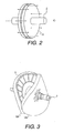
- Figure 2 is perspective view of a rotor of the axial gap type motor/generator illustrated in Figure 1 .
- the center plane of the cross section of the axial gap type motor/generator includes a center rotational axis O.
- the motor/generator basically has a rotor 1, a rotor shaft 2, a motor case 5 and a stator 6.
- the rotor 1 includes a pair of circular disk-shaped rotor parts 1A.
- the rotor parts 1A are fixedly connected to a rotor shaft 2 such that the rotor parts 1A cannot rotate relative to the rotor shaft 2.
- the rotor shaft 2 is arranged to extend along the center rotational axis O, which is indicated with a single-dot chain line.
- the shaft 2 is rotatably supported to the motor case 5.
- the rotor parts 1A have inner surfaces that face toward the stator 6 across air (axial) gaps 4 that exist axially between the rotor parts 1A and the stator 6.
- the stator 6 is fixed to the motor case 5.
- the stator 6 has an annular shape with a hole 7 in a middle portion thereof.
- the rotor shaft 2 passes through the hole 7 such that the rotor parts 1A are arranged on both sides of the stator 6 along the direction of the center rotational axis O.
- the stator 6 is provided with a plurality of stator iron cores 8 that are arranged along a circumferential direction such that each of the stator iron cores 8 extends in a direction parallel to the center rotational axis O.
- a coil 9 is wound onto each of the stator iron cores 8.
- Permanent magnets 3 are arranged circumferentially in the inner surfaces of the rotor parts 1A in such positions that they face across from the ends of the iron cores 8 of the stator 6.
- stator iron cores 8 are arranged circumferential on the stator and the teeth can be configured to serve as stator iron cores.
- stator iron cores 8 are thought of as comprising portions lying between slots or as comprising teeth depending on the type and shape of the stator 6, the number of stator iron cores 8 will be equal to the number of slots, which expresses the specification of the stator of the motor/generator.
- An alternating current control device 10 is operatively connected to the coils 9 for controlling the alternating current flowing in the coils 9.
- the alternating current control device 10 is configured to execute alternating current control of a single phase or multiple phase alternating current flowing in the coils 9.
- the alternating current control device 10 includes a superpositioning control section and a frequency component control section that cooperate to control the alternating current flowing in the coils 9.
- the alternating current control device 10 includes a microcomputer with an alternating current control program (the superpositioning control section and the frequency component control section) that controls the current flowing in the coils 9.
- the superpositioning control section is configured to produce the alternating current by superpositioning a plurality of frequency components including a first order fundamental wave component and a plurality of higher harmonic wave components that have frequencies equal to integer multiples of a frequency of the fundamental wave components and are of orders that are equal to values of the integer multiples.
- the frequency component control section is configured to control a relationship among the frequency components such that two pairs of the frequency components whose orders differ by two are aligned with respect to each other.
- the planar mode of vibration described above can be reduced to an appropriate degree by stipulating a relationship among the superpositioned frequency components of current flowing in the stator coils 9 such that two pairs of frequency components whose orders differ by 2 are aligned with each other. Also the alternating current control device 10, even if there are high orders of planar order vibration, the orders of the higher harmonic wave components can be reduced, making it easier to control the higher harmonic wave components. As a result, planar mode vibrations can be eliminated or effectively reduced even in axial gap type motor generators having larger numbers of poles.
- the axial gap type motor/generator shown in Figure 1 can be either a single phase motor/generator or a multiple phase motor/generator having three or more phases.
- a magnetic flux is generated that passes through the stator iron cores 8 and the magnetic flux passes across the axial gaps 4 to form a magnetic circuit with the permanent magnets 3 of the rotor parts 1A arranged on both sides of the stator 6.
- the rotor parts 1A are rotated by controlling the frequency components of the alternating current flowing in the coils 9 (or the alternating voltage).
- the current in the coils 9 comprises a plurality of superpositioned frequency components.
- the frequency components include a fundament component of the sine wave and higher harmonic wave components.
- a planar mode of vibration occurs in which the rotor parts 1A deform along the direction of the center rotational axis O. At certain rotational speeds of the rotor parts 1A, this planar mode of vibration becomes prominent and a planar mode of resonance occurs.
- the axial gap motor/generator is an 18-slot, 20-pole type having 18 stator iron cores 8 and 20 permanent magnets 3 arranged circumferentially, then the order number of the planar mode of vibration will be two (second order), which is equal to the difference between the number of slots and the number of permanent magnets 3.
- the second order planar mode of vibration is shown in Figure 3 .
- the resonance will be the
- the rotational speed (e.g., revolutions per minute) at which the rotor parts 1A resonate varies depending on the size and dimensions of the axial gap motor/generator.
- Figure 4 shows an example of a plot of the amplitude (equal to deformation amount of the rotor 1) of the planar mode of vibration versus the rotational speed (rpm) for a motor/generator according to this embodiment.
- the deformation amount of the rotor 1 exceeds an allowable deformation limit amount of deformation (indicated with a thin-line) by 100 times at a rotor rotational speed of 5600 rpm.
- an alternating current control is executed which is configured to produce an alternating current in the coils 9 that includes a plurality of superpositioned frequency components that include a first order fundamental wave component and a plurality of higher harmonic wave components that have frequencies equal to integer multiples of the frequency of the fundamental wave component and are of orders that are equal to the values of the integer multiples.
- the alternating current control is further configured to control a relationship among the frequency components such that two pairs of frequency components whose orders differ by 2 are aligned with each other.
- the alternating current control just described is executed when the rotational speed is in the vicinity of 5600 rpm, which is where the planar mode resonance occurs. More specifically, as shown in Figure 4 , the alternating current control is executed when the rotational speed is in a region ranging from approximately 3900 rpm to 7000 rpm, in which region the deformation amount, i.e., the amplitude of the planar mode resonance, exceeds the allowable deformation limit amount.
- the alternating current control produces a multiple-phase alternating current I(t) in the coils 9 by superpositioning a sinusoidal fundamental wave component, a third order higher harmonic wave (frequency) component having a frequency three times larger than the frequency of the fundamental wave component, and a fifth order higher harmonic wave (frequency) component having a frequency five times larger than the frequency of the fundamental wave component.
- Each of these components is an nth order higher harmonic wave (frequency) component having a frequency equal to n times the frequency of the fundamental wave component (where n is an integer).
- I t A ⁇ 1 ⁇ sin ( ⁇ t + ⁇ ⁇ 1 ) + A ⁇ 3 ⁇ sin ( 3 ⁇ ⁇ t + ⁇ ⁇ 3 ) + A ⁇ 5 ⁇ sin 5 ⁇ ⁇ t + ⁇ ⁇ 5
- t time
- ⁇ angular velocity
- A1 is a coefficient determining the amplitude of the fundamental wave component
- B1 is a coefficient determining the phase of the fundamental wave component
- A3 is coefficient determining the amplitude of the third order higher harmonic wave component
- B3 is a coefficient determining the phase the third order higher harmonic wave component
- A5 is coefficient determining the amplitude of the fifth order higher harmonic wave component
- B5 is a coefficient determining the phase the fifth order higher harmonic wave component.
- the multiple-phase alternating current I(t) fed to the coils 9 is produced by superpositioning the first order fundament wave component, the third order higher harmonic wave component, and the fifth order higher harmonic wave component, and a relationship among the first, third, and fifth order frequency components is controlled such that that a pair of frequency components comprising the first order frequency component and the third order frequency component (whose orders differ by 2) and a pair of frequency components comprising the third order frequency component and the fifth order frequency component (whose orders differ by 2) are aligned with each other.
- a low order planar vibrational resonance can be eliminated or reduced because the current is controlled such that two pairs of frequency components whose orders differ by 2 are aligned with each other.
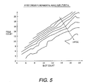
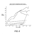
- Figures 5 to 10 are maps used for determining the values of the coefficients in the case of an axial gap type motor/generator having a number of slots (slot count) S (also equal to the number of stator iron cores 8) and a number of poles (pole count) P.
- slot count S (also equal to the number of stator iron cores 8)
- pole count pole count
- the number of slots is indicted on a horizontal axis and the number of poles is indicated on a vertical axis.
- the slot count is equal to the number of stator iron cores 8 shown in Figure 1 .
- the alternating current control device 10 executes the alternating current control to regulate the alternating current flowing in the coils 9 control by referring to the maps shown in Figures 5 to 10 to determine values of the coefficients A1, ⁇ 1, A3, ⁇ 3, A5 and ⁇ 5, respectively, that will achieve an effect of reducing the planar mode of vibration to at least a prescribed degree. These maps are obtained by experimentation or computer simulation. When the coefficients A1, ⁇ 1, A3, ⁇ 3, A5 and ⁇ 5 have been determined, an effect of reducing the deformation caused by (i.e., reducing the amplitude of) the planar mode vibration to at least a prescribed degree (e.g., by a factor of 100) is obtained. When a size/dimension of the axial gap type motor/generator is changed, it is necessary to prepare these maps again by experimentation or computer simulation.
- Figure 11 illustrates the effect of reducing the deformation resulting from planar mode vibration (i.e., reducing the amplitude) that is obtained with an axial gap type motor/generator in accordance with the first example.
- the horizontal axis indicates the rotational speed of the rotor parts 1A and the vertical axis indicates the deformation amount (amplitude).
- deformations amounts (amplitudes) that result when the alternating current is produced with only the first order fundamental component are indicated with solid black dots.
- deformations amounts (amplitudes) that result when the alternating current is produced with the first order fundamental component, the third order higher harmonic wave component, and the fifth order higher harmonic wave component are indicated with white dots.
- Figure 11 shows a large number of experimental data, each comprising a pair of dots (one black, one white) corresponding to the same rotational speed.
- the results for the rotor rotational speed 6600 rpm are enclosed in a broken-line circle in Figure 11 and illustrate where the first example reduces the planar mode vibration in the most effective manner.
- the deformation amount (amplitude) can be reduced in an effective manner in the vicinity of the rotor rotational speed (5900 rpm) at which planar mode resonance occurs.
- the radius and axial thickness of the rotor parts 1A is selected appropriately and the size and dimensions of the axial gap type motor generator are designed such that the rotor rotational speed at which planar mode resonance occurs is in a lower rotational speed region that lies on a low side of a rotational speed region in which the motor/generator is normally used. In this way, the higher harmonic frequencies can be lowered and controlled more easily.
- Figure 12 shows a waveform of an alternating current produced with an alternating current control based on the equation (1).
- the electrical angle is indicated on the horizontal axis and the current is indicated on the vertical axis.
- the thin-line indicates the first order fundamental wave component and the bold-line indicates a multiple-phase alternating current of the coils 9 obtained by superpositioning the first order fundamental component, the third order higher harmonic wave component, and the fifth order higher harmonic wave component.
- the alternating current control produces a multiple-phase alternating current to be fed to the coils 9 by superpositioning a sinusoidal fundamental wave (frequency) component, a fifth order higher harmonic wave (frequency) component having a frequency five times larger than the frequency of the fundamental wave component, a seventh order higher harmonic wave (frequency )component having a frequency five times larger than the frequency of the fundamental wave component, an eleventh order higher harmonic wave (frequency) component having a frequency eleven times larger than the frequency of the fundamental wave component, and a thirteenth order higher harmonic wave component having a frequency thirteen times larger than the frequency of the fundamental wave component.
- the multiple-phase alternating current I(t) fed to the coils 9 is produced by superpositioning the first order fundament wave component, the fifth order higher harmonic wave component, the seventh order higher harmonic wave component, the eleventh order higher harmonic wave component, and the thirteenth order higher harmonic wave component and a relationship among the first, fifth, seventh, eleventh, and thirteenth order frequency components is controlled such that that a pair of frequency components comprising the fifth order frequency component and the seventh order frequency component (whose orders differ by 2) and a pair of frequency components comprising the eleventh order frequency component and the thirteenth order frequency component (whose orders differ by 2) are aligned with each other.
- a low order planar vibrational resonance can be eliminated or reduced because the current is controlled such that two pairs of frequency components whose orders differ by 2 are aligned with each other.
- the coefficients for the different frequency components should be set such that the deformation resulting from the planar mode vibration (i.e., the amplitude of the planar mode vibration) is reduced to at least a prescribed degree (e.g., by a factor of 100).
- the alternating current control of the second example can also be applied to an axial gap type motor/generator uses a single-phase alternating current or a multiple-phase current having frequency components other than frequencies equal to 5, 7, 11, and 13 times the fundamental frequency.
- the alternating current controls presented in the first and second examples disclose the results of research conducted to discover combinations of higher harmonic wave components that reduce planar mode vibration in an effective manner. More specifically, it was discovered that a unique effect of eliminating or appropriately reducing the planar modes of vibration described above can be obtained by sending alternating current to the coil of a synchronous motor/generator where the alternating current has two superpositioned pairs of frequency components whose orders differ by 2 (i.e., the orders of the frequency components of each pair differ by 2).
- Both the first and second examples relate to an alternating current control apparatus for an axial gap type motor/generator ( Figures 1 to 3 ) comprising a comprising a stator 6 having a plurality of circumferentially arranged stator iron cores 8 onto which a coil 9 is wound and a rotor 1 that has a plurality of magnetic poles and is arranged facing the stator 6 along the direction of a center rotational axis O.
- the alternating current control apparatus controls a single phase or a multiple phase alternating current flowing in the coil 9 of the axial gap type motor/generator.
- the alternating current control apparatus produces the single phase or multiple phase alternating current by superpositioning a plurality of frequency components, the plurality of frequency components comprising a first order fundamental wave and a plurality of higher harmonic wave components that have frequencies equal to integer multiples of the frequency of the fundamental wave component and are of orders that are equal to the values of the integer multiples.
- planar mode of vibration can be eliminated or reduced in an effective manner even if the axial gap type motor/generator has a large number of poles and the difference between the number of slots and the number of poles is small.
- fourth and higher orders of planar mode vibration can also be eliminated.
- the higher harmonic wave components are the third order and fifth order components.
- the alternating current control can be accomplished easily because the higher harmonic wave components used are lower order harmonics.
- the alternating current control can also be accomplished more easily because there are only two higher harmonic wave components.
- the alternating current control can also be applied to an axial gap type motor/generator configured to use a single-phase alternating current or a multiple-phase current having frequency components other than frequencies equal to 3 and 5 times the fundamental frequency.
- the alternating current control is not limited to eliminating second order planar mode vibration (see Figure 3 ) when the difference between the number of slots (e.g., 18) and the number of poles (e.g., 20) is 2. Instead, the alternating current control can eliminate fourth order or higher order planar deformation when the difference between the number of slots and the number of poles is 4 or higher.
- the alternating current I(t) fed to the coils 9 is controlled by the equation (1).
- the coefficients A1 and ⁇ 1, the coefficients A3 and ⁇ 3, and the coefficients A5 and ⁇ 5 are set such that an effect of reducing an order of a planar mode vibration of the rotor 1 is achieved to a prescribed degree, the planar vibration being a vibration involving deformation of the rotor 1 oriented along the direction of the center rotational axis O and the order of the planar vibration being equal to a difference between the number of stator iron cores 8 (slot count) and the number of magnetic poles of the rotor 1.
- a current control in accordance with this embodiment can be applied to axial gap type motor/generators having a variety of slot counts and pole counts.
- the higher harmonic wave components are the fifth, seventh, eleventh, and thirteenth order components.
- planar mode vibrations can be eliminated or reduced in a three-phase motor/generator by using lower-order higher harmonic wave components.
- the alternating current control is not limited to eliminating second order planar mode vibration (see Figure 3 ) when the difference between the number of slots (e.g., 18) and the number of poles (e.g., 20) is 2. Instead, the alternating current control can eliminate fourth order or higher order planar deformation when the difference between the number of slots and the number of poles is 4 or higher.
- alternating current control it is beneficial for the alternating current control according to the first and second examples to be executed when the rotational speed of the rotor 1 is in the vicinity of a rotational speed, among rotational speeds at which the rotor 1 resonates, at which the rotor 1 undergoes a planar resonance in which the rotor 1 deforms in a rotor axial direction.
- planar mode vibration can be eliminated or reduced as appropriate in accordance with the operating state of the axial gap type motor/generator.
- the radius and the thickness along the direction of the center rotational axis O of the rotor 1 should be selected and the size/dimensions of the axial gap type motor/generator should be designed such that the rotor rotational speed at which the rotor undergoes a planar mode of resonance is in a low rotational speed region that lies on a low side of a prescribed operating rotational speed region in which the axial gap type motor/generator is normally used. In this way, the occurrence of planar mode vibration can be suppressed.
- the term “comprising” and its derivatives, as used herein, are intended to be open ended terms that specify the presence of the stated features, elements, components, groups, integers, and/or steps, but do not exclude the presence of other unstated features, elements, components, groups, integers and/or steps.
- the foregoing also applies to words having similar meanings such as the terms, “including”, “having” and their derivatives.
- the terms “part,” “section,” “portion,” “member” or “element” when used in the singular can have the dual meaning of a single part or a plurality of parts.
- the terms of degree such as “substantially”, “about” and “approximately” as used herein mean a reasonable amount of deviation of the modified term such that the end result is not significantly changed.
Landscapes
- Engineering & Computer Science (AREA)
- Power Engineering (AREA)
- Control Of Ac Motors In General (AREA)
- Permanent Magnet Type Synchronous Machine (AREA)
Abstract
Description
- The present invention generally relates to an axial gap type motor/generator and particularly, but not exclusively, to controlling an axial gap type motor/generator having a stator and a rotor arranged to face across from each other along an axial direction so as to prevent or reduce a planar mode of vibration of the rotor in which the rotor deforms in an axial direction. Aspects of the invention relate to an apparatus, to a motor/generator, to a method and to a vehicle.
- The alternating current (AC) motor/generators used as power sources in electric automobiles, hybrid automobiles and fuel cell automobiles are designed for large outputs. The magnetic noise emitted from this kind of large output AC motor/generator can be a problem. Since the rotational speeds at which such an AC motor/generator is used range widely from a low rotational speed region to a high rotational speed region, rotor vibration occurring when the rotor of the AC motor/generator rotates can also be a problem. There are known technologies for alleviating these problems. One example of such a technology is disclosed in Japanese Laid-Open Patent Publication No.
2005-304237 - The technology disclosed in Japanese Laid-Open Patent Publication No.
2005-304237 2005-304237 2005-304237 - In recent years, in order to obtain a motor with a higher torque, research has been conducted to increase the number of poles in an axial gap type motor generator having a rotor and a stator that are arranged to face each other along an axial direction. More specifically, in such an axial motor/generator, a rotor has a small dimension along the direction of the center axis thereof and a large dimension in a radial direction. A large number of permanent magnets are arranged along a circumferential direction of the rotor such that the rotor has a large number of poles.
- Another arrangement is a two-rotor, one-stator motor/generator in which two circular disk-shaped rotor parts are mounted on a common shaft with a stator arranged between the two rotor parts. In such an axial gap motor/generator, vibrations can cause a problem in a planar mode of vibration in which the rotor parts undergoes deformation along the axial directions. The rotor parts are deformed due to a low-order planar mode of deformation. As the order of the planar vibration becomes higher, the number of bent locations becomes larger. More specifically, the first to fourth orders of planar mode vibration are typically a problem.
- If the technology disclosed in Japanese Laid-Open Patent Publication No.
2005-304237 2005-304237 - The only order of planar mode vibration against which the technology of disclosed in Japanese Laid-Open Patent Publication No.
2005-304237 2005-304237 - The present invention aims to solve one or more of the above mentioned problems and to improve upon such known technology. Embodiments of the invention may therefore provide a technology that can effectively prevent planar mode vibration in an axial gap type motor/generator. In particular, the present applicants have discovered that an effect of eliminating or appropriately reducing the planar modes of vibration described above can be obtained by sending to the coil of a synchronous motor/generator an alternating current that has two superpositioned pairs of frequency components whose orders differ by 2 (i.e., the orders of the frequency components of each pair differ by 2). Other aims and advantages of the invention will become apparent from the following description, claims and drawings.
- Aspects of the invention therefore provide an apparatus, a motor/generator, a method and a vehicle as claimed in the appended claims.
- According to another aspect of the invention for which protection is sought there is provided an axial gap type motor/generator comprising a stator including a plurality of stator iron cores with a coil disposed on each of the stator iron cores, a rotor facing the stator, with the rotor including a plurality of magnetic poles and an alternating current control device configured to execute alternating current control of a single phase or multiple phase alternating current flowing in the coils, the alternating current control device including a superpositioning control section configured to produce the alternating current by superpositioning a plurality of frequency components including a first order fundamental wave component and a plurality of higher harmonic wave components that have frequencies equal to integer multiples of a frequency of the fundamental wave components and are of orders that are equal to values of the integer multiples and a frequency component control section configured to control a relationship among the frequency components such that two pairs of the frequency components whose orders differ by two are aligned with respect to each other.
- In an embodiment, the frequency component control section is further configured to control a third order frequency component and a fifth order frequency component as the higher harmonic wave components.
- In an embodiment, the superpositioning control section produces the alternating current as follows:

where t is time, ω is angular velocity, A1 and B1 are coefficients for the fundamental wave component, A3 and B3 are coefficients for the third order frequency component and A5 and B5 are coefficients for the fifth order frequency component. - In an embodiment, the frequency component control section is configured to set the coefficients to values that reduce an order of a planar mode of vibration of the rotor to approach a prescribed degree, in which the order is equal to a difference between a number of the stator iron cores and a number of the magnetic poles of the rotor, and the planar mode of vibration being a vibration involving deformation of the rotor in an axial direction.
- In an embodiment, the frequency component control section is configured to control a fifth order frequency component, a seventh order frequency component, an eleventh order frequency component, and a thirteenth order frequency component as the higher harmonic wave components.
- In an embodiment, the alternating current control device is configured to execute the alternating current control when a rotational speed of the rotor is in a vicinity of a rotational speed at which the rotor undergoes a planar mode of resonance resulting in the rotor deforming in a rotor axial direction.
- In an embodiment, the rotor and the stator are dimensioned such that the rotor rotational speed at which the rotor undergoes the planar mode of resonance is in a low rotational speed region that lies on a low rotational speed side of a prescribed operating rotational speed region in which the axial gap type motor/generator is normally used.
- According to a further aspect of the invention for which protection is sought there is provided an axial gap type motor/generator comprising stator means for receiving alternating current, magnetic rotor means for rotating relative to the stator means and alternating current control means for executing alternating current control of the alternating current flowing in the stator means to produce the alternating current by superpositioning a plurality of frequency components including a first order fundamental wave component and a plurality of higher harmonic wave components that have frequencies equal to integer multiples of a frequency of the fundamental wave components and are of orders that are equal to values of the integer multiples, and to control a relationship among the frequency components such that two pairs of the frequency components whose orders differ by two are aligned with respect to each other.
- According to a still further aspect of the invention for which protection is sought there is provided a method of controlling an axial gap type motor/generator having a stator including a plurality of stator iron cores with a coil disposed on each of the stator iron cores and a rotor facing the stator, with the rotor including a plurality of magnetic poles, the method comprising producing alternating current in coils of the stator by superpositioning a plurality of frequency components including a first order fundamental wave component and a plurality of higher harmonic wave components that have frequencies equal to integer multiples of a frequency of the fundamental wave components and are of orders that are equal to values of the integer multiples and control a relationship among the frequency components such that two pairs of the frequency components whose orders differ by two are aligned with respect to each other.
- For example, an axial gap type motor/generator may comprise a stator, a rotor and an alternating current control device. The stator may include a plurality of stator iron cores with a coil disposed on each of the stator iron cores. The rotor faces the stator, with the rotor includes a plurality of magnetic poles. The alternating current control device is configured to execute alternating current control of a single phase or multiple phase alternating current flowing in the coils. The alternating current control device may include a superpositioning control section and a frequency component control section. The superpositioning control section is configured to produce the alternating current by superpositioning a plurality of frequency components including a first order fundamental wave component and a plurality of higher harmonic wave components that have frequencies equal to integer multiples of a frequency of the fundamental wave components and are of orders that are equal to values of the integer multiples. The frequency component control section is configured to control a relationship among the frequency components such that two pairs of the frequency components whose orders differ by two are aligned with respect to each other.
- Within the scope of this application it is envisaged that the various aspects, embodiments, examples, features and alternatives set out in the preceding paragraphs, in the claims and/or in the following description and drawings, may be taken individually or in any combination thereof.
- The present invention will now be described, by way of example only, with reference to the accompanying drawings in which:
-
Figure 1 is a simplified vertical cross sectional view of an axial gap type motor/generator equipped with an alternating current control device in accordance with one embodiment; -
Figure 2 is a perspective view of the rotor of the axial gap type motor/generator illustrated inFigure 1 ; -
Figure 3 is a simplified perspective view illustrating a planar mode of vibration in the axial gap type motor/generator illustrated inFigure 1 ; -
Figure 4 is a graph plotting the deformation amount resulting from (amplitude of) planar mode vibration versus the rotor rotational speed; -
Figure 5 is a map for determining a coefficient of a first order frequency component used in an alternating current control; -
Figure 6 is a map for determining a coefficient of a first order frequency component used in an alternating current control; -
Figure 7 is a map for determining a coefficient of a third order frequency component used in an alternating current control; -
Figure 8 is a map for determining a coefficient of a third order frequency component used in an alternating current control; -
Figure 9 is a map for determining a coefficient of a fifth order frequency component used in an alternating current control; -
Figure 10 is a map for determining a coefficient of a fifth order frequency component used in an alternating current control; -
Figure 11 illustrates the effect of reducing the deformation resulting from (i.e. the amplitude of) the planar mode vibration achieved with the same alternating current control; and -
Figure 12 illustrates a waveform of an alternating current produced with the same alternating current control. - Selected embodiments of the present invention will now be explained with reference to the drawings. It will be apparent to those skilled in the art from this disclosure that the following descriptions of the embodiments of the present invention are provided for illustration only and not for the purpose of limiting the invention as defined by the appended claims and their equivalents.
- Referring initially to
Figure 1 , a simplified vertical cross sectional view of a two-rotor one-stator axial gap type motor/generator is illustrated that is equipped with an alternating current control apparatus in accordance with one illustrated embodiment.Figure 2 is perspective view of a rotor of the axial gap type motor/generator illustrated inFigure 1 . The center plane of the cross section of the axial gap type motor/generator includes a center rotational axis O. The motor/generator basically has arotor 1, arotor shaft 2, amotor case 5 and astator 6. Therotor 1 includes a pair of circular disk-shapedrotor parts 1A. Therotor parts 1A are fixedly connected to arotor shaft 2 such that therotor parts 1A cannot rotate relative to therotor shaft 2. Therotor shaft 2 is arranged to extend along the center rotational axis O, which is indicated with a single-dot chain line. Theshaft 2 is rotatably supported to themotor case 5. Therotor parts 1A have inner surfaces that face toward thestator 6 across air (axial)gaps 4 that exist axially between therotor parts 1A and thestator 6. Thestator 6 is fixed to themotor case 5. Thestator 6 has an annular shape with ahole 7 in a middle portion thereof. Therotor shaft 2 passes through thehole 7 such that therotor parts 1A are arranged on both sides of thestator 6 along the direction of the center rotational axis O. - The
stator 6 is provided with a plurality ofstator iron cores 8 that are arranged along a circumferential direction such that each of thestator iron cores 8 extends in a direction parallel to the center rotational axis O. Acoil 9 is wound onto each of thestator iron cores 8.Permanent magnets 3 are arranged circumferentially in the inner surfaces of therotor parts 1A in such positions that they face across from the ends of theiron cores 8 of thestator 6. - Although not shown in the figures, it is possible to provide a plurality of slots arranged along a circumferential direction in the
stator 6 with thestator iron cores 8 arranged between adjacent slots. Alternately, if the axial gap motor/generator is of the one-rotor one-stator type, then teeth can be arranged circumferential on the stator and the teeth can be configured to serve as stator iron cores. Thus, regardless of whether thestator iron cores 8 are thought of as comprising portions lying between slots or as comprising teeth depending on the type and shape of thestator 6, the number ofstator iron cores 8 will be equal to the number of slots, which expresses the specification of the stator of the motor/generator. - An alternating
current control device 10 is operatively connected to thecoils 9 for controlling the alternating current flowing in thecoils 9. In particular, as discussed below in more detail, the alternatingcurrent control device 10 is configured to execute alternating current control of a single phase or multiple phase alternating current flowing in thecoils 9. The alternatingcurrent control device 10 includes a superpositioning control section and a frequency component control section that cooperate to control the alternating current flowing in thecoils 9. The alternatingcurrent control device 10 includes a microcomputer with an alternating current control program (the superpositioning control section and the frequency component control section) that controls the current flowing in thecoils 9. Basically, the superpositioning control section is configured to produce the alternating current by superpositioning a plurality of frequency components including a first order fundamental wave component and a plurality of higher harmonic wave components that have frequencies equal to integer multiples of a frequency of the fundamental wave components and are of orders that are equal to values of the integer multiples. The frequency component control section is configured to control a relationship among the frequency components such that two pairs of the frequency components whose orders differ by two are aligned with respect to each other. - With the alternating
current control device 10, the planar mode of vibration described above can be reduced to an appropriate degree by stipulating a relationship among the superpositioned frequency components of current flowing in the stator coils 9 such that two pairs of frequency components whose orders differ by 2 are aligned with each other. Also the alternatingcurrent control device 10, even if there are high orders of planar order vibration, the orders of the higher harmonic wave components can be reduced, making it easier to control the higher harmonic wave components. As a result, planar mode vibrations can be eliminated or effectively reduced even in axial gap type motor generators having larger numbers of poles. - The axial gap type motor/generator shown in
Figure 1 can be either a single phase motor/generator or a multiple phase motor/generator having three or more phases. When current flows through thecoils 9, a magnetic flux is generated that passes through thestator iron cores 8 and the magnetic flux passes across theaxial gaps 4 to form a magnetic circuit with thepermanent magnets 3 of therotor parts 1A arranged on both sides of thestator 6. Therotor parts 1A are rotated by controlling the frequency components of the alternating current flowing in the coils 9 (or the alternating voltage). The current in thecoils 9 comprises a plurality of superpositioned frequency components. The frequency components include a fundament component of the sine wave and higher harmonic wave components. - With the axial gap type motor/generator, a planar mode of vibration occurs in which the
rotor parts 1A deform along the direction of the center rotational axis O. At certain rotational speeds of therotor parts 1A, this planar mode of vibration becomes prominent and a planar mode of resonance occurs. If, for example, the axial gap motor/generator is an 18-slot, 20-pole type having 18stator iron cores permanent magnets 3 arranged circumferentially, then the order number of the planar mode of vibration will be two (second order), which is equal to the difference between the number of slots and the number ofpermanent magnets 3. The second order planar mode of vibration is shown inFigure 3 . As shown inFigure 3 , is therotor parts 1A are deformed into a saddle-like shape. As the torque of the motor/generator becomes higher, the greater the deformation of therotor parts 1A becomes due to the low-order planar mode of vibration. - If the axial gap motor/generator has S slots and P poles, then the resonance will be the |P - S| order of the planar mode vibration. The rotational speed (e.g., revolutions per minute) at which the
rotor parts 1A resonate varies depending on the size and dimensions of the axial gap motor/generator. - It is advantageous for the number of slots S and the number of poles P to be close to each other in order to improve the torque density of the motor and to improve the motor efficiency. However, when the difference |P - S| is small, a low order planar mode resonance like that shown in
Figure 3 becomes a problem because asufficient air gap 4 cannot be secured if the deformation resulting from the planar mode resonance is large. -
Figure 4 shows an example of a plot of the amplitude (equal to deformation amount of the rotor 1) of the planar mode of vibration versus the rotational speed (rpm) for a motor/generator according to this embodiment. As indicated with the bold-line curve, the deformation amount of therotor 1 exceeds an allowable deformation limit amount of deformation (indicated with a thin-line) by 100 times at a rotor rotational speed of 5600 rpm. - In order to keep the deformation amount of the
rotor 1, i.e., the amplitude of the planar mode resonance, from exceeding the allowable deformation limit amount, an alternating current control is executed which is configured to produce an alternating current in thecoils 9 that includes a plurality of superpositioned frequency components that include a first order fundamental wave component and a plurality of higher harmonic wave components that have frequencies equal to integer multiples of the frequency of the fundamental wave component and are of orders that are equal to the values of the integer multiples. The alternating current control is further configured to control a relationship among the frequency components such that two pairs of frequency components whose orders differ by 2 are aligned with each other. - In this embodiment, the alternating current control just described is executed when the rotational speed is in the vicinity of 5600 rpm, which is where the planar mode resonance occurs. More specifically, as shown in
Figure 4 , the alternating current control is executed when the rotational speed is in a region ranging from approximately 3900 rpm to 7000 rpm, in which region the deformation amount, i.e., the amplitude of the planar mode resonance, exceeds the allowable deformation limit amount. - A first example in which an alternating current control will now be explained in which the axial gap type motor generator is configured basically as shown in
Figure 1 as a seven-phase motor/generator having 18 slots and 20 poles. - In the first example, the alternating current control produces a multiple-phase alternating current I(t) in the
coils 9 by superpositioning a sinusoidal fundamental wave component, a third order higher harmonic wave (frequency) component having a frequency three times larger than the frequency of the fundamental wave component, and a fifth order higher harmonic wave (frequency) component having a frequency five times larger than the frequency of the fundamental wave component. Each of these components is an nth order higher harmonic wave (frequency) component having a frequency equal to n times the frequency of the fundamental wave component (where n is an integer). When expressed as an equation, the current is as follows.
- In the equation, t is time, ω is angular velocity, A1 is a coefficient determining the amplitude of the fundamental wave component, B1 is a coefficient determining the phase of the fundamental wave component, A3 is coefficient determining the amplitude of the third order higher harmonic wave component, B3 is a coefficient determining the phase the third order higher harmonic wave component, A5 is coefficient determining the amplitude of the fifth order higher harmonic wave component, and B5 is a coefficient determining the phase the fifth order higher harmonic wave component.
- In the first example, the multiple-phase alternating current I(t) fed to the
coils 9 is produced by superpositioning the first order fundament wave component, the third order higher harmonic wave component, and the fifth order higher harmonic wave component, and a relationship among the first, third, and fifth order frequency components is controlled such that that a pair of frequency components comprising the first order frequency component and the third order frequency component (whose orders differ by 2) and a pair of frequency components comprising the third order frequency component and the fifth order frequency component (whose orders differ by 2) are aligned with each other. - Thus, with the first example, a low order planar vibrational resonance can be eliminated or reduced because the current is controlled such that two pairs of frequency components whose orders differ by 2 are aligned with each other.
- The coefficients A1, β1, A3, β3, A5, and β5 will now be explained.
Figures 5 to 10 are maps used for determining the values of the coefficients in the case of an axial gap type motor/generator having a number of slots (slot count) S (also equal to the number of stator iron cores 8) and a number of poles (pole count) P. In each of the maps, the number of slots is indicted on a horizontal axis and the number of poles is indicated on a vertical axis. The slot count is equal to the number ofstator iron cores 8 shown inFigure 1 . - The alternating
current control device 10 executes the alternating current control to regulate the alternating current flowing in thecoils 9 control by referring to the maps shown inFigures 5 to 10 to determine values of the coefficients A1, β1, A3, β3, A5 and β5, respectively, that will achieve an effect of reducing the planar mode of vibration to at least a prescribed degree. These maps are obtained by experimentation or computer simulation. When the coefficients A1, β1, A3, β3, A5 and β5 have been determined, an effect of reducing the deformation caused by (i.e., reducing the amplitude of) the planar mode vibration to at least a prescribed degree (e.g., by a factor of 100) is obtained. When a size/dimension of the axial gap type motor/generator is changed, it is necessary to prepare these maps again by experimentation or computer simulation. -
Figure 11 illustrates the effect of reducing the deformation resulting from planar mode vibration (i.e., reducing the amplitude) that is obtained with an axial gap type motor/generator in accordance with the first example. The horizontal axis indicates the rotational speed of therotor parts 1A and the vertical axis indicates the deformation amount (amplitude). InFigure 11 , deformations amounts (amplitudes) that result when the alternating current is produced with only the first order fundamental component are indicated with solid black dots. Conversely, deformations amounts (amplitudes) that result when the alternating current is produced with the first order fundamental component, the third order higher harmonic wave component, and the fifth order higher harmonic wave component are indicated with white dots.Figure 11 shows a large number of experimental data, each comprising a pair of dots (one black, one white) corresponding to the same rotational speed. The results for the rotor rotational speed 6600 rpm are enclosed in a broken-line circle inFigure 11 and illustrate where the first example reduces the planar mode vibration in the most effective manner. - With the alternating current control of the first example, the deformation amount (amplitude) can be reduced in an effective manner in the vicinity of the rotor rotational speed (5900 rpm) at which planar mode resonance occurs.
- The radius and axial thickness of the
rotor parts 1A is selected appropriately and the size and dimensions of the axial gap type motor generator are designed such that the rotor rotational speed at which planar mode resonance occurs is in a lower rotational speed region that lies on a low side of a rotational speed region in which the motor/generator is normally used. In this way, the higher harmonic frequencies can be lowered and controlled more easily. -
Figure 12 shows a waveform of an alternating current produced with an alternating current control based on the equation (1). InFigure 12 , the electrical angle is indicated on the horizontal axis and the current is indicated on the vertical axis. InFigure 12 , the thin-line indicates the first order fundamental wave component and the bold-line indicates a multiple-phase alternating current of thecoils 9 obtained by superpositioning the first order fundamental component, the third order higher harmonic wave component, and the fifth order higher harmonic wave component. - A second example in which an alternating current control will now be explained in which the axial gap type motor generator is configured basically as shown in
Figure 1 as a three-phase motor/generator having 18 slots and 20 poles. - In the second example, the alternating current control produces a multiple-phase alternating current to be fed to the
coils 9 by superpositioning a sinusoidal fundamental wave (frequency) component, a fifth order higher harmonic wave (frequency) component having a frequency five times larger than the frequency of the fundamental wave component, a seventh order higher harmonic wave (frequency )component having a frequency five times larger than the frequency of the fundamental wave component, an eleventh order higher harmonic wave (frequency) component having a frequency eleven times larger than the frequency of the fundamental wave component, and a thirteenth order higher harmonic wave component having a frequency thirteen times larger than the frequency of the fundamental wave component. - In the second example, the multiple-phase alternating current I(t) fed to the
coils 9 is produced by superpositioning the first order fundament wave component, the fifth order higher harmonic wave component, the seventh order higher harmonic wave component, the eleventh order higher harmonic wave component, and the thirteenth order higher harmonic wave component and a relationship among the first, fifth, seventh, eleventh, and thirteenth order frequency components is controlled such that that a pair of frequency components comprising the fifth order frequency component and the seventh order frequency component (whose orders differ by 2) and a pair of frequency components comprising the eleventh order frequency component and the thirteenth order frequency component (whose orders differ by 2) are aligned with each other. - Thus, with the second example, a low order planar vibrational resonance can be eliminated or reduced because the current is controlled such that two pairs of frequency components whose orders differ by 2 are aligned with each other.
- The coefficients for the different frequency components should be set such that the deformation resulting from the planar mode vibration (i.e., the amplitude of the planar mode vibration) is reduced to at least a prescribed degree (e.g., by a factor of 100).
- In addition to a three-phase AC motor/generator having 18 slots and 20 poles, the alternating current control of the second example can also be applied to an axial gap type motor/generator uses a single-phase alternating current or a multiple-phase current having frequency components other than frequencies equal to 5, 7, 11, and 13 times the fundamental frequency.
- The alternating current controls presented in the first and second examples disclose the results of research conducted to discover combinations of higher harmonic wave components that reduce planar mode vibration in an effective manner. More specifically, it was discovered that a unique effect of eliminating or appropriately reducing the planar modes of vibration described above can be obtained by sending alternating current to the coil of a synchronous motor/generator where the alternating current has two superpositioned pairs of frequency components whose orders differ by 2 (i.e., the orders of the frequency components of each pair differ by 2).
- Both the first and second examples relate to an alternating current control apparatus for an axial gap type motor/generator (
Figures 1 to 3 ) comprising a comprising astator 6 having a plurality of circumferentially arrangedstator iron cores 8 onto which acoil 9 is wound and arotor 1 that has a plurality of magnetic poles and is arranged facing thestator 6 along the direction of a center rotational axis O. The alternating current control apparatus controls a single phase or a multiple phase alternating current flowing in thecoil 9 of the axial gap type motor/generator. More specifically, the alternating current control apparatus produces the single phase or multiple phase alternating current by superpositioning a plurality of frequency components, the plurality of frequency components comprising a first order fundamental wave and a plurality of higher harmonic wave components that have frequencies equal to integer multiples of the frequency of the fundamental wave component and are of orders that are equal to the values of the integer multiples. By stipulating a relationship among the frequency components such that two pairs of frequency components whose orders differ by 2 are aligned with each other, planar mode vibration of the rotor can be eliminated or appropriately reduced. - As a result, the planar mode of vibration can be eliminated or reduced in an effective manner even if the axial gap type motor/generator has a large number of poles and the difference between the number of slots and the number of poles is small. In addition to the second order planar mode vibration shown in
Figure 3 , fourth and higher orders of planar mode vibration can also be eliminated. - More specifically, in the first example, the higher harmonic wave components are the third order and fifth order components. Thus, the alternating current control can be accomplished easily because the higher harmonic wave components used are lower order harmonics. The alternating current control can also be accomplished more easily because there are only two higher harmonic wave components. In addition to a seven-phase AC motor/generator having 18 slots and 20 poles, the alternating current control can also be applied to an axial gap type motor/generator configured to use a single-phase alternating current or a multiple-phase current having frequency components other than frequencies equal to 3 and 5 times the fundamental frequency. Furthermore, the alternating current control is not limited to eliminating second order planar mode vibration (see
Figure 3 ) when the difference between the number of slots (e.g., 18) and the number of poles (e.g., 20) is 2. Instead, the alternating current control can eliminate fourth order or higher order planar deformation when the difference between the number of slots and the number of poles is 4 or higher. - Still more specifically, the alternating current I(t) fed to the
coils 9 is controlled by the equation (1). The coefficients A1 and β1, the coefficients A3 and β3, and the coefficients A5 and β5 are set such that an effect of reducing an order of a planar mode vibration of therotor 1 is achieved to a prescribed degree, the planar vibration being a vibration involving deformation of therotor 1 oriented along the direction of the center rotational axis O and the order of the planar vibration being equal to a difference between the number of stator iron cores 8 (slot count) and the number of magnetic poles of therotor 1. Thus, as indicating inFigures 5 to 10 , a current control in accordance with this embodiment can be applied to axial gap type motor/generators having a variety of slot counts and pole counts. - Meanwhile, in the second example, the higher harmonic wave components are the fifth, seventh, eleventh, and thirteenth order components. Thus, planar mode vibrations can be eliminated or reduced in a three-phase motor/generator by using lower-order higher harmonic wave components. Furthermore, with the second example, the alternating current control is not limited to eliminating second order planar mode vibration (see
Figure 3 ) when the difference between the number of slots (e.g., 18) and the number of poles (e.g., 20) is 2. Instead, the alternating current control can eliminate fourth order or higher order planar deformation when the difference between the number of slots and the number of poles is 4 or higher. - It is beneficial for the alternating current control according to the first and second examples to be executed when the rotational speed of the
rotor 1 is in the vicinity of a rotational speed, among rotational speeds at which therotor 1 resonates, at which therotor 1 undergoes a planar resonance in which therotor 1 deforms in a rotor axial direction. As a result, planar mode vibration can be eliminated or reduced as appropriate in accordance with the operating state of the axial gap type motor/generator. - Advantageously, the radius and the thickness along the direction of the center rotational axis O of the
rotor 1 should be selected and the size/dimensions of the axial gap type motor/generator should be designed such that the rotor rotational speed at which the rotor undergoes a planar mode of resonance is in a low rotational speed region that lies on a low side of a prescribed operating rotational speed region in which the axial gap type motor/generator is normally used. In this way, the occurrence of planar mode vibration can be suppressed. - In understanding the scope of the present invention, the term "comprising" and its derivatives, as used herein, are intended to be open ended terms that specify the presence of the stated features, elements, components, groups, integers, and/or steps, but do not exclude the presence of other unstated features, elements, components, groups, integers and/or steps. The foregoing also applies to words having similar meanings such as the terms, "including", "having" and their derivatives. Also, the terms "part," "section," "portion," "member" or "element" when used in the singular can have the dual meaning of a single part or a plurality of parts. The terms of degree such as "substantially", "about" and "approximately" as used herein mean a reasonable amount of deviation of the modified term such that the end result is not significantly changed.
- While only selected embodiments have been chosen to illustrate the present invention, it will be apparent to those skilled in the art from this disclosure that various changes and modifications can be made herein without departing from the scope of the invention as defined in the appended claims. For example, the size, shape, location or orientation of the various components can be changed as needed and/or desired. Components that are shown directly connected or contacting each other can have intermediate structures disposed between them. The functions of one element can be performed by two, and vice versa. Thus, the foregoing descriptions of the embodiments according to the present invention are provided for illustration only, and not for the purpose of limiting the invention as defined by the appended claims and their equivalents.
- This application claims priority from Japanese Patent Application No.
2007-164089, filed 21st June 2007
Claims (15)
- An apparatus comprising:stator means for receiving alternating current;magnetic rotor means for rotating relative to the stator means; andalternating current control means for executing alternating current control of the alternating current flowing in the stator means;wherein the alternating current control means is arranged:to produce the alternating current by superpositioning a plurality of frequency components including a first order fundamental wave component and a plurality of higher harmonic wave components that have frequencies equal to integer multiples of a frequency of the fundamental wave components and are of orders that are equal to values of the integer multiples; andto control a relationship among the frequency components such that two pairs of the frequency components whose orders differ by two are aligned with respect to each other.
- An apparatus as claimed in claim 1:
wherein the stator means comprises a stator having a plurality of stator iron cores with a coil disposed on each of the stator iron cores;
wherein the rotor means comprises a rotor facing the stator, with the rotor having a plurality of magnetic poles; and
wherein the alternating current control means comprises a device configured to execute alternating current control of a single phase or multiple phase alternating current flowing in the coils, the alternating current control device havinga superpositioning control section configured to produce the alternating current by superpositioning a plurality of frequency components including a first order fundamental wave component and a plurality of higher harmonic wave components that have frequencies equal to integer multiples of a frequency of the fundamental wave components and are of orders that are equal to values of the integer multiples; anda frequency component control section configured to control a relationship among the frequency components such that two pairs of the frequency components whose orders differ by two are aligned with respect to each other. - An apparatus as claimed in claim 2, wherein the frequency component control section is arranged to control a third order frequency component and a fifth order frequency component as the higher harmonic wave components.
- An apparatus as claimed in claim 2 or claim 3 wherein the superpositioning control section is arranged to produce the alternating current as follows:

wherein:t is time, ω is angular velocity, A1 and B1 are coefficients for the fundamental wave component, A3 and B3 are coefficients for the third order frequency component, and A5 and B5 are coefficients for the fifth order frequency component. - An apparatus as claimed in claim 4, wherein the frequency component control section is arranged to set the coefficients to values that reduce an order of a planar mode of vibration of the rotor to approach a prescribed degree, wherein the order is equal to a difference between a number of the stator iron cores and a number of the magnetic poles of the rotor and wherein the planar mode of vibration comprises a vibration involving deformation of the rotor in an axial direction.
- An apparatus as claimed in any of claims 2 to 5, wherein the frequency component control section is arranged to control a fifth order frequency component, a seventh order frequency component, an eleventh order frequency component, and a thirteenth order frequency component as the higher harmonic wave components.
- An apparatus as claimed in any of claims 2 to 6, wherein the alternating current control device is arranged to execute the alternating current control when a rotational speed of the rotor is in a vicinity of a rotational speed at which the rotor undergoes a planar mode of resonance resulting in the rotor deforming in a rotor axial direction.
- An apparatus as claimed in claim 7, wherein the rotor and the stator are dimensioned such that the rotor rotational speed at which the rotor undergoes the planar mode of resonance is in a low rotational speed region that lies on a low rotational speed side of a prescribed operating rotational speed region in which the axial gap type motor/generator is normally used.
- An apparatus as claimed in any preceding claim, comprising an axial gap-type motor/generator.
- A vehicle having an apparatus as claimed in any preceding claim.
- A method of controlling an axial gap type motor/generator having a stator including a plurality of stator iron cores with a coil disposed on each of the stator iron cores and a rotor facing the stator, with the rotor including a plurality of magnetic poles, the method comprising:producing alternating current in coils of the stator by superpositioning a plurality of frequency components including a first order fundamental wave component and a plurality of higher harmonic wave components that have frequencies equal to integer multiples of a frequency of the fundamental wave components and are of orders that are equal to values of the integer multiples, andcontrolling a relationship among the frequency components such that two pairs of the frequency components whose orders differ by two are aligned with respect to each other.
- A method as claimed in claim 11, comprising controlling one of more of a third order frequency component, a fifth order frequency component, a seventh order frequency component, an eleventh order frequency component, and a thirteenth order frequency component as the higher harmonic wave components.
- A method as claimed in claim 11 or claim 12, comprising producing the alternating current as follows:

wherein t is time, ω is angular velocity, A1 and B1 are coefficients for the fundamental wave component, A3 and B3 are coefficients for the third order frequency component, and A5 and B5 are coefficients for the fifth order frequency component;
the method further comprising setting the coefficients to values that reduce an order of a planar mode of vibration of the rotor to approach a prescribed degree, wherein the order is equal to a difference between a number of the stator iron cores and a number of the magnetic poles of the rotor and wherein the planar mode of vibration comprises a vibration involving deformation of the rotor in an axial direction. - A method as claimed in any of claims 11 to 13 comprising executing the alternating current control when a rotational speed of the rotor is in a vicinity of a rotational speed at which the rotor undergoes a planar mode of resonance resulting in the rotor deforming in a rotor axial direction.
- A method as claimed in claim 14, comprising dimensioning the rotor and the stator such that the rotor rotational speed at which the rotor undergoes the planar mode of resonance is in a low rotational speed region that lies on a low rotational speed side of a prescribed operating rotational speed region in which the axial gap type motor/generator is normally used.
Applications Claiming Priority (1)
| Application Number | Priority Date | Filing Date | Title |
|---|---|---|---|
| JP2007164089A JP4483899B2 (en) | 2007-06-21 | 2007-06-21 | AC controller for axial gap type rotating electrical machines |
Publications (3)
| Publication Number | Publication Date |
|---|---|
| EP2006999A2 true EP2006999A2 (en) | 2008-12-24 |
| EP2006999A3 EP2006999A3 (en) | 2017-05-03 |
| EP2006999B1 EP2006999B1 (en) | 2020-01-29 |
Family
ID=39809332
Family Applications (1)
| Application Number | Title | Priority Date | Filing Date |
|---|---|---|---|
| EP08158445.0A Ceased EP2006999B1 (en) | 2007-06-21 | 2008-06-17 | Axial gap type motor/generator |
Country Status (4)
| Country | Link |
|---|---|
| US (1) | US7876063B2 (en) |
| EP (1) | EP2006999B1 (en) |
| JP (1) | JP4483899B2 (en) |
| CN (1) | CN101330267B (en) |
Cited By (2)
| Publication number | Priority date | Publication date | Assignee | Title |
|---|---|---|---|---|
| IT201600094177A1 (en) * | 2016-09-20 | 2018-03-20 | Ecm S P A | Covering device for an axle bush comprising an electric generator |
| WO2019180483A1 (en) * | 2018-03-19 | 2019-09-26 | Ecm Spa | Covering device of an axle box comprising an electric generator |
Families Citing this family (8)
| Publication number | Priority date | Publication date | Assignee | Title |
|---|---|---|---|---|
| US8450963B2 (en) * | 2010-10-11 | 2013-05-28 | Wisconsin Alumni Research Foundation | Brushless synchronous machine utilizing third harmonic excitation |
| US20150377241A1 (en) * | 2014-06-30 | 2015-12-31 | Nidec Motor Corporation | Large diameter fan having low profile radial air gap motor |
| US9715162B2 (en) * | 2015-08-19 | 2017-07-25 | Canon Kabushiki Kaisha | Vibration motor controller, and lens apparatus and image pickup apparatus that include the same |
| JP6885214B2 (en) * | 2017-06-21 | 2021-06-09 | 株式会社デンソー | Motor controller and motor system |
| CN110598366B (en) * | 2019-09-30 | 2021-07-09 | 清华大学 | Frequency coupling design method of longitudinal-torsional composite vibration ultrasonic horn |
| CN110868130B (en) * | 2019-12-06 | 2020-10-27 | 珠海英搏尔电气股份有限公司 | Motor control device with capacitor arranged in surrounding mode, driving assembly and vehicle |
| GB2595492B (en) * | 2020-05-28 | 2022-08-17 | Yasa Ltd | A controller for an axial flux machine and method |
| JP7481216B2 (en) * | 2020-09-24 | 2024-05-10 | 株式会社Subaru | Axial gap type motor and vehicle |
Citations (2)
| Publication number | Priority date | Publication date | Assignee | Title |
|---|---|---|---|---|
| JP2005304237A (en) | 2004-04-14 | 2005-10-27 | Denso Corp | Magnetic sound control method for AC rotating electric machine |
| JP2007164089A (en) | 2005-12-16 | 2007-06-28 | Kyocera Mita Corp | Laminated electrophotographic photoreceptor and image forming apparatus |
Family Cites Families (17)
| Publication number | Priority date | Publication date | Assignee | Title |
|---|---|---|---|---|
| US4047083A (en) * | 1976-03-08 | 1977-09-06 | General Electric Company | Adjustable speed A-C motor drive with smooth transition between operational modes and with reduced harmonic distortion |
| US4651068A (en) * | 1984-10-01 | 1987-03-17 | Electro-Craft Corporation | Brushless motor control circuitry with optimum current vector control |
| EP0373381B1 (en) * | 1988-12-14 | 1993-07-28 | Asea Brown Boveri Ag | Three-phase inverter control process |
| US5272429A (en) * | 1990-10-01 | 1993-12-21 | Wisconsin Alumni Research Foundation | Air gap flux measurement using stator third harmonic voltage and uses |
| US5510689A (en) * | 1990-10-01 | 1996-04-23 | Wisconsin Alumni Research Foundation | Air gap flux measurement using stator third harmonic voltage |
| JP2884880B2 (en) * | 1992-02-12 | 1999-04-19 | 株式会社日立製作所 | Control device for power converter |
| US5432390A (en) * | 1992-05-15 | 1995-07-11 | Emerson Electric Co. | Switched reluctance motor |
| JPH0668439A (en) * | 1992-08-20 | 1994-03-11 | Ebara Corp | Drum motor for vtr |
| US5661390A (en) * | 1995-06-23 | 1997-08-26 | Electric Power Research Institute, Inc. | Inverter-fed motor drive with EMI suppression |
| JP3745884B2 (en) * | 1997-08-20 | 2006-02-15 | ミネベア株式会社 | Motor structure and manufacturing method thereof |
| GB0020501D0 (en) * | 2000-08-18 | 2000-10-11 | Switched Reluctance Drives Ltd | Apparatus and method for controlling an electric machine |
| JP4722309B2 (en) * | 2000-12-27 | 2011-07-13 | 三菱電機株式会社 | Rotating electric machine and pulley drive device using the rotating electric machine |
| JP4723118B2 (en) * | 2001-06-01 | 2011-07-13 | 三菱電機株式会社 | Rotating electric machine and pulley drive device using the rotating electric machine |
| JP4221645B2 (en) * | 2002-06-05 | 2009-02-12 | 株式会社安川電機 | Motor drive device |
| WO2004055967A1 (en) * | 2002-10-17 | 2004-07-01 | Denso Corporation | Ac rotary electric machine magnetic noise reduction method, motor control device and ac rotary electric machine using the same |
| JP4239886B2 (en) * | 2004-04-14 | 2009-03-18 | 株式会社デンソー | Magnetic sound control method for AC rotating electric machine |
| JP2005328691A (en) * | 2004-04-15 | 2005-11-24 | Denso Corp | Motor control device |
-
2007
- 2007-06-21 JP JP2007164089A patent/JP4483899B2/en active Active
-
2008
- 2008-06-09 US US12/135,789 patent/US7876063B2/en not_active Expired - Fee Related
- 2008-06-17 EP EP08158445.0A patent/EP2006999B1/en not_active Ceased
- 2008-06-23 CN CN2008101102562A patent/CN101330267B/en not_active Expired - Fee Related
Patent Citations (2)
| Publication number | Priority date | Publication date | Assignee | Title |
|---|---|---|---|---|
| JP2005304237A (en) | 2004-04-14 | 2005-10-27 | Denso Corp | Magnetic sound control method for AC rotating electric machine |
| JP2007164089A (en) | 2005-12-16 | 2007-06-28 | Kyocera Mita Corp | Laminated electrophotographic photoreceptor and image forming apparatus |
Cited By (3)
| Publication number | Priority date | Publication date | Assignee | Title |
|---|---|---|---|---|
| IT201600094177A1 (en) * | 2016-09-20 | 2018-03-20 | Ecm S P A | Covering device for an axle bush comprising an electric generator |
| EP3309941A3 (en) * | 2016-09-20 | 2018-07-04 | ECM S.p.A. | Covering device of an axle box comprising an electric generator |
| WO2019180483A1 (en) * | 2018-03-19 | 2019-09-26 | Ecm Spa | Covering device of an axle box comprising an electric generator |
Also Published As
| Publication number | Publication date |
|---|---|
| JP4483899B2 (en) | 2010-06-16 |
| EP2006999A3 (en) | 2017-05-03 |
| US7876063B2 (en) | 2011-01-25 |
| CN101330267A (en) | 2008-12-24 |
| JP2009005502A (en) | 2009-01-08 |
| EP2006999B1 (en) | 2020-01-29 |
| US20080315818A1 (en) | 2008-12-25 |
| CN101330267B (en) | 2013-01-16 |
Similar Documents
| Publication | Publication Date | Title |
|---|---|---|
| EP2006999B1 (en) | Axial gap type motor/generator | |
| US9059621B2 (en) | Electric rotating machine | |
| JP4311643B2 (en) | Method for manufacturing permanent magnet type rotating electric machine and method for manufacturing permanent magnet type synchronous generator for wind power generation | |
| JP4880804B2 (en) | Synchronous motor drive system | |
| CN109525052B (en) | Motor rotors for reducing harmonic flux | |
| US20130119810A1 (en) | Electric rotating machine | |
| JP5958305B2 (en) | IPM type electric rotating machine | |
| US20130106227A1 (en) | Electric rotating machine | |
| EP3454469B1 (en) | Torque ripple reduction for a generator and wind turbine including the same | |
| JP5857627B2 (en) | Electric rotating machine | |
| JP2013162556A (en) | Electric rotary machine | |
| JPH06284665A (en) | Driver for electric automobile | |
| JP7617291B2 (en) | Hybrid radial axial motor | |
| CN1901334A (en) | Brushless synchronous machine energized by permanent magnets with embedded magnets and with trapezoidal electromagnetic force characteristic | |
| JP5546224B2 (en) | Magnet generator | |
| JP4062269B2 (en) | Synchronous rotating electrical machine | |
| CN114846724A (en) | Synchronous reluctance machine with variable air gap | |
| CN110754038B (en) | Motor control device and motor system | |
| JP6437706B2 (en) | IPM type electric rotating machine | |
| Miyama et al. | Technical arrangement of high-performance techniques achieved by multi-phase permanent magnet synchronous motor systems | |
| Xu et al. | Zeroth-Mode Vibration Suppression for Integral-Slot Surface-Mounted PMSMs by Increasing the Vibration Mode From Zero to Number of Pole Pair | |
| JPH09140114A (en) | Stepping motor | |
| JP6015331B2 (en) | IPM type electric rotating machine | |
| Diana et al. | A novel multi-n-phase machine model | |
| JP2018026952A (en) | Dynamo-electric machine |
Legal Events
| Date | Code | Title | Description |
|---|---|---|---|
| PUAI | Public reference made under article 153(3) epc to a published international application that has entered the european phase |
Free format text: ORIGINAL CODE: 0009012 |
|
| AK | Designated contracting states |
Kind code of ref document: A2 Designated state(s): AT BE BG CH CY CZ DE DK EE ES FI FR GB GR HR HU IE IS IT LI LT LU LV MC MT NL NO PL PT RO SE SI SK TR |
|
| AX | Request for extension of the european patent |
Extension state: AL BA MK RS |
|
| PUAL | Search report despatched |
Free format text: ORIGINAL CODE: 0009013 |
|
| AK | Designated contracting states |
Kind code of ref document: A3 Designated state(s): AT BE BG CH CY CZ DE DK EE ES FI FR GB GR HR HU IE IS IT LI LT LU LV MC MT NL NO PL PT RO SE SI SK TR |
|
| AX | Request for extension of the european patent |
Extension state: AL BA MK RS |
|
| RIC1 | Information provided on ipc code assigned before grant |
Ipc: H02K 5/24 20060101ALN20170330BHEP Ipc: H02K 1/27 20060101ALN20170330BHEP Ipc: H02P 9/00 20060101AFI20170330BHEP Ipc: H02K 21/24 20060101ALN20170330BHEP Ipc: H02P 23/04 20060101ALN20170330BHEP |
|
| 17P | Request for examination filed |
Effective date: 20171006 |
|
| RBV | Designated contracting states (corrected) |
Designated state(s): AT BE BG CH CY CZ DE DK EE ES FI FR GB GR HR HU IE IS IT LI LT LU LV MC MT NL NO PL PT RO SE SI SK TR |
|
| AKX | Designation fees paid |
Designated state(s): DE FR GB |
|
| AXX | Extension fees paid |
Extension state: AL Extension state: BA Extension state: MK Extension state: RS |
|
| 17Q | First examination report despatched |
Effective date: 20180913 |
|
| GRAP | Despatch of communication of intention to grant a patent |
Free format text: ORIGINAL CODE: EPIDOSNIGR1 |
|
| RIC1 | Information provided on ipc code assigned before grant |
Ipc: H02K 1/27 20060101ALN20190923BHEP Ipc: H02P 9/00 20060101AFI20190923BHEP Ipc: H02P 23/04 20060101ALN20190923BHEP Ipc: H02K 21/24 20060101ALN20190923BHEP Ipc: H02K 5/24 20060101ALN20190923BHEP |
|
| INTG | Intention to grant announced |
Effective date: 20191023 |
|
| GRAJ | Information related to disapproval of communication of intention to grant by the applicant or resumption of examination proceedings by the epo deleted |
Free format text: ORIGINAL CODE: EPIDOSDIGR1 |
|
| GRAR | Information related to intention to grant a patent recorded |
Free format text: ORIGINAL CODE: EPIDOSNIGR71 |
|
| GRAS | Grant fee paid |
Free format text: ORIGINAL CODE: EPIDOSNIGR3 |
|
| GRAA | (expected) grant |
Free format text: ORIGINAL CODE: 0009210 |
|
| INTC | Intention to grant announced (deleted) | ||
| RIC1 | Information provided on ipc code assigned before grant |
Ipc: H02P 23/04 20060101ALN20191203BHEP Ipc: H02K 5/24 20060101ALN20191203BHEP Ipc: H02P 9/00 20060101AFI20191203BHEP Ipc: H02K 21/24 20060101ALN20191203BHEP Ipc: H02K 1/27 20060101ALN20191203BHEP |
|
| INTG | Intention to grant announced |
Effective date: 20191219 |
|
| AK | Designated contracting states |
Kind code of ref document: B1 Designated state(s): DE FR GB |
|
| REG | Reference to a national code |
Ref country code: GB Ref legal event code: FG4D |
|
| REG | Reference to a national code |
Ref country code: DE Ref legal event code: R096 Ref document number: 602008062071 Country of ref document: DE |
|
| PGFP | Annual fee paid to national office [announced via postgrant information from national office to epo] |
Ref country code: DE Payment date: 20200602 Year of fee payment: 13 Ref country code: FR Payment date: 20200512 Year of fee payment: 13 |
|
| PGFP | Annual fee paid to national office [announced via postgrant information from national office to epo] |
Ref country code: GB Payment date: 20200610 Year of fee payment: 13 |
|
| REG | Reference to a national code |
Ref country code: DE Ref legal event code: R097 Ref document number: 602008062071 Country of ref document: DE |
|
| PLBE | No opposition filed within time limit |
Free format text: ORIGINAL CODE: 0009261 |
|
| STAA | Information on the status of an ep patent application or granted ep patent |
Free format text: STATUS: NO OPPOSITION FILED WITHIN TIME LIMIT |
|
| 26N | No opposition filed |
Effective date: 20201030 |
|
| REG | Reference to a national code |
Ref country code: DE Ref legal event code: R119 Ref document number: 602008062071 Country of ref document: DE |
|
| GBPC | Gb: european patent ceased through non-payment of renewal fee |
Effective date: 20210617 |
|
| PG25 | Lapsed in a contracting state [announced via postgrant information from national office to epo] |
Ref country code: GB Free format text: LAPSE BECAUSE OF NON-PAYMENT OF DUE FEES Effective date: 20210617 Ref country code: DE Free format text: LAPSE BECAUSE OF NON-PAYMENT OF DUE FEES Effective date: 20220101 |
|
| PG25 | Lapsed in a contracting state [announced via postgrant information from national office to epo] |
Ref country code: FR Free format text: LAPSE BECAUSE OF NON-PAYMENT OF DUE FEES Effective date: 20210630 |