EP2006568B1 - Piston magnétorhéologique ayant un passage de dérivation - Google Patents
Piston magnétorhéologique ayant un passage de dérivation Download PDFInfo
- Publication number
- EP2006568B1 EP2006568B1 EP08156907.1A EP08156907A EP2006568B1 EP 2006568 B1 EP2006568 B1 EP 2006568B1 EP 08156907 A EP08156907 A EP 08156907A EP 2006568 B1 EP2006568 B1 EP 2006568B1
- Authority
- EP
- European Patent Office
- Prior art keywords
- piston
- orifice
- passageway
- disc
- additional
- Prior art date
- Legal status (The legal status is an assumption and is not a legal conclusion. Google has not performed a legal analysis and makes no representation as to the accuracy of the status listed.)
- Active
Links
- 239000012530 fluid Substances 0.000 claims description 22
- 238000004891 communication Methods 0.000 claims description 8
- 230000014509 gene expression Effects 0.000 description 19
- 238000013016 damping Methods 0.000 description 15
- 230000000694 effects Effects 0.000 description 5
- 230000004048 modification Effects 0.000 description 4
- 238000012986 modification Methods 0.000 description 4
- 230000006835 compression Effects 0.000 description 3
- 238000007906 compression Methods 0.000 description 3
- 239000000725 suspension Substances 0.000 description 3
- 230000001133 acceleration Effects 0.000 description 2
- 238000010276 construction Methods 0.000 description 2
- 230000001419 dependent effect Effects 0.000 description 1
Images


Classifications
-
- F—MECHANICAL ENGINEERING; LIGHTING; HEATING; WEAPONS; BLASTING
- F16—ENGINEERING ELEMENTS AND UNITS; GENERAL MEASURES FOR PRODUCING AND MAINTAINING EFFECTIVE FUNCTIONING OF MACHINES OR INSTALLATIONS; THERMAL INSULATION IN GENERAL
- F16F—SPRINGS; SHOCK-ABSORBERS; MEANS FOR DAMPING VIBRATION
- F16F9/00—Springs, vibration-dampers, shock-absorbers, or similarly-constructed movement-dampers using a fluid or the equivalent as damping medium
- F16F9/32—Details
- F16F9/53—Means for adjusting damping characteristics by varying fluid viscosity, e.g. electromagnetically
- F16F9/535—Magnetorheological [MR] fluid dampers
- F16F9/537—Magnetorheological [MR] fluid dampers specially adapted valves therefor
Definitions
- the present invention relates generally to piston dampers, and more particularly to a magnetorheological (MR) piston having a magnetically non-energizable passageway.
- MR magnetorheological
- Conventional piston dampers include MR dampers having a tube containing an MR fluid and having an MR piston assembly including a piston which slideably engages the tube and including a rod which has a first end attached to the piston and a second end extending outside the tube.
- the MR fluid passes through an MR passageway (i.e., a magnetically energizable passageway) of the MR piston.
- Exposing the MR fluid in the orifice to a varying magnetic field, generated by providing a varying electric current to an electric coil of the MR piston varies the damping effect of the MR fluid in the MR passageway providing variably-controlled damping of relative motion between the MR piston and the tube.
- the electric current is varied (including turning off the electric current) to accommodate varying operating conditions, as is known to those skilled in the art.
- the tube and the rod are attached to separate structures to dampen relative motion of the two structures along the direction of piston travel.
- the damping from the MR passageway is the same for jounce (compression of the damper) and rebound (extension of the damper) for the same value of electric current applied to the electric coil of the MR piston.
- a known design includes an MR piston having an MR passageway and a bypass passageway (i.e., a magnetically non-energizable passageway).
- the MR damper is employed as a vehicle suspension damper to control vehicle ride and handling including damping during jounce and rebound.
- An orifice disc having a single orifice is positioned between the bypass passageway and a through passageway in the distal MR piston end plate of the MR piston. The damping from the bypass passageway is the same for jounce and rebound.
- a tapered MR passageway design is known which provides different damping for jounce and rebound for higher piston velocities.
- Externally-mounted apparatus having a bypass passageway with a spring-biased blow-off disc is known, wherein the apparatus is radially-outwardly mounted to the MR piston to provide different damping for jounce and rebound for higher piston velocities.
- EP 1273820A discloses an adjustable damper with a control valve to control fluid flow through a second flow passageway in the piston.
- EP 1433974A discloses a damper assembly with a variable opening selectively restricting fluid flow, the bypass opening maintaining fluid flow through the passageway.
- the present invention provides a piston as defined in claim 1.
- the piston may include the features of any one or more of dependent claims 2 to 11.
- a magnetorheological (MR) piston including an MR piston core, an MR piston end plate, a shim disc, and a flexible orifice disc.
- the MR piston core includes an end and includes a bypass passageway.
- the MR piston end plate covers the end to define a chamber between the end and the MR piston end plate and has a through passageway aligned with the bypass passageway at the chamber.
- the shim disc is positioned in the chamber apart from the bypass and through passageways.
- the orifice disc is positioned in the chamber, faces the shim disc, extends past the shim disc and the bypass passageway, includes an orifice aligned with the bypass passageway at the chamber, and includes an additional orifice.
- the orifice disc Under fluid pressure in a first direction the orifice disc lies substantially flat against one of the end and the MR piston end plate allowing fluid communication between the bypass passageway and the through passageway by way of the orifice but not by way of the additional orifice. Under fluid pressure in an opposite second direction the orifice disc is deflected by the presence of the shim disc to lift the additional orifice from the one of the end and the MR piston end plate allowing fluid communication between the bypass passageway and the through passageway by way of the orifice and by way of the additional orifice.
- a first preferred embodiment of the invention is for a magnetorheological (MR) piston including an MR piston core, an MR piston end plate, a shim disc, and a flexible orifice disc.
- the MR piston core includes a central longitudinal axis, includes an end having a recessed portion, and includes a longitudinally-extending bypass passageway extending to the recessed portion.
- the MR piston end plate is coaxially aligned with the longitudinal axis, covers the recessed portion to define a chamber between the recessed portion and the MR piston end plate, and has a longitudinally-extending through passageway aligned with the bypass passageway.
- the shim disc is coaxially aligned with the longitudinal axis, is positioned in the chamber radially inwardly apart from the bypass passageway, and is positioned proximate the recessed portion.
- the orifice disc is coaxially aligned with the longitudinal axis, is positioned in the chamber, is positioned proximate the shim disc and the MR piston end plate, extends radially outwardly past the shim disc and the bypass passageway, and includes an orifice aligned with the bypass passageway.
- the orifice disc also includes an additional orifice disposed radially outward from the shim disc and unaligned with any bypass passageway of the MR piston core and any through passageway of the MR piston end plate.
- a second embodiment of the invention is identical to the first preferred embodiment except the shim disc is positioned proximate the MR piston end plate and the orifice disc is positioned proximate the shim disc and the recessed portion.
- the MR piston is an MR piston of a vehicle MR suspension damper and is controlled by a vehicle electronic control unit in response to sensor inputs such as, without limitation, steering, braking, acceleration, and road condition sensor inputs.
- the additional orifice provides a different damper force depending on whether the MR damper is in jounce (compression) or rebound (extension) and reduces the undesirable effect of the lag time between a change in steering, braking, etc. and applying a changed current to the electric coil of the MR damper to effect damping in the MR passageway of the MR piston core.
- the additional orifice design should provide different damping for jounce and rebound at lower piston velocities and should provide, compared with a conventional tapered MR passageway design or a conventional externally-mounted apparatus, an increased difference in damping for jounce and rebound at higher piston velocities.
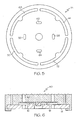
- Figure 1 is a schematic, cross-sectional view of a first embodiment of the invention showing an MR piston together with an attached piston rod and surrounding cylinder which together at least partially define an MR damper;
- Figure 2 is a longitudinal head-on view of the distal end of the MR piston core removed from of the MR piston of figure 1 ;
- Figure 3 is a longitudinal head-on view of the distal end of the shim disc removed from the MR piston of figure 1 ;
- Figure 4 is a longitudinal head-on view of the distal end of the orifice disc removed from the MR piston of figure 1 ;
- Figure 5 is a longitudinal head-on view of the distal end of the MR piston end plate removed from the MR piston of figure 1 ;
- Figure 6 is a schematic, cross-sectional view of a second embodiment of the invention showing a portion of an MR piston including an MR piston end plate, a shim disc, an orifice disc, and a portion of an MR piston core.
- FIG. 1-5 shows an embodiment of the present invention.
- a first expression of the embodiment of figures 1-5 is for a magnetorheological (MR) piston 10 including an MR piston core 12, an MR piston end plate 14, a shim disc 16, and a flexible orifice disc 18.
- the MR piston core 12 includes an end 20 and includes a bypass passageway (i.e., a magnetically non-energizable passageway) 22.
- the MR piston end plate 14 covers the end 20 to define a chamber 24 between the end 20 and the MR piston end plate 14 and has a through passageway 26 aligned with the bypass passageway 22 at the chamber 24.
- the shim disc 16 is positioned in the chamber 24 apart from the bypass and through passageways 22 and 26.
- the orifice disc 18 is positioned in the chamber 24, faces the shim disc 16, extends past the shim disc 16 and the bypass passageway 22, includes an orifice (sometimes called a standard orifice) 28 aligned with the bypass passageway 22 at the chamber 24, and includes an additional orifice 30.
- Under fluid pressure in a first direction 32 the orifice disc 18 lies substantially flat against one of the end 20 and the MR piston end plate 14 allowing fluid communication between the bypass passageway 22 and the through passageway 26 by way of the orifice 28 but not by way of the additional orifice 30.
- the orifice disc 18 Under fluid pressure in an opposite second direction 34 the orifice disc 18 is deflected by the presence of the shim disc 16 to lift the additional orifice 30 from the one of the end 20 and the MR piston end plate 14 allowing fluid communication between the bypass passageway 22 and the through passageway 26 by way of the orifice 28 and by way of the additional orifice 30.
- aligned means substantially aligned, and that the phrase “shim disc” includes a stack of shim discs and the phrase “orifice disc” includes a stack of orifice discs.
- the MR piston 10 also includes an electric coil 36 and a magnetically energizable passageway (i.e., an MR passageway) 38 , wherein the electric coil 36 is disposed in the MR piston core 12.
- the MR piston 10 includes an MR piston ring 40, wherein the MR piston core 12 has a central longitudinal axis 42 and wherein the MR piston ring 40 is attached to the MR piston end plate 14 and is radially spaced apart from the MR piston core 12 to define the magnetically energizable passageway 38.
- the electric coil 36 is spaced radially between the bypass passageway 22 and the magnetically energizable passageway 38 and proximate the magnetically energizable passageway 38.
- the MR piston end plate 14 includes a through opening 44 in fluid communication with the magnetically energizable passageway 38.
- the MR piston core 12 has a central longitudinal axis 42, and the shim disc 16 and the orifice disc 18 are coaxially aligned with the longitudinal axis 42.
- a second expression of the embodiment of figures 1-5 is for a magnetorheological (MR) piston 10 including an MR piston core 12, an MR piston end plate 14, a shim disc 16, and a flexible orifice disc 18.
- the MR piston core 12 includes a central longitudinal axis 42, includes an end 20 having a recessed portion 46, and includes a longitudinally-extending bypass passageway 22 extending to the recessed portion 46.
- the MR piston end plate 14 is coaxially aligned with the longitudinal axis 42, covers the recessed portion 46 to define a chamber 24 between the recessed portion 46 and the MR piston end plate 14, and has a longitudinally-extending through passageway 26 aligned with the bypass passageway 22.
- the shim disc 16 is coaxially aligned with the longitudinal axis 42, is positioned in the chamber 24 radially inwardly apart from the bypass passageway 22, and is positioned proximate the recessed portion 46.
- the orifice disc 18 is coaxially aligned with the longitudinal axis 42, is positioned in the chamber 24, is positioned proximate the shim disc 16 and the MR piston end plate 14, extends radially outwardly past the shim disc 16 and the bypass passageway 22, and includes an orifice 28 aligned with the bypass passageway 22.
- the orifice disc 18 also includes an additional orifice 30 disposed radially outward from the shim disc 16 and unaligned with any bypass passageway 22 of the MR piston core 12 and any through passageway 26 of the MR piston end plate 14.
- aligned means substantially aligned
- longitudinally-extending means substantially-longitudinally-extending
- shim disc includes a stack of shim discs
- orifice disc includes a stack of orifice discs.
- the MR piston core 12 includes an additional bypass passageway 48, wherein the MR piston end plate 14 includes an additional through passageway 50, wherein the additional through passageway 50 is aligned with the additional bypass passageway 48 but not with any additional orifice (such as additional orifice 30) of the orifice disc 18.
- the MR piston core 12 includes second and third additional bypass passageways 52 and 54
- the orifice disc 18 includes second, third and fourth additional orifices 56, 58 and 60
- the MR piston end plate 14 includes second and third additional through passageways 62 and 64.
- the MR piston 10 includes an additional, a second additional and a third additional magnetically-energizable passageway (only the additional magnetically-energizable passageway 66 is shown), and the MR piston end plate 14 includes an additional, a second additional and a third additional through opening 68, 70 and 72.
- the MR piston core 12 includes a rotational-alignment boss 74, wherein the shim disc 16 includes a corresponding rotational-alignment opening 76 and wherein the orifice disc 18 includes a corresponding rotational-alignment opening 78.
- the orifice 28 has a smaller cross section than the bypass and through passageways 22 and 26.
- the orifice (also known as a standard orifice) 28 has a smaller cross section than any of the additional orifices 30, 56, 58 and 60.
- the orifice disc 18 has one, two or three more standard orifices, not shown, aligned one each with a corresponding one of the additional bypass passageways 48, 52 and 54. In the same or a different arrangement, the shim disc 16 abuts the recessed portion 46, and the orifice disc 18 abuts the shim disc 16 and the MR piston end plate 14.
- the MR piston 10 includes an additional MR piston end plate 80 for the other end of the MR piston core 12. It is noted that an additional expression of the embodiment of figures 1-5 is for an MR piston assembly 82 which includes the MR piston 10 and a piston rod 84 which is attached to the MR piston 10. It is also noted that a further expression of the embodiment of figures 1-5 is for an MR damper 86 which includes a cylinder 88 and the MR piston assembly 82, wherein the MR piston 10 is slidingly disposed within the cylinder 88.
- FIG 7 A second embodiment of the invention is shown in figure 7.
- An expression of the embodiment of figure 7 is for an MR piston 110 and is identical to the second expression of the embodiment of figures 1-5 except that the shim disc 16 is positioned proximate the MR piston end plate 14 and the orifice disc 18 is positioned proximate the shim disc 16 and the recessed portion 46.
- the size of the orifice 28, the number and size of the additional orifices 30, 56, 58 and 60, the thickness and flexibility of the orifice disc 18, and the diameter and thickness of the shim disc 16 are chosen to tune the MR piston 10 to create a desired asymmetric damping load by creating additional bypass flow paths which reduce on-state (i.e., the electric coil 36 is turned on) damping force in one piston direction.
- the additional bypass flow paths are created when the orifice disc 18 deflects which lifts the additional orifice(s). When the piston reverses in direction, the orifice disc flattens out and closes off the additional bypass flow paths.
- the magnetically-energizable passageways are similar in size and shape to, and are aligned with, the through openings 44, 68, 70 and 72 of the MR piston end plate 14 as seen in figure 5 .
- the MR piston is an MR piston of a vehicle MR suspension damper and is controlled by a vehicle electronic control unit in response to sensor inputs such as, without limitation, steering, braking, acceleration, and road condition sensor inputs.
- the additional orifice provides a different damper force depending on whether the MR damper is in jounce (compression) or rebound (extension) and reduces the undesirable effect of the lag time between a change in steering, braking, etc. and applying a changed current to the electric coil of the MR damper to effect damping in the MR passageway of the MR piston core.
- the additional orifice design should provide different damping for jounce and rebound at lower piston velocities and should provide, compared with a conventional tapered MR passageway design or a conventional externally-mounted apparatus, an increased difference in damping for jounce and rebound at higher piston velocities.
Landscapes
- Engineering & Computer Science (AREA)
- General Engineering & Computer Science (AREA)
- Physics & Mathematics (AREA)
- Electromagnetism (AREA)
- Mechanical Engineering (AREA)
- Fluid-Damping Devices (AREA)
Claims (11)
- Piston magnéto-rhéologique (MR) comprenant :a) un noyau de piston MR (12) comprenant une extrémité (20) et une voie de passage de contournement (22) etb) une plaque d'extrémité de piston MR (14) couvrant l'extrémité pour définir une chambre (24) entre l'extrémité et la plaque d'extrémité du piston MR et ayant une voie de passage traversante alignée sur la voie de passage de contournement (26) au niveau de la chambre, caractérisé parc) un disque de compensation (16) disposé dans la chambre, à distance des voies de passage de contournement et traversante,d) un disque souple à orifice (18) disposé dans la chambre, faisant face au disque de compensation, s'étendant au-delà de celui-ci et de la voie de passage traversante et comprenant un orifice (28) aligné sur la voie de passage traversante au niveau de la chambre, ainsi qu'un orifice additionnel, sous la pression du fluide dans une première direction, le disque à orifice étant situé essentiellement à plat contre une parmi l'extrémité et la plaque d'extrémité du piston MR permettant une communication fluidique entre la voie de passage de contournement et la voie de passage traversante par l'intermédiaire de l'orifice, mais non pas par l'intermédiaire de l'orifice additionnel et, sous la pression du fluide dans une seconde direction opposée, le disque à orifice étant dévié par la présence du disque de compensation pour lever l'orifice additionnel depuis l'une parmi l'extrémité et la plaque d'extrémité du piston MR permettant une communication fluidique entre la voie de passage de contournement et la voie de passage traversante par l'intermédiaire de l'orifice et par l'intermédiaire de l'orifice additionnel.
- Piston MR suivant la revendication 1 comprenant, en outre, une bobine électrique (36) et une voie de passage excitable magnétiquement (38), la bobine électrique étant disposée dans le noyau de piston MR (12).
- Piston MR suivant la revendication 2, comprenant, en outre, un segment de piston MR (40), le noyau de piston MR (12) présentant un axe longitudinal central et le segment de piston étant fixé à la plaque d'extrémité du piston MR (14) et disposé de façon espacé radialement vers l'extérieur par rapport au noyau de piston pour définir la voie de passage excitable magnétiquement (38).
- Piston MR suivant la revendication 3, dans lequel la bobine électrique (36) est disposée entre la voie de passage de contournement (22) et la voie de passage excitable magnétiquement (38), à proximité de celle-ci, voies de passage, par rapport auxquelles elle est espacée radialement.
- Piston MR suivant la revendication 1, dans lequel la plaque d'extrémité du piston MR (14) comprend une ouverture traversante (68, 70, 72) en communication fluidique avec la voie de passage excitable magnétiquement.
- Piston MR suivant la revendication 1, dans lequel le noyau du piston MR (12) présente un axe longitudinal central (42) et dans lequel le disque de compensation (16) et le disque à orifice (18) sont alignés, de façon coaxiale, sur l'axe longitudinal.
- Piston MR suivant la revendication 1 comprenant un disque souple à orifice (18) aligné, de façon coaxiale, sur l'axe longitudinal, disposé dans la chambre, disposé à proximité du disque de compensation et de la plaque d'extrémité du piston MR, s'étendant radialement vers l'extérieur au-delà du disque de compensation et de la voie de passage de contournement, et comprenant un orifice (28) aligné sur la voie de passage de contournement, le disque à orifice comprenant, en outre, un orifice additionnel disposé radialement vers l'extérieur par rapport au disque de compensation et de façon non alignée sur toute voie de passage de contournement du noyau du piston MR et sur toute voie de passage traversante de la plaque d'extrémité du piston MR.
- Piston MR suivant la revendication 1, dans lequel le noyau du piston MR comprend une voie de passage de contournement additionnelle, la plaque d'extrémité du piston MR comprenant une voie de passage traversante additionnelle, la voie de passage traversante additionnelle étant alignée sur la voie de passage de contournement additionnelle, mais non pas sur tout orifice additionnel du disque à orifice.
- Piston MR suivant la revendication 1, dans lequel l'orifice présente une section transversale plus petite que les voies de passage de contournement et traversante.
- Piston MR suivant la revendication 1, dans lequel le disque de compensation vient buter contre la portion en retrait et dans lequel le disque à orifice vient buter contre le disque de compensation et la plaque d'extrémité du piston MR.
- Piston MR suivant la revendication 1 comprenant un disque souple à orifice (18) aligné, de façon coaxiale, sur l'axe longitudinal, disposé dans la chambre, disposé à proximité du disque de compensation et de la portion en retrait, s'étendant radialement vers l'extérieur au-delà du disque de compensation et de la voie de passage de contournement et comprenant un orifice (28) aligné sur la voie de passage traversante, le disque à orifice comprenant, en outre, un orifice additionnel disposé radialement vers l'extérieur par rapport au disque de compensation et de façon non alignée sur toute voie de passage de contournement du noyau du piston MR et sur toute voie de passage traversante de la plaque d'extrémité du piston MR.
Applications Claiming Priority (1)
| Application Number | Priority Date | Filing Date | Title |
|---|---|---|---|
| US11/820,812 US7753180B2 (en) | 2007-06-20 | 2007-06-20 | Magnetorheological piston having a bypass passageway |
Publications (3)
| Publication Number | Publication Date |
|---|---|
| EP2006568A2 EP2006568A2 (fr) | 2008-12-24 |
| EP2006568A3 EP2006568A3 (fr) | 2012-05-30 |
| EP2006568B1 true EP2006568B1 (fr) | 2014-09-03 |
Family
ID=39776585
Family Applications (1)
| Application Number | Title | Priority Date | Filing Date |
|---|---|---|---|
| EP08156907.1A Active EP2006568B1 (fr) | 2007-06-20 | 2008-05-26 | Piston magnétorhéologique ayant un passage de dérivation |
Country Status (2)
| Country | Link |
|---|---|
| US (1) | US7753180B2 (fr) |
| EP (1) | EP2006568B1 (fr) |
Families Citing this family (6)
| Publication number | Priority date | Publication date | Assignee | Title |
|---|---|---|---|---|
| KR100892999B1 (ko) * | 2007-09-17 | 2009-04-10 | 에스앤티대우(주) | 연속 감쇠력 가변형 댐퍼의 피스톤밸브 어셈블리 |
| JP5865801B2 (ja) * | 2012-08-06 | 2016-02-17 | Kyb株式会社 | 磁気粘性流体緩衝器 |
| CN105156566A (zh) * | 2015-07-20 | 2015-12-16 | 常州大学 | 双杆多级绕射有源双控变阻尼磁流变阻尼器 |
| CN105065554A (zh) * | 2015-07-20 | 2015-11-18 | 常州大学 | 单杆多级绕射有源单控变阻尼磁流变阻尼器 |
| CN105041955A (zh) * | 2015-07-20 | 2015-11-11 | 常州大学 | 双杆多级绕射无源单控变阻尼磁流变阻尼器 |
| US10247272B2 (en) | 2016-08-05 | 2019-04-02 | Beijingwest Industries Co., Ltd. | Hydraulic damper having self-adjusting wear band |
Family Cites Families (8)
| Publication number | Priority date | Publication date | Assignee | Title |
|---|---|---|---|---|
| FR1400623A (fr) * | 1964-05-04 | 1965-05-28 | Pullman Inc | Amortisseur hydraulique de chocs à course de grande longueur |
| GB2126687B (en) * | 1982-07-14 | 1986-08-20 | Tokico Ltd | Hydraulic damper with adjustable damping force |
| US6095486A (en) * | 1997-03-05 | 2000-08-01 | Lord Corporation | Two-way magnetorheological fluid valve assembly and devices utilizing same |
| US6419058B1 (en) * | 2001-03-30 | 2002-07-16 | Delphi Technologies, Inc. | Magnetorheological damper with piston bypass |
| US20030000781A1 (en) | 2001-06-28 | 2003-01-02 | Delphi Technologies, Inc. | Magnetorheological damper piston with bypass valving |
| US6637557B2 (en) * | 2001-08-13 | 2003-10-28 | Delphi Technologies, Inc. | Magnetorheological strut piston with compression bypass |
| US20040118646A1 (en) * | 2002-12-23 | 2004-06-24 | Delphi Technologies Inc | Magnetorheological damper assembly and piston |
| KR20070103858A (ko) * | 2006-04-20 | 2007-10-25 | 현대모비스 주식회사 | 차량의 전자제어 현가장치용 페일 세이프 타입 엠알 씨디씨댐퍼 |
-
2007
- 2007-06-20 US US11/820,812 patent/US7753180B2/en active Active
-
2008
- 2008-05-26 EP EP08156907.1A patent/EP2006568B1/fr active Active
Also Published As
| Publication number | Publication date |
|---|---|
| US20080314705A1 (en) | 2008-12-25 |
| EP2006568A3 (fr) | 2012-05-30 |
| US7753180B2 (en) | 2010-07-13 |
| EP2006568A2 (fr) | 2008-12-24 |
Similar Documents
| Publication | Publication Date | Title |
|---|---|---|
| EP2037150B1 (fr) | Piston magnéto-rhéologique (MR), ensemble de piston MR et système d'amortisseur MR | |
| EP2006568B1 (fr) | Piston magnétorhéologique ayant un passage de dérivation | |
| US7694785B2 (en) | Controllable damping force hydraulic shock absorber | |
| JP5812650B2 (ja) | 減衰力調整式緩衝器 | |
| EP1983213B1 (fr) | Absorbeur de chocs à pression fluide réglable de force d'amortissement | |
| JP5685592B2 (ja) | 自動車のショックアブソーバ | |
| US6668986B2 (en) | Active hydraulic fluid vehicular suspension damper | |
| EP1437526B1 (fr) | Piston et amortisseur magnétorhéologique | |
| EP2828547B1 (fr) | Amortisseur hydraulique sensible à l'amplitude | |
| WO2011043928A2 (fr) | Amortisseur à soupape numérique | |
| US11280380B2 (en) | Magnetorheological hydraulic damper with passive damping chamber | |
| EP1588072B1 (fr) | Soupape integree de reglage de l'amortissement | |
| ITTO20090681A1 (it) | Valvola passiva di controllo del flusso e ammortizzatore a smorzamento regolabile comprendente tale valvola | |
| EP1566562B1 (fr) | Amortisseur de suspension hydraulique | |
| US9366270B2 (en) | Damping valve arrangement for a semiactive vibration damper | |
| EP2828546A1 (fr) | Amortisseur hydraulique avec ensemble soupape réglable de rebond | |
| WO2014024765A1 (fr) | Soupape et amortisseur | |
| CN114076166A (zh) | 包括流体室中的吸入阀的阻尼器组件 | |
| EP2128484B1 (fr) | Amortisseur hydraulique équipé d'un ensemble de chambre supplémentaire et procédé d'ajustement d'une caractéristique d'amortissement d'un tel amortisseur | |
| US20170313355A1 (en) | Controllable shock absorber for motor vehicles | |
| EP1270989B1 (fr) | Amortisseur à fluide magnétorhéologique avec de multiples passages annulaires | |
| CN112360913B (zh) | 液压阻尼器和用于液压阻尼器组件的活塞 | |
| US11305604B2 (en) | Vibration damper and vehicle | |
| EP2601425B1 (fr) | Piston pour amortisseur à amortissement réglable, en particulier pour une suspension de véhicule, comprenant quatre soupapes passives de commande de d'écoulement et une électrovanne divisant l'écoulement | |
| EP4357637A1 (fr) | Ensemble amortisseur comprenant une soupape d'admission dans une chambre de fluide |
Legal Events
| Date | Code | Title | Description |
|---|---|---|---|
| PUAI | Public reference made under article 153(3) epc to a published international application that has entered the european phase |
Free format text: ORIGINAL CODE: 0009012 |
|
| AK | Designated contracting states |
Kind code of ref document: A2 Designated state(s): AT BE BG CH CY CZ DE DK EE ES FI FR GB GR HR HU IE IS IT LI LT LU LV MC MT NL NO PL PT RO SE SI SK TR |
|
| AX | Request for extension of the european patent |
Extension state: AL BA MK RS |
|
| RAP1 | Party data changed (applicant data changed or rights of an application transferred) |
Owner name: BWI COMPANY LIMITED S.A. |
|
| PUAL | Search report despatched |
Free format text: ORIGINAL CODE: 0009013 |
|
| AK | Designated contracting states |
Kind code of ref document: A3 Designated state(s): AT BE BG CH CY CZ DE DK EE ES FI FR GB GR HR HU IE IS IT LI LT LU LV MC MT NL NO PL PT RO SE SI SK TR |
|
| AX | Request for extension of the european patent |
Extension state: AL BA MK RS |
|
| RIC1 | Information provided on ipc code assigned before grant |
Ipc: F16F 9/53 20060101AFI20120425BHEP |
|
| 17P | Request for examination filed |
Effective date: 20121127 |
|
| AKX | Designation fees paid |
Designated state(s): DE FR GB |
|
| GRAP | Despatch of communication of intention to grant a patent |
Free format text: ORIGINAL CODE: EPIDOSNIGR1 |
|
| INTG | Intention to grant announced |
Effective date: 20140430 |
|
| GRAS | Grant fee paid |
Free format text: ORIGINAL CODE: EPIDOSNIGR3 |
|
| GRAA | (expected) grant |
Free format text: ORIGINAL CODE: 0009210 |
|
| AK | Designated contracting states |
Kind code of ref document: B1 Designated state(s): DE FR GB |
|
| REG | Reference to a national code |
Ref country code: GB Ref legal event code: FG4D |
|
| REG | Reference to a national code |
Ref country code: DE Ref legal event code: R096 Ref document number: 602008034180 Country of ref document: DE Effective date: 20141016 |
|
| REG | Reference to a national code |
Ref country code: DE Ref legal event code: R097 Ref document number: 602008034180 Country of ref document: DE |
|
| PLBE | No opposition filed within time limit |
Free format text: ORIGINAL CODE: 0009261 |
|
| STAA | Information on the status of an ep patent application or granted ep patent |
Free format text: STATUS: NO OPPOSITION FILED WITHIN TIME LIMIT |
|
| 26N | No opposition filed |
Effective date: 20150604 |
|
| REG | Reference to a national code |
Ref country code: FR Ref legal event code: PLFP Year of fee payment: 9 |
|
| REG | Reference to a national code |
Ref country code: FR Ref legal event code: PLFP Year of fee payment: 10 |
|
| REG | Reference to a national code |
Ref country code: FR Ref legal event code: PLFP Year of fee payment: 11 |
|
| REG | Reference to a national code |
Ref country code: FR Ref legal event code: PLFP Year of fee payment: 16 |
|
| PGFP | Annual fee paid to national office [announced via postgrant information from national office to epo] |
Ref country code: GB Payment date: 20240404 Year of fee payment: 17 |
|
| PGFP | Annual fee paid to national office [announced via postgrant information from national office to epo] |
Ref country code: DE Payment date: 20240403 Year of fee payment: 17 |
|
| PGFP | Annual fee paid to national office [announced via postgrant information from national office to epo] |
Ref country code: FR Payment date: 20240408 Year of fee payment: 17 |