EP2006469A2 - Vorrichtung zum Einspritzen einer Kügelchenisolierung - Google Patents
Vorrichtung zum Einspritzen einer Kügelchenisolierung Download PDFInfo
- Publication number
- EP2006469A2 EP2006469A2 EP08011008A EP08011008A EP2006469A2 EP 2006469 A2 EP2006469 A2 EP 2006469A2 EP 08011008 A EP08011008 A EP 08011008A EP 08011008 A EP08011008 A EP 08011008A EP 2006469 A2 EP2006469 A2 EP 2006469A2
- Authority
- EP
- European Patent Office
- Prior art keywords
- pump
- bead insulation
- dispensing head
- bead
- adhesive
- Prior art date
- Legal status (The legal status is an assumption and is not a legal conclusion. Google has not performed a legal analysis and makes no representation as to the accuracy of the status listed.)
- Granted
Links
Images
Classifications
-
- E—FIXED CONSTRUCTIONS
- E04—BUILDING
- E04F—FINISHING WORK ON BUILDINGS, e.g. STAIRS, FLOORS
- E04F21/00—Implements for finishing work on buildings
- E04F21/02—Implements for finishing work on buildings for applying plasticised masses to surfaces, e.g. plastering walls
- E04F21/06—Implements for applying plaster, insulating material, or the like
- E04F21/08—Mechanical implements
- E04F21/085—Mechanical implements for filling building cavity walls with insulating materials
-
- B—PERFORMING OPERATIONS; TRANSPORTING
- B05—SPRAYING OR ATOMISING IN GENERAL; APPLYING FLUENT MATERIALS TO SURFACES, IN GENERAL
- B05B—SPRAYING APPARATUS; ATOMISING APPARATUS; NOZZLES
- B05B7/00—Spraying apparatus for discharge of liquids or other fluent materials from two or more sources, e.g. of liquid and air, of powder and gas
- B05B7/14—Spraying apparatus for discharge of liquids or other fluent materials from two or more sources, e.g. of liquid and air, of powder and gas designed for spraying particulate materials
- B05B7/1481—Spray pistols or apparatus for discharging particulate material
- B05B7/149—Spray pistols or apparatus for discharging particulate material with separate inlets for a particulate material and a liquid to be sprayed
Definitions
- This invention relates to apparatus for injecting bead insulation, especially adhesive bonded bead insulation.
- This system is disadvantageous due to the noise of the compressed air equipment, which typically exceeds 80 dB and, as such, creates a difficult working environment and may exceed legal noise limits.
- the conventional system requires at least two operatives to control the operation, namely one operative for holding the gun and a second operative to control the air compressor and the supply bead insulation.
- the force created by the compressed air can damage the beads and the adhesive, and can make the conventional apparatus unsuitable for filling all types of cavities.
- the compressed air has the effect of reducing the operating temperature of the system by about 5°, which, on cold days, can cause the bead/adhesive to freeze and jam in the gun.
- the compressed air equipment tends to be heavy and so is difficult to transport and manoeuvre.
- An apparatus for injecting bead insulation comprising a pump and a dispensing head, the pump having an inlet in fluid communication, during use, with a source of bead insulation, typically dry bead insulation, and an outlet in fluid communication with the dispensing head, wherein the pump is arranged to draw bead insulation from said source into said pump, and to pump said drawn bead insulation to said dispensing head.
- the apparatus includes, or is connectable to, a source of adhesive, the apparatus further including means for introducing said adhesive into said bead insulation.
- the dispensing head includes a mixing chamber, arranged to receive bead insulation from said pump and adhesive from said adhesive source.
- said pump includes an impellor housed in a chamber.
- the impellor draws bead insulation into the chamber through an axial inlet and expels it from the chamber via a tangential outlet.
- a first buffer device e.g. in the form of a blow box, is provided between the pump and the source of bead insulation.
- the buffer device is arranged to provide a buffer storage area for bead insulation.
- the buffer device has an outlet connected (directly or indirectly) to the pump, and an inlet connected (directly or indirectly to the bead insulation source, the outlet being located in use above the inlet.
- a second buffer device is provided between the pump and the dispensing head.
- the buffer device is arranged to provide a buffer storage area for bead insulation.
- the second buffer device takes the form of a section of conduit with a relatively large width connected to the outlet of the pump.
- the present invention provides an apparatus for injecting bead insulation into a cavity between two skins of a cavity wall, the apparatus comprising a pump, preferably a centrifugal pump, having a chamber with, preferably, an axial inlet and a tangential outlet, the outlet being in piped communication with a gun and the inlet being in piped communication with a supply of dry bead insulation, the chamber housing an impellor driven by power means, and means being provided to introduce adhesive into the flow of bead insulation prior to discharge into a cavity.
- a pump preferably a centrifugal pump, having a chamber with, preferably, an axial inlet and a tangential outlet, the outlet being in piped communication with a gun and the inlet being in piped communication with a supply of dry bead insulation
- the chamber housing an impellor driven by power means, and means being provided to introduce adhesive into the flow of bead insulation prior to discharge into a cavity.
- the apparatus is particularly suited for injecting insulation between two skins of a cavity wall.
- Each skin may be formed by building using brick and/or block, or the wall may be formed from an inner skin of natural or composite wood panelling and an outer skin of brick or block, or the wall may be formed of two skins of natural or composite wood panelling.
- the wood panelling may alternatively be substituted by panelling of any other suitable material, for example glass reinforced plastics material (GRP).
- GRP glass reinforced plastics material
- a blow box is desirably provided between the bead supply and the axial inlet.
- the blow box beneficially has an inlet at or near to its bottom and an outlet at or near to its top, the outlet preferably being at right angles to the inlet.
- a butterfly valve is provided to adjust the speed of flow of bead insulation passing into the pump.
- the valve is desirably positioned at or near to the top of the blow box, for example in a release port parallel to the inlet.
- the apparatus is preferably mountable on a rear part of a box van with the remaining part, forward thereof, being a reservoir for holding the main supply of bead insulation.
- said introducing means comprises a supply of adhesive held in the pressure vessel and piped therefrom to the gun.
- the invention provides a method of injecting bead insulation in an apparatus comprising a pump and a dispensing head, the pump having an inlet in fluid communication, during use, with a source of bead insulation, typically dry bead insulation, and an outlet in fluid communication with the dispensing head, the method comprising drawing bead insulation from said source into said pump, and pumping said drawn bead insulation to said dispensing head.
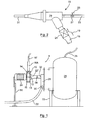
- the apparatus 5 is particularly suited for injecting bead insulation, especially bonded bead insulation, into a cavity between two skins of a cavity wall (not shown).
- the apparatus 5 in the preferred embodiment comprises a pump 10, preferably a centrifugal pump, having a chamber 11 with an axial inlet 12 and a tangential outlet 14.
- the outlet 14 is in fluid communication with a dispensing head, in the preferred form of an injection gun 18, by means of a conduit 16, e.g. a hose, pipe, duct or other means for conveying bead insulation.
- the inlet 12 is in fluid communication with a supply of dry bead insulation (not shown) by means of a conduit 22, e.g. a hose, pipe, duct or other means for conveying bead insulation, and, preferably, a buffer device in the form of a blow box 28.
- the chamber 11 houses an impellor 13, or fan, driven, in use, by power means, conveniently in the form of an electric motor 24.
- the gun 18 has a first operating mechanism 19 for controlling a valve 21 which in turn controls the delivery of bead insulation from the pump 10 to the gun 18.
- a supply of adhesive is provided in a pressurized vessel 26.
- a conduit 23 e.g. a pipe or hose duct or other means for conveying adhesive, is provided between the pressurized vessel 26 and the gun 18 for delivering adhesive to the gun 18.
- the gun 18 has a second operating mechanism 25 for controlling a valve 27 which, in turn, controls the flow of adhesive from the vessel 26 to the gun 18.
- the adhesive is typically liquid in form.
- the pressure vessel 26 may be omitted and the gun 18 may be connected to a pumped source of adhesive (not shown), e.g. an adhesive reservoir provided with a pump for delivering the adhesive to the gun 18.
- a pumped source of adhesive e.g. an adhesive reservoir provided with a pump for delivering the adhesive to the gun 18.
- the flow of adhesive to the gun may still be controlled by the valve 27 and operating mechanism 25.
- the gun 18 has a mixing chamber 29 in which the bead insulation and adhesive are mixed before being dispensed from the nozzle 31 of the gun 18.
- the gun 18 is operable by a single operator (not shown) by means of the operating mechanisms 19, 25. Hence, a single operator is able to control the operation of the apparatus 5.
- the blow box 28 is provided between the bead supply and pump 10.
- the blow box 28 has an inlet 30, which may for example be located at or near to its bottom, and an outlet 32 preferably located at or near to its top.
- the inlet 30 is connected to the conduit 22 to receive bead insulation during use.
- the outlet 32 is connected to the pump 10, in particular to the inlet 12 of the pump 10, by any suitable means, for example a pipe section 22'.
- a valve 34 is provided to adjust the speed of flow of bead insulation passing into the pump 10.
- the valve 34 which may for example comprise a butterfly valve, may be positioned at or near to the top of the blow box 28, but is preferably provided in the pipe section 22', i.e. between the blow box 28 and the pump 10.
- the valve 34 is arranged to control the flow of air from the environment into the flow of bead insulation.
- the setting of the valve 34 may be adjusted depending on the distance that the bead has to travel before it is dispensed by the gun 18. For longer distances, the valve 34 may be set to increase the flow of air into the system since this helps carry the bead insulation further.
- the blow box 28 comprises a chamber located in the path of the bead insulation between the bead supply and the pump 10.
- the blow box 28 is typically box like in form, e.g. being of substantially rectangular cross section, but may take any other suitable form. For example, it may take the form of a section of conduit (not illustrated), preferably having a bore that is wider than the bore of the conduit 22 that feeds into it.
- the outlet 32 is preferably located substantially at the, in use, top of the box 20 (and therefore at the top of the chamber) and is typically arranged to be above, in use, the inlet 30.
- any bead insulation that is located in the blow box 28, or is introduced into the blow box 28, during the time in which the motor 24 is switched off and the impellor is running down, will tend together, under gravity, in the chamber of the blow box 28.
- the blow box 28 therefore acts as a buffer between the bead supply and the pump 10.
- the conduit 16 includes a buffer portion 16A adjacent the pump 10. Conveniently, this is provided by a section of the conduit 16 being of larger diameter than the subsequent section of the conduit 16', although may take any other suitable form. Preferably, the transition between the buffer section 16A and the subsequent section 16' takes the form of a funnel.
- the conduit 16 may have a diameter of approximately 38 mm, while the buffer section 16A has a diameter of approximately 75 mm.
- the buffer section 16A provides a space in which bead insulation, which would otherwise be held in the chamber 11, to leave the chamber 11 and be stored in the buffer section 16A. This reduces the chance that the bead insulation will jam the impellor 13.
- the volume of the buffer section 16A is at least equal to the volume of the chamber 11.
- the valve 34 may be opened to increase the flow of air into the conduit 22'. This has the effect of reducing the quantity of bead being inducted into the conduit 22' from the blow box 28 while providing an increased quantity of air to assist in expelling bead from the chamber 11.
- the impellor may be arranged to rotate at approximately 1,500 rpm during normal use.
- the diameter of the impellor may, for example, be in the region of 20 to 40cms.
- the apparatus 5 is mounted between two stands 51 and 53.
- the pressure vessel 26 may conveniently also be mounted to the stand 53.
- the apparatus 5 is capable of injecting bead insulation at pressures that are less than would normally be achieved using a compressed air system. As a result, the apparatus 5 is capable of injecting insulation into relatively fragile structures, for example the inter-leaf cavities of a timber framed building structure.
- the supply of bead insulation may be provided in any suitable container, for example, a stand-alone silo, or a container or compartment located in the payload area of a van, or any other suitable container.
- the container includes an air inlet, or at least is not air tight, to allow the pump 10 to create a flow of air by which the bead may be drawn to the pump 10 and then expelled to the gun 18.
- bead insulation is drawn into the pump 10 via the conduit 22, blow box 28 and pipe section 22', from the bead supply.
- the bead insulation enters the chamber 11 via inlet 12 and, under the action of the impellor 13, and is driven out of the chamber 11 via outlet 14.
- the bead insulation is then conveyed to the gun 18 via the conduit 16.
- the adhesive is also supplied to the gun, under pressure, from the pressurised tank 26 via conduit 23.
- the operator is able to cause the adhesive and the bead insulation to mix in the mixing chamber 29 and subsequently to be dispensed via the nozzle 31.
- the adhesive may comprise any suitable bead adhesive or other bonding agent and is typically liquid in form.
- the bead insulation may comprise beads formed from polystyrene or other thermally insulating material, especially expandable polystyrene (containing an expanding agent, for example, pentane), or foamed plastics particles.
- the apparatus 5 is relatively compact, and so is amenable to being mounted on a rear part of a van, e.g. a box van (not shown) with the remaining part of the van, forward thereof, being or carrying a reservoir for holding the main supply of bead insulation.
- a van e.g. a box van (not shown) with the remaining part of the van, forward thereof, being or carrying a reservoir for holding the main supply of bead insulation.
- the van may be, for example, a 3.5 tonne vehicle rather than, say, a lorry of 7.5 tonne, in which case driver restrictions due to HGV grade requirements are obviated.
Landscapes
- Engineering & Computer Science (AREA)
- Architecture (AREA)
- Civil Engineering (AREA)
- Structural Engineering (AREA)
- Coating Apparatus (AREA)
- Application Of Or Painting With Fluid Materials (AREA)
Applications Claiming Priority (1)
| Application Number | Priority Date | Filing Date | Title |
|---|---|---|---|
| GBGB0711756.7A GB0711756D0 (en) | 2007-06-18 | 2007-06-18 | Apparatus for injecting bead insulation |
Publications (3)
| Publication Number | Publication Date |
|---|---|
| EP2006469A2 true EP2006469A2 (de) | 2008-12-24 |
| EP2006469A3 EP2006469A3 (de) | 2009-05-06 |
| EP2006469B1 EP2006469B1 (de) | 2016-08-24 |
Family
ID=38332297
Family Applications (1)
| Application Number | Title | Priority Date | Filing Date |
|---|---|---|---|
| EP08011008.3A Active EP2006469B1 (de) | 2007-06-18 | 2008-06-18 | Vorrichtung zum Einspritzen einer Kügelchenisolierung |
Country Status (2)
| Country | Link |
|---|---|
| EP (1) | EP2006469B1 (de) |
| GB (1) | GB0711756D0 (de) |
Cited By (2)
| Publication number | Priority date | Publication date | Assignee | Title |
|---|---|---|---|---|
| CN111173236A (zh) * | 2020-01-13 | 2020-05-19 | 上海家倍得装饰工程有限公司 | 一种家装用便携式喷涂装置 |
| US20240218678A1 (en) * | 2022-12-30 | 2024-07-04 | Certainteed Llc | Connector Modules for Loose Fill Insulation Hose and Method of Installing Loose Fill Insulation |
Citations (1)
| Publication number | Priority date | Publication date | Assignee | Title |
|---|---|---|---|---|
| BE380374A (de) |
Family Cites Families (8)
| Publication number | Priority date | Publication date | Assignee | Title |
|---|---|---|---|---|
| US2235542A (en) * | 1937-08-24 | 1941-03-18 | Wenzel Amanda | Building insulation |
| US3223329A (en) * | 1962-01-16 | 1965-12-14 | Ronald A Ross | Flocking apparatus |
| NL182975C (nl) * | 1977-09-02 | 1988-06-16 | Shell Int Research | Aanvoerstuk voor warmte-isolerend materiaal. |
| US4151962A (en) * | 1977-12-29 | 1979-05-01 | Calhoun Thomas M | Apparatus for shredding and blowing foam plastic in place |
| FR2538829A1 (fr) * | 1982-12-29 | 1984-07-06 | S E R A H Sarl | Mur comportant une couche isolante, methode pour la fabriquer et appareil pour la mettre en oeuvre |
| US4768710A (en) * | 1987-03-02 | 1988-09-06 | Henry Sperber | Fibrous blown-in insulation having homogenous density |
| US20040124262A1 (en) * | 2002-12-31 | 2004-07-01 | Bowman David James | Apparatus for installation of loose fill insulation |
| AU2005223454A1 (en) * | 2004-03-18 | 2005-09-29 | Johns Manville | System and method for forming an insulation particle/air suspension |
-
2007
- 2007-06-18 GB GBGB0711756.7A patent/GB0711756D0/en not_active Ceased
-
2008
- 2008-06-18 EP EP08011008.3A patent/EP2006469B1/de active Active
Patent Citations (1)
| Publication number | Priority date | Publication date | Assignee | Title |
|---|---|---|---|---|
| BE380374A (de) |
Cited By (2)
| Publication number | Priority date | Publication date | Assignee | Title |
|---|---|---|---|---|
| CN111173236A (zh) * | 2020-01-13 | 2020-05-19 | 上海家倍得装饰工程有限公司 | 一种家装用便携式喷涂装置 |
| US20240218678A1 (en) * | 2022-12-30 | 2024-07-04 | Certainteed Llc | Connector Modules for Loose Fill Insulation Hose and Method of Installing Loose Fill Insulation |
Also Published As
| Publication number | Publication date |
|---|---|
| GB0711756D0 (en) | 2007-07-25 |
| EP2006469A3 (de) | 2009-05-06 |
| EP2006469B1 (de) | 2016-08-24 |
Similar Documents
| Publication | Publication Date | Title |
|---|---|---|
| US20100127476A1 (en) | Lightweight foamed concrete mixer | |
| US9421560B2 (en) | Method and apparatus to deliver a fluid mixture | |
| US4764536A (en) | Process and apparatus for the preparation of a free-flowing mixture made of free-flowing components which reacts to form foam | |
| US20030190200A1 (en) | Power weight or volumetric or counting feeder | |
| US4948054A (en) | Pneumatic drywall texture bazooka | |
| CN109420577B (zh) | 用于湿固化聚合物材料的计量和施加系统 | |
| AU2014277820B2 (en) | Aircraft water tank polymer gel preparation system | |
| EP2006469B1 (de) | Vorrichtung zum Einspritzen einer Kügelchenisolierung | |
| EP1123744B1 (de) | Spritzmaschine für Suspensionen | |
| KR102271066B1 (ko) | 포소화약제의 정량 비례 혼합이 가능한 비례혼합장치 | |
| JP5301325B2 (ja) | 消火装置 | |
| CN119075719A (zh) | 一种多模式混气装置 | |
| US7677414B2 (en) | Device for applying foamed hot melt adhesive, and method for selectively applying foamed hot melt adhesive and solid hot melt adhesive | |
| CN217354341U (zh) | 二氧化碳压裂加砂设备及石油机械 | |
| WO2006085656A1 (ja) | 発泡方法及びその装置 | |
| JP2001200699A (ja) | フレッシュ混練材料吹付けシステム | |
| JP2000117161A (ja) | 小形発泡散布装置 | |
| CA2824652C (en) | Method and apparatus for application of mortar | |
| EP4696420A1 (de) | Vorrichtung zum einspritzen von teilchenförmigem isolierstoff | |
| US12337202B2 (en) | Method and liquid mixing system for providing a liquid/foam mixture | |
| CN217047045U (zh) | 一种聚氨酯双组分发泡机混合装置 | |
| CN114673478A (zh) | 二氧化碳压裂加砂设备及加砂系统、加砂方法 | |
| US20060087910A1 (en) | Water injection method and apparatus for concrete mixer | |
| US20240286093A1 (en) | Self-contained device for generating a viscous foam | |
| EP2658614B1 (de) | Verfahren zum betrieb eines brandlöschsystems mit dualer verwendung einer gasquelle |
Legal Events
| Date | Code | Title | Description |
|---|---|---|---|
| PUAI | Public reference made under article 153(3) epc to a published international application that has entered the european phase |
Free format text: ORIGINAL CODE: 0009012 |
|
| AK | Designated contracting states |
Kind code of ref document: A2 Designated state(s): AT BE BG CH CY CZ DE DK EE ES FI FR GB GR HR HU IE IS IT LI LT LU LV MC MT NL NO PL PT RO SE SI SK TR |
|
| AX | Request for extension of the european patent |
Extension state: AL BA MK RS |
|
| PUAL | Search report despatched |
Free format text: ORIGINAL CODE: 0009013 |
|
| AK | Designated contracting states |
Kind code of ref document: A3 Designated state(s): AT BE BG CH CY CZ DE DK EE ES FI FR GB GR HR HU IE IS IT LI LT LU LV MC MT NL NO PL PT RO SE SI SK TR |
|
| AX | Request for extension of the european patent |
Extension state: AL BA MK RS |
|
| RIC1 | Information provided on ipc code assigned before grant |
Ipc: B05B 7/14 20060101ALI20080904BHEP Ipc: E04F 21/08 20060101AFI20090327BHEP |
|
| 17P | Request for examination filed |
Effective date: 20091106 |
|
| 17Q | First examination report despatched |
Effective date: 20091217 |
|
| AKX | Designation fees paid |
Designated state(s): AT BE BG CH CY CZ DE DK EE ES FI FR GB GR HR HU IE IS IT LI LT LU LV MC MT NL NO PL PT RO SE SI SK TR |
|
| GRAP | Despatch of communication of intention to grant a patent |
Free format text: ORIGINAL CODE: EPIDOSNIGR1 |
|
| INTG | Intention to grant announced |
Effective date: 20160404 |
|
| GRAS | Grant fee paid |
Free format text: ORIGINAL CODE: EPIDOSNIGR3 |
|
| GRAA | (expected) grant |
Free format text: ORIGINAL CODE: 0009210 |
|
| AK | Designated contracting states |
Kind code of ref document: B1 Designated state(s): AT BE BG CH CY CZ DE DK EE ES FI FR GB GR HR HU IE IS IT LI LT LU LV MC MT NL NO PL PT RO SE SI SK TR |
|
| REG | Reference to a national code |
Ref country code: GB Ref legal event code: FG4D |
|
| REG | Reference to a national code |
Ref country code: CH Ref legal event code: EP |
|
| REG | Reference to a national code |
Ref country code: AT Ref legal event code: REF Ref document number: 823262 Country of ref document: AT Kind code of ref document: T Effective date: 20160915 |
|
| REG | Reference to a national code |
Ref country code: IE Ref legal event code: FG4D |
|
| REG | Reference to a national code |
Ref country code: DE Ref legal event code: R096 Ref document number: 602008045826 Country of ref document: DE |
|
| REG | Reference to a national code |
Ref country code: NL Ref legal event code: FP |
|
| REG | Reference to a national code |
Ref country code: LT Ref legal event code: MG4D |
|
| REG | Reference to a national code |
Ref country code: AT Ref legal event code: MK05 Ref document number: 823262 Country of ref document: AT Kind code of ref document: T Effective date: 20160824 |
|
| PG25 | Lapsed in a contracting state [announced via postgrant information from national office to epo] |
Ref country code: NO Free format text: LAPSE BECAUSE OF FAILURE TO SUBMIT A TRANSLATION OF THE DESCRIPTION OR TO PAY THE FEE WITHIN THE PRESCRIBED TIME-LIMIT Effective date: 20161124 Ref country code: HR Free format text: LAPSE BECAUSE OF FAILURE TO SUBMIT A TRANSLATION OF THE DESCRIPTION OR TO PAY THE FEE WITHIN THE PRESCRIBED TIME-LIMIT Effective date: 20160824 Ref country code: IT Free format text: LAPSE BECAUSE OF FAILURE TO SUBMIT A TRANSLATION OF THE DESCRIPTION OR TO PAY THE FEE WITHIN THE PRESCRIBED TIME-LIMIT Effective date: 20160824 Ref country code: LT Free format text: LAPSE BECAUSE OF FAILURE TO SUBMIT A TRANSLATION OF THE DESCRIPTION OR TO PAY THE FEE WITHIN THE PRESCRIBED TIME-LIMIT Effective date: 20160824 Ref country code: FI Free format text: LAPSE BECAUSE OF FAILURE TO SUBMIT A TRANSLATION OF THE DESCRIPTION OR TO PAY THE FEE WITHIN THE PRESCRIBED TIME-LIMIT Effective date: 20160824 |
|
| PG25 | Lapsed in a contracting state [announced via postgrant information from national office to epo] |
Ref country code: PT Free format text: LAPSE BECAUSE OF FAILURE TO SUBMIT A TRANSLATION OF THE DESCRIPTION OR TO PAY THE FEE WITHIN THE PRESCRIBED TIME-LIMIT Effective date: 20161226 Ref country code: AT Free format text: LAPSE BECAUSE OF FAILURE TO SUBMIT A TRANSLATION OF THE DESCRIPTION OR TO PAY THE FEE WITHIN THE PRESCRIBED TIME-LIMIT Effective date: 20160824 Ref country code: GR Free format text: LAPSE BECAUSE OF FAILURE TO SUBMIT A TRANSLATION OF THE DESCRIPTION OR TO PAY THE FEE WITHIN THE PRESCRIBED TIME-LIMIT Effective date: 20161125 Ref country code: LV Free format text: LAPSE BECAUSE OF FAILURE TO SUBMIT A TRANSLATION OF THE DESCRIPTION OR TO PAY THE FEE WITHIN THE PRESCRIBED TIME-LIMIT Effective date: 20160824 Ref country code: ES Free format text: LAPSE BECAUSE OF FAILURE TO SUBMIT A TRANSLATION OF THE DESCRIPTION OR TO PAY THE FEE WITHIN THE PRESCRIBED TIME-LIMIT Effective date: 20160824 Ref country code: SE Free format text: LAPSE BECAUSE OF FAILURE TO SUBMIT A TRANSLATION OF THE DESCRIPTION OR TO PAY THE FEE WITHIN THE PRESCRIBED TIME-LIMIT Effective date: 20160824 |
|
| PG25 | Lapsed in a contracting state [announced via postgrant information from national office to epo] |
Ref country code: RO Free format text: LAPSE BECAUSE OF FAILURE TO SUBMIT A TRANSLATION OF THE DESCRIPTION OR TO PAY THE FEE WITHIN THE PRESCRIBED TIME-LIMIT Effective date: 20160824 Ref country code: EE Free format text: LAPSE BECAUSE OF FAILURE TO SUBMIT A TRANSLATION OF THE DESCRIPTION OR TO PAY THE FEE WITHIN THE PRESCRIBED TIME-LIMIT Effective date: 20160824 |
|
| REG | Reference to a national code |
Ref country code: DE Ref legal event code: R097 Ref document number: 602008045826 Country of ref document: DE |
|
| PG25 | Lapsed in a contracting state [announced via postgrant information from national office to epo] |
Ref country code: BE Free format text: LAPSE BECAUSE OF FAILURE TO SUBMIT A TRANSLATION OF THE DESCRIPTION OR TO PAY THE FEE WITHIN THE PRESCRIBED TIME-LIMIT Effective date: 20160824 Ref country code: DK Free format text: LAPSE BECAUSE OF FAILURE TO SUBMIT A TRANSLATION OF THE DESCRIPTION OR TO PAY THE FEE WITHIN THE PRESCRIBED TIME-LIMIT Effective date: 20160824 Ref country code: SK Free format text: LAPSE BECAUSE OF FAILURE TO SUBMIT A TRANSLATION OF THE DESCRIPTION OR TO PAY THE FEE WITHIN THE PRESCRIBED TIME-LIMIT Effective date: 20160824 Ref country code: CZ Free format text: LAPSE BECAUSE OF FAILURE TO SUBMIT A TRANSLATION OF THE DESCRIPTION OR TO PAY THE FEE WITHIN THE PRESCRIBED TIME-LIMIT Effective date: 20160824 Ref country code: PL Free format text: LAPSE BECAUSE OF FAILURE TO SUBMIT A TRANSLATION OF THE DESCRIPTION OR TO PAY THE FEE WITHIN THE PRESCRIBED TIME-LIMIT Effective date: 20160824 Ref country code: BG Free format text: LAPSE BECAUSE OF FAILURE TO SUBMIT A TRANSLATION OF THE DESCRIPTION OR TO PAY THE FEE WITHIN THE PRESCRIBED TIME-LIMIT Effective date: 20161124 |
|
| PLBE | No opposition filed within time limit |
Free format text: ORIGINAL CODE: 0009261 |
|
| STAA | Information on the status of an ep patent application or granted ep patent |
Free format text: STATUS: NO OPPOSITION FILED WITHIN TIME LIMIT |
|
| 26N | No opposition filed |
Effective date: 20170526 |
|
| PG25 | Lapsed in a contracting state [announced via postgrant information from national office to epo] |
Ref country code: SI Free format text: LAPSE BECAUSE OF FAILURE TO SUBMIT A TRANSLATION OF THE DESCRIPTION OR TO PAY THE FEE WITHIN THE PRESCRIBED TIME-LIMIT Effective date: 20160824 |
|
| REG | Reference to a national code |
Ref country code: DE Ref legal event code: R119 Ref document number: 602008045826 Country of ref document: DE |
|
| PG25 | Lapsed in a contracting state [announced via postgrant information from national office to epo] |
Ref country code: MC Free format text: LAPSE BECAUSE OF FAILURE TO SUBMIT A TRANSLATION OF THE DESCRIPTION OR TO PAY THE FEE WITHIN THE PRESCRIBED TIME-LIMIT Effective date: 20160824 |
|
| REG | Reference to a national code |
Ref country code: CH Ref legal event code: PL |
|
| REG | Reference to a national code |
Ref country code: NL Ref legal event code: MM Effective date: 20170701 |
|
| PG25 | Lapsed in a contracting state [announced via postgrant information from national office to epo] |
Ref country code: NL Free format text: LAPSE BECAUSE OF NON-PAYMENT OF DUE FEES Effective date: 20170701 |
|
| REG | Reference to a national code |
Ref country code: FR Ref legal event code: ST Effective date: 20180228 |
|
| PG25 | Lapsed in a contracting state [announced via postgrant information from national office to epo] |
Ref country code: CH Free format text: LAPSE BECAUSE OF NON-PAYMENT OF DUE FEES Effective date: 20170630 Ref country code: LI Free format text: LAPSE BECAUSE OF NON-PAYMENT OF DUE FEES Effective date: 20170630 Ref country code: LU Free format text: LAPSE BECAUSE OF NON-PAYMENT OF DUE FEES Effective date: 20170618 Ref country code: DE Free format text: LAPSE BECAUSE OF NON-PAYMENT OF DUE FEES Effective date: 20180103 |
|
| PG25 | Lapsed in a contracting state [announced via postgrant information from national office to epo] |
Ref country code: FR Free format text: LAPSE BECAUSE OF NON-PAYMENT OF DUE FEES Effective date: 20170630 |
|
| PG25 | Lapsed in a contracting state [announced via postgrant information from national office to epo] |
Ref country code: MT Free format text: LAPSE BECAUSE OF NON-PAYMENT OF DUE FEES Effective date: 20170618 |
|
| PG25 | Lapsed in a contracting state [announced via postgrant information from national office to epo] |
Ref country code: HU Free format text: LAPSE BECAUSE OF FAILURE TO SUBMIT A TRANSLATION OF THE DESCRIPTION OR TO PAY THE FEE WITHIN THE PRESCRIBED TIME-LIMIT; INVALID AB INITIO Effective date: 20080618 |
|
| PG25 | Lapsed in a contracting state [announced via postgrant information from national office to epo] |
Ref country code: CY Free format text: LAPSE BECAUSE OF NON-PAYMENT OF DUE FEES Effective date: 20160824 |
|
| PG25 | Lapsed in a contracting state [announced via postgrant information from national office to epo] |
Ref country code: TR Free format text: LAPSE BECAUSE OF FAILURE TO SUBMIT A TRANSLATION OF THE DESCRIPTION OR TO PAY THE FEE WITHIN THE PRESCRIBED TIME-LIMIT Effective date: 20160824 |
|
| PG25 | Lapsed in a contracting state [announced via postgrant information from national office to epo] |
Ref country code: IS Free format text: LAPSE BECAUSE OF FAILURE TO SUBMIT A TRANSLATION OF THE DESCRIPTION OR TO PAY THE FEE WITHIN THE PRESCRIBED TIME-LIMIT Effective date: 20161224 |
|
| REG | Reference to a national code |
Ref country code: GB Ref legal event code: 732E Free format text: REGISTERED BETWEEN 20230504 AND 20230510 |
|
| PGFP | Annual fee paid to national office [announced via postgrant information from national office to epo] |
Ref country code: GB Payment date: 20250526 Year of fee payment: 18 |
|
| PGFP | Annual fee paid to national office [announced via postgrant information from national office to epo] |
Ref country code: IE Payment date: 20250522 Year of fee payment: 18 |