EP2006200A1 - Power unit for motorcycle - Google Patents
Power unit for motorcycle Download PDFInfo
- Publication number
- EP2006200A1 EP2006200A1 EP08008785A EP08008785A EP2006200A1 EP 2006200 A1 EP2006200 A1 EP 2006200A1 EP 08008785 A EP08008785 A EP 08008785A EP 08008785 A EP08008785 A EP 08008785A EP 2006200 A1 EP2006200 A1 EP 2006200A1
- Authority
- EP
- European Patent Office
- Prior art keywords
- crankshaft
- axial line
- balancer
- driven
- crankcase
- Prior art date
- Legal status (The legal status is an assumption and is not a legal conclusion. Google has not performed a legal analysis and makes no representation as to the accuracy of the status listed.)
- Granted
Links
Images


Classifications
-
- B—PERFORMING OPERATIONS; TRANSPORTING
- B62—LAND VEHICLES FOR TRAVELLING OTHERWISE THAN ON RAILS
- B62M—RIDER PROPULSION OF WHEELED VEHICLES OR SLEDGES; POWERED PROPULSION OF SLEDGES OR SINGLE-TRACK CYCLES; TRANSMISSIONS SPECIALLY ADAPTED FOR SUCH VEHICLES
- B62M7/00—Motorcycles characterised by position of motor or engine
- B62M7/02—Motorcycles characterised by position of motor or engine with engine between front and rear wheels
-
- F—MECHANICAL ENGINEERING; LIGHTING; HEATING; WEAPONS; BLASTING
- F02—COMBUSTION ENGINES; HOT-GAS OR COMBUSTION-PRODUCT ENGINE PLANTS
- F02B—INTERNAL-COMBUSTION PISTON ENGINES; COMBUSTION ENGINES IN GENERAL
- F02B61/00—Adaptations of engines for driving vehicles or for driving propellers; Combinations of engines with gearing
- F02B61/02—Adaptations of engines for driving vehicles or for driving propellers; Combinations of engines with gearing for driving cycles
Landscapes
- Engineering & Computer Science (AREA)
- Chemical & Material Sciences (AREA)
- Combustion & Propulsion (AREA)
- Mechanical Engineering (AREA)
- Transportation (AREA)
- General Engineering & Computer Science (AREA)
- General Details Of Gearings (AREA)
- Lubrication Of Internal Combustion Engines (AREA)
Abstract
Description
- The present invention relates to a power unit for a motorcycle that includes an internal combustion engine provided with a crankcase rotatably supporting a crankshaft with an axis extending in the vehicle-width direction and a power transmission device for changing and reducing the speed of rotational power from the crankshaft and transmitting it to a rear wheel. In this power unit, an oil pump for supplying oil to the lubricating portions of the internal combustion engine is mounted on the crankcase and a balancer is rotatably supported by the crankcase. In addition, rotational power from the crankshaft is transmitted to a pump driven member provided on the pump shaft of the oil pump and to a balancer driven member coaxially interlinked with and connected to the balancer so as to transmit power to the balancer.
- There is known from
EP 1 498 642 A1 a power unit for a motorcycle in which a balancer gear provided on a balancer so as to receive rotational power transmitted from the crankshaft thereto and a pump gear provided on a pump shaft of the an oil pump so as to receive the rotational power transmitted from the crankshaft thereto are disposed to be vertically spaced apart from each other. - However, as shown in
EP 1 498 642 A1 mentioned above, the configuration where the balancer gear and the pump gear are disposed to be spaced apart from each other causes the power unit to get bigger. - The present invention has been made in view of such circumstances and it is an object of the present invention to provide a power unit for a motorcycle that is downsized by bringing a balancer and an oil pump into close arrangement.
- To achieve the above object, the invention recited in claim 1 is characterized in that in a power unit for a motorcycle, including: an internal combustion engine provided with a crankcase rotatably supporting a crankshaft with an axis extending in a vehicle-width direction; and a power transmission device for changing and reducing the speed of rotational power from the crankshaft and transmitting the resulting rotational power to a rear wheel; an oil pump for supplying oil to lubricating portions of the internal combustion engine is mounted on the crankcase and a balancer is rotatably supported by the crankcase; rotational power from the crankshaft is transmitted to a pump driven member provided on a pump shaft of the oil pump and to a balancer driven member coaxially interlinked with and connected to the balancer so as to transmit power to the balancer; and the pump driven member and the balancer driven member are offset from each other in a vehicle-width direction and are located at such a position as to at least partially overlap each other as viewed from the side of the vehicle-width direction.
- The invention recited in claim 2 is characterized in that in addition to the configuration of the invention recited in claim 1, an axial line of the pump shaft, an axial line of the balancer, and the axial line of the crankshaft are each disposed at a corresponding one of apexes of an imaginary triangle with the axial line of the crankshaft located at an upper apex thereof in a view projected on a plane perpendicular to the axial line of the crankshaft.
- The invention recited in claim 3 is characterized in that in addition to the configuration of the invention recited in claim 2, the axial line of the pump shaft and the axial line of the balancer are disposed in front or rear of a vertical line passing the axial line of the crankshaft.
- The invention recited in claim 4 is characterized in that in addition to the configuration of the invention recited in claim 2 or 3, the power transmission device is disposed rearward of the crankshaft, the power transmission device including a continuously variable transmission having a belt wound around a drive pulley receiving power transmitted from the crankshaft thereto and around a driven pulley; and the drive pulley and the driven pulley are arranged one above the other so that a first straight line is parallel to a second straight line on the view projected on the plane, the first straight line connecting the respective axial lines of the drive pulley and the driven pulley, the second straight line connecting the axial line of the crankshaft with an axial line disposed rearward of the vertical line passing the axial line of the crankshaft, of the axial line of the pump shaft and the axial line of the balancer.
- Incidentally, the driven
sprocket 236 of the embodiment corresponds to the pump driven member of the present invention and the drivengear 249 of the embodiment corresponds to the balancer driven member of the present invention. - According to the invention recited in claim 1, since the pump driven member and the balancer driven member are offset from each other in a vehicle-width direction and are located at such a position as to at least partially overlap each other as viewed from the side of the vehicle-width direction, the oil pump and the balancer are arranged in the crankcase so as to reduce the misalignment therebetween in the back and forth direction, thereby downsizing the power unit in the back and forth direction.
- According to the invention recited in claim 2, the axial line of the pump shaft, the axial line of the balancer, and the axial line of the crankshaft are arranged in a triangle with the axial line of the crankshaft located at the upper position. According to the invention recited in claim 3, the axial line of the pump shaft and the axial line of the balancer are disposed in front or rear of the vertical line passing the axial line of the crankshaft. Thus, the power unit can be prevented from being increased in back-and-forth length.
- According to the invention recited in claim 4, the drive pulley and driven pulley of the continuously variable transmission are arranged one above the other rearward of the crankshaft. In addition, the respective axial lines of the drive pulley and the driven pulley are disposed on a straight line parallel to a straight line connecting the axial line of the crankshaft with an axial line, of the axial line of the pump shaft and the axial line of the balancer, disposed rearward of the vertical line passing the axial line of the crankshaft. Thus, the power unit can further be made compact in the back and forth direction.
-
-
Fig. 1 is a left lateral view of a motorcycle. -
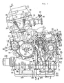
Fig. 2 is a left lateral view of a power unit. -
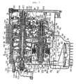
Fig. 3 is a right lateral view of the power unit. -
Fig. 4 is a cross-sectional view taken along line 4-4 ofFig. 2 . -
Fig. 5 is a cross-sectional view taken along line 5-5 ofFig. 4 . -
Fig. 6 is a cross-sectional view illustrating a crankcase and a cover member joined to the crankcase, taking along the same cross-section as that ofFig. 4 . -
Fig. 7 is an enlarged cross-sectional view taken along line 7-7 ofFig. 2 . -
Fig. 8 is an enlarged view of a portion indicated witharrow 8 ofFig. 7 . -
Fig. 9 is an enlarged view of a portion indicated with arrow 9 ofFig. 7 . -
Fig. 10 is an enlarged view of a portion indicated witharrow 10 ofFig. 7 . -
Fig. 11 illustrates the crankcase and a left cover member as viewed from the direction of arrow line 11-11 ofFig. 2 . -
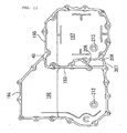
Fig. 12 illustrates an oil pan as viewed from the direction of arrow 12-12 ofFig. 2 . -
Fig. 13 is a rear view of the power unit as viewed from the rear. -
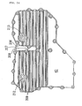
Fig. 14 illustrates the oil pan as viewed from the direction of arrow 14 ofFig. 2 . -
Fig. 15 is a partially cut-away view illustrating the power unit as viewed from the direction of arrow 15-15 ofFig. 2 . - An embodiment of the present invention will hereinafter be described with reference to the accompanying drawings.
- It is to be noted that the front and rear or back and the left and right in the embodiment refer to respective directions in the state where the motorcycle faces the front of the traveling direction thereof.
- Referring first to
Fig. 1 , a body frame F of the motorcycle includes ahead pipe 16; amain frame 17; a pair of left and right downframes 18;pivot plates 19; a pair of left andright seat rails 20; and a pair of left andright connection frames 21. Thehead pipe 16 steerably supports afront fork 15 which has a lower end rotatably supporting a front wheel WF. Themain frame 17 extends rearward from thehead pipe 16, bends therefrom and extends downward to form a hangingportion 17a at the rear portion thereof. Thedown frame 18 has aslant portion 18a which slants rearward downwardly from thehead pipe 16 and ahorizontal portion 18b which extends rearward from the rear portion of theslant portion 18a. In addition, thedown frames 18 are located below themain frame 17. Thepivot plate 19 connects a rear end of each horizontal portion of thedown frames 18 with a lower end of each hangingportion 17a of themain frames 17. Theseat rail 20 extends rearward from the upper portion of the hangingportion 17a of themain frame 17. Theconnection frame 21 connects thepivot plate 19 with the intermediate portion of theseat rail 20. - A
steering handlebar 22 is connected to the upper end of thefront fork 15. An occupant'sseat 23 is mounted on theseat rails 20. Afuel tank 24 is located in front of the occupant'sseat 23 so as to be mounted on and straddle themain frame 17. - The most part of a power unit P is disposed in a portion surrounded by the
main frame 17 and by thedown frames 18. The power unit P includes an in-series 4-cylinder internal combustion engine E supported by thedown frames 18 and by thepivot plates 19 and a power transmission device T which changes and reduces the speed of the power of the engine E and transmits it to a rear wheel WR. - The
pivot plate 19 swingably supports the front end portion of aswing arm 25 via asupport shaft 26 and theswing arm 25 has a rear end portion which rotatably supports a rear wheel WR. Arear cushion 27 is provided between each of theseat rails 20 and a corresponding one of theswing arms 25. - Chain transmission means 33 is provided between an
output shaft 28 of the power unit P and anaxle 29 of the rear wheel WR. The chain transmission means 33 includes adrive sprocket 30 provided on theoutput shaft 28, a drivensprocket 31 secured to theaxle 29, and anendless chain 32 wound around the drive sprocket 30 and around the drivensprocket 31. - Referring to
Figs. 2 and3 , the internal combustion engine E includes acrankcase 36; acylinder block 37 joined to the upper portion of thecrankcase 36; acylinder head 38 joined to the upper end of thecylinder block 37; ahead cover 38 joined to thecylinder head 38; and anoil pan 40 joined to the lower portion of thecrankcase 36. -
Intake pipes 41 are each joined to the rear lateral surface of thecylinder head 38 so as to be associated with a corresponding one of cylinders. Theintake pipe 41 is joint at an upstream end to athrottle body 43 attached with afuel injection valve 42. Thethrottle body 43 is joined at an upstream end to an air cleaner 44 (seeFig. 1 ) located on the left side of the body frame F and above the rear portion of the power unitP. Exhaust pipes 45 are each joined to the front lateral surface of thecylinder head 38 so as to be associated with a corresponding one of the cylinders. As shown inFig. 1 , theexhaust pipe 45 passes below the right side of the power unit P, extending rearward, and is joined to anexhaust muffler 46 disposed on the right side of the rear wheel WR. - The
crankcase 36 includes an uppercase half body 48 and a lowercase half body 49 which are coupled to each other at asplit face 47 slanting forwardly upwardly. Acrankshaft 50 having an axis CL1 extending in the width-direction of the motorcycle is rotatably carried between the upper casehalf body 48 and the lowercase half body 49. - With additional reference to
Fig. 4 , thecylinder block 37 is joined to the upper casehalf body 48 of thecrankcase 36 so as to slant forwardly upwardly toward the front of the traveling direction of the motorcycle. Thecylinder block 37 is provided with four cylinder bores 51 lined in the direction of the axial line CL1 of thecrankshaft 50. Apiston 52 slidably fitted into each of the cylinder bores 51 is connected via a connectingrod 53 to a crankpin 50a provided for thecrankshaft 50. - The
crankcase 36 is provided with six, first through sixth,journal walls 54 to 59 spaced apart from each other in the direction of the axial line CL1 of thecrankshaft 50 from the left side to the right side in the state of being mounted on the motorcycle. Thecrankshaft 50 is rotatably journaled by the first throughsixth journal walls 54 to 59. - A
rotor 60 is secured to an end of thecrankshaft 50 outwardly projecting from the left lateral wall, i.e., thefirst journal wall 54 of thecrankcase 36. Astator 61 constituting agenerator 62 along with therotor 60 is attached to agenerator cover 63 fastened to the left lateral wall of thecrankcase 36 so as to cover thegenerator 62. - With additional reference to
Fig. 5 , astarter motor 64 disposed within thegenerator cover 63 is mounted above the split face 47 to thecrankcase 36 so as to have a rotational axis parallel to thecrankshaft 50. A one-way clutch 67 is interposed between agear 66 receiving power transmitted from thestarter motor 64 via areduction gear mechanism 65 and therotor 60 of thegenerator 62 so as to enable power transmission from the side of thegear 66. - As clearly shown in
Fig. 4 , a pulser 68 is secured to an end of thecrankshaft 50 projecting from the right lateral wall, i.e., thesixth journal wall 59 of thecrankcase 36. Arotation number sensor 70 is attached inside apulser cover 69 so as to face the outer circumference of the pulser 68. Thepulser cover 69 is joined to thecrankcase 36 to cover the pulser 68. - The third and
fourth journal walls chain chamber 73 is formed in thecylinder block 37 and in thecylinder head 38 at a portion corresponding to between the third andfourth journal walls - The
cylinder head 38 is provided with a pair ofintake valves 74 for each cylinder and with a pair ofexhaust valves 75 for each cylinder. Theintake valves 74 and theexhaust valves 75 are provided in an openable and closable manner while being biased by springs in the valve-closing direction. Avalve operating chamber 76 is formed between thecylinder head 38 and thehead cover 39. Avalve operating system 79 is received in thevalve operating chamber 76 to drivingly open and close theintake valves 74 and theexhaust valves 75. Thevalve operating system 79 includes an intakeside cam shaft 77 disposed parallel to thecrankshaft 50 to be associated with theintake valves 74; and an exhaustside cam shaft 78 disposed parallel to thecrankshaft 50 to be associated with theexhaust valves 75. - Rotational power is transmitted from the
crankshaft 50 to theintake side camshaft 77 and to theexhaust side camshaft 78 at a reduction ratio of 1/2 by timing transmission means 80. The timing transmission means 80 includes adrive sprocket 81, drivensprockets endless timing chain 84. Thedrive sprocket 81 is provided on thecrankshaft 50 between the third andfourth journal walls sprockets side cam shaft 77 and on the exhaustside cam shaft 78, respectively, at respective positions corresponding to thedrive sprocket 81. Thetiming chain 84 is wound around thedrive sprocket 81 and around the drivensprockets chain chamber 73. - With additional reference to
Fig. 6 , thecrankcase 36 includes afront half portion 36a and arear half portion 36b. Thefront half portion 36a is provided with the first throughsixth journal walls 54 to 59. Therear half portion 36b has a right end portion flush with a right end portion of thefront half portion 36a and a left end portion located inward of a left end portion of thefront half portion 36a. In addition, therear half portion 36b has a width narrower than that of thefront half portion 36a in the direction of the axial line CL1 of thecrankshaft 50. Aleft cover member 85 is joined to therear half portion 36b from the left side and a firstright cover member 86 is joined to therear half portion 36b from the right side. A secondright cover member 87 is joined to the firstright cover member 86 from the right side. A thirdright cover member 88 is joined to thefront half portion 36a andrear half portion 36b of thecrankcase 36 so as to cover the secondright cover member 87 from the right outside. - The
crankcase 36 is internally formed with acrank chamber 89 which receives therein the most portion of thecrankshaft 50 and communicates with the cylinder bores 51. Thecrankcase 36 and theleft cover member 85, the firstright cover member 86 and the secondright cover member 87 each of which is joined to thecrankcase 36 define a continuouslyvariable transmission chamber 90. Thecrankcase 36 is formed with apartition wall portion 36c which is disposed at a connection portion between thefront half portion 36a and therear half portion 36b to separate between thecrank chamber 89 and the continuouslyvariable transmission chamber 90. - Referring to
Fig. 7 , the power transmission device T including the continuouslyvariable transmission 91 is housed in the continuouslyvariable transmission chamber 90. The power transmission device T includes the belt type continuouslyvariable transmission 91 which enables continuously variable speed by hydraulic control; and an input clutch 92 interposed between thecrankshaft 50 and the continuouslyvariable transmission 91. The power transmission device T further includes theoutput shaft 28 which outwardly projects from theleft cover member 85 to transmit power to the rear wheel WR; and astart clutch 93 and agear transmission mechanism 94 interposed between the continuouslyvariable transmission 91 and the output shat 28. - The continuously
variable transmission 91 includes adrive pulley shaft 95 parallel to thecrankshaft 50; a drivenpulley shaft 96 disposed above thedrive pulley shaft 95; adrive pulley 97 provided on thedrive pulley shaft 95; a drivenpulley 98 provided on the drivenpulley shaft 96; and anendless metal belt 99 wound around thedrive pulley 97 and around the drivenpulley 98. In addition, the continuouslyvariable transmission 91 is disposed rearward of the axial line CL1 of thecrankshaft 50. - Additionally, the axial line CL1 of the
crankshaft 50, the axial line CL2 of thedrive pulley 97, i.e., the axis of thedrive pulley shaft 95 and the axial line CL3 of the drivenpulley 98, i.e., the axis of the drivenpulley shaft 96 are each located at a corresponding one of the apexes of an imaginary triangle VT1 on a view projected on a plane perpendicular to the axial line CL1 of thecrankshaft 50 as clearly shown inFig. 5 . The axial line CL1 of thecrankshaft 50 and the axial line CL3 of the drivenpulley 98 are located on the split face 47 of thecrankcase 36. Incidentally, the drivenpulley 98 is a downside-located pulley of thedrive pulley 97 and drivenpulley 98 located one above the other. - The
partition wall 36c provided in thecrankcase 36 to separate between thecrank chamber 89 and the continuouslyvariable transmission chamber 90 is formed to slant toward thecrankshaft 50 at a portion above thesplit face 47. The upside-locateddrive pulley 97 of thedrive pulley 97 and drivenpulley 98 is located at a position offset toward thecrankshaft 50 with respect to a first vertical line VL1 passing the axial line CL3 of the downside-located drivenpulley 98. - The drive
pulley shaft 95 rotatably passes through therear half portion 36b of thecrankcase 36, the firstright cover member 86 and the secondright cover member 87. The drivenpulley shaft 96 rotatably passes through therear half portion 36b of thecrankcase 36 and the firstright cover member 86. - The external wall of the continuously
variable transmission chamber 90 is composed of therear half portion 36b of thecrankcase 36, theleft cover member 85, the firstright cover member 86 and the secondright cover member 87. Afirst oil pump 100 is disposed at theleft cover member 85 which is a wall portion on one end side of thedrive pulley shaft 95 so as to be coupled to one end of thedrive pulley shaft 95. - The
first oil pump 100 is a trochoid pump. Apump case 101 for thefirst oil pump 100 includes theleft cover member 85; a flat plate-like first case member 102 abutted against the inner surface of theleft cover member 85; and a bowl-likesecond case member 103. Afirst pump chamber 104 is defined between the first case member 102 and thesecond case member 103. The first case member 102 is gripped between theleft cover member 85 and thesecond case member 103. The first andsecond case members 102, 103 are co-fastened to theleft cover member 85 with a plurality ofbolts 105. - One end portion of the
drive pulley shaft 95 rotatably passes through thesecond case member 103 of thepump case 101 and projects into thefirst pump chamber 104. One end of thedrive pulley shaft 95 is coupled to an inner rotor 106, of the inner rotor 106 and an outer rotor 107, incapably of relative rotation. The inner rotor 106 and the outer rotor 107 mesh with each other and are housed in thefirst pump chamber 104. Aroller bearing 108 is interposed between thesecond case member 103 and thedrive pulley shaft 95. - A
water pump 109 coaxial with thefirst oil pump 100 is disposed on the external surface side of theleft cover member 85 at a portion corresponding to thefirst oil pump 100. Apump case 110 of thewater pump 109 includes athird case member 111 and afourth case member 112. Thethird case member 85 has a tubular supportcylindrical portion 111 a which is formed integrally therewith, extends coaxially with thedrive pulley shaft 95 and is partially fitted into theleft cover member 85 in a liquid-tight manner. Thefourth case member 112 is joined to thethird case member 111 to define asecond pump member 113 therebetween. The third andfourth case members left cover member 85 with a plurality ofbolts 114. - An
impeller 115 housed in thesecond pump chamber 113 is secured to one end of apump shaft 116. Thepump shaft 116 is liquid-tightly and rotatably inserted into a supportcylindrical portion 111 a. One end of thepulley shaft 95 is coaxially coupled to the other end of thepump shaft 116 incapably of relative rotation. - On the other hand, the other end of the
drive pulley shaft 95 is fitted into the thirdright cover member 88 via anannular sealing member 117. Aball bearing 118 is interposed between thedrive pulley shaft 95 and the secondright cover member 87. - One end of driven
pulley shaft 96 is rotatably journaled by theleft cover member 85 via aroller bearing 119. The other end of the drivenpulley shaft 96 rotatably passes through the firstright cover member 86. Aball bearing 120 is interposed between the drivenpulley shaft 96 and the firstright cover member 86. - Rotational power from the
crankshaft 50 is transmitted to the drivepulley shaft 95 via a primaryreduction gear mechanism 121 and via adamper spring 122. The primaryreduction gear mechanism 121 reduces the speed of the rotational power from thecrankshaft 50 and transmits it toward thedrive pulley shaft 95. The primaryreduction gear mechanism 121 includes aprimary drive gear 123 provided on thecrankshaft 50 and a primary drivengear 124 meshing with theprimary drive gear 123. As clearly shown inFig. 4 , theprimary drive gear 123 is integrally formed on thecrankshaft 50 so as to be located between the fifth andsixth journal walls member 125 having acylindrical portion 125a coaxially surrounding thedrive pulley shaft 95 is secured to the drivepulley shaft 95 between the second and thirdright cover members gear 124 is carried on the transmittingmember 125 so as to enable relative rotation within a limited range. Thedamper spring 122 is provided between the primary drivengear 124 and the transmittingmember 125. Anannular sealing member 126 is interposed between thecylindrical portion 125a of the transmittingmember 125 and the secondright cover member 87. - Referring to
Fig. 8 , theinput clutch 92 is attached to the drivepulley shaft 95 between the first and secondright cover members variable transmission chamber 90. Theinput clutch 92 includes a clutch outer 131; a clutch inner 132; a plurality of firstdrive friction plates 133; a plurality of first drivenfriction plates 134; a pressure-receiving plate 135; a pressurizingplate 136; and aclutch spring 137. The clutch outer 131 has a tubular innercylindrical portion 131 a joined to the drivepulley shaft 95 incapably of relative rotation and an outercylindrical portion 131 b coaxially surrounding the innercylindrical portion 131a. The clutch inner 132 has acylindrical portion 132a coaxially disposed between the innercylindrical portion 131 a and outercylindrical portion 131 b of the clutch outer 131. The firstdrive friction plates 133 are axially slidably spline-fitted to the outercylindrical portion 131 b of the clutch outer 131. The first drivenfriction plates 134 are alternately superimposed on the firstdrive friction plates 133 and axially slidably spline-fitted to thecylindrical portion 132a of theclutch inner 132. The pressure-receiving plate 135 is secured to the outercylindrical portion 131 b of the clutch outer 131 so as to face, from one axial direction, the firstdrive friction plates 133 and first drivenfriction plates 134 that are superimposed on each other. The pressurizingplate 136 faces, from the other axial direction, the firstdrive friction plates 133 and first drivenfriction plates 134 that are superimposed on each other. Theclutch spring 137 biases the pressurizingplate 136 toward the side where the pressurizingplate 136 is spaced from the pressure-receiving plate 135. - The pressurizing
plate 136 is adapted to define a firsthydraulic chamber 138 between the clutch outer 131 and the pressurizingplate 136. The pressurizingplate 136 is slidably supported by the innercylindrical portion 131 a and outercylindrical portion 131 b of the clutch outer 131. Theclutch spring 137 is compressively provided between the pressurizingplate 136 and a spring-receivingmember 139 attached to the innercylindrical portion 131 a of the clutch outer 131. The drivepulley shaft 95 is provided with afirst oil hole 140 communicating with the firsthydraulic chamber 138. - With such an
input clutch 92, the hydraulic pressure of the firsthydraulic chamber 138 is increased to move the pressurizingplate 136 forward, i.e., toward the pressure-receiving plate 135 against the spring force of theclutch spring 137. The firstdrive friction plates 133 and first drivenfriction plates 134 are pressurized and gripped between the pressurizingplate 136 and the pressure-receiving plate 135. Thus, a clutch-on state is brought where power is transmitted from thedrive pulley shaft 95 to theclutch inner 132. A clutch-off state is brought according to the reduced hydraulic pressure of the firsthydraulic chamber 138. - Referring to
Fig. 9 , thedrive pulley 97 includes a drive side stationarypulley half body 141 and a drive side movablepulley half body 142. The stationarypulley half body 141 has a tubular cylinder-shaft portion 141 a integrally formed therewith to coaxially surround thedrive pulley shaft 95 and is carried on thedrive pulley shaft 95 for relative rotation. The movablepulley half body 142 is carried on the cylinder-shaft portion 141 a incapably of relative rotation but capably of axial slide and is opposed to the drive side stationarypulley half body 141. The drivenpulley 98 includes a driven side stationarypulley half body 143 integrally provided on the drivenpulley shaft 96; and a driven side movablehalf body 144 which is carried on a drivenpulley shaft 96 incapably of relative rotation but capably of axial slide and is opposed to the driven side stationarypulley half body 143. - The
belt 99 is wound around thedrive pulley 97 and around the drivenpulley 98. The axial relative positions of the drive side movablepulley half body 142 to the drive side stationarypulley half body 141 and of the driven side movablepulley half body 144 to the movable side stationarypulley half body 143 are hydraulically controlled to change the winding radius of thebelt 99 around thedrive pulley 97 and around the drivenpulley 98. Thus, the power transmission from thedrive pulley shaft 95 to the drivenpulley shaft 96 is changed in speed in a stepless manner. - The cylinder-
shaft portion 141 a integrally provided for the drive side stationarypulley half body 141 coaxially surrounds thedrive pulley shaft 95 in such a manner that a pair ofneedle bearings portion 141 a and thedrive pulley shaft 95. One end of the cylinder-shaft portion 141 a rotatably passes through the left lateral wall of therear half portion 36b of thecrankcase 36. Aball bearing 146 is interposed between the cylinder-shaft portion 141 a and thecrankcase 36. The cylinder-shaft portion 141 a rotatably passes through the firstright cover member 86 and is coupled to theclutch inner 132 of theinput shaft 92 coaxially and incapably of relative rotation. The cylinder-shaft portion 141 a, i.e., the drive side stationarypulley half body 141 is rotated together with thedrive pulley shaft 95 in the clutch-on state of theinput clutch 92. Aball bearing 147 is interposed between the cylinder-shaft portion 141 a and the firstright cover member 86. - The drive side movable
pulley half body 142 is disposed at a position opposed to the drive side stationarypulley half body 141 from the side opposite to the firstright cover member 86. In addition, the drive side movablepulley half body 142 has a cylindricalfirst boss portion 142a that is formed integrally therewith to coaxially surround the cylinder-shaft portion 141 a and to be coupled to the cylinder-shaft portion 141 a incapably of relative rotation but capably of axial slide. A drive sidehydraulic drive mechanism 148 for slidably driving the drive side movablepulley half body 142 is disposed on the cylinder-shaft portion 141 a on the side opposed to the drive side stationarypulley half body 141 with respect to the drive side movablepulley half body 142. - The drive side
hydraulic drive mechanism 148 includes acylindrical case portion 142b; a ring plate-likefirst end plate 150; a stationary bawl-like body 151; and asecond end plate 152. Thecase portion 142b is integrally formed on the outer circumferential portion of the drive side movablepulley half body 142 so as to coaxially surround thefirst boss portion 142a and to extend oppositely to the drive side stationarypulley half body 141. Thefirst end plate 150 is in slidable contact with the inner circumference of thecase portion 142b and with the outer circumference of thefirst boss portion 142a in a liquid-tight manner to define a secondhydraulic pressure chamber 149 between the drive side movablepulley half body 142 and thefirst end plate 150. The stationary bowl-like body 151 is secured to the cylinder-shaft portion 141 a on the side opposite to the drive side stationarypulley half body 141 with respect to the drive side movablepulley half body 142 and is abutted against thefirst end plate 150 at its leading end portion. Thesecond end plate 152 is in slidable contact with the inner circumference of the stationary bowl-like body 151 in a liquid-tight manner and is secured at an inner circumferential portion to thefirst boss portion 142a to define a thirdhydraulic chamber 153 between the stationary bowl-like body 151 and thesecond end plate 152. - The cylinder-
shaft portion 141 a is provided with asecond oil hole 154 communicating with the second and thirdhydraulic chambers annular chamber 155 is defined between thedrive pulley shaft 95 and the cylinder-shaft portion 141a to communicate with thesecond oil hole 154. A pair ofannular sealing members drive pulley shaft 95 outwardly of both theneedle bearings annular chamber 155. Further, thedrive pulley shaft 95 is provided with a plurality of third oil holes 157 communicating with theannular chamber 155. - In this way, the drive side movable
pulley half body 142 is biased by the hydraulic force according to the hydraulic pressure applied to the second and thirdhydraulic chambers pulley half body 142 close to the drive side stationarypulley half body 141 to increase the winding radius of thebelt 99 wound around thedrive pulley 97. - The driven side stationary
pulley half body 143 is integrally provided on the drivenpulley shaft 96 at a position corresponding to the drive side movablepulley half body 142 of thedrive pulley 97. The drive side movablepulley half body 142 and the driven side stationarypulley half body 143 are disposed to partially overlap each other as viewed from the respective directions of the respective axial lines CL2, CL3 of thedrive pulley shaft 95 and the drivenpulley shaft 96. In order to avoid the mutual interference between the drive side movablepulley half body 142 and the driven side stationarypulley half body 143, arelief recess portion 158 is provided on the outer circumference of the drive side movablepulley half body 142. - Focusing on
Fig. 7 , the driven side movablepulley half body 144 is disposed at a position corresponding to the drive side stationarypulley half body 141 of thedrive pulley 97. In addition, the driven side movablepulley half body 144 is integrally provided in an internal circumferential portion with asecond boss portion 144a. Thesecond boss portion 144a extends toward the side opposite to the driven side stationarypulley half body 143 and coaxially surrounds the drivenpulley shaft 96. Thesecond boss portion 144a is coupled to the drivenpulley shaft 96 incapably of relative rotation but capably of axial movement. - Additionally, the drive side stationary
pulley half body 141 and the driven side movablepulley half body 144 are disposed to partially overlap each other as viewed from the respective directions of the respective axial lines CL2, CL3 of thedrive pulley shaft 95 and the drivenpulley shaft 96. In order to avoid the occurrence of the mutual interference between the drive side stationarypulley half body 141 and the driven side movablypulley half body 144, arelief recess portion 159 is provided on the outer circumference of the driven side movablepulley half body 144. - As described above, the
relief recess portion 158 is provided on the outer circumference of the drive side movablepulley half body 142 to avoid the occurrence of the mutual interference between the drive side movablepulley half body 142 and the driven side stationarypulley half body 143. In addition, therelief recess portion 159 is provided on the outer circumference of the driven side movablepulley half body 144 to avoid the occurrence of the mutual interference between the drive side stationarypulley half body 141 and the driven side movablypulley half body 144. Thus, thedrive pulley shaft 95 and the drivenpulley shaft 96 are made close to each other to bring the continuouslyvariable transmission 91 into a compact configuration. - A driven side
hydraulic drive mechanism 160 for slidably driving the driven side movablepulley half body 144 is disposed on the drivenpulley shaft 96 on the side opposite to the driven side stationarypulley half body 143 with respect to driven side movablepulley half body 144. The driven sidehydraulic drive mechanism 160 includes atubular case member 161; anend wall member 163; and a coil spring 164. Thecase member 161 coaxially surrounds thesecond boss portion 144a, is secured at one end to the outer circumferential portion of the driven side movablepulley half body 144 and extends toward the side opposite to the driven side stationarypulley half body 143. Theend wall member 163 is in slidable contact with the inner circumference of thecase member 161 in a liquid-tight manner to define a fourthhydraulic chamber 162 between the driven side movablepulley half body 144 and theend wall member 163. Theend wall member 163 is secured at an inner circumference to the drivenpulley shaft 96. The coil spring 164 is compressively provided between the driven side movablehalf body 144 and theend wall member 163 to prevent the slack of thebelt 99 encountered when the internal combustion engine E is stopped. - The driven
pulley shaft 96 is provided with afourth oil hole 165 communicating with the fourthhydraulic chamber 162. In this way, the driven side movablepulley half body 144 is biased by the hydraulic force according to the hydraulic pressure applied to the fourthhydraulic chamber 162 to move the driven side movablepulley half body 144 close to the driven side stationarypulley half body 143 to increase the winding radius of thebelt 99 wound around the drivenpulley 98. Additionally, arestrictive plate portion 161 a is integrally provided at the other end of thecase member 161 to protrude radially inwardly. Therestrictive plate portion 161 a is abutted against theend wall member 163 from the side opposite to the driven side stationarypulley half body 143 to restrict the movement of the driven side movablepulley half body 144 close to the driven side stationarypulley half body 143. - Referring to
Fig. 10 , thestart clutch 93 is mounted to the drivenpulley shaft 96 between the drivenpulley 98 of the continuouslyvariable transmission 91 and theleft cover member 85. Thestart clutch 93 includes a clutch outer 169; a clutch inner 170; a plurality of seconddrive friction plates 172; a plurality of second drivenfriction plates 173; a pressure-receivingplate 174; apiston 175; and aspring 177. Atubular boss member 168 is joined to the inner circumference of the clutch outer 169 and to the drivenpulley shaft 96 incapably of relative rotation. The clutch inner 170 is coaxially surrounded by the clutch outer 169 and carried on the drivenpulley shaft 96 via aneedle bearing 171 for relative rotation. The seconddrive friction plates 172 are engaged with the clutch outer 169 incapably of relative rotation. The second drivenfriction plates 173 are engaged with the clutch inner 170 incapably of relative rotation and alternately superposed on the seconddrive friction plates 172. The pressure-receivingplate 174 is fixedly supported by the clutch outer 169 so as to face the second drive and drivenfriction plates piston 175 grips the second drive and drivenfriction plates plate 174 and thepiston 175 and defines a fifth hydraulic chamber 176 between the clutch outer 169 and thepiston 175. Thespring 177 biases thepiston 175 in a direction to reduce the volume of the fifth hydraulic chamber 176. - The inner circumferential portion of the
piston 175 is in slidable contact with the outer circumferential portion of theboss member 168 in a liquid-tight manner. The outer circumferential portion of thepiston 175 is in slidable contact with the clutch outer 169 in a liquid-tight manner. In addition, the drivenpulley shaft 96 is provided with afifth oil hole 178 communicating with the fifth hydraulic chamber 176. According to an increase in the hydraulic pressure of the fifth hydraulic chamber 176, thepiston 175 is operated to grip and pressurize the second drive and drivenfriction plates plate 174 and thepiston 175. Thus, thestart clutch 93 is brought into a clutch-on state where the rotational power transmitted from the drivenpulley shaft 96 to the clutch outer 169 is transmitted to theclutch inner 170. - A
wall member 180 is secured at an inner circumferential portion to theboss member 168 to define acanceller chamber 179 between thepiston 175 and thewall member 180 and on the side opposite to the fifth hydraulic chamber 176. Thepiston 175 is in slidable contact with the outer circumferential portion of thewall member 180 in a liquid-tight manner. Additionally, thespring 177 is housed in thecanceller chamber 179 and interposed between thepiston 175 and thewall member 180. The drivenpulley shaft 96 and theboss member 169 are provided with abranch oil passage 181 adapted to lead lubricating oil to thecanceller chamber 179. Even if a centrifugal force resulting from rotation is applied to the oil in the fifth hydraulic chamber 176 under reduced pressure to generate a force pressuring thepiston 175, the same centrifugal force is applied to the oil in thecanceller chamber 179. Thus, it can be avoided that thepiston 175 may undesirably be moved to grip the second drive and drivenfriction plates plate 174 and thepiston 175. - Focusing on
Fig. 4 , one end of theoutput shaft 28 rotatably passes through theleft cover member 85. Anannular sealing member 182 and aball bearing 183 are interposed between theoutput shaft 28 and theleft cover member 85 in the order from the external side. Thedrive sprocket 30 constituting part of the chain transmission means 33 is secured to one end of theoutput shaft 28 extending from theleft cover member 85. The other end of theoutput shaft 28 is rotatably journaled by therear half portion 36b of thecrankcase 36 via aroller bearing 184. - The
gear transmission mechanism 94 is disposed between thecrankcase 36 and theleft cover member 85 and installed between theclutch inner 170 of thestart clutch 93 and theoutput shaft 28. Thegear transmission mechanism 94 includes adrive gear 185 formed integrally with the clutch inner 170; and a drivengear 186 provided integrally with theoutput shaft 28 so as to mesh with thedrive gear 185. In the clutch-on state of the start clutch 93, the rotational power of the drivenpulley shaft 96 is transmitted to theoutput shaft 28 via thegear transmission mechanism 94. - Incidentally, the
drive pulley shaft 95 passes through the secondright cover 87 interposed between thecrank chamber 89 and the continuouslyvariable transmission chamber 90, of therear half portion 36b of thecrankcase 36, theleft cover member 85, the firstright cover member 86 and the secondright cover member 87 constituting the outer wall of the continuouslyvariable transmission chamber 90. Theannular sealing member 126 is interposed between the secondright cover member 87 and the transmittingmember 125 fixedly brought into close contact with the outer circumference of thedrive pulley shaft 95. Also theannular sealing member 117 is interposed between the other end of the tubulardrive pulley shaft 95 and the thirdright cover member 88. In this way, the continuouslyvariable transmission chamber 90 is liquid-tightly isolated from thecrank chamber 89. - In
Fig. 11 , an endlessly continuousfirst split face 190 is formed on the lower surface of thefront half portion 36a in the lowercase half body 49 of thecrankcase 36 so as to correspond to the crankchamber 39. In addition, asecond split face 191 is formed on the lower surface of therear half portion 36b in the lowercase half body 49 of thecrankcase 36 and on the lower surface of theleft cover member 85 joined to the rearhalf body 36b so as to correspond to the continuouslyvariable transmission chamber 90 while endlessly continuing into and sharing part of thefirst split face 190 at thepartition wall portion 36c. - With additional reference to
Fig. 12 , theoil pan 40 is provided with apartition wall 193 adapted to separate an internal combustion engine sideoil storage chamber 196 from a continuously variable transmission sideoil storage chamber 197. The internal combustion engine sideoil storage chamber 196 is adapted to store oil for various lubricating portions of the internal combustion engine E. The continuously variable transmission sideoil storage chamber 197 is adapted to store oil for lubricating the power transmission device T including the continuouslyvariable transmission 91, for shift-controlling the continuouslyvariable transmission 91 and for controlling theinput clutch 92 and thestart clutch 93. In addition, theoil pan 40 is formed on an upper surface with an endlessthird split face 194 and afourth split surface 195. Thethird split face 194 is joined to thefirst split face 190 of thecrankcase 36. Thefourth split face 195 is joined to thesecond split face 191 between thecrankcase 36 and theleft cover member 85 while endlessly continuing into and sharing part of thethird split face 194 at a portion corresponding to thepartition wall 193. - In this way, the
oil pan 40 is fastened to thecrankcase 36 and to theleft cover member 85 with a plurality ofbolts 198 in such a manner that the third and fourth split faces 194, 195 are joined to the first and second split faces 190, 191. The internal combustion engine sideoil storage chamber 196 is allowed to communicate with the lower portion of thecrank chamber 89. - Focusing on
Fig. 7 , aceiling wall portion 199 is provided on therear half portion 36b of the lowercase half body 49 in thecrankcase 36 and on theleft cover member 85 so as to be interposed between the continuously variable transmission sideoil storage chamber 197 and the continuouslyvariable transmission chamber 90 and to serve as a ceiling wall of the continuously variable transmission sideoil storage chamber 197. Theceiling wall portion 199 is provided with a plurality ofcommunication holes 200 adaptable for communication between the continuously variable transmission sideoil storage chamber 197 and the continuouslyvariable transmission chamber 90. This allows the continuously variable transmission sideoil storage chamber 197 to communicate with the continuouslyvariable transmission chamber 90. - Incidentally, the continuously variable transmission side
oil storage chamber 197 is defined by the lower portion of theleft cover member 85, theoil pan 40 and theceiling wall portion 199. The continuously variably transmission sideoil storage chamber 197 partially protrudes from the continuouslyvariable transmission chamber 90 outwardly in the width-direction of the motorcycle. The lower portion of theleft cover member 85 and the left lateral wall of theoil pan 40 are formed to protrude outwardly from the upper portion of theleft cover member 85 as clearly shown inFig. 7 . - Additionally, the continuously variable transmission side
oil storage chamber 197 is disposed to be offset leftward from the body centerline C1 in such a manner that its center C2 with respect to the width-direction of the motorcycle is offset leftward or rightward from the body centerline C1 on the center of the width-direction. In this embodiment, the center C2 is disposed to be offset leftward from the body centerline C1. The continuously variable transmission sideoil storage chamber 197 is formed to partially protrude outwardly from the continuouslyvariable transmission chamber 90 on the side where the continuously variable transmission sideoil storage chamber 197 is offset from the body centerline C1. The continuouslyvariable transmission 91 is disposed to be offset rightward from the body centerline C1 conversely to the continuously variable transmission sideoil storage chamber 197. - As described above, the center C2 of the continuously variable transmission side
oil storage chamber 197 with respect to the width-direction of the motorcycle is disposed to be offset leftward from the body centerline C1. In addition, on the offset side, the continuously variable transmission sideoil storage chamber 197 protrudes outwardly from the continuouslyvariable transmission chamber 90. Thus, as shown inFig. 13 , an empty space can be ensured on the right side from the body centerline C1 and below thecrankcase 36. The fourexhaust pipes 45, a collectingexhaust pipe 210 collecting theexhaust pipes 45 and the like are arranged in the space. - The body frame F or internal combustion engine E is provided with
respective steps steps oil storage chamber 197 is formed to partially protrude outwardly (in this embodiment, leftwardly) from the continuouslyvariable transmission chamber 90 in a range where theoil storage chamber 197 is accommodated in the bank angle α. - The
first oil pump 100 is disposed on the upper portion of theleft cover member 85 serving as a wall portion constituting part of an external wall of the continuouslyvariable transmission chamber 91 so as to be coupled to one end of thedrive pulley shaft 95 constituting part of the continuouslyvariable transmission 91. Thefirst oil pump 100 is adapted to pump oil stored in the continuously variable transmission sideoil storage chamber 197, the oil being used for lubricating the power transmission device T including the continuouslyvariable transmission 91, for shift-controlling the continuouslyvariable transmission 91 and for controlling theinput clutch 92 and thestart clutch 93. The continuously variable transmission sideoil storage chamber 197 is formed to partially protrude outwardly from the wall portion on which thefirst oil pump 100 is mounted, i.e., from the upper portion of theleft cover member 85. - An
oil strainer 201 is disposed in the continuously variable transmission sideoil storage chamber 197. Aconnection pipe 202 connected to theoil strainer 201 is provided to extend downward at a portion, on the side of theleft cover member 85, of theceiling wall portion 199 which is provided on therear half portion 36b of the lowercase half body 49 and on theleft cover member 85 so as to serve as a ceiling wall of the continuously variable transmission sideoil storage chamber 197, i.e., in a protruding portion of the continuously variable transmission sideoil storage chamber 197. - A
suction oil passage 203 is provided on the outside surface of theleft cover member 85 to introduce the oil of the continuously variable transmission sideoil storage chamber 197 into thefirst oil pump 100. Specifically, thesuction oil passage 203 is provided to extend vertically so as to have a lower end portion allowed to communicate with theconnection pipe portion 202 disposed at a portion, of the ceiling wall of the continuously variable transmission sideoil storage chamber 197, protruding outwardly of the continuouslyvariable transmission chamber 90, and an upper portion allowed to communicate with thefirst oil pump 100. - A gauge hole 204 (see
Fig. 11 ) is provided at a portion, outwardly protruding from the continuouslyvariable transmission chamber 90, of theceiling wall portion 199 which is a ceiling wall of the continuously variable transmission sideoil storage chamber 197. Thegauge hole 204 has an axis that slant to be spaced from the outer surface of theleft cover member 85 as it goes upward. A level gauge 205 (seeFigs. 2 and7 ) is removably attached to thegauge hole 204 in order to check the amount of the oil stored in the continuously variable transmission sideoil storage chamber 197. - With additional reference to
Fig. 14 , theoil pan 40 is provided with agroove 206 corresponding to a gap between thecrankcase 36 and theleft cover member 85 at a portion provided with thepartition wall 193. Thegroove 206 is provided so as to open to below and to one side (in this embodiment, the left side, i.e., the side opposite to the right side where theexhaust pipes 45 and the collectingexhaust pipe 210 are disposed). Reinforcingbridge portions groove 206. A plurality ofribs 209 are provided to project from the bottom portion of theoil pan 40 and line up in the back and forth direction of the motorcycle. Theoil pan 40 is provided in the bottom portion with adrain hole 212 communicating with the inner lower portion of the internal combustion engine sideoil storage chamber 196 and with adrain hole 213 communicating with the inner lower portion of the continuously variable transmission sideoil storage chamber 197. - Focusing on
Fig. 7 , oil discharged from thefirst oil pump 100 is led via a discharge oil passage 214 provided in theleft cover member 85 and in thecrankcase 36 to ahydraulic control device 215 provided on a rear side upper lateral wall of thecrankcase 36. - The hydraulic pressure controlled by the
hydraulic control device 215 is supplied to the firsthydraulic chamber 138 of theinput shaft 92, to the second and thirdhydraulic chambers hydraulic drive mechanism 148, and to the fourthhydraulic chamber 162 of the driven sidehydraulic drive mechanism 160 and the fifth hydraulic chamber 176 of thestart clutch 93. - Focusing on
Figs. 7 to 9 , thedrive pulley shaft 95 is coaxially provided with a firstcentral oil passage 216 bottomed and opening toward the thirdright cover member 88. A cylindrical firsttubular member 217 is liquid-tightly and coaxially inserted into the firstcentral oil passage 216 so as to communicate with the thirdcentral oil passage 216. Anoil passage 218 communicating with the firsttubular member 217 is provided in the thirdright cover member 88 so as to lead hydraulic pressure from thehydraulic control device 215 thereto. A cylindrical secondtubular member 219 is coaxially inserted into the firstcentral oil passage 216 so as to coaxially surround the firsttubular member 217. The secondtubular member 219 is adapted to define, between the first and secondtubular members Fig. 8 ) communicating with thefirst oil passage 140 continuous to the firsthydraulic chamber 138 of theinput clutch 92. An electromagnetic valve 221 (seeFigs. 3 and7 ) is mounted to the thirdright cover member 88 to switch the application and release of the hydraulic pressure discharged from thefirst oil pump 100 to theannular passage 220. - Focusing on
Fig. 7 , a secondcentral oil passage 223 bottomed and opening toward the thirdright cover member 88 and a clutchcontrol oil passage 224 bottomed and opening toward theleft cover member 85 are coaxially provided in the drivenpulley shaft 96. A cylindrical thirdtubular member 225 is coaxially inserted into the secondcentral oil passage 223 from the side of the thirdright cover member 88 so as to communicate with theoil passage 181 communicating with thecanceller chamber 179 of thestart clutch 93. Anoil passage 226 communicating with thethird cylinder member 225 is provided in the secondright cover member 87 so as to lead oil from thefirst oil pump 100. - A cylindrical fourth tubular member 227 is coaxially inserted into the second
central oil passage 223 to coaxially surround the thirdtubular member 225. The fourth tubular member 227 is adapted to define an annular oil passage 228 between the thirdtubular member 225 and the fourth tubular member 227 so as to communicate with the fourthhydraulic chamber 162 of the driven sidehydraulic drive mechanism 160 via thefourth oil hole 165. Aconnection pipe 229 is provided between the secondright cover member 87 and thethird cover member 88 so as to allow the annular oil passage 228 to communicate with theoil passage 218 of the thirdright cover member 88. - Focusing on
Fig. 10 , a cylindrical fifthtubular member 230 is coaxially inserted into the thirdcentral oil passage 224 from the side of theleft cover member 85 so as to communicate with thefifth oil hole 178 continuous with the fifth hydraulic chamber 176 of thestart clutch 93. Anoil passage 231 communicating with the fifthtubular member 230 is provided in theleft cover member 85 so as to lead hydraulic pressure from the hydraulic control device 222 for controlling the start clutch (seeFig. 2 ) mounted on the rear upper lateral wall of thecrankcase 36. - As shown in
Fig. 5 , anoil trainer 232 is installed in the internal combustion engine sideoil storage chamber 196 of theoil pan 40. Asecond oil pump 234 for pumping oil from the internal combustion engine sideoil storage chamber 196 via theoil strainer 232 is mounted on the lowercase half body 49 of thecrankcase 36 so as be disposed between the second andthird journal walls Fig. 15 . The oil discharged from thesecond oil pump 234 is supplied to the lubricating portions of the internal combustion engine E. - The
second oil pump 234 includes apump shaft 240 having an axial line CL4 parallel to thecrankshaft 50. Anendless chain 237 is wound around adrive sprocket 235 provided on thecrankshaft 50 and around a drivensprocket 236 provided on thepump shaft 240 of thesecond oil pump 234. Thesecond oil pump 234 is driven by power transmitted from thecrankshaft 50. - Oil to be discharged from the
second oil pump 234 is purified by anoil filter 238 attached to the front lateral wall of thecrankcase 36 and then supplied toward amain gallery 239 provided on thecrankcase 36. - A
balancer 241, a secondary balancer, is disposed between fourth andfifth journal walls balancer 241 is rotatably supported by a balancer shaft 242 carried by the fourth andfifth journal walls case half body 49 of thecrankcase 36. Thefourth journal wall 57 of the lowercase half body 49 is provided with asupport hole 243 adapted to receive and support one end of the balancer shaft 242 inserted thereinto. Thefifth journal wall 58 is provided with asupport hole 244 adapted to receive the other end of the balancer shaft 242 passed therethrough. The end portion of the balancer shaft 242 projecting from thefifth journal wall 58 is gripped by a grippingmember 245, which is fastened to thefifth journal wall 58 of the lowercase half body 49 with abolt 246. - The
balancer 241 is formed to coaxially surround the balancer shaft 242 between the fourth andfifth journal walls needle bearings balancer 241 so as to be axially spaced apart from each other. - A driven
gear 249 is coaxially interlocked with and connected to the end of thebalancer 241 close to thefifth journal wall 58. The drivengear 249 coaxially surrounds thebalancer 241 so as to engage it via a plurality ofelastic members 248. - A drive gear 250 (see
Fig. 4 ) meshing with the drivengear 249 is provided on thecrankshaft 50 between the fourth andfifth journal walls crankcase 36. The rotational power of thecrankshaft 50 is twice increased in speed by thedrive gear 250 and drivengear 249 and transmitted to thebalancer 241. - The driven
sprocket 236 secured to thepump shaft 240 of thesecond oil pump 234 and the drivengear 249 coaxially interlocked with and connected to thebalancer 241 are offset from each other in the vehicle-width direction, i.e., in the direction of the axial line CL1 of thecrankshaft 50. In addition, as shown inFig. 3 , they are disposed to at least partially overlap each other as viewed from the vehicle-width direction. Further, as shown inFig. 15 , the drivensprocket 236 and the drivengear 249 are disposed such that at least a portion (a portion in this embodiment) of the drivensprocket 236 overlaps the inside of a tow-dot chain line extending from the outer circumference of the drivengear 249 close to thebalancer 241 toward thesecond oil pump 234. - Additionally, as shown in
Fig. 3 , the axial line CL4 of thepump shaft 240, the axial line CL5 of thebalancer 241, i.e., the axial line of the balancer shaft 242, and the axial line CL1 of thecrankshaft 50 are each disposed at a corresponding one of the apexes of the imaginary triangle VT2 with the axial line CL1 of thecrankshaft 50 located at an upper apex thereof in a view projected on a plane perpendicular to the axial line CL1 of thecrankshaft 50. In this embodiment, the axial line CL4 of thepump shaft 240 is located forward of a second vertical line VL2. The axial line CL5 of thebalancer 241 and the balancer shaft 242 is located rearward of the second vertical line VL2. - Incidentally, the
drive pulley 97 and drivenpulley 98 of the continuouslyvariable transmission 91 in the power transmission device T are arranged one above the other such that thedrive pulley 97 is located above the drivenpulley 98. As shown inFig. 3 , the respective positions of thedrive pulley 97 and the drivenpulley 98 are set so that a first straight line L1 is parallel to a second straight line L2. The first straight line L1 connects the axial line CL2 of thedrive pulley 97 with the axial line CL3 of the drivenpulley 98. The second straight line L2 connects the axial line CL1 of thecrankshaft 50 with an axial line disposed rearward of the second vertical line VL2 passing the axial line CL1 of thecrankshaft 50, i.e., with the axial line CL4 of thepump shaft 240, of the axial line CL4 of thepump shaft 240 and the axial line CL5 of thebalancer 241. - A description is next made of functions of the embodiment. The
crankcase 36 is provided with thepartition wall 36c adapted to separate between thecrank chamber 89 housing thecrankshaft 50 and the continuouslyvariable transmission chamber 90 housing the continuouslyvariable transmission 91. It is possible, therefore, to use two types of oils: one used for the lubricating portions of the internal combustion engine E and the other for the continuouslyvariable transmission 91. The axial line CL1 of thecrankshaft 50 and the respective axial lines CL2, CL3 of thedrive pulley 97 and the drivenpulley 98 located one above the other are each located at a corresponding one of the apexes of the imaginary triangle VT1 on a view projected on a plane perpendicular to the axial line of thecrankshaft 50. The axial line CL3 of the downside-located drivenpulley 98, of the respective axial lines CL2, CL3 of thedrive pulley 97 and drivenpulley 98 is located on the split face 47 of thecrankcase 36. Thus, an internal portion of thecrankcase 36 above the split face 47 can be increased in volume and the rigidity of thecrankcase 36 can be increased along with thepartition wall 36c. Since the number of component parts arranged in thecrankcase 36 below the split face 47 can be reduced, the flexibility of the shape of thecrankcase 36 can be increased to enhance assembly performance and the lower portion of thecrankcase 36 can be configured compactly. - The
partition wall 36c provided in thecrankcase 36 is formed to slant toward thecrankshaft 50 at a portion above thesplit face 47. The downward-locateddrive pulley 97 of thedrive pulley 97 and the drivenpulley 98 is disposed at a position offset toward thecrankshaft 50 from the first vertical line VL1 passing the axial line CL3 of the downward-located drivenpulley 98. Thus, the distance between thecrankshaft 50 and thedrive pulley 97 can be reduced to make the power unit P compact in the back and forth direction. - The
starter motor 64 for applying starting power to thecrankshaft 50 is mounted to thecrankcase 36 above thesplit face 47. Thus, the flexibility of the shape of thecrankcase 36 can be increased at a portion below the split face 47 to enhance assembly performance. In addition, the lower portion of thecrankcase 36 can be configured compactly while ensuring the necessary volume of oil. - The driven
sprocket 236 provided on thepump shaft 240 of thesecond oil pump 234 and the drivengear 249 coaxially interlocked with and connected to thebalancer 241 are offset from each other in the vehicle-width direction and are located at a position where they at least partially overlap each other as viewed from the side of the vehicle-width direction. Thus, thesecond oil pump 236 and thebalancer 241 are arranged in thecrankcase 36 so as to reduce the misalignment therebetween in the back and forth direction, thereby downsizing the power unit P in the back and forth direction. - The axial line CL4 of the
pump shaft 240, the axial line CL5 of thebalancer 241, and the axial line CL1 of thecrankshaft 50 are each disposed at a corresponding one of the apexes of the imaginary triangle VT2 with the axial line CL1 of thecrankshaft 50 located at an upper apex thereof in a view projected on a plane perpendicular to the axial line CL1 of thecrankshaft 50. In addition, the axial line CL4 of thepump shaft 240 and the axial line CL5 of thebalancer 241 are arranged in front or rear of the vertical line VL2 passing the axial line CL1 of thecrankshaft 50. Thus, the power unit P can be prevented from being increased in back and forth length. - The
drive pulley 97 and the drivenpulley 98 are disposed one above the other so that the first straight line L1 connecting the respective axial lines CL1, CL3 of thedrive pulley 97 and the drivenpulley 98 included in the continuouslyvariable transmission 91 of the power transmission device T disposed rearward of thecrankshaft 50 with the axial line CL4 of thepump shaft 240, disposed rearward of the second vertical line VL2, of the axial line CL4 of thepump shaft 240 and the axial line CL5 of thebalancer 241. Thus, the power unit P can be made further compact in the back and forth direction. - The
oil pan 40 joined to thecrankcase 36 is internally partitioned into the internal combustion engine sideoil storage chamber 196 and the continuously variable transmission sideoil storage chamber 197. In addition, the continuouslyvariable transmission chamber 90 liquid-tightly isolated from thecrank chamber 89 is allowed to communicate with the continuously variable transmission sideoil storage chamber 197. Thus, it is avoided to use a plurality of the oil pans 40 while using respective different oils for the side of the internal combustion engine E and for the side of the continuouslyvariable transmission 91. This can suppress an increase in the number of component parts, which can avoid an increase in the weight of the motorcycle, contributing to an improvement in the kinematic performance of the motorcycle. - The
partition wall 193 provided in theoil pan 40 can increase the rigidity of theoil pan 40 which tends to increase in size to ensure the amount of oil for the internal combustion engine E and for the continuouslyvariable transmission 91. - The continuously variable transmission side
oil storage chamber 197 is formed to partially protrude outwardly from the continuouslyvariable transmission chamber 90 in the width-direction of the motorcycle. If theoil pan 40 is downwardly enlarged to sufficiently ensure the amount of oil, an influence is exerted on the minimum ground clearance of the motorcycle. However, it is possible to prevent the lowering of the minimum ground clearance while sufficiently ensuring the capacity of theoil pan 40. Thus, it is possible to efficiently arrange theoil pan 40 in the limited space of the motorcycle. - The center C2 of the continuously variable transmission side
oil storage chamber 197 with respect to the width-direction of the motorcycle is disposed to be offset leftward or rightward (leftward in this embodiment) from the body centerline C1. In addition, the continuously variable transmission sideoil storage chamber 197 protrudes outwardly from the continuouslyvariable transmission chamber 90 on the side where the continuously variable transmission sideoil storage chamber 197 is offset from the body centerline C1. The empty space can be ensured on the right or left side (the right side in this embodiment) from the body centerline C1 and below thecrankcase 36. The fourexhaust pipes oil pan 40 is enlarged in the width-direction of the motorcycle to ensure the capacity, it is possible to prevent the exhaust pipes and the like 45, 210 from outwardly protruding due to the enlargement of theoil pan 40. - The drive
pulley shaft 95 is coupled at one end to thefirst oil pump 100 mounted to theleft cover member 85 which is a wall portion, on one end side of thedrive pulley shaft 95, of the outer wall of the continuouslyvariable transmission chamber 90. The continuously variable transmission sideoil storage chamber 197 is formed to protrude outwardly from the upper portion of theleft cover member 85 on which thefirst oil pump 100 is mounted. Thus, theoil pump 100 and thedrive pulley 97 can share the shaft to reduce the number of component parts. Theoil pump 100 is disposed on the shaft end of thedrive pulley shaft 95 and on the wall portion to facilitate assembly. Further, since theoil pump 100 is located within the width of the continuously variable transmission sideoil storage chamber 197, a line connecting the continuously variable transmission sideoil storage chamber 197 with theoil pump 100 can linearly be simplified to facilitate the formation of theintake oil passage 203. - The continuously variable transmission side
oil storage chamber 197 is formed to protrude outwardly from the continuouslyvariable transmission chamber 90 in the range of the bank angle α determined by thesteps 211 disposed on both the sides of the motorcycle. Thus, the partially protruding formation of the continuously variable transmission sideoil storage chamber 197 has no influence on the bank angle α. - The center C2 of the continuously variable transmission side
oil storage chamber 197 with respect to the width-direction is disposed to be offset to one side from the body centerline C1. The continuouslyvariable transmission 91 is disposed at a position offset to the other side from the body centerline C1. Thus, it can be avoided that heavy loads are arranged to be offset to one side of the motorcycle with respect to the width-direction thereof. - The
gauge hole 204 is provided at a portion, outwardly protruding from the continuouslyvariable transmission chamber 90, of theceiling wall portion 199 of the continuously variable transmission sideoil storage chamber 197 so as to receive thelevel gauge 205 removably inserted thereinto, thelevel gauge 205 being used to check the amount of the oil stored in the continuously variable transmission sideoil storage chamber 197. Thus, during the inserting or removing work of thelevel gauge 205, theleft cover member 85 which is a wall portion of the continuouslyvariable transmission chamber 90 does not hinder such work, that is, the inserting or removing work of thelevel gauge 205 can be facilitated. In addition, also when thegauge hole 205 is used to feed oil into the continuouslyvariable transmission chamber 197, such operation can be facilitated similarly. - The
intake oil passage 203 adapted to lead the oil of the continuously variable transmission sideoil storage chamber 197 to the first oil pump is provided on the external lateral surface of theleft cover member 85 so as to extend from a portion, externally protruding from the continuouslyvariable transmission chamber 90, of the continuously variable transmission sideoil storage chamber 197 to thefirst oil pump 100. Thus, it is eliminated to form, in thecrankcase 36, an intake oil passage connecting the continuously variable transmission sideoil storage chamber 197 with thefirst oil pump 100. This facilitates the formation of theintake oil passage 203 and makes it possible to avoid lowering the flexibility of arranging component parts in thecrankcase 36. - Further, the
oil pan 40 is provided with thegroove 206 opening below and to one side (in this embodiment, the left side, i.e., the side opposite to the right side where theexhaust pipes 45 and the collectingexhaust pipe 210 are disposed). Therefore, the surface area of theoil pan 40 is increased to enhance cooling performance. In addition, since thegroove 206 is provided to correspond to thepartition wall 193 isolating the internal combustion sideoil storage chamber 196 from the continuously variable transmission sideoil storage chamber 197, cooling air can be applied to almost the entire circumference of the outer wall of both theoil storage chambers - Although the embodiment of the present invention has been described thus far, the invention is not limited to the embodiment. Various design modifications can be made without departing from the invention recited in the claims.
- The invention is directed to a power unit for a motorcycle that includes an internal combustion engine provided with a crankcase rotatably supporting a crankshaft with an axial line extending in a vehicle-width direction, and a power transmission device for changing and reducing the speed of rotational power from the crankshaft and transmitting the resulting rotational power to a rear wheel, an oil pump being mounted on the crankcase, a balancer being rotatably supported by the crankcase, rotational power from the crankshaft being transmitted to a pump driven member provided on a pump shaft of the oil pump and to a balancer driven member coaxially interlinked with and connected to the balancer so as to transmit power to the balancer, the power unit is downsized by bringing a balancer and an oil pump into close arrangement.
- The pump driven
member 236 and the balancer drivenmember 249 are offset from each other in a vehicle-width direction and are located at such a position as to at least partially overlap each other as viewed from the side of the vehicle-width direction.
Claims (4)
- A power unit for a motorcycle, comprising:an internal combustion engine (E) provided with a crankcase (36) rotatably supporting a crankshaft (50) with an axial line (CL1) extending in a vehicle-width direction; anda power transmission device (T) for changing and reducing the speed of rotational power from the crankshaft (50) and transmitting the resulting rotational power to a rear wheel;wherein an oil pump (234) for supplying oil to lubricating portions of the internal combustion engine (E) is mounted on the crankcase (36) and a balancer (241) is rotatably supported by the crankcase (36);
wherein rotational power from the crankshaft (50) is transmitted to a pump driven member (236) provided on a pump shaft (240) of the oil pump (234) and to a balancer driven member (249) coaxially interlinked with and connected to the balancer (241) so as to transmit power to the balancer (241); and
wherein the pump driven member (236) and the balancer driven member (249) are offset from each other in a vehicle-width direction and are located at such a position as to at least partially overlap each other as viewed from the side of the vehicle-width direction. - The power unit for a motorcycle according to claim 1, wherein an axial line (CL4) of the pump shaft (240), an axial line (CL5) of the balancer (241), and then axial line (CL1) of the crankshaft (50) are each disposed at a corresponding one of apexes of an imaginary triangle (VT2) with the axial line (CL1) of the crankshaft (50) located at an upper apex thereof in a view projected on a plane perpendicular to the axial line (CL1) of the crankshaft (50).
- The power unit for a motorcycle according to claim 2, wherein the axial line (CL4) of the pump shaft (240) and then axial line (CL5) of the balancer (241) are disposed in front or rear of a vertical line (VL2) passing the axial line (CL1) of the crankshaft (50).
- The power unit for a motorcycle according to claim 2 or 3,
wherein the power transmission device (T) is disposed rearward of the crankshaft (50), the power transmission device (T) including a continuously variable transmission (91) having a belt (99) wound around a drive pulley (97) receiving power transmitted from the crankshaft (50) thereto and around a driven pulley (98); and
wherein the drive pulley (97) and the driven pulley (98) are arranged one above the other so that a first straight line (L1) is parallel to a second straight line (L2) on the view projected on the plane, the first straight line (L1) connecting the respective axial lines (CL2, CL3) of the drive pulley (97) and the driven pulley (98), the second straight line (L2) connecting the axial line (CL1) of the crankshaft (50) with an axial line disposed rearward of the vertical line (VL2) passing the axial line of the crankshaft (50), of the axial line (CL4) of the pump shaft (240) and the axial line (CL5) of the balancer (241).
Applications Claiming Priority (1)
| Application Number | Priority Date | Filing Date | Title |
|---|---|---|---|
| JP2007165156A JP4914776B2 (en) | 2007-06-22 | 2007-06-22 | Power unit for motorcycle |
Publications (2)
| Publication Number | Publication Date |
|---|---|
| EP2006200A1 true EP2006200A1 (en) | 2008-12-24 |
| EP2006200B1 EP2006200B1 (en) | 2010-09-15 |
Family
ID=39608179
Family Applications (1)
| Application Number | Title | Priority Date | Filing Date |
|---|---|---|---|
| EP08008785A Expired - Fee Related EP2006200B1 (en) | 2007-06-22 | 2008-05-09 | Power unit for motorcycle |
Country Status (6)
| Country | Link |
|---|---|
| US (1) | US8028669B2 (en) |
| EP (1) | EP2006200B1 (en) |
| JP (1) | JP4914776B2 (en) |
| CN (1) | CN101327829B (en) |
| CA (1) | CA2631470C (en) |
| DE (1) | DE602008002474D1 (en) |
Families Citing this family (12)
| Publication number | Priority date | Publication date | Assignee | Title |
|---|---|---|---|---|
| JP4939190B2 (en) * | 2006-11-30 | 2012-05-23 | 本田技研工業株式会社 | Power unit for small vehicles |
| JP4451437B2 (en) * | 2006-12-28 | 2010-04-14 | 本田技研工業株式会社 | Power unit for motorcycle |
| JP2008223880A (en) * | 2007-03-13 | 2008-09-25 | Yamaha Motor Co Ltd | Internal combustion engine and vehicle equipped with the same |
| JP4751372B2 (en) * | 2007-06-22 | 2011-08-17 | 本田技研工業株式会社 | Power unit for motorcycle |
| JP5174547B2 (en) * | 2007-07-10 | 2013-04-03 | ヤマハ発動機株式会社 | Intake system and motorcycle equipped with the same |
| JP5572413B2 (en) * | 2009-03-31 | 2014-08-13 | 本田技研工業株式会社 | Hybrid vehicle |
| JP5339606B2 (en) * | 2009-03-31 | 2013-11-13 | 本田技研工業株式会社 | Hybrid motorcycle |
| JP5474618B2 (en) * | 2010-03-11 | 2014-04-16 | 本田技研工業株式会社 | Clutch actuator mounting structure for internal combustion engine |
| JP2014065465A (en) * | 2012-09-27 | 2014-04-17 | Honda Motor Co Ltd | Internal combustion engine for motorcycle |
| DE102015006365B4 (en) * | 2015-05-20 | 2021-09-30 | Deutz Aktiengesellschaft | Internal combustion engine with at least one electric motor |
| JP6215888B2 (en) * | 2015-09-30 | 2017-10-18 | 本田技研工業株式会社 | Hybrid power unit |
| JP6756782B2 (en) * | 2018-07-06 | 2020-09-16 | 本田技研工業株式会社 | Internal combustion engine |
Citations (5)
| Publication number | Priority date | Publication date | Assignee | Title |
|---|---|---|---|---|
| JPH0763034A (en) * | 1993-08-23 | 1995-03-07 | Suzuki Motor Corp | Oil passage of drysump engine |
| EP1491762A2 (en) * | 2003-06-23 | 2004-12-29 | HONDA MOTOR CO., Ltd. | Layout structure of a fuel injection device in a motorcycle |
| JP2005009465A (en) * | 2003-06-23 | 2005-01-13 | Honda Motor Co Ltd | Fuel injection type engine |
| EP1498642A1 (en) | 2002-04-08 | 2005-01-19 | Yamaha Hatsudoki Kabushiki Kaisha | Engine |
| US20080081714A1 (en) * | 2006-09-29 | 2008-04-03 | Honda Motor Co., Ltd. | Power transmission device |
Family Cites Families (20)
| Publication number | Priority date | Publication date | Assignee | Title |
|---|---|---|---|---|
| JPS5675343A (en) * | 1979-11-16 | 1981-06-22 | Canon Inc | Mounting device for paper |
| JPS6394339A (en) * | 1986-10-09 | 1988-04-25 | Nec Corp | Virtual calculation system |
| JPH02223637A (en) * | 1988-10-21 | 1990-09-06 | Yamaha Motor Co Ltd | Water pump arranging configuration for engine |
| JP2952515B2 (en) * | 1990-08-30 | 1999-09-27 | ヤマハ発動機株式会社 | Motorcycle engine lubrication pump device |
| JPH1073014A (en) * | 1996-08-29 | 1998-03-17 | Aisin Seiki Co Ltd | Bulkhead structure of oil pan |
| JP4083837B2 (en) * | 1997-01-31 | 2008-04-30 | 本田技研工業株式会社 | Vehicle engine support device |
| JPH11294161A (en) * | 1998-04-13 | 1999-10-26 | Yamaha Motor Co Ltd | Water-cooled engine cooling device of vehicle |
| JP3823630B2 (en) | 1999-08-30 | 2006-09-20 | スズキ株式会社 | Motorcycle transmission |
| JP3960450B2 (en) * | 2000-02-22 | 2007-08-15 | 本田技研工業株式会社 | Balancer assembly structure of internal combustion engine |
| JP4042947B2 (en) * | 2000-10-13 | 2008-02-06 | 本田技研工業株式会社 | Power unit lubrication structure |
| JP3984010B2 (en) * | 2001-08-22 | 2007-09-26 | 本田技研工業株式会社 | Engine balancer equipment |
| JP2003085285A (en) | 2001-09-13 | 2003-03-20 | Matsushita Electric Ind Co Ltd | Preliminary examination supporting system configuration device of certification examining meeting and its program and computer readable recording medium with its program recorded |
| JP2003120796A (en) * | 2001-10-16 | 2003-04-23 | Toyota Motor Corp | Tooth hit noise reducing mechanism for gear device |
| JP2003184566A (en) * | 2001-12-20 | 2003-07-03 | Yamaha Motor Co Ltd | Single-cylinder engine |
| JP4106962B2 (en) * | 2002-05-17 | 2008-06-25 | スズキ株式会社 | Structure around balancer shaft in internal combustion engine |
| JP4163576B2 (en) * | 2003-08-20 | 2008-10-08 | 本田技研工業株式会社 | Engine starter |
| JP2007022098A (en) * | 2003-10-23 | 2007-02-01 | Yamaha Motor Co Ltd | Engine for saddle-riding type vehicle and saddle-riding type vehicle with the same |
| JP2005308001A (en) * | 2004-04-16 | 2005-11-04 | Suzuki Motor Corp | Balancer device for engine |
| JP2006046326A (en) * | 2004-07-09 | 2006-02-16 | Yamaha Motor Co Ltd | Engine with primary balancer, and motorcycle |
| JP4580856B2 (en) * | 2005-10-17 | 2010-11-17 | 本田技研工業株式会社 | Scooter type vehicle |
-
2007
- 2007-06-22 JP JP2007165156A patent/JP4914776B2/en not_active Expired - Fee Related
-
2008
- 2008-05-09 EP EP08008785A patent/EP2006200B1/en not_active Expired - Fee Related
- 2008-05-09 DE DE602008002474T patent/DE602008002474D1/en active Active
- 2008-05-16 CA CA2631470A patent/CA2631470C/en not_active Expired - Fee Related
- 2008-06-19 US US12/142,457 patent/US8028669B2/en not_active Expired - Fee Related
- 2008-06-20 CN CN2008101288519A patent/CN101327829B/en not_active Expired - Fee Related
Patent Citations (5)
| Publication number | Priority date | Publication date | Assignee | Title |
|---|---|---|---|---|
| JPH0763034A (en) * | 1993-08-23 | 1995-03-07 | Suzuki Motor Corp | Oil passage of drysump engine |
| EP1498642A1 (en) | 2002-04-08 | 2005-01-19 | Yamaha Hatsudoki Kabushiki Kaisha | Engine |
| EP1491762A2 (en) * | 2003-06-23 | 2004-12-29 | HONDA MOTOR CO., Ltd. | Layout structure of a fuel injection device in a motorcycle |
| JP2005009465A (en) * | 2003-06-23 | 2005-01-13 | Honda Motor Co Ltd | Fuel injection type engine |
| US20080081714A1 (en) * | 2006-09-29 | 2008-04-03 | Honda Motor Co., Ltd. | Power transmission device |
Also Published As
| Publication number | Publication date |
|---|---|
| CA2631470C (en) | 2011-03-29 |
| CN101327829B (en) | 2011-10-12 |
| US8028669B2 (en) | 2011-10-04 |
| JP4914776B2 (en) | 2012-04-11 |
| CN101327829A (en) | 2008-12-24 |
| EP2006200B1 (en) | 2010-09-15 |
| CA2631470A1 (en) | 2008-12-22 |
| JP2009002272A (en) | 2009-01-08 |
| US20080314687A1 (en) | 2008-12-25 |
| DE602008002474D1 (en) | 2010-10-28 |
Similar Documents
| Publication | Publication Date | Title |
|---|---|---|
| EP2006200B1 (en) | Power unit for motorcycle | |
| US7951025B2 (en) | Power unit for motorcycle | |
| CA2631490C (en) | Power unit for motocycle | |
| US8002653B2 (en) | Power unit having engine and continuously variable transmission, configuration thereof, and vehicle incorporating same | |
| US7578277B2 (en) | Pump drive structure of water-cooled internal combustion engine | |
| US7665561B2 (en) | Power unit for a motorcycle, and motorcycle incorporating same | |
| JP4451437B2 (en) | Power unit for motorcycle | |
| US8770160B2 (en) | Engine for small vehicle | |
| EP2239430B1 (en) | Oil storage structure for engine | |
| US8147370B2 (en) | Power unit for motorcycle | |
| US8512181B2 (en) | Power unit for small vehicle | |
| JP2008138759A5 (en) | ||
| EP2042766A2 (en) | Structure for disposing clutch control apparatus in power unit for saddle-ride type vehicle | |
| JP2007024007A (en) | Lubricating device of internal combustion engine | |
| US7823667B2 (en) | Power unit for small vehicle | |
| JP3470355B2 (en) | Dry sump engine oil passage | |
| JP2010196638A (en) | Power unit | |
| JP5210206B2 (en) | Oil path structure in power unit | |
| EP2031211A2 (en) | Engine and straddle type vehicle | |
| JP2010196637A (en) | Power unit for vehicle | |
| JP4627059B2 (en) | Motorcycle power unit with internal combustion engine | |
| JP2004036509A (en) | Power unit equipped with internal combustion engine with torque converter |
Legal Events
| Date | Code | Title | Description |
|---|---|---|---|
| PUAI | Public reference made under article 153(3) epc to a published international application that has entered the european phase |
Free format text: ORIGINAL CODE: 0009012 |
|
| 17P | Request for examination filed |
Effective date: 20080509 |
|
| AK | Designated contracting states |
Kind code of ref document: A1 Designated state(s): AT BE BG CH CY CZ DE DK EE ES FI FR GB GR HR HU IE IS IT LI LT LU LV MC MT NL NO PL PT RO SE SI SK TR |
|
| AX | Request for extension of the european patent |
Extension state: AL BA MK RS |
|
| AKX | Designation fees paid |
Designated state(s): DE ES FR IT |
|
| GRAP | Despatch of communication of intention to grant a patent |
Free format text: ORIGINAL CODE: EPIDOSNIGR1 |
|
| GRAS | Grant fee paid |
Free format text: ORIGINAL CODE: EPIDOSNIGR3 |
|
| GRAA | (expected) grant |
Free format text: ORIGINAL CODE: 0009210 |
|
| AK | Designated contracting states |
Kind code of ref document: B1 Designated state(s): DE ES FR IT |
|
| REF | Corresponds to: |
Ref document number: 602008002474 Country of ref document: DE Date of ref document: 20101028 Kind code of ref document: P |
|
| PG25 | Lapsed in a contracting state [announced via postgrant information from national office to epo] |
Ref country code: ES Free format text: LAPSE BECAUSE OF FAILURE TO SUBMIT A TRANSLATION OF THE DESCRIPTION OR TO PAY THE FEE WITHIN THE PRESCRIBED TIME-LIMIT Effective date: 20101226 |
|
| PLBE | No opposition filed within time limit |
Free format text: ORIGINAL CODE: 0009261 |
|
| STAA | Information on the status of an ep patent application or granted ep patent |
Free format text: STATUS: NO OPPOSITION FILED WITHIN TIME LIMIT |
|
| 26N | No opposition filed |
Effective date: 20110616 |
|
| REG | Reference to a national code |
Ref country code: DE Ref legal event code: R097 Ref document number: 602008002474 Country of ref document: DE Effective date: 20110616 |
|
| REG | Reference to a national code |
Ref country code: FR Ref legal event code: ST Effective date: 20120131 |
|
| PG25 | Lapsed in a contracting state [announced via postgrant information from national office to epo] |
Ref country code: FR Free format text: LAPSE BECAUSE OF NON-PAYMENT OF DUE FEES Effective date: 20110531 |
|
| REG | Reference to a national code |
Ref country code: DE Ref legal event code: R084 Ref document number: 602008002474 Country of ref document: DE Effective date: 20140204 |
|
| PGFP | Annual fee paid to national office [announced via postgrant information from national office to epo] |
Ref country code: DE Payment date: 20140507 Year of fee payment: 7 Ref country code: IT Payment date: 20140512 Year of fee payment: 7 |
|
| REG | Reference to a national code |
Ref country code: DE Ref legal event code: R119 Ref document number: 602008002474 Country of ref document: DE |
|
| PG25 | Lapsed in a contracting state [announced via postgrant information from national office to epo] |
Ref country code: IT Free format text: LAPSE BECAUSE OF NON-PAYMENT OF DUE FEES Effective date: 20150509 |
|
| PG25 | Lapsed in a contracting state [announced via postgrant information from national office to epo] |
Ref country code: DE Free format text: LAPSE BECAUSE OF NON-PAYMENT OF DUE FEES Effective date: 20151201 |