EP2006080A1 - A method and device for controlling a mechanical press - Google Patents
A method and device for controlling a mechanical press Download PDFInfo
- Publication number
- EP2006080A1 EP2006080A1 EP07110739A EP07110739A EP2006080A1 EP 2006080 A1 EP2006080 A1 EP 2006080A1 EP 07110739 A EP07110739 A EP 07110739A EP 07110739 A EP07110739 A EP 07110739A EP 2006080 A1 EP2006080 A1 EP 2006080A1
- Authority
- EP
- European Patent Office
- Prior art keywords
- press
- speed
- clutch
- cycle
- flywheel
- Prior art date
- Legal status (The legal status is an assumption and is not a legal conclusion. Google has not performed a legal analysis and makes no representation as to the accuracy of the status listed.)
- Withdrawn
Links
Images
Classifications
-
- B—PERFORMING OPERATIONS; TRANSPORTING
- B30—PRESSES
- B30B—PRESSES IN GENERAL
- B30B15/00—Details of, or accessories for, presses; Auxiliary measures in connection with pressing
- B30B15/14—Control arrangements for mechanically-driven presses
- B30B15/148—Electrical control arrangements
-
- B—PERFORMING OPERATIONS; TRANSPORTING
- B30—PRESSES
- B30B—PRESSES IN GENERAL
- B30B1/00—Presses, using a press ram, characterised by the features of the drive therefor, pressure being transmitted directly, or through simple thrust or tension members only, to the press ram or platen
- B30B1/26—Presses, using a press ram, characterised by the features of the drive therefor, pressure being transmitted directly, or through simple thrust or tension members only, to the press ram or platen by cams, eccentrics, or cranks
- B30B1/266—Drive systems for the cam, eccentric or crank axis
-
- B—PERFORMING OPERATIONS; TRANSPORTING
- B30—PRESSES
- B30B—PRESSES IN GENERAL
- B30B15/00—Details of, or accessories for, presses; Auxiliary measures in connection with pressing
- B30B15/12—Clutches specially adapted for presses
-
- B—PERFORMING OPERATIONS; TRANSPORTING
- B30—PRESSES
- B30B—PRESSES IN GENERAL
- B30B15/00—Details of, or accessories for, presses; Auxiliary measures in connection with pressing
- B30B15/14—Control arrangements for mechanically-driven presses
- B30B15/142—Control arrangements for mechanically-driven presses controlling the brake or the clutch
Definitions
- the present invention relates to a device and a method for controlling a mechanical press including press mechanics for actuating the motion of the press, a first motor adapted to keep a flywheel running at an essentially constant speed, a clutch adapted to upon engagement connect the flywheel to the press mechanics, a second motor connected to the press mechanics and adapted to change the speed of the press.
- the present invention is, for example, useful for large mechanical presses, such as used for pressing metal parts in the car industry.
- the method may be used in any mechanical press in which a flywheel and a clutch are present.
- a single motor is used to keep a flywheel running at a constant speed.
- a clutch is engaged, which connects the flywheel with the press mechanics. This brings the press from a standstill up to a desired pressing speed. The selection of the pressing speed is important since the pressing speed affects the quality of the pressed objects.
- the press then runs at approximately constant speed during the complete cycle.
- the clutch is disengaged and instead a brake is engaged. The brake brings the press down to a standstill. After unloading the pressed object and reloading a new workpiece into the press, the next cycle is started.
- the press cycle has two parts, a first part including the steps closing of the press, impact, pressing and opening of the press, and a second part including unloading and loading the press.
- the time of the first part of the press cycle depends on the time for controlling the press, and the second part depends on the time for loading and unloading the press with a work piece.
- industrial robots are used for carrying out the loading and unloading process.
- a hybrid press is an improvement of the traditional mechanical press and includes a second auxiliary motor connected directly to the press mechanics.
- the auxiliary motor is used for speed changes of the press during the press cycle, such as accelerating the press from a standstill to a high speed, slowing down the press from the high speed to pressing speed, accelerating the press to high speed after pressing, slowing down the press from high speed to a standstill, and optionally revising the press to an earlier position before starting the next cycle.
- the auxiliary motor makes it possible to have a speed that is essentially higher than the pressing speed before and after the pressing, thereby achieving a shorter cycle time, resulting in a significant increase in productivity.
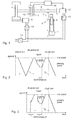
- Figure 2 shows how the speed is varied over time during a press cycle for a typical hybrid press.
- Time is gained because during opening and closing of the press a speed is used that is higher than the pressing speed.
- the speed is typically the same or lower in the hybrid press compared to the traditional mechanical press.
- the die-protection position a security check is made to ensure that the loader or unloader is no longer inside the press. Should the loader or unloader still be in the press, the press will perform an emergency stop. Failure to do so would result in a collision between the loader or unloader equipment and the press. This would not only damage the loader (or at least part of the loader), but also the press die. Since the press die is the most expensive part in this context, the position is referred to as "die protect".
- Unload cam position is the point where the press has opened sufficiently to allow the unloader to enter the press. While unload cam is determined purely geometrically, die protect has to take into account not only the geometry of the loader and the die, but also the braking distance of the press, since if the press starts braking at die protect, it should be able to stop before colliding with the loader.
- the auxiliary motor brings the press back from high speed to pressing speed before impact position.
- the clutch is engaged just before impact, at the moment the speed of the press and the flywheel speed are equal.
- the clutch is engaged without slipping, resulting in reduced wear and noise.
- the second motor is used such that the clutch is engaged in a synchronized way, i.e. when the speed of the flywheel and the speed of the press main shaft are almost or exactly equal.
- Synchronization between press and flywheel can be made such that a dented clutch can be used instead of a friction plate clutch, meaning that a more compact clutch can be used.
- a clutch may be cheaper, and has a lower inertia, which is advantageous for the press control.
- the press may not reach full speed before die protection position, when slowing down before impact, the deceleration has to be started very early to ensure that pressing speed is reached in time, when re-accelerating to high speed after pressing, full speed may not be reached before the press has to start the deceleration, when slowing down from high speed to a standstill, the deceleration may need to start before unload cam position so that standstill is reached in time, and during reversal, slowing down may take time that otherwise could have been used to re-accelerate the press for the next press cycle, possibly reaching a higher top speed.
- the object of the present invention is therefore to provide an attractive solution, which alleviates the problems above and thus reduces press cycle time and thereby increases productivity.
- the method is characterized in that it comprises engaging the clutch when the speed of the flywheel essentially differs from the speed of the press in order to change the speed of the press on one or more occasions during the press cycle.
- the clutch is actively used to change the speed of the press on one or more occasions during a press cycle.
- Engaging the clutch while the press is at a lower speed than the flywheel, including standstill and negative speed will result in rapid acceleration of the press towards pressing speed.
- Engaging the clutch while the press is at a higher speed than the flywheel will result in rapid deceleration of the press, towards pressing speed.
- the auxiliary motor may cooperate with the clutch to achieve even faster acceleration or deceleration, at the same time somewhat reducing the losses in the clutch. This enables the speed of the press to reach maximum speed earlier in the cycle than in the prior art, and to keep a high speed of the press during a longer part of the cycle, compared to the prior art, thereby reducing the press cycle time.
- the method comprises engaging the clutch while the press is at a higher speed than the flywheel in order to decelerate the press.
- the method comprises engaging the clutch at a point in time before the moment of impact such that the press is slowed down to a desired pressing speed before impact.
- the flywheel is connected to the press mechanics, in addition to the second motor, before the moment of impact.
- the clutch is used to rapidly decrease the speed of the press before the moment of impact.
- the method comprises engaging the clutch at a point in time after an unloader has permission to enter the press in order to slow down the press.
- An unloader is a mechanical unit, such as an industrial robot, which unloads the pressed object.
- the large inertia of the press makes it in some cases necessary to start slowing down the press before the point in time when the unloader enters the press, i.e. the unload cam position, in order to be able to stop in time or to be able to reach high speed before passing die-protect position at the beginning of the next cycle.
- Using the clutch to slow down the press to pressing speed then using the motor to further decrease speed (and optionally reverse) makes it possible to let the press have a higher speed before and until reaching the unload cam position.
- the press also comprises a brake.
- the method comprises engaging the brake at a point in time after an unloader has entered the press in order to slow down the speed of the press.
- the brake can be used independently of the clutch.
- the brake can be used during any part of the time between the unload cam position and the die-protection position, during which the press is slowing down, starting at any speed desired to slow down towards zero. Thereby, the slowdown of the press is made more rapid. The result is shortening the time needed for the press to get ready for the next cycle, which allows the use of a higher speed before and after pressing, and/or to reach a high speed earlier after die-protection position or until unload cam position.
- the method comprises disengaging the clutch when the press has been decelerated to a certain speed and then engaging the brake to slow down the press towards standstill.
- the method comprises engaging the clutch while the press is at a lower speed than the flywheel in order to accelerate the press.
- the method comprises engaging the clutch at the beginning of the press cycle such that the press is accelerated from a standstill up to a desired pressing speed, and disengaging the clutch after the desired pressing speed has been reached.
- the motor might have pre-accelerated the press a bit before the clutch is engaged. This embodiment is used to rapidly reach pressing speed, after which the auxiliary motor can accelerate the press further. This will allow the press to reach a higher speed before pressing or to reach the maximum speed earlier than in the prior art, which will result in a shorter cycle time.
- a device for controlling a mechanical press as initially defined.
- Such a device comprises a control unit for controlling the engagement of the clutch, and is characterized in that the control unit is adapted to, on one or more occasions during a press cycle, engage the clutch when the speed of the flywheel essentially differs from the speed of the press in order to change the speed of the press.
- the flywheel can be used in combination with the second motor to urge the change of speed of the press. The connection of the flywheel makes it possible to achieve more rapid changes in the speed of the press, thereby achieving a more rapid acceleration and a more rapid deceleration of the press.
- FIG. 1 shows an example of a hybrid press suitable for being controlled by a method according to the present invention.
- the press comprises a slide 1, which is moved upward and downward with a press speed during a press cycle. Further, the press includes press mechanics 2 for actuating the motion of the press including a press gear 3 and an eccentric wheel or crank 4.
- the press gear is connected to a rotating shaft 6.
- a first motor 8 keeps a flywheel 9 running at constant speed.
- a clutch 10 connects the flywheel with the press mechanics via the shaft 6 upon engagement.
- the press also comprises a brake 11, which upon engagement reduces the speed of the shaft 6.
- the press further comprises a second motor 12, generally called an auxiliary motor, which is used for changing the speed of the press.
- the second motor 12 is connected to the rotating shaft 6 or any other point of the press mechanics.
- the press further comprises a rectifier 14, a first inverter 15 connected to the first motor 8 and a second inverter 16 connected to the second motor 16.
- a control system 18 includes a computer unit and software adapted to control the engagement and disengagement of the clutch 10, the speed of the second motor and the brake.
- the computer unit comprises appropriate hardware such as one or more processors, memory and communication means for running the software on the computer unit.
- the control system 18 is adapted to generate control signals to the clutch, the second motor and the brake.
- the control system 18 is, for example, a PLC, the control system of an industrial robot used for loading and unloading the press, or a robot controller, in which the robot controller controls both the press and the robot.
- the control system can be any type of computer such as a personal computer.
- Figure 2 shows a speed profile of a hybrid press controlled according to the prior art.
- the unload cam position is the point where the press has opened sufficiently to allow an unloader to enter the press.
- the opening speed of the press has to be slowed down to zero before the closing of the press can begin.
- the slowdown of the opening speed starts before the unload cam position is reached.
- the closing of the press begins and the press speed is increased until maximum speed has been reached.
- the die-protection position When the press reaches a certain position during the cycle, denoted the die-protection position, a security check is made to ensure that the loader or unloader is no longer inside the press.
- speed of the press is not directly relevant for the cycle time, since during this time typically the press has to wait for the unloading and loading robots to do their work.
- the part of the work cycle which does not depend on the press is marked in the figure with an arrow denoted T1. It is advantageous if the press is started before the loader has finished loading, such that the press passes the die-protect position as short time as possible after the loader has left the press.
- the press should have as high speed as possible at the die-protect position, in order to reduce the press cycle time.
- the second motor accelerates the press until it reaches a maximum speed.
- the maximum speed is reached after the die-protection position.
- the maximum press speed is maintained during a short period, where after the second motor decelerates the speed until a desired pressing speed has been obtained. It is important that pressing speed has been obtained before impact position.
- the clutch 10 is engaged just before impact, at the moment the press speed and the flywheel speed are equal.
- the clutch 10 is engaged during the pressing.
- the clutch is disengaged and the second motor tries to accelerate the speed up to maximum press speed.
- Maximum press speed is maintained for a short period. Before or when the unload cam position is reached, the second motor decelerates the speed and brings the press down to a standstill.
- the die-protect position is the point in the cycle where the loader must be out of the press, it is between the die-protect position and the unload-cam position that the speed of the press determines the duration of this part of the press cycle.
- the part of the work cycle which depends on the press is marked in the figure with an arrow denoted T2.
- Figure 3 shows an example of a speed profile of a hybrid press controlled by the method according to the present invention.
- the clutch is engaged on two occasions during the press cycle. Engaging the clutch while the press is at a lower speed than the flywheel will result in rapid acceleration of the press.
- the clutch is engaged at the beginning of the press cycle, in addition to the second motor thereby achieving a rapid acceleration of the press from a standstill up to pressing speed as shown in figure 3 . Thereafter the clutch is disengaged and the second motor accelerates the speed until maximum press speed has been reached. Comparing figure 1 and figure 2 shows that maximum press speed is obtained earlier in the press cycle in the example when the clutch has been engaged at the beginning of the press cycle.
- the second motor accelerates the press towards a high speed.
- the clutch can be used to slow down the press to pressing speed, and then the brake can be used to slow down the press to a standstill. This makes it possible to keep the maximum press speed until the moment of unload cam, thereby further reducing the cycle time.
- the method according to the invention may alternatively be used in combination with dimensioning the system for a higher top speed of the press (while keeping the same motor, and motor peak power, but changing the gear ratio between motor and press). If this higher top speed is chosen, the drive will typically once again not be able to reach maximum speed before die-protection position and will once again have to start deceleration before the unload-cam position, but since the top speed is higher the cycle time will be reduced.
- the clutch is engaged on two occasions during the press cycle.
- the clutch is engaged on one or two occasions during the press cycle.
- it is possible to engage the clutch on three or more occasion during the press cycle it is probably not beneficial to use the clutch more than twice in a cycle due to wear which will cause a need to replace certain parts of the clutch.
- the more occasions during the press cycle the clutch is engaged the shorter will be the lifetime of the clutch.
- the advantage of using the clutch is to be weighed against the time between needing to replace certain parts of the clutch.
- the brake can be engaged at either positive or negative speed.
- the brake of a traditional mechanical press is dimensioned to bring the press down from pressing speed to zero once during every press cycle.
- one application of this method is to use the clutch to slow down the press to pressing speed just before impact, as shown in figure 3 .
- This has a direct impact on the cycle time of the press, since it allows the press to remain at high speed before pressing during longer part of the cycle. This is possible without significantly affecting the dimensioning of the clutch, since the speed difference (maximum slip) between maximum press speed and minimum pressing speed is typically similar to the speed difference between a standstill and maximum pressing speed, for which the clutch is dimensioned.
- the clutch would be used once during every cycle and the brake would not be used at all. However, the brake will be available for emergency stopping of the press.
- another embodiment of this method is to use the clutch to accelerate the press from standstill up to pressing speed at the beginning of the press cycle, as shown in figure 3 .
- the clutch After reaching pressing speed, the clutch would be disengaged, allowing the auxiliary motor to bring the press up to high speed. Before impact, the clutch would be engaged a second time, either after decelerating using the auxiliary motor or as described in the previous paragraph. This would allow the press drive to be dimensioned for reaching a higher maximum speed and/or to reach maximum speed earlier during the cycle and/or to start braking at a later point near the end of the cycle.
- the clutch may be engaged while the press is moving at negative speed, to rapidly increase press speed to positive pressing speed.
- the clutch may be engaged when the press is at or near the unload cam position. This will result in rapid slowdown from a high speed down to pressing speed. As soon as pressing speed is reached, the clutch is once again disengaged, and the motor is used to further slow down and optionally reverse the press before starting a next press cycle.
- the brake may be used to slow down the press to a standstill at the very end of the press cycle.
- the brake may be engaged while the press is at high or maximum speed, or when the press is already at a lower speed.
- This embodiment can be combined with the previous embodiment, first using the clutch to slow down the press to pressing speed, and then using the brake to slow down the press to a standstill. In all cases the slowdown of the press is more rapid, which means that either higher maximum speed can be reached and/or that a maximum or high speed can be used during a larger part of the cycle.
- the brake would be disengaged, allowing the auxiliary motor to drive the press.
- the second motor may help the brake for faster braking and reduction of losses (regenerative braking).
- the brake may be of a mechanical type (non-regenerative), or any other type, including regenerative types.
- the clutch may be mechanical (activated by hydraulics, pneumatics, or electromagnetically), or electromagnetic (in which case it may recover energy that in a mechanical clutch would be lost while clutching)
- the brake is used to slow down the press to a standstill while reversing the press.
- the brake can be engaged either at a high reversing speed, or after the motor has reduced the reversing speed. As a result, the reversing can be faster. This will allow reversing over a large angle, which in turn allows the press to reach a higher maximum forward speed and/or maintaining maximum forward speed during a longer part of the cycle.
- the auxiliary motor may, and will typically assist the clutch or brake in changing the speed of the press. This will reduce the stress on the clutch and the brake. When slowing down and accelerating, this may improve the energy efficiency of the drive. There will be losses in clutch and/or brake whenever one of these is used without synchronizing first. Using the auxiliary motor will help to reduces these losses.
- the clutch and/or brake may be engaged directly when a speed change in a certain direction is desired, or after a part of this speed change has been realized using the auxiliary motor.
- the speed difference (slip) experience by the clutch and the brake will be smaller resulting in less wear and lower losses.
- the clutch may after engagement be disengaged before the speed change has been completed. This would allow more control over the press speed.
- a clutch or a brake may be used, the torque of which can be controlled dynamically, during the motion. This would result in more control over the speed of the press.
- the brake or the clutch may be controlled pneumatically, hydraulically or electrically. Different types of brakes or clutches may be used.
- the proposed method may be applied to different types of motion cycles than the ones described here.
- An example of such motion would be continuous operation, i.e. operation where the press does not once reach zero speed during a press cycle.
- continuous operation of the press even if the clutch and the brake are not used during operation (except during actual pressing, for which the clutch may be engaged in a synchronized manner or in the way as described in this application), the clutch may be used for initial start-up of the press and the brake may be used for final slowdown of the press.
- the control of the flywheel motor can be used to limit the power taken from the common power supply of these two motors.
- the power of the flywheel motor may be reduced to zero when the auxiliary motor is supplying power to the press.
- the power of the flywheel motor may be made negative when the auxiliary motor is supplying high power to the press.
- this energy may be stored in the flywheel by activating the flywheel motor. This will reduce the peak negative power sent to the common power supply of the two motors. Since the flywheel has a large inertia, this method or peak power limitation will have only minor effect on flywheel speed.
- the control of the clutch, the brake and auxiliary motor is advantageously synchronized with the motion of one or both of these, during at least part of the cycle.
- the control of the clutch and the brake may otherwise be dependent on the position or the speed of the press. Optimization of the press motion, including control of the motors, clutch and brake may be done offline or online.
Abstract
Description
- The present invention relates to a device and a method for controlling a mechanical press including press mechanics for actuating the motion of the press, a first motor adapted to keep a flywheel running at an essentially constant speed, a clutch adapted to upon engagement connect the flywheel to the press mechanics, a second motor connected to the press mechanics and adapted to change the speed of the press. The present invention is, for example, useful for large mechanical presses, such as used for pressing metal parts in the car industry. However, the method may be used in any mechanical press in which a flywheel and a clutch are present.
- In a traditional mechanical press, a single motor is used to keep a flywheel running at a constant speed. At the beginning of every press cycle, a clutch is engaged, which connects the flywheel with the press mechanics. This brings the press from a standstill up to a desired pressing speed. The selection of the pressing speed is important since the pressing speed affects the quality of the pressed objects. The press then runs at approximately constant speed during the complete cycle. At the end of the cycle, the clutch is disengaged and instead a brake is engaged. The brake brings the press down to a standstill. After unloading the pressed object and reloading a new workpiece into the press, the next cycle is started. The press cycle has two parts, a first part including the steps closing of the press, impact, pressing and opening of the press, and a second part including unloading and loading the press. The time of the first part of the press cycle depends on the time for controlling the press, and the second part depends on the time for loading and unloading the press with a work piece. Commonly, industrial robots are used for carrying out the loading and unloading process.
- A hybrid press is an improvement of the traditional mechanical press and includes a second auxiliary motor connected directly to the press mechanics. The auxiliary motor is used for speed changes of the press during the press cycle, such as accelerating the press from a standstill to a high speed, slowing down the press from the high speed to pressing speed, accelerating the press to high speed after pressing, slowing down the press from high speed to a standstill, and optionally revising the press to an earlier position before starting the next cycle. The auxiliary motor makes it possible to have a speed that is essentially higher than the pressing speed before and after the pressing, thereby achieving a shorter cycle time, resulting in a significant increase in productivity.
-
Figure 2 shows how the speed is varied over time during a press cycle for a typical hybrid press. Time is gained because during opening and closing of the press a speed is used that is higher than the pressing speed. During actual pressing, including the moment of impact between the upper die and the workpiece, the speed is typically the same or lower in the hybrid press compared to the traditional mechanical press. When the press reaches a certain position during the cycle, usually denoted the die-protection position, a security check is made to ensure that the loader or unloader is no longer inside the press. Should the loader or unloader still be in the press, the press will perform an emergency stop. Failure to do so would result in a collision between the loader or unloader equipment and the press. This would not only damage the loader (or at least part of the loader), but also the press die. Since the press die is the most expensive part in this context, the position is referred to as "die protect". - Unload cam position is the point where the press has opened sufficiently to allow the unloader to enter the press. While unload cam is determined purely geometrically, die protect has to take into account not only the geometry of the loader and the die, but also the braking distance of the press, since if the press starts braking at die protect, it should be able to stop before colliding with the loader.
- During the part of the motion before the die protection position and after the unload cam position, speed of the press is not directly relevant for the cycle time, since during this time typically the press has to wait for the unloading and loading robots to do their work. In a hybrid press, the auxiliary motor brings the press back from high speed to pressing speed before impact position. The clutch is engaged just before impact, at the moment the speed of the press and the flywheel speed are equal. Thus, the clutch is engaged without slipping, resulting in reduced wear and noise. It is to be noted that for known hybrid presses, the second motor is used such that the clutch is engaged in a synchronized way, i.e. when the speed of the flywheel and the speed of the press main shaft are almost or exactly equal. Synchronization between press and flywheel can be made such that a dented clutch can be used instead of a friction plate clutch, meaning that a more compact clutch can be used. Such a clutch may be cheaper, and has a lower inertia, which is advantageous for the press control.
- Since the press mechanics have a relatively large inertia, changing the speed of the press within a short time requires very high torque. For the largest presses used in the car industry, this would mean an auxiliary motor with a peak power of about 600 - 1000 kW. This should be compared to the size of the flywheel motor, which for these presses typically is 400 - 500 kW. Even with such a large motor, the time needed for acceleration and deceleration is not negligible, and significantly impacts the average speed and thus the cycle time. In particular when accelerating from a standstill to a high speed, the press may not reach full speed before die protection position, when slowing down before impact, the deceleration has to be started very early to ensure that pressing speed is reached in time, when re-accelerating to high speed after pressing, full speed may not be reached before the press has to start the deceleration, when slowing down from high speed to a standstill, the deceleration may need to start before unload cam position so that standstill is reached in time, and during reversal, slowing down may take time that otherwise could have been used to re-accelerate the press for the next press cycle, possibly reaching a higher top speed.
- All of these negatively effect the cycle time, and thus the productivity of the press. The way to minimize this is to increase the size of the auxiliary motor or motors, but this will increase the installation cost (motor(s), converter(s) and possibly grid connection). Also, a larger motor has higher rotor inertia, which will negatively affect the performance.
- The object of the present invention is therefore to provide an attractive solution, which alleviates the problems above and thus reduces press cycle time and thereby increases productivity.
- The method is characterized in that it comprises engaging the clutch when the speed of the flywheel essentially differs from the speed of the press in order to change the speed of the press on one or more occasions during the press cycle.
- According to the invention, the clutch is actively used to change the speed of the press on one or more occasions during a press cycle. Engaging the clutch while the press is at a lower speed than the flywheel, including standstill and negative speed, will result in rapid acceleration of the press towards pressing speed. Engaging the clutch while the press is at a higher speed than the flywheel will result in rapid deceleration of the press, towards pressing speed. At the same time, the auxiliary motor may cooperate with the clutch to achieve even faster acceleration or deceleration, at the same time somewhat reducing the losses in the clutch. This enables the speed of the press to reach maximum speed earlier in the cycle than in the prior art, and to keep a high speed of the press during a longer part of the cycle, compared to the prior art, thereby reducing the press cycle time.
- It is expected that a significant part of the installations of hybrid press drives would be on existing presses. These presses would already have a flywheel and a clutch installed, which clutch is fully capable of being engaged while a large speed difference exists between the flywheel and the press. Of course, for application of the method according to the invention, thermal dimensioning, life time considerations, and noise generation should be taken into account, noting that the clutch of a traditional mechanical press is dimensioned to bring the press from a standstill to highest pressing speed once during every press cycle, and all press mechanics are dimensioned to withstand rapid accelerations and decelerations in each press cycle.
- According to an embodiment of the invention, the method comprises engaging the clutch while the press is at a higher speed than the flywheel in order to decelerate the press. For example, the method comprises engaging the clutch at a point in time before the moment of impact such that the press is slowed down to a desired pressing speed before impact. The flywheel is connected to the press mechanics, in addition to the second motor, before the moment of impact. Thus, the clutch is used to rapidly decrease the speed of the press before the moment of impact.
- Thereby, the time for slowing down the press to the desired pressing speed is essentially reduced, which allows the use of a high speed before pressing during a longer part of the cycle. This also means that a higher top speed can be chosen. Both result in a reduction of cycle time.
- According to an embodiment of the invention, the method comprises engaging the clutch at a point in time after an unloader has permission to enter the press in order to slow down the press. An unloader is a mechanical unit, such as an industrial robot, which unloads the pressed object. Today, the large inertia of the press makes it in some cases necessary to start slowing down the press before the point in time when the unloader enters the press, i.e. the unload cam position, in order to be able to stop in time or to be able to reach high speed before passing die-protect position at the beginning of the next cycle. Using the clutch to slow down the press to pressing speed, then using the motor to further decrease speed (and optionally reverse) makes it possible to let the press have a higher speed before and until reaching the unload cam position.
- The press also comprises a brake. According to another embodiment of the invention, the method comprises engaging the brake at a point in time after an unloader has entered the press in order to slow down the speed of the press. The brake can be used independently of the clutch. For example, the brake can be used during any part of the time between the unload cam position and the die-protection position, during which the press is slowing down, starting at any speed desired to slow down towards zero. Thereby, the slowdown of the press is made more rapid. The result is shortening the time needed for the press to get ready for the next cycle, which allows the use of a higher speed before and after pressing, and/or to reach a high speed earlier after die-protection position or until unload cam position. In another embodiment of the invention the method comprises disengaging the clutch when the press has been decelerated to a certain speed and then engaging the brake to slow down the press towards standstill.
- According to an embodiment of the invention, the method comprises engaging the clutch while the press is at a lower speed than the flywheel in order to accelerate the press. For example, the method comprises engaging the clutch at the beginning of the press cycle such that the press is accelerated from a standstill up to a desired pressing speed, and disengaging the clutch after the desired pressing speed has been reached. It should be noted that the motor might have pre-accelerated the press a bit before the clutch is engaged. This embodiment is used to rapidly reach pressing speed, after which the auxiliary motor can accelerate the press further. This will allow the press to reach a higher speed before pressing or to reach the maximum speed earlier than in the prior art, which will result in a shorter cycle time.
- According to a further aspect of the invention, this object is achieved by a device for controlling a mechanical press as initially defined. Such a device comprises a control unit for controlling the engagement of the clutch, and is characterized in that the control unit is adapted to, on one or more occasions during a press cycle, engage the clutch when the speed of the flywheel essentially differs from the speed of the press in order to change the speed of the press. The flywheel can be used in combination with the second motor to urge the change of speed of the press. The connection of the flywheel makes it possible to achieve more rapid changes in the speed of the press, thereby achieving a more rapid acceleration and a more rapid deceleration of the press.
- The invention will now be explained more closely by the description of different embodiments of the invention and with reference to the appended figures.
-
Figure 1 shows an example of a mechanical hybrid press. -
Figure 2 shows an example of a speed profile of the hybrid press controlled according to the prior art. -
Figure 3 shows an example of a speed profile of a hybrid press controlled according to the present invention. -
Figure 1 shows an example of a hybrid press suitable for being controlled by a method according to the present invention. The press comprises aslide 1, which is moved upward and downward with a press speed during a press cycle. Further, the press includespress mechanics 2 for actuating the motion of the press including a press gear 3 and an eccentric wheel or crank 4. The press gear is connected to arotating shaft 6. Afirst motor 8 keeps aflywheel 9 running at constant speed. A clutch 10 connects the flywheel with the press mechanics via theshaft 6 upon engagement. The press also comprises abrake 11, which upon engagement reduces the speed of theshaft 6. The press further comprises asecond motor 12, generally called an auxiliary motor, which is used for changing the speed of the press. Thesecond motor 12 is connected to therotating shaft 6 or any other point of the press mechanics. The press further comprises arectifier 14, afirst inverter 15 connected to thefirst motor 8 and asecond inverter 16 connected to thesecond motor 16. - A
control system 18 includes a computer unit and software adapted to control the engagement and disengagement of the clutch 10, the speed of the second motor and the brake. The computer unit comprises appropriate hardware such as one or more processors, memory and communication means for running the software on the computer unit. Thecontrol system 18 is adapted to generate control signals to the clutch, the second motor and the brake. Thecontrol system 18 is, for example, a PLC, the control system of an industrial robot used for loading and unloading the press, or a robot controller, in which the robot controller controls both the press and the robot. However, the control system can be any type of computer such as a personal computer. -
Figure 2 shows a speed profile of a hybrid press controlled according to the prior art. The unload cam position is the point where the press has opened sufficiently to allow an unloader to enter the press. The opening speed of the press has to be slowed down to zero before the closing of the press can begin. As seen in the figure, the slowdown of the opening speed starts before the unload cam position is reached. When the speed has reached zero the closing of the press begins and the press speed is increased until maximum speed has been reached. - When the press reaches a certain position during the cycle, denoted the die-protection position, a security check is made to ensure that the loader or unloader is no longer inside the press. During a part of the press cycle, before the die protection position and after the unload cam position, speed of the press is not directly relevant for the cycle time, since during this time typically the press has to wait for the unloading and loading robots to do their work. The part of the work cycle which does not depend on the press is marked in the figure with an arrow denoted T1. It is advantageous if the press is started before the loader has finished loading, such that the press passes the die-protect position as short time as possible after the loader has left the press. Preferably, the press should have as high speed as possible at the die-protect position, in order to reduce the press cycle time.
- The second motor accelerates the press until it reaches a maximum speed. As seen in the figure, the maximum speed is reached after the die-protection position. The maximum press speed is maintained during a short period, where after the second motor decelerates the speed until a desired pressing speed has been obtained. It is important that pressing speed has been obtained before impact position. The clutch 10 is engaged just before impact, at the moment the press speed and the flywheel speed are equal. The clutch 10 is engaged during the pressing. When pressing has been completed, the clutch is disengaged and the second motor tries to accelerate the speed up to maximum press speed. Maximum press speed is maintained for a short period. Before or when the unload cam position is reached, the second motor decelerates the speed and brings the press down to a standstill. Since the die-protect position is the point in the cycle where the loader must be out of the press, it is between the die-protect position and the unload-cam position that the speed of the press determines the duration of this part of the press cycle. The part of the work cycle which depends on the press is marked in the figure with an arrow denoted T2.
-
Figure 3 shows an example of a speed profile of a hybrid press controlled by the method according to the present invention. In this embodiment the clutch is engaged on two occasions during the press cycle. Engaging the clutch while the press is at a lower speed than the flywheel will result in rapid acceleration of the press. In this example, the clutch is engaged at the beginning of the press cycle, in addition to the second motor thereby achieving a rapid acceleration of the press from a standstill up to pressing speed as shown infigure 3 . Thereafter the clutch is disengaged and the second motor accelerates the speed until maximum press speed has been reached. Comparingfigure 1 and figure 2 shows that maximum press speed is obtained earlier in the press cycle in the example when the clutch has been engaged at the beginning of the press cycle. - Engaging the clutch while the press is at a higher speed than the flywheel will result in rapid deceleration of the press. In this example, the clutch is also engaged a short moment before impact will occur, thereby achieving a fast slowdown of the press to the desired pressing speed. The clutch is kept engaged during pressing. Comparing
figure 2 and 3 shows that it is possible to keep the maximum press speed during a longer part of the cycle due to the fast slowdown before impact. - After pressing, the second motor accelerates the press towards a high speed. In another embodiment, the clutch can be used to slow down the press to pressing speed, and then the brake can be used to slow down the press to a standstill. This makes it possible to keep the maximum press speed until the moment of unload cam, thereby further reducing the cycle time.
- The method according to the invention may alternatively be used in combination with dimensioning the system for a higher top speed of the press (while keeping the same motor, and motor peak power, but changing the gear ratio between motor and press). If this higher top speed is chosen, the drive will typically once again not be able to reach maximum speed before die-protection position and will once again have to start deceleration before the unload-cam position, but since the top speed is higher the cycle time will be reduced.
- In the example shown in
figure 3 , the clutch is engaged on two occasions during the press cycle. Preferably, the clutch is engaged on one or two occasions during the press cycle. Although it is possible to engage the clutch on three or more occasion during the press cycle, it is probably not beneficial to use the clutch more than twice in a cycle due to wear which will cause a need to replace certain parts of the clutch. The more occasions during the press cycle the clutch is engaged, the shorter will be the lifetime of the clutch. Thus, the advantage of using the clutch is to be weighed against the time between needing to replace certain parts of the clutch. - It is advantageous to use the brake for slowing down the press to a standstill. The brake can be engaged at either positive or negative speed. Although, it should be taken into account that the brake of a traditional mechanical press is dimensioned to bring the press down from pressing speed to zero once during every press cycle.
- As described above, one application of this method is to use the clutch to slow down the press to pressing speed just before impact, as shown in
figure 3 . This has a direct impact on the cycle time of the press, since it allows the press to remain at high speed before pressing during longer part of the cycle. This is possible without significantly affecting the dimensioning of the clutch, since the speed difference (maximum slip) between maximum press speed and minimum pressing speed is typically similar to the speed difference between a standstill and maximum pressing speed, for which the clutch is dimensioned. In this case, the clutch would be used once during every cycle and the brake would not be used at all. However, the brake will be available for emergency stopping of the press. - As described above, another embodiment of this method is to use the clutch to accelerate the press from standstill up to pressing speed at the beginning of the press cycle, as shown in
figure 3 . After reaching pressing speed, the clutch would be disengaged, allowing the auxiliary motor to bring the press up to high speed. Before impact, the clutch would be engaged a second time, either after decelerating using the auxiliary motor or as described in the previous paragraph. This would allow the press drive to be dimensioned for reaching a higher maximum speed and/or to reach maximum speed earlier during the cycle and/or to start braking at a later point near the end of the cycle. - In a case where the press reverses between consecutive press cycles, the clutch may be engaged while the press is moving at negative speed, to rapidly increase press speed to positive pressing speed. The same advantages as in the previously described applications are obtained, to an even higher degree.
- In another embodiment, the clutch may be engaged when the press is at or near the unload cam position. This will result in rapid slowdown from a high speed down to pressing speed. As soon as pressing speed is reached, the clutch is once again disengaged, and the motor is used to further slow down and optionally reverse the press before starting a next press cycle.
- In a further embodiment, the brake may be used to slow down the press to a standstill at the very end of the press cycle. The brake may be engaged while the press is at high or maximum speed, or when the press is already at a lower speed. This embodiment can be combined with the previous embodiment, first using the clutch to slow down the press to pressing speed, and then using the brake to slow down the press to a standstill. In all cases the slowdown of the press is more rapid, which means that either higher maximum speed can be reached and/or that a maximum or high speed can be used during a larger part of the cycle. As soon as standstill is reached, the brake would be disengaged, allowing the auxiliary motor to drive the press. The second motor may help the brake for faster braking and reduction of losses (regenerative braking).
- The brake may be of a mechanical type (non-regenerative), or any other type, including regenerative types.
- The clutch may be mechanical (activated by hydraulics, pneumatics, or electromagnetically), or electromagnetic (in which case it may recover energy that in a mechanical clutch would be lost while clutching)
- In yet another embodiment, the brake is used to slow down the press to a standstill while reversing the press. The brake can be engaged either at a high reversing speed, or after the motor has reduced the reversing speed. As a result, the reversing can be faster. This will allow reversing over a large angle, which in turn allows the press to reach a higher maximum forward speed and/or maintaining maximum forward speed during a longer part of the cycle.
- The proposed embodiments can in many cases advantageously be combined, however taking into account that multiple clutch and/or brake engagements during each cycle will cause wear and thus reduce the lifetime of the clutch and the brake, respectively.
- In all proposed embodiments, the auxiliary motor may, and will typically assist the clutch or brake in changing the speed of the press. This will reduce the stress on the clutch and the brake. When slowing down and accelerating, this may improve the energy efficiency of the drive. There will be losses in clutch and/or brake whenever one of these is used without synchronizing first. Using the auxiliary motor will help to reduces these losses.
- In all proposed embodiments, the clutch and/or brake may be engaged directly when a speed change in a certain direction is desired, or after a part of this speed change has been realized using the auxiliary motor. By first using the motor, the speed difference (slip) experience by the clutch and the brake will be smaller resulting in less wear and lower losses.
- In yet another embodiment, the clutch may after engagement be disengaged before the speed change has been completed. This would allow more control over the press speed.
- In a further embodiment, a clutch or a brake may be used, the torque of which can be controlled dynamically, during the motion. This would result in more control over the speed of the press. The brake or the clutch may be controlled pneumatically, hydraulically or electrically. Different types of brakes or clutches may be used.
- The proposed method may be applied to different types of motion cycles than the ones described here. An example of such motion would be continuous operation, i.e. operation where the press does not once reach zero speed during a press cycle. For continuous operation of the press, even if the clutch and the brake are not used during operation (except during actual pressing, for which the clutch may be engaged in a synchronized manner or in the way as described in this application), the clutch may be used for initial start-up of the press and the brake may be used for final slowdown of the press.
- In all cases where the auxiliary motor is supplying power to the press, the control of the flywheel motor can be used to limit the power taken from the common power supply of these two motors. In particular, the power of the flywheel motor may be reduced to zero when the auxiliary motor is supplying power to the press. Alternatively, the power of the flywheel motor may be made negative when the auxiliary motor is supplying high power to the press.
- Similarly, when the auxiliary motor is taking power from the press, this energy may be stored in the flywheel by activating the flywheel motor. This will reduce the peak negative power sent to the common power supply of the two motors. Since the flywheel has a large inertia, this method or peak power limitation will have only minor effect on flywheel speed.
- Since the press has to interact with the loader and unloader, typically robots, the control of the clutch, the brake and auxiliary motor is advantageously synchronized with the motion of one or both of these, during at least part of the cycle. The control of the clutch and the brake may otherwise be dependent on the position or the speed of the press. Optimization of the press motion, including control of the motors, clutch and brake may be done offline or online.
Claims (14)
- A method for controlling a mechanical press (1) including press mechanics (2) for actuating the motion of the press, a first motor (8) adapted to keep a flywheel (9) running at an essentially constant speed, a clutch (10) adapted, upon engagement, to connect the flywheel to the press mechanics, a second motor (12) connected to the press mechanics and adapted to change the speed of the press during a press cycle, characterized in that the method comprises engaging the clutch when the speed of the flywheel essentially differs from the speed of the press in order to change the speed of the press at one or more occasions during the press cycle.
- The method according to claim 1, wherein the method comprises engaging the clutch (10) while the press is at a higher speed than the flywheel in order to decelerate the press.
- The method according to claim 2, wherein the press cycle includes a moment of impact, and the method comprises engaging the clutch (10) at a point in time before the moment of impact such that the press is slowed down to a desired pressing speed before impact.
- The method according to claim 2 or 3, wherein the method comprises engaging the clutch (10) at a point in time after an unloader has permission to enter the press in order to slow down the press.
- The method according to any of the previous claims, wherein the press comprises a brake (11), and the method comprises engaging the brake at a point in time after an unloader has permission to enter the press in order to slow down the press.
- The method according to any of the previous claims, wherein the method comprises engaging the clutch (10) while the press is at a lower speed than the flywheel in order to accelerate the press.
- The method according to claim 6, wherein the method comprises engaging the clutch (10) at the beginning of the press cycle in order to accelerate the press from a standstill up to a desired pressing speed, and disengaging the clutch after the desired pressing speed has been reached.
- A device for controlling a mechanical press (1) including press mechanics (2) for actuating the motion of the press, a first motor (8) adapted to keep a flywheel (9) running at an essentially constant speed, a clutch (10) adapted, upon engagement, to connect the flywheel to the press mechanics, a second motor (12) connected to the press mechanics and adapted to change the speed of the press during a press cycle, wherein the device comprises a control unit (18) for controlling the engagement of the clutch, characterized in that the control unit, on one or more occasions during the press cycle, is adapted to engage the clutch when the speed of the flywheel essentially differs from the speed of the press in order to change the speed of the press.
- The device according to claim 8, wherein the control unit (18) is adapted to engage the clutch (10) while the press (1) is at a higher speed than the flywheel (9) in order to decelerate the press.
- The device according to claim 9, wherein the press cycle includes an impact, and the control unit (18) is adapted to engage the clutch at a point in time before the moment of impact such that the press is slowed down to a desired pressing speed before impact.
- The device according to claim 8 or 9, wherein the control unit (18) is adapted to engage the clutch at a point in time after an unloader has permission to enter the press so that the press is slowed down.
- The device according to claim 11, wherein the press comprises a brake (11), and the control unit (18) is adapted to engage the brake at a point in time after an unloader has permission to enter the press in order to slow down the press.
- The device according to any of the claims 8-12, wherein the control unit (18) is adapted to engage the clutch while the press is at a lower speed than the flywheel in order to accelerate the press.
- The device according to claim 3, wherein the control unit (18) is adapted to engage the clutch at the beginning of the press cycle in order to accelerate the press to a desired pressing speed, and to disengage the clutch after the desired pressing speed has been reached.
Priority Applications (2)
| Application Number | Priority Date | Filing Date | Title |
|---|---|---|---|
| EP07110739A EP2006080A1 (en) | 2007-06-21 | 2007-06-21 | A method and device for controlling a mechanical press |
| PCT/EP2008/056363 WO2008155190A1 (en) | 2007-06-21 | 2008-05-23 | A method and a device for controlling a mechanical press |
Applications Claiming Priority (1)
| Application Number | Priority Date | Filing Date | Title |
|---|---|---|---|
| EP07110739A EP2006080A1 (en) | 2007-06-21 | 2007-06-21 | A method and device for controlling a mechanical press |
Publications (1)
| Publication Number | Publication Date |
|---|---|
| EP2006080A1 true EP2006080A1 (en) | 2008-12-24 |
Family
ID=38669239
Family Applications (1)
| Application Number | Title | Priority Date | Filing Date |
|---|---|---|---|
| EP07110739A Withdrawn EP2006080A1 (en) | 2007-06-21 | 2007-06-21 | A method and device for controlling a mechanical press |
Country Status (2)
| Country | Link |
|---|---|
| EP (1) | EP2006080A1 (en) |
| WO (1) | WO2008155190A1 (en) |
Cited By (2)
| Publication number | Priority date | Publication date | Assignee | Title |
|---|---|---|---|---|
| WO2011152742A2 (en) | 2010-06-01 | 2011-12-08 | Uniwersytet Przyrodniczy W Poznaniu | Feed additive of antimicrobial properties, concentrate, use of feed additive to obtain concentrate and method of manufacturing feed additive |
| DE102010049492A1 (en) * | 2010-10-27 | 2012-05-03 | Schuler Pressen Gmbh | Mechanical forming machine, in particular crank press and method for providing a mechanical forming machine |
Families Citing this family (2)
| Publication number | Priority date | Publication date | Assignee | Title |
|---|---|---|---|---|
| JP5770586B2 (en) * | 2011-09-28 | 2015-08-26 | 住友重機械工業株式会社 | Forging press apparatus and control method thereof |
| EP3315267B1 (en) * | 2016-10-25 | 2019-12-04 | Siemens Aktiengesellschaft | Method for optimizing of movement profiles, method for providing movement profiles, control device, system and computer program product |
Citations (8)
| Publication number | Priority date | Publication date | Assignee | Title |
|---|---|---|---|---|
| DE884278C (en) * | 1941-07-17 | 1953-07-27 | Weingarten Ag Maschf | Mechanical press, especially drawing press |
| DE949863C (en) * | 1941-07-17 | 1956-09-27 | Weingarten Ag Maschf | Mechanical press, especially drawing press |
| DE1294809B (en) * | 1961-01-14 | 1969-05-08 | Pressen Und Scherenbau Erfurt | Press drive with different working speeds for mechanical presses, especially drawing presses |
| US4150616A (en) * | 1977-06-28 | 1979-04-24 | L. Schuler Gmbh | Method of controlling the speed of a mechanical press |
| JPS5970497A (en) * | 1982-10-14 | 1984-04-20 | Aida Eng Ltd | Variable speed driving device for press |
| DE29906519U1 (en) * | 1999-04-13 | 1999-08-12 | Desch Antriebstechnik Gmbh & Co Kg | Drive for a mechanical press |
| US20040003729A1 (en) * | 2002-07-04 | 2004-01-08 | Komatsu Artec Ltd. | Drive unit and drive method for press |
| EP1640145A1 (en) * | 2004-09-27 | 2006-03-29 | Burkhardt GmbH Maschinenfabrik | Direct drive and control for eccentric press |
-
2007
- 2007-06-21 EP EP07110739A patent/EP2006080A1/en not_active Withdrawn
-
2008
- 2008-05-23 WO PCT/EP2008/056363 patent/WO2008155190A1/en active Application Filing
Patent Citations (8)
| Publication number | Priority date | Publication date | Assignee | Title |
|---|---|---|---|---|
| DE884278C (en) * | 1941-07-17 | 1953-07-27 | Weingarten Ag Maschf | Mechanical press, especially drawing press |
| DE949863C (en) * | 1941-07-17 | 1956-09-27 | Weingarten Ag Maschf | Mechanical press, especially drawing press |
| DE1294809B (en) * | 1961-01-14 | 1969-05-08 | Pressen Und Scherenbau Erfurt | Press drive with different working speeds for mechanical presses, especially drawing presses |
| US4150616A (en) * | 1977-06-28 | 1979-04-24 | L. Schuler Gmbh | Method of controlling the speed of a mechanical press |
| JPS5970497A (en) * | 1982-10-14 | 1984-04-20 | Aida Eng Ltd | Variable speed driving device for press |
| DE29906519U1 (en) * | 1999-04-13 | 1999-08-12 | Desch Antriebstechnik Gmbh & Co Kg | Drive for a mechanical press |
| US20040003729A1 (en) * | 2002-07-04 | 2004-01-08 | Komatsu Artec Ltd. | Drive unit and drive method for press |
| EP1640145A1 (en) * | 2004-09-27 | 2006-03-29 | Burkhardt GmbH Maschinenfabrik | Direct drive and control for eccentric press |
Cited By (5)
| Publication number | Priority date | Publication date | Assignee | Title |
|---|---|---|---|---|
| WO2011152742A2 (en) | 2010-06-01 | 2011-12-08 | Uniwersytet Przyrodniczy W Poznaniu | Feed additive of antimicrobial properties, concentrate, use of feed additive to obtain concentrate and method of manufacturing feed additive |
| DE102010049492A1 (en) * | 2010-10-27 | 2012-05-03 | Schuler Pressen Gmbh | Mechanical forming machine, in particular crank press and method for providing a mechanical forming machine |
| WO2012055558A1 (en) * | 2010-10-27 | 2012-05-03 | Schuler Pressen Gmbh | Mechanical metal-forming machine, in particular a crank press, and method for providing a mechanical metal-forming machine |
| DE102010049492B4 (en) * | 2010-10-27 | 2013-04-18 | Schuler Pressen Gmbh | Mechanical forming machine, in particular crank press and method for providing a mechanical forming machine |
| US9350212B2 (en) | 2010-10-27 | 2016-05-24 | Schuler Pressen Gmbh | Mechanical metal-forming machine having a flywheel coupled to a rotor of an auxiliary drive and method for providing the mechanical metal-forming machine |
Also Published As
| Publication number | Publication date |
|---|---|
| WO2008155190A1 (en) | 2008-12-24 |
Similar Documents
| Publication | Publication Date | Title |
|---|---|---|
| EP1981701B1 (en) | Mechanical press drive system | |
| KR101211985B1 (en) | Mechanical press drive system and method | |
| US8220384B2 (en) | Motor upgrade kit for a mechanical press | |
| JP5555679B2 (en) | Servo press and servo press control method | |
| CN101674930B (en) | Press machine and method of controlling the same | |
| EP2006080A1 (en) | A method and device for controlling a mechanical press | |
| WO2007091964A2 (en) | Press line system and method | |
| US6193625B1 (en) | Ram speed control method and apparatus | |
| JP5265533B2 (en) | Improved method and system for coordinating and operating a cyclic manufacturing machine with a loader or unloader machine | |
| CN112253389B (en) | Start-stop control method for yaw control system of wind generating set | |
| JP2009285666A (en) | Servo press arrangement and its control method | |
| US6474227B2 (en) | Method of controlling synchronous drive of pressing machine and pressing machine usable in the method | |
| Bosga et al. | New drive concepts reduce power requirements of large servo presses | |
| JP5327704B2 (en) | Mechanical press regenerative braking device and method | |
| CN111152493A (en) | High-energy screw press of gear drive clutch | |
| Bosga et al. | Design and tests of a hybrid servo drive system for a 1000 T mechanical press | |
| Bosga et al. | Servo drives introduce improved synchronization of large presses with robots | |
| US20230294158A1 (en) | Method for operating a servo motor driven turning station of a stacking tool for a punch press | |
| JP2023095424A (en) | Press device and press method | |
| KR20110122770A (en) | Mechanical press drive system and method | |
| MXPA01001882A (en) | Method of controlling synchronous drive of pressing machine and pressing machine usable in the method |
Legal Events
| Date | Code | Title | Description |
|---|---|---|---|
| PUAI | Public reference made under article 153(3) epc to a published international application that has entered the european phase |
Free format text: ORIGINAL CODE: 0009012 |
|
| AK | Designated contracting states |
Kind code of ref document: A1 Designated state(s): AT BE BG CH CY CZ DE DK EE ES FI FR GB GR HU IE IS IT LI LT LU LV MC MT NL PL PT RO SE SI SK TR |
|
| AX | Request for extension of the european patent |
Extension state: AL BA HR MK RS |
|
| 17P | Request for examination filed |
Effective date: 20090115 |
|
| AKX | Designation fees paid |
Designated state(s): AT BE BG CH CY CZ DE DK EE ES FI FR GB GR HU IE IS IT LI LT LU LV MC MT NL PL PT RO SE SI SK TR |
|
| 17Q | First examination report despatched |
Effective date: 20100827 |
|
| STAA | Information on the status of an ep patent application or granted ep patent |
Free format text: STATUS: THE APPLICATION IS DEEMED TO BE WITHDRAWN |
|
| 18D | Application deemed to be withdrawn |
Effective date: 20110103 |