EP2005388B1 - Automatische interpretation von medizinischen 3d-bildern des hirns und verfahren zum produzieren von zwischenergebnissen - Google Patents
Automatische interpretation von medizinischen 3d-bildern des hirns und verfahren zum produzieren von zwischenergebnissen Download PDFInfo
- Publication number
- EP2005388B1 EP2005388B1 EP07727363A EP07727363A EP2005388B1 EP 2005388 B1 EP2005388 B1 EP 2005388B1 EP 07727363 A EP07727363 A EP 07727363A EP 07727363 A EP07727363 A EP 07727363A EP 2005388 B1 EP2005388 B1 EP 2005388B1
- Authority
- EP
- European Patent Office
- Prior art keywords
- brain
- image
- images
- points
- point
- Prior art date
- Legal status (The legal status is an assumption and is not a legal conclusion. Google has not performed a legal analysis and makes no representation as to the accuracy of the status listed.)
- Active
Links
Images


Classifications
-
- G—PHYSICS
- G06—COMPUTING OR CALCULATING; COUNTING
- G06T—IMAGE DATA PROCESSING OR GENERATION, IN GENERAL
- G06T7/00—Image analysis
- G06T7/0002—Inspection of images, e.g. flaw detection
- G06T7/0012—Biomedical image inspection
-
- G—PHYSICS
- G06—COMPUTING OR CALCULATING; COUNTING
- G06T—IMAGE DATA PROCESSING OR GENERATION, IN GENERAL
- G06T7/00—Image analysis
- G06T7/10—Segmentation; Edge detection
- G06T7/12—Edge-based segmentation
-
- G—PHYSICS
- G06—COMPUTING OR CALCULATING; COUNTING
- G06T—IMAGE DATA PROCESSING OR GENERATION, IN GENERAL
- G06T7/00—Image analysis
- G06T7/10—Segmentation; Edge detection
- G06T7/149—Segmentation; Edge detection involving deformable models, e.g. active contour models
-
- G—PHYSICS
- G06—COMPUTING OR CALCULATING; COUNTING
- G06V—IMAGE OR VIDEO RECOGNITION OR UNDERSTANDING
- G06V10/00—Arrangements for image or video recognition or understanding
- G06V10/70—Arrangements for image or video recognition or understanding using pattern recognition or machine learning
- G06V10/74—Image or video pattern matching; Proximity measures in feature spaces
- G06V10/75—Organisation of the matching processes, e.g. simultaneous or sequential comparisons of image or video features; Coarse-fine approaches, e.g. multi-scale approaches; using context analysis; Selection of dictionaries
- G06V10/755—Deformable models or variational models, e.g. snakes or active contours
- G06V10/7553—Deformable models or variational models, e.g. snakes or active contours based on shape, e.g. active shape models [ASM]
-
- G—PHYSICS
- G06—COMPUTING OR CALCULATING; COUNTING
- G06T—IMAGE DATA PROCESSING OR GENERATION, IN GENERAL
- G06T2207/00—Indexing scheme for image analysis or image enhancement
- G06T2207/10—Image acquisition modality
- G06T2207/10072—Tomographic images
- G06T2207/10108—Single photon emission computed tomography [SPECT]
-
- G—PHYSICS
- G06—COMPUTING OR CALCULATING; COUNTING
- G06T—IMAGE DATA PROCESSING OR GENERATION, IN GENERAL
- G06T2207/00—Indexing scheme for image analysis or image enhancement
- G06T2207/20—Special algorithmic details
- G06T2207/20112—Image segmentation details
- G06T2207/20124—Active shape model [ASM]
-
- G—PHYSICS
- G06—COMPUTING OR CALCULATING; COUNTING
- G06T—IMAGE DATA PROCESSING OR GENERATION, IN GENERAL
- G06T2207/00—Indexing scheme for image analysis or image enhancement
- G06T2207/20—Special algorithmic details
- G06T2207/20112—Image segmentation details
- G06T2207/20128—Atlas-based segmentation
-
- G—PHYSICS
- G06—COMPUTING OR CALCULATING; COUNTING
- G06T—IMAGE DATA PROCESSING OR GENERATION, IN GENERAL
- G06T2207/00—Indexing scheme for image analysis or image enhancement
- G06T2207/30—Subject of image; Context of image processing
- G06T2207/30004—Biomedical image processing
- G06T2207/30016—Brain
-
- G—PHYSICS
- G06—COMPUTING OR CALCULATING; COUNTING
- G06V—IMAGE OR VIDEO RECOGNITION OR UNDERSTANDING
- G06V2201/00—Indexing scheme relating to image or video recognition or understanding
- G06V2201/03—Recognition of patterns in medical or anatomical images
Definitions
- the present invention relates to the field of processing and interpreting medical images.
- Diagnosing based on 3-D nuclear images of the brain is difficult and time demanding and relies on visual interpretation and numerical quantification of the images.
- the existing systems for displaying and quantifying such images bring a lot of manual work for the physician which may have to mark region(s) of interests with geometrical templates. This takes a lot of time and the accuracy of the segmentation is poor.
- SE 2020565 discloses a metod and a device for determining of a three dimensional contour of an organ in a patients body, starting from an image of said organ.
- the method comprises a step of adjusting a predefined contour model to the image of said organ.
- the object of the present invention is therefore to provide a method for reducing the need for manual work to create an image fully comparable with a normal reference image.
- NICOLAE DUTA ET AL "Segmentation and Interpretation of MR Brain Images: An Improved Active Shape Model" IEEE TRANSACTIONS ON MEDICAL IMAGING, IEEE SERVICE CENTER, PISCATAWAY, NJ, US, vol. 17, no. 6, December 1998 (1998-12), XP011035793 ISSN: . 0278-0062 discloses that a training set of eight brain images was used to build a model, and is based on Point Distribution Models, and all the images are normalised prior to training using the threedimensional Talairach grid.
- the present invention provides a method for creating a brain shape model as disclosed in claim 1.
- 3D image refers to a representation of a three dimensional object.
- the representation is mostly digital, comprising a number of 3D pixels , here called voxels, each voxel having a value representing an intensity value captured by an imaging device , and corresponding to each object voxel, when generating the image of the object.
- Suitable 3D images can be generated, for example, by SPECT cameras, and MRI cameras.
- CBF Cerebral blood flow
- Contour finding refers to the activity of finding, in a representation of a three dimensional object, the contour of the object. In the case of the present invention, it refers to the activity of finding the contour of a body organ, i.e., finding a surface that defines the outer contour of the body organ, in particular the brain.
- Image rotation refers to the activity of aligning a 3D image of an organ such that the organ is oriented in relationship to a localx, y and z-axes according to some convention. coordinate system of the organ is aligned to an external coordinate system comprising a viewpoint for creating viewable images.
- the outline refers to the contour of an object.
- PCA Principal Component Analysis.
- Reference angle refers to an angle expressing how an image volume should be rotated to achieve a standardised orientation.
- Segmentation refers to the activity of adjusting a shape model such that said shape model coincides, or approximately coincides as good as the used method allows, with the shape of an image of a particular organ of a particular patient.
- segmentation also refers to the activity of partitioning an digital image into two or more regions. Here it also refers to the activity of partitioning, in a representation of a three dimensional organ, the surface of the organ such that resulting partitions is corresponding to partitions of a reference data set.
- the methods are intended for 3-D nuclear medicine images of the brain, such as Single Photon Emission Computed Tomography (SPECT) and Positron Emission Tomography (PET) images, representing for example cerebral blood flow (CBF) or receptor density. It may also be applicable for other types of images of the brain or other organs for which the diagnostic procedure is similar.
- SPECT Single Photon Emission Computed Tomography
- PET Positron Emission Tomography
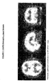
- An example includes a method for automatic rotation of the brain image. Differences in rotation of the brain image are due to head tilting of the patient and the largest variations usually appear in the sagittal view. Today, this is a step that is done manually by the scanner operator before the physician starts reviewing the images. The automatic method gives a suggestion of the rotation which in most cases only need to be approved by the physician. Another advantage is that the automatic rotation becomes more consistent compared to the manual, since different operators do this step differently. The automatic rotation is necessary both for displaying the slice images with a proper rotation for reviewing and for the Active Shape based segmentation described below.
- PCA Principal Component Analysis
- a few suitable sample slices in each view are chosen. Since brain images are relatively symmetrical around the y-axis in the transaxial view, this is the first view that is considered. Three to five slices, with two to three pixels separation, around the middle transaxial slice are collected. The middle slice refers to the slice that represents the middle of the brain. Gray-level thresholding is applied on the sample slices. It is a simple image processing operation which steps through all the pixels of the image and assigns 1 or 0 depending on if the original pixel value is above or below a threshold value.
- the next view to consider is the sagittal view, which is the most important one since it has the largest variation in rotation.
- the transaxial sample slices are used to locate the middle sagittal slice. From the collected points of the sample slices, representing brain tissue, the center of gravity is calculated. That is the mean coordinate of the pixels labeled 1 in the thresholded image.
- the x-coordinate of the center of gravity is equal to the middle sagittal slice and the y-coordinate is equal to the middle coronal slice.
- the reference angle for the coronal view is calculated.
- the direction of the largest variation can differ 90 degrees depending on which sample slices that are chosen and the shape of the brain. It is not clear whether the reference angle should be calculated from the x-axis or y-axis of the coronal view. It is however safe to assume that the reference angle should not be below -45 degress or above 45 degrees.
- the reference angles are calculated both from the x-axis and the y-axis for all the sample slices and the ones with the lowest absolute value are accepted.
- the mean angle is calculated from the reference angles of the sample slices and is used to rotate the image.
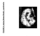
- ASMs Active Shape Models
- T.F. Cootes and C.J. Taylor Statistical Models of Appearance for Computer Vision, Wolfson Image Analysis Unit, Imaging Science and Biomedical Engineering, University of Manchester, 2000. p. 9-25, 34-38 , are used for segmentation of the brain surface. It can be described as a statistical contour model built of a database of examples (training datasets) of the object that is going to be segmented. The model consists of a mean shape and information about the statistical variation of the training set.
- Active Shape Models it is possible to segment the brain surface in a way that is superior to existing methods that demand manual placement of regions of interest.
- these regions of interest are segmented with geometrical template shapes that can be translated, scaled and rotated. That kind of segmentation is very limited.
- Active Shape Models give the contours of the brain with high precision which makes it possible to quantify the cortex (brain surface) with high accuracy.
- the cortex is where the most valuable diagnostic information is in CBF images.
- the datasets have been collected manually by marking landmarks in a certain order on the brain surface, slice by slice in the 3-D image.
- a database of patients with normal CBF was used for this matter.
- the sagittal view was chosen for clicking out the training examples. The reason for that is because the brain shape appears as one connected region in all slices.
- the brain parts can be divided into separated regions in some slices.
- a number of slices and a number of points have been defined for the model. In an example these numbers are 17 slices and 32 points plus one start and one end slice with one point each. This gives 546 points, or landmarks, for each training example for the construction of the ASM.
- a landmark is a point that has a specific position on the shape.
- a start slice, end slice and middle slice was chosen and the slices in between was spread out with equal space.
- the middle slice of the model is meant to lie between left and right brain.
- the points for each slice are clicked out in a way that is shown in the drawings.
- the point data is connected with triangles to form a mesh which can be used for calculation and 3D-visualization.
- the ASM is built and used as described by Cootes and Taylor.
- the Active Shape theory is generally known but to adapt it for a new type of images, in this case brain images, two problems need to be solved:
- the automatic rotation algorithm comes to use once more for deciding the orientation of the unknown brain image.
- the extension is calculated for one of the thresholded sample slices of the sagittal view by locating the extreme points. The points of the thresholded pixels of the sagittal slice are collected and the maximum and minimum x-coordinates are used. The extension in the x-direction is calculated by subtracting the mininum coordinate from the maximum.
- the model can be enlarged to roughly fit the brain surface by dividing the extension of the thresholded sample slice with the extension of the mean shape in the ASM. At this step the model only has the mean shape of the brains in the database that the model is built of.
- the next step is to adjust the shape of the model which is done iteratively.
- the normal is calculated, which is done by calculating the eight normals of the eight triangles that are formed by the point and its eight neighboring points in the model mesh.
- the normal vectors are perpendicular to the surface and are used to search for new landmarks to adjust the ASM to.
- the normals are scanned inwards and outwards to a certain distance from the surface and with a certain step size, sampling the intensity values of the image data.
- sample image data There are several ways to sample image data. In an example is used a linear sampling of the 27 pixels that surrounds the point. For CBF-SPECT images a step size of one pixel is enough. The distance should not be too long since it may result that points that have similar attributes as the brain surface are found. It should be as long that it is possible to reach the surface of the brain for at least some points in the first search from the initial guess. The point along the sample vector that is most likely to lie on the brain surface is chosen, which is done in the following way.
- the image data at the brain surface has two distinguish features:
- the algorithm uses the algorithm to decide which point that best matches the brain surface.
- the first criterion is simply the intensity value of the sampling.
- a derivative filter is applied on the sampled intensity data with discrete convolution, see for example1.
- the algorithm searches for the highest positive derivative. If no sample is in range of the first criterion the landmark of the point is not moved. New points are chosen for each landmark that matches the criteria.
- the ASM is fitted to the new points and the procedure is iteratively repeated until convergence or until no point moves more than for example one pixel.
- a brain atlas has been constructed for usage together with the shape model.
- the atlas defines which brain lobe each landmark belongs to and is used both for the automatic quantification and visualization of the brain lobes on the 3-D model.
- the brain atlas is based on images from MRI of the brain.
- the brain atlas was built manually by clicking out the landmarks of the ASM in an MRI image, in the same way as for the training examples of which the ASM was contructed by. Each landmark was labeled by a physician as belonging to one of the brain lobes or regions of the brain surface. The brain atlas is used together with the ASM to determine which points that for example belong to the frontal lobe.
- Brain images are usually normalized by the maximum intensity of the cerebellum, which is not always the maximum of the image volume. With the information of the brain atlas and the ASM, the maximum intensity of the cerebellum and its location can be decided. In the coordinate system of the transaxial view, the highest and lowest z-coordinates of the cerebellum points in the fitted model are used to limit the search for the maximum intensity value in the image volume. The image slices and 3-D brain are visualized with the normalization value as maximum intensity of the image volume.
- the mean intensity of the brain surface is calculated for each lobe. For the quantification the number of points in the model is increased by interpolation. Each triangle of the surface mesh is splitted into four triangles of equal size. Intensity values are sampled along the normals inwards from the brain surface. A sampling depth of 15 mm is used which corresponds to around 5-8 pixels depending on the image resolution. The maximum value of the sampling of each landmark is saved as intensity values.
- the mean intensity of a brain lobe is expressed with the mean intensity of the whole brain surface as reference.
- the brain atlas is used to extract the points of the model that belong to a specific lobe and the middle slice of the model is used to divide the lobes into right and left parts.
- the mean intensities of each lobe are calculated and divided with the mean intensity of the whole brain (the mean intensity of all the points on the brain surface).
- the quantification is used together with a reference database of patients with normal cerebral blood flow.
- the mean intensities for each point and each lobe and their standard deviations have been calculated for all the patients in the database.
- the result is used for comparison with new patients. Differences between a new patient and the normal database are expressed as number of standard deviations from normal mean value of the specific point or lobe (sometimes called z-score).
- the quantification results are presented in a table and used as inputs in the automatic classification of the patient.
- ANNs Artificial Neural Networks
- p. 1-111, p. 156-252, 351-389 or any other machine learning technique such as Support Vector Machines, are used for making the automatic interpretation and generate a computer-based diagnosis based on a large database of patients evaluated by experts in the field.
- Each patient in the database is labeled with one of the classes that are used. For example two classes can be used where class 1 is normal and class 2 is pathological.
- the quantification results as well as other features that are relevant for the diagnosis are used as input to the ANNs.
- the other features are obtained through image analysis and describe properties such as number of clusters with low intensity (for example a z-score below -2), their sizes and depths. It could also be non-image data such as the age and sex of the patient.
- the ANNs compare the quantification results and the features of the new patient with the patients of the database and by doing so the system can predict whether for example dementia occurs in CBF-SPECT images or not. It serves as a second opinion that complements the physician's own diagnosis.
- the brain images are displayed both as 2-D slices and as a 3-D flow model.
- the 2-D slice view includes a click orientation tool which makes it easy to navigate in the 3-D volume. When clicking on a spot in the image of one of the three views, the slices of the spot in the two other views appear together with a cross marking the position.
- the 3-D view shows the intensity values of the brain surface with a number of different color scales. It is possible to show the different lobes of the brain surface, on the 3-D brain. The user can choose to highlight or shadow a specified lobe of the brain surface.
- Another 3-D model shows the difference in standard deviations (z-score) from the normal reference database, where a z-score below -2 is shown in red and above 2 is shown in green. The results of the quantification are presented in a table together with the normal values of the reference database.
- the next step is to open a report panel and write a report.
- the physician Before creating the report the physician will get the diagnosis of the automatic interpretation. If it is the same as the physician's the diagnosis is secured, if not it encourage the physician to reconsider his or her interpretation.
- Slice images as well as 3-D images can be chosen to be included in the report.
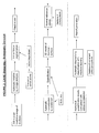
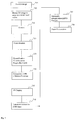
- Fig. 7 shows an overview flowchart of a method for computer aided diagnosis of 3D images of the brain. The method comprising the following steps:
- the representation comprises a number of 3D pixels , here called voxels, each voxel having a value representing an intensity value corresponding to an amount of some quality of the original object voxel.
- the method comprises the following steps:
- the second step comprises the following substeps:
- a method for determining a three dimensional contour of a brain is described.
- the boxes for steps A and B are shown with dashed contours to indicate that they do not form part of the method. They are instead performed as a preparation for the method, to provide input data.
- a first step A an image of a brain is created, the contour of which is to be determined, and which is to be presented, in a processed form, with information indicating possible abnormalities.
- the image may be generated by a brain scintigraphy apparatus or other image apparatus capable of generating functional images.
- a three dimensional image is obtained.
- the image of the brain is stored, as is schematically shown in fig.
- each image point comprises an intensity value.
- This image matrix is normally of the same dimensions each time a brain is depicted.
- a common size is 128 x 128 x 90 voxels: The image matrix is thus comprised of points, laying in a number of parallel planes.
- the intensity values in the image matrix may also be normalised at this point or later, see below.
- the image of the brain will land up approximately in the same place in the image matrix, each time. This means that there is no need for searching for the brain, but it is legitimate to assume that it is positioned approximately in the middle of the image matrix.
- step B a contour model is created.
- shape model will be used instead of “contour model” for the purpose of the present application.
- shape model is a cloud of points representing the shape of an organ, in this case the brain, and the term “brain shape model” will also be used for clarity.
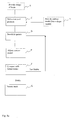
- the present invention provides method for creating a brain shape model is disclosed with reference to Figs 8b and 8 d , the method comprises the following steps:
- the method may further comprise the following steps:
- the positioned points, now constituting a cloud of points in a three diminsional space, is said to define the shape of each reference brain.
- the next step is to create a brain model shape by scaling and positioning B14 of each cloud of points B13, e.g., by least square method, and make statistical averages for each point in relation to the same point of the other reference brains. Also other statistical measures can be calculated, such as the standard deviation and the variance. Also other measures, such as a co-variance matrix may be calculated as is known in the art of Active Shape Models.
- the resulting cloud of points representing an average brain model shape is in the following referred to as the "brain shape model" and is denoted c'.
- the making of the brain shape model is normally done only once.
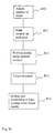
- an iterative method for adjusting the brain shape model to a particular image of a particular patient's brain comprises the following steps:
- the adjusted brain shape model c is further adjusted in an iterative process comprising the following steps:
- the model may now be refined, i.e., the number of points may be increased by interpolation, for example from approximately 600 to approximately 3500.
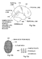
- each point have also been assigned to a brain lobe, for example the left and right: frontal lobe 401, temporal lobe 405, parietal lobe 410, occipital lobe 415, and cerebellum 420, see fig 10a .
- the intensity values need to be normalised in some way. This is a known problem in the art. It is provided an example method for normalisation which by the inventors has been found particularly useful for brain images. The method comprising the following steps:
- Also provided is an example method for quantification that is, a method for assigning an intensity to each point of athe cloud of points of the type that has been created by the method described above.
- the method of quantification comprising the following steps:
- the result of the above mentioned steps is a cloud of points, the points defining the surface of the brain of the original brain image. Each point being assigned a value corresponding to the intensity of the cortex of the original brain image.
- a physician For a physician to be able to detect abnormalities, the physician needs to know what is normal. For this purpose it is provided an example method for creating a normal intensity reference based on a normal intensity database of images of normal brains.
- a normal intensity database may be the same as the one used for creating the shape model, but it may also be another database.
- the method for creating a normal intensity reference comprising the following steps: same steps as the method for running a new brain through the program.
- the reorientation may preferably be done manually for all examples in the intensity reference database.
- the contour model is adjusted, a normalisation point is determined, and then intensity values for each point and region are alculated.
- intensity values for each point and region are alculated.
- the cloud of points representing the patient in question is displayed side by side with the corresponding normal reference.
- suitable means for displaying the cloud of points of the patient in question side by side with a z-value image are also provided.
- the z-value image is created by comparing corresponding areas of the patients cloud of points and of the normal reference, and a difference for each area is calculated. The difference is then expressed in number of standard deviations and the number of standard deviations are color coded. Subsequently a color coded image is created forming the z-value image.
- Means are provided for rotating the images in an arbitrary direction, i.e., by clicking and dragging.
- the two images are arranged to rotate simultaneously such that the view of one of the images remains the same as for the other one.
- the table may translate z-values between -2 and +2 as "normal”. Less than -2 as “decreased” and greater than +2 as increased, and provide a suitable colour code.
- the performance of the network i.e., the ability to provide the correct diagnose in so many cases as possible for brain images not part of the training material, depend on a number of factors, one of which is the choice of features.
- the inventors have realised this and based on knowledge, experience and skill, suggested a set of features found to be suitable for the task.
- This set of features comprises the following features:
- Cortical index is the portion of active brain tissue inside the cloud of points. cortical index may be calculated by setting a threshold value corresponding to the boundary between active brain tissue and others. The number of voxels above the threshold value inside the outline of the brain surface is deternmined and is divided by the total number of voxels inside said outlin. This produces the amount of active brain tissue inside the surface of the brain, in contrast to e.g., ventricles, connective tissue and non-perfused tissue.
Landscapes
- Engineering & Computer Science (AREA)
- Computer Vision & Pattern Recognition (AREA)
- Theoretical Computer Science (AREA)
- General Physics & Mathematics (AREA)
- Physics & Mathematics (AREA)
- Software Systems (AREA)
- Medical Informatics (AREA)
- Health & Medical Sciences (AREA)
- General Health & Medical Sciences (AREA)
- Computing Systems (AREA)
- Quality & Reliability (AREA)
- Databases & Information Systems (AREA)
- Artificial Intelligence (AREA)
- Multimedia (AREA)
- Nuclear Medicine, Radiotherapy & Molecular Imaging (AREA)
- Radiology & Medical Imaging (AREA)
- Evolutionary Computation (AREA)
- Magnetic Resonance Imaging Apparatus (AREA)
- Image Processing (AREA)
- Nuclear Medicine (AREA)
- Apparatus For Radiation Diagnosis (AREA)
- Measuring And Recording Apparatus For Diagnosis (AREA)
- Image Analysis (AREA)
Claims (2)
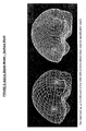
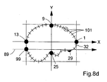
- Verfahren zum Erzeugen eines Gehirnformmodells, wobei das Verfahren die Schritte umfasst:Bereitstellen von Bildern einer Zahl von gesunden Referenzgehirnen;Durchführen einer statistischen Analyse der Bilder,beinhaltendNeuausrichten der Bilder in ein gemeinsames Koordinatensystem, unter Verwendung von mindestens zwei Merkpunkten entsprechend anatomischen Merkpunkten des Gehirns,dadurch gekennzeichnet, dassdie zwei Punkte dem vordersten Punkt des Frontallappens,und der Zerebellum-Temporallappen-Kerbe entsprechen.
- Verfahren nach Anspruch 1, wobei die Neuausrichtung von Gehirnbildern in ein gemeinsames Koordinatensystem die folgenden Schritte umfasst:für jedes Referenzgehirn, Bereitstellen eines Mittellinien-Sagittalschnitts;für den Mittellinien-Sagittalabschnitt, Finden undMarkieren der "Okzipital-Zerebullum-Kerbe;für den Mittellinlien-Sagittalschnitt, Finden undMarkieren des untersten Punkts des Frontallappens;Zeichnen einer Linie zwischen der Okzipital-Zerebullum-Kerbe und des untersten Punkts des Frontallappens;Ausrichten des Bildes, so dass die Linie horizontal wird, d.h. parallel zu der X-Achse;Finden des vordersten Punkts des Frontallappens;Positionieren des Bildes, so dass die X-Achse durch den vordersten Punkt des Frontallappens läuft;Finden der "Zerebullum-Temporallappen-Kerbe";Positionieren des Bildes, so dass die Y-Achse durch die Zerebullum-Temporallappen-Kerbe läuft;
Applications Claiming Priority (2)
| Application Number | Priority Date | Filing Date | Title |
|---|---|---|---|
| US74372806P | 2006-03-24 | 2006-03-24 | |
| PCT/EP2007/052890 WO2007110420A2 (en) | 2006-03-24 | 2007-03-26 | Automatic interpretation of 3-d medicine images of the brain and methods for producing intermediate results |
Publications (2)
| Publication Number | Publication Date |
|---|---|
| EP2005388A2 EP2005388A2 (de) | 2008-12-24 |
| EP2005388B1 true EP2005388B1 (de) | 2010-08-11 |
Family
ID=38093602
Family Applications (1)
| Application Number | Title | Priority Date | Filing Date |
|---|---|---|---|
| EP07727363A Active EP2005388B1 (de) | 2006-03-24 | 2007-03-26 | Automatische interpretation von medizinischen 3d-bildern des hirns und verfahren zum produzieren von zwischenergebnissen |
Country Status (5)
| Country | Link |
|---|---|
| US (1) | US8199985B2 (de) |
| EP (1) | EP2005388B1 (de) |
| AT (1) | ATE477557T1 (de) |
| DE (1) | DE602007008390D1 (de) |
| WO (1) | WO2007110420A2 (de) |
Families Citing this family (48)
| Publication number | Priority date | Publication date | Assignee | Title |
|---|---|---|---|---|
| US7983464B2 (en) * | 2006-08-08 | 2011-07-19 | Siemens Medical Solutions Usa, Inc. | System and method for corpus callosum segmentation in magnetic resonance images |
| JP5676269B2 (ja) * | 2007-12-14 | 2015-02-25 | コーニンクレッカ フィリップス エヌ ヴェ | 脳画像データの画像解析 |
| ATE522876T1 (de) * | 2008-01-31 | 2011-09-15 | Siemens Ag | Verfahren und system zur qualifizierung von cad- objekten |
| US9042629B2 (en) | 2008-05-14 | 2015-05-26 | Koninklijke Philips N.V. | Image classification based on image segmentation |
| WO2010117573A2 (en) * | 2009-04-07 | 2010-10-14 | Virginia Commonwealth University | Automated measurement of brain injury indices using brain ct images, injury data, and machine learning |
| US20110075724A1 (en) * | 2009-09-29 | 2011-03-31 | Qualcomm Incorporated | Encoding parameters with unit sum |
| WO2011163391A2 (en) * | 2010-06-22 | 2011-12-29 | The Johns Hopkins University | Atlas-based analysis for image-based anatomic and functional data of organism |
| WO2012058310A2 (en) * | 2010-10-26 | 2012-05-03 | The Johns Hopkins University | A computer-aided-detection (cad) system for personalized disease detection, assessment, and tracking, in medical imaging based on user selectable criteria |
| US20120253170A1 (en) * | 2011-03-29 | 2012-10-04 | Samsung Electronics Co., Ltd. | Method and apparatus for generating medical image of body organ by using 3-d model |
| BR112014006793B1 (pt) * | 2011-09-26 | 2021-09-28 | Koninklijke Philips N.V. | Sistema e método para habilitar uma inspeção interativa de uma região de interesse em uma imagem médica, estação de trabalho ou terminal e aparelho de formação de imagem |
| US20130136329A1 (en) * | 2011-11-30 | 2013-05-30 | General Electric Company | Method and system for automatically setting a landmark for brain scans |
| JP6214887B2 (ja) * | 2012-03-12 | 2017-10-18 | 東芝メディカルシステムズ株式会社 | レポート作成支援装置及びレポート閲覧装置 |
| US9218641B1 (en) * | 2012-06-19 | 2015-12-22 | Exelis, Inc. | Algorithm for calculating high accuracy image slopes |
| US9378587B2 (en) | 2012-06-27 | 2016-06-28 | Landmark Graphics Corporation | Systems and methods for creating a three-dimensional texture atlas |
| US9427211B2 (en) * | 2012-07-10 | 2016-08-30 | General Electric Company | Ultrasound imaging system and method |
| US9070090B2 (en) | 2012-08-28 | 2015-06-30 | Oracle International Corporation | Scalable string matching as a component for unsupervised learning in semantic meta-model development |
| US9201869B2 (en) | 2012-08-28 | 2015-12-01 | Oracle International Corporation | Contextually blind data conversion using indexed string matching |
| US9600778B2 (en) * | 2013-07-02 | 2017-03-21 | Surgical Information Sciences, Inc. | Method for a brain region location and shape prediction |
| KR102273831B1 (ko) * | 2014-01-07 | 2021-07-07 | 삼성메디슨 주식회사 | 의료 영상을 디스플레이 하는 방법 및 그 의료 영상 장치 |
| GB201403772D0 (en) * | 2014-03-04 | 2014-04-16 | Ucl Business Plc | Apparatus and method for generating and using a subject-specific statistical motion model |
| EP3277178B1 (de) * | 2015-03-31 | 2020-03-11 | Cortechs Labs, Inc. | Atlas für kovariaten-modulation |
| US10360675B2 (en) | 2015-06-12 | 2019-07-23 | International Business Machines Corporation | Methods and systems for automatically analyzing clinical images using rules and image analytics |
| US10082551B2 (en) * | 2015-10-19 | 2018-09-25 | Ecole Polytechnique Federale De Lausanne (Epfl) | Learning-based subsampling |
| CN105761304B (zh) * | 2016-02-02 | 2018-07-20 | 飞依诺科技(苏州)有限公司 | 三维脏器模型构造方法和装置 |
| ES3041039T3 (en) | 2016-10-27 | 2025-11-06 | Progenics Pharm Inc | Network for medical image analysis, decision support system, and related graphical user interface (gui) applications |
| US10482128B2 (en) | 2017-05-15 | 2019-11-19 | Oracle International Corporation | Scalable approach to information-theoretic string similarity using a guaranteed rank threshold |
| US11723579B2 (en) | 2017-09-19 | 2023-08-15 | Neuroenhancement Lab, LLC | Method and apparatus for neuroenhancement |
| US10885056B2 (en) | 2017-09-29 | 2021-01-05 | Oracle International Corporation | Data standardization techniques |
| US11717686B2 (en) | 2017-12-04 | 2023-08-08 | Neuroenhancement Lab, LLC | Method and apparatus for neuroenhancement to facilitate learning and performance |
| US10832808B2 (en) | 2017-12-13 | 2020-11-10 | International Business Machines Corporation | Automated selection, arrangement, and processing of key images |
| US12280219B2 (en) | 2017-12-31 | 2025-04-22 | NeuroLight, Inc. | Method and apparatus for neuroenhancement to enhance emotional response |
| US11273283B2 (en) | 2017-12-31 | 2022-03-15 | Neuroenhancement Lab, LLC | Method and apparatus for neuroenhancement to enhance emotional response |
| US11364361B2 (en) | 2018-04-20 | 2022-06-21 | Neuroenhancement Lab, LLC | System and method for inducing sleep by transplanting mental states |
| WO2020056418A1 (en) | 2018-09-14 | 2020-03-19 | Neuroenhancement Lab, LLC | System and method of improving sleep |
| US11665372B2 (en) * | 2019-01-07 | 2023-05-30 | Samsung Electronics Co., Ltd. | Fast projection method in video-based point cloud compression codecs |
| AU2020206584B2 (en) | 2019-01-07 | 2024-11-07 | Exini Diagnostics Ab | Systems and methods for platform agnostic whole body image segmentation |
| KR102204371B1 (ko) * | 2019-03-25 | 2021-01-19 | 세종대학교산학협력단 | 다중시기 측부혈류 영상을 생성하기 위한 학습 방법 및 기계 학습을 이용한 다중시기 측부혈류 영상 생성 방법 |
| JP7539921B2 (ja) | 2019-04-24 | 2024-08-26 | プロジェニクス ファーマシューティカルズ, インコーポレイテッド | 核医学画像における強度ウィンドウ処理の双方向調節のためのシステムおよび方法 |
| TWI872062B (zh) | 2019-04-24 | 2025-02-11 | 美商普吉尼製藥公司 | 用於偵測轉移之骨掃描影像之自動及互動式分析系統、裝置及方法 |
| CN110400313B (zh) * | 2019-08-01 | 2021-01-01 | 北京灵医灵科技有限公司 | 一种核磁共振影像的软组织分离方法和分离系统 |
| US11564621B2 (en) | 2019-09-27 | 2023-01-31 | Progenies Pharmacenticals, Inc. | Systems and methods for artificial intelligence-based image analysis for cancer assessment |
| US11900597B2 (en) | 2019-09-27 | 2024-02-13 | Progenics Pharmaceuticals, Inc. | Systems and methods for artificial intelligence-based image analysis for cancer assessment |
| US12417533B2 (en) | 2019-09-27 | 2025-09-16 | Progenics Pharmaceuticals, Inc. | Systems and methods for artificial intelligence-based image analysis for cancer assessment |
| US11544407B1 (en) | 2019-09-27 | 2023-01-03 | Progenics Pharmaceuticals, Inc. | Systems and methods for secure cloud-based medical image upload and processing |
| CN111242169B (zh) * | 2019-12-31 | 2024-03-26 | 浙江工业大学 | 一种基于图片相似度计算的脑纤维视角自动选择方法 |
| US11321844B2 (en) | 2020-04-23 | 2022-05-03 | Exini Diagnostics Ab | Systems and methods for deep-learning-based segmentation of composite images |
| US11386988B2 (en) | 2020-04-23 | 2022-07-12 | Exini Diagnostics Ab | Systems and methods for deep-learning-based segmentation of composite images |
| US11721428B2 (en) | 2020-07-06 | 2023-08-08 | Exini Diagnostics Ab | Systems and methods for artificial intelligence-based image analysis for detection and characterization of lesions |
Family Cites Families (7)
| Publication number | Priority date | Publication date | Assignee | Title |
|---|---|---|---|---|
| US6195409B1 (en) * | 1998-05-22 | 2001-02-27 | Harbor-Ucla Research And Education Institute | Automatic scan prescription for tomographic imaging |
| US6366797B1 (en) * | 1998-08-25 | 2002-04-02 | The Cleveland Clinic Foundation | Method and system for brain volume analysis |
| US6430430B1 (en) * | 1999-04-29 | 2002-08-06 | University Of South Florida | Method and system for knowledge guided hyperintensity detection and volumetric measurement |
| SE524500C2 (sv) | 2002-09-16 | 2004-08-17 | Weaidu In Europ Ab | Förfarande och anordning för bestämning av en tredimensionell kontur av ett organ i en patients kropp |
| US7450983B2 (en) * | 2003-03-18 | 2008-11-11 | University Of Cincinnati | Automated brain MRI and CT prescriptions in Talairach space |
| JP4537681B2 (ja) * | 2003-09-24 | 2010-09-01 | 株式会社東芝 | 血流解析装置 |
| US20100049035A1 (en) * | 2005-05-27 | 2010-02-25 | Qingmao Hu | Brain image segmentation from ct data |
-
2007
- 2007-03-26 EP EP07727363A patent/EP2005388B1/de active Active
- 2007-03-26 AT AT07727363T patent/ATE477557T1/de not_active IP Right Cessation
- 2007-03-26 US US12/294,112 patent/US8199985B2/en active Active
- 2007-03-26 DE DE602007008390T patent/DE602007008390D1/de active Active
- 2007-03-26 WO PCT/EP2007/052890 patent/WO2007110420A2/en not_active Ceased
Also Published As
| Publication number | Publication date |
|---|---|
| US8199985B2 (en) | 2012-06-12 |
| DE602007008390D1 (de) | 2010-09-23 |
| WO2007110420A3 (en) | 2007-12-27 |
| EP2005388A2 (de) | 2008-12-24 |
| WO2007110420A2 (en) | 2007-10-04 |
| ATE477557T1 (de) | 2010-08-15 |
| US20100067761A1 (en) | 2010-03-18 |
Similar Documents
| Publication | Publication Date | Title |
|---|---|---|
| EP2005388B1 (de) | Automatische interpretation von medizinischen 3d-bildern des hirns und verfahren zum produzieren von zwischenergebnissen | |
| AlZu’bi et al. | Parallel implementation for 3d medical volume fuzzy segmentation | |
| Declerck et al. | Automatic registration and alignment on a template of cardiac stress and rest reoriented SPECT images | |
| Kumar et al. | Automatic liver and lesion segmentation: a primary step in diagnosis of liver diseases | |
| EP2297698A1 (de) | Verfahren und system zur läsionssegmentierung | |
| CN114282588B (zh) | 提供分类解释和生成函数 | |
| Lohmann | Extracting line representations of sulcal and gyral patterns in MR images of the human brain | |
| Saad et al. | Exploration and visualization of segmentation uncertainty using shape and appearance prior information | |
| AU2018350632B2 (en) | Method and apparatus for imaging an organ | |
| Tan et al. | An approach to extraction midsagittal plane of skull from brain CT images for oral and maxillofacial surgery | |
| Slomka et al. | Automated three-dimensional quantification of myocardial perfusion and brain SPECT | |
| Shattuck et al. | Brainsuite: An automated cortical surface identification tool | |
| Kim et al. | Segmentation of VOI from multidimensional dynamic PET images by integrating spatial and temporal features | |
| CN110728685B (zh) | 一种基于对角体素的局部二值模式纹理算子的脑组织分割方法 | |
| Roy et al. | Automated medical image segmentation: a survey | |
| Ge et al. | Accurate localization of cortical convolutions in MR brain images | |
| CN120147346A (zh) | 基于深度学习的脑血管影像识别分析系统 | |
| Abdolali et al. | Mandibular canal segmentation using 3D Active Appearance Models and shape context registration | |
| KR100680232B1 (ko) | 뇌질환의 진단보조를 위한 뇌 해마 분석 방법 및 그 방법이수록되어 컴퓨터로 읽을 수 있는 기록매체 | |
| Nouranian et al. | An automatic multi-atlas segmentation of the prostate in transrectal ultrasound images using pairwise atlas shape similarity | |
| CN115690207B (zh) | 一种基于头部临床影像的自动定位方法及装置 | |
| Grigorios-Aris et al. | Automatic segmentation of lungs in SPECT images using active shape model trained by meshes delineated in CT images | |
| Erdt et al. | Computer aided segmentation of kidneys using locally shape constrained deformable models on CT images | |
| US20240341701A1 (en) | Brain amyloid pet processing system and operation method thereof and non-transitory computer readable medium | |
| Trivedi | Identification of Lung Nodule Using Hierarchical Graph-Based Clustering and Multi-Level Thresholding |
Legal Events
| Date | Code | Title | Description |
|---|---|---|---|
| PUAI | Public reference made under article 153(3) epc to a published international application that has entered the european phase |
Free format text: ORIGINAL CODE: 0009012 |
|
| 17P | Request for examination filed |
Effective date: 20081024 |
|
| AK | Designated contracting states |
Kind code of ref document: A2 Designated state(s): AT BE BG CH CY CZ DE DK EE ES FI FR GB GR HU IE IS IT LI LT LU LV MC MT NL PL PT RO SE SI SK TR |
|
| RIN1 | Information on inventor provided before grant (corrected) |
Inventor name: RICHTER, JENS Inventor name: JAKOBSSON, DAVID Inventor name: JAERUND, ANDREAS |
|
| 17Q | First examination report despatched |
Effective date: 20090225 |
|
| GRAP | Despatch of communication of intention to grant a patent |
Free format text: ORIGINAL CODE: EPIDOSNIGR1 |
|
| DAX | Request for extension of the european patent (deleted) | ||
| GRAS | Grant fee paid |
Free format text: ORIGINAL CODE: EPIDOSNIGR3 |
|
| GRAA | (expected) grant |
Free format text: ORIGINAL CODE: 0009210 |
|
| AK | Designated contracting states |
Kind code of ref document: B1 Designated state(s): AT BE BG CH CY CZ DE DK EE ES FI FR GB GR HU IE IS IT LI LT LU LV MC MT NL PL PT RO SE SI SK TR |
|
| REG | Reference to a national code |
Ref country code: GB Ref legal event code: FG4D |
|
| REG | Reference to a national code |
Ref country code: CH Ref legal event code: EP |
|
| REG | Reference to a national code |
Ref country code: IE Ref legal event code: FG4D |
|
| REF | Corresponds to: |
Ref document number: 602007008390 Country of ref document: DE Date of ref document: 20100923 Kind code of ref document: P |
|
| REG | Reference to a national code |
Ref country code: NL Ref legal event code: VDEP Effective date: 20100811 |
|
| LTIE | Lt: invalidation of european patent or patent extension |
Effective date: 20100811 |
|
| PG25 | Lapsed in a contracting state [announced via postgrant information from national office to epo] |
Ref country code: LT Free format text: LAPSE BECAUSE OF FAILURE TO SUBMIT A TRANSLATION OF THE DESCRIPTION OR TO PAY THE FEE WITHIN THE PRESCRIBED TIME-LIMIT Effective date: 20100811 Ref country code: AT Free format text: LAPSE BECAUSE OF FAILURE TO SUBMIT A TRANSLATION OF THE DESCRIPTION OR TO PAY THE FEE WITHIN THE PRESCRIBED TIME-LIMIT Effective date: 20100811 Ref country code: FI Free format text: LAPSE BECAUSE OF FAILURE TO SUBMIT A TRANSLATION OF THE DESCRIPTION OR TO PAY THE FEE WITHIN THE PRESCRIBED TIME-LIMIT Effective date: 20100811 Ref country code: NL Free format text: LAPSE BECAUSE OF FAILURE TO SUBMIT A TRANSLATION OF THE DESCRIPTION OR TO PAY THE FEE WITHIN THE PRESCRIBED TIME-LIMIT Effective date: 20100811 |
|
| PG25 | Lapsed in a contracting state [announced via postgrant information from national office to epo] |
Ref country code: CY Free format text: LAPSE BECAUSE OF FAILURE TO SUBMIT A TRANSLATION OF THE DESCRIPTION OR TO PAY THE FEE WITHIN THE PRESCRIBED TIME-LIMIT Effective date: 20100811 Ref country code: PL Free format text: LAPSE BECAUSE OF FAILURE TO SUBMIT A TRANSLATION OF THE DESCRIPTION OR TO PAY THE FEE WITHIN THE PRESCRIBED TIME-LIMIT Effective date: 20100811 Ref country code: IS Free format text: LAPSE BECAUSE OF FAILURE TO SUBMIT A TRANSLATION OF THE DESCRIPTION OR TO PAY THE FEE WITHIN THE PRESCRIBED TIME-LIMIT Effective date: 20101211 Ref country code: PT Free format text: LAPSE BECAUSE OF FAILURE TO SUBMIT A TRANSLATION OF THE DESCRIPTION OR TO PAY THE FEE WITHIN THE PRESCRIBED TIME-LIMIT Effective date: 20101213 Ref country code: SI Free format text: LAPSE BECAUSE OF FAILURE TO SUBMIT A TRANSLATION OF THE DESCRIPTION OR TO PAY THE FEE WITHIN THE PRESCRIBED TIME-LIMIT Effective date: 20100811 Ref country code: BG Free format text: LAPSE BECAUSE OF FAILURE TO SUBMIT A TRANSLATION OF THE DESCRIPTION OR TO PAY THE FEE WITHIN THE PRESCRIBED TIME-LIMIT Effective date: 20101111 |
|
| PG25 | Lapsed in a contracting state [announced via postgrant information from national office to epo] |
Ref country code: GR Free format text: LAPSE BECAUSE OF FAILURE TO SUBMIT A TRANSLATION OF THE DESCRIPTION OR TO PAY THE FEE WITHIN THE PRESCRIBED TIME-LIMIT Effective date: 20101112 Ref country code: SE Free format text: LAPSE BECAUSE OF FAILURE TO SUBMIT A TRANSLATION OF THE DESCRIPTION OR TO PAY THE FEE WITHIN THE PRESCRIBED TIME-LIMIT Effective date: 20100811 Ref country code: BE Free format text: LAPSE BECAUSE OF FAILURE TO SUBMIT A TRANSLATION OF THE DESCRIPTION OR TO PAY THE FEE WITHIN THE PRESCRIBED TIME-LIMIT Effective date: 20100811 Ref country code: LV Free format text: LAPSE BECAUSE OF FAILURE TO SUBMIT A TRANSLATION OF THE DESCRIPTION OR TO PAY THE FEE WITHIN THE PRESCRIBED TIME-LIMIT Effective date: 20100811 |
|
| PG25 | Lapsed in a contracting state [announced via postgrant information from national office to epo] |
Ref country code: DK Free format text: LAPSE BECAUSE OF FAILURE TO SUBMIT A TRANSLATION OF THE DESCRIPTION OR TO PAY THE FEE WITHIN THE PRESCRIBED TIME-LIMIT Effective date: 20100811 |
|
| PG25 | Lapsed in a contracting state [announced via postgrant information from national office to epo] |
Ref country code: RO Free format text: LAPSE BECAUSE OF FAILURE TO SUBMIT A TRANSLATION OF THE DESCRIPTION OR TO PAY THE FEE WITHIN THE PRESCRIBED TIME-LIMIT Effective date: 20100811 Ref country code: EE Free format text: LAPSE BECAUSE OF FAILURE TO SUBMIT A TRANSLATION OF THE DESCRIPTION OR TO PAY THE FEE WITHIN THE PRESCRIBED TIME-LIMIT Effective date: 20100811 Ref country code: IT Free format text: LAPSE BECAUSE OF FAILURE TO SUBMIT A TRANSLATION OF THE DESCRIPTION OR TO PAY THE FEE WITHIN THE PRESCRIBED TIME-LIMIT Effective date: 20100811 Ref country code: CZ Free format text: LAPSE BECAUSE OF FAILURE TO SUBMIT A TRANSLATION OF THE DESCRIPTION OR TO PAY THE FEE WITHIN THE PRESCRIBED TIME-LIMIT Effective date: 20100811 Ref country code: SK Free format text: LAPSE BECAUSE OF FAILURE TO SUBMIT A TRANSLATION OF THE DESCRIPTION OR TO PAY THE FEE WITHIN THE PRESCRIBED TIME-LIMIT Effective date: 20100811 |
|
| PLBE | No opposition filed within time limit |
Free format text: ORIGINAL CODE: 0009261 |
|
| STAA | Information on the status of an ep patent application or granted ep patent |
Free format text: STATUS: NO OPPOSITION FILED WITHIN TIME LIMIT |
|
| PG25 | Lapsed in a contracting state [announced via postgrant information from national office to epo] |
Ref country code: ES Free format text: LAPSE BECAUSE OF FAILURE TO SUBMIT A TRANSLATION OF THE DESCRIPTION OR TO PAY THE FEE WITHIN THE PRESCRIBED TIME-LIMIT Effective date: 20101122 |
|
| 26N | No opposition filed |
Effective date: 20110512 |
|
| REG | Reference to a national code |
Ref country code: DE Ref legal event code: R097 Ref document number: 602007008390 Country of ref document: DE Effective date: 20110512 |
|
| PG25 | Lapsed in a contracting state [announced via postgrant information from national office to epo] |
Ref country code: MC Free format text: LAPSE BECAUSE OF NON-PAYMENT OF DUE FEES Effective date: 20110331 |
|
| REG | Reference to a national code |
Ref country code: CH Ref legal event code: PL |
|
| PG25 | Lapsed in a contracting state [announced via postgrant information from national office to epo] |
Ref country code: MT Free format text: LAPSE BECAUSE OF FAILURE TO SUBMIT A TRANSLATION OF THE DESCRIPTION OR TO PAY THE FEE WITHIN THE PRESCRIBED TIME-LIMIT Effective date: 20100811 |
|
| REG | Reference to a national code |
Ref country code: IE Ref legal event code: MM4A |
|
| PG25 | Lapsed in a contracting state [announced via postgrant information from national office to epo] |
Ref country code: LI Free format text: LAPSE BECAUSE OF NON-PAYMENT OF DUE FEES Effective date: 20110331 Ref country code: IE Free format text: LAPSE BECAUSE OF NON-PAYMENT OF DUE FEES Effective date: 20110326 Ref country code: CH Free format text: LAPSE BECAUSE OF NON-PAYMENT OF DUE FEES Effective date: 20110331 |
|
| PG25 | Lapsed in a contracting state [announced via postgrant information from national office to epo] |
Ref country code: LU Free format text: LAPSE BECAUSE OF NON-PAYMENT OF DUE FEES Effective date: 20110326 |
|
| PG25 | Lapsed in a contracting state [announced via postgrant information from national office to epo] |
Ref country code: TR Free format text: LAPSE BECAUSE OF FAILURE TO SUBMIT A TRANSLATION OF THE DESCRIPTION OR TO PAY THE FEE WITHIN THE PRESCRIBED TIME-LIMIT Effective date: 20100811 |
|
| PG25 | Lapsed in a contracting state [announced via postgrant information from national office to epo] |
Ref country code: HU Free format text: LAPSE BECAUSE OF FAILURE TO SUBMIT A TRANSLATION OF THE DESCRIPTION OR TO PAY THE FEE WITHIN THE PRESCRIBED TIME-LIMIT Effective date: 20100811 |
|
| REG | Reference to a national code |
Ref country code: FR Ref legal event code: PLFP Year of fee payment: 10 |
|
| REG | Reference to a national code |
Ref country code: FR Ref legal event code: PLFP Year of fee payment: 11 |
|
| REG | Reference to a national code |
Ref country code: FR Ref legal event code: PLFP Year of fee payment: 12 |
|
| P01 | Opt-out of the competence of the unified patent court (upc) registered |
Effective date: 20230512 |
|
| PGFP | Annual fee paid to national office [announced via postgrant information from national office to epo] |
Ref country code: DE Payment date: 20250319 Year of fee payment: 19 |
|
| PGFP | Annual fee paid to national office [announced via postgrant information from national office to epo] |
Ref country code: FR Payment date: 20250325 Year of fee payment: 19 |
|
| PGFP | Annual fee paid to national office [announced via postgrant information from national office to epo] |
Ref country code: GB Payment date: 20250319 Year of fee payment: 19 |