EP2005221B1 - Verfahren und vorrichtung zur messung einer bohrlocheigenschaft - Google Patents
Verfahren und vorrichtung zur messung einer bohrlocheigenschaft Download PDFInfo
- Publication number
- EP2005221B1 EP2005221B1 EP07758461.3A EP07758461A EP2005221B1 EP 2005221 B1 EP2005221 B1 EP 2005221B1 EP 07758461 A EP07758461 A EP 07758461A EP 2005221 B1 EP2005221 B1 EP 2005221B1
- Authority
- EP
- European Patent Office
- Prior art keywords
- borehole
- conductive pipe
- inlet
- characteristic
- network device
- Prior art date
- Legal status (The legal status is an assumption and is not a legal conclusion. Google has not performed a legal analysis and makes no representation as to the accuracy of the status listed.)
- Not-in-force
Links
Images


Classifications
-
- E—FIXED CONSTRUCTIONS
- E21—EARTH OR ROCK DRILLING; MINING
- E21B—EARTH OR ROCK DRILLING; OBTAINING OIL, GAS, WATER, SOLUBLE OR MELTABLE MATERIALS OR A SLURRY OF MINERALS FROM WELLS
- E21B47/00—Survey of boreholes or wells
- E21B47/06—Measuring temperature or pressure
-
- E—FIXED CONSTRUCTIONS
- E21—EARTH OR ROCK DRILLING; MINING
- E21B—EARTH OR ROCK DRILLING; OBTAINING OIL, GAS, WATER, SOLUBLE OR MELTABLE MATERIALS OR A SLURRY OF MINERALS FROM WELLS
- E21B17/00—Drilling rods or pipes; Flexible drill strings; Kellies; Drill collars; Sucker rods; Cables; Casings; Tubings
- E21B17/02—Couplings; joints
- E21B17/028—Electrical or electro-magnetic connections
- E21B17/0283—Electrical or electro-magnetic connections characterised by the coupling being contactless, e.g. inductive
Definitions
- An apparatus and method are disclosed for sensing a characteristic of a borehole.
- U.S. Pat. No. 6,766,141 (Briles et al ) discloses a system for remote down-hole well telemetry.
- the telemetry communication is used for oil well monitoring and recording instruments located in a vicinity of a bottom of a gas or oil recovery pipe. Modulated reflectance is described for monitoring down-hole conditions.
- a radio frequency (RF) generator/receiver base station communicates electrically with the pipe.
- the RF frequency is described as an electromagnetic radiation between 3 Hz and 30 GHz.
- a down-hole electronics module having a reflecting antenna receives a radiated carrier signal from the RF generator/receiver.
- An antenna on the electronics module can have a parabolic or other focusing shape.
- the radiated carrier signal is then reflected in a modulated manner, the modulation being responsive to measurements performed by the electronics module.
- the reflected, modulated signal is transmitted by the pipe to the surface of the well where it can be detected by the RF generator/receiver.
- An exemplary apparatus includes a conductive pipe; an inlet coupled (e.g., connected) to the conductive pipe, for applying an electric pulse to the conductive pipe; a resonant network device (such as a resonant cavity) connected with the conductive pipe; and a transducer which is in operative communication with the resonant network device to measure a borehole characteristic, the transducer being configured to affect a modulation of a resonator vibration frequency induced in the resonant network device when a pulse is applied to the inlet; and wherein the inlet further includes: a probe coupled with the conductive pipe; and an inductor for electrically isolating the inlet from a common ground potential at a location in a vicinity of the inlet, wherein the resonant network device comprises a magnetically coupled resonating network.
- An exemplary method includes transmitting an electric pulse along a conductive pipe located within the borehole, wherein transmitting the pulse comprises transmitting the pulse to an inlet coupled to the conductive pipe; providing a transducer in operative communication with a resonant network device, the transducer being configured to affect a modulation of a resonator vibration frequency induced in the resonant network device within a hollow borehole casing when a pulse is applied to the inlet; and sensing the modulated vibration frequency, as a measure of the borehole characteristic; wherein the inlet further includes: a probe coupled with the conductive pipe; and an inductor for electrically isolating the inlet from a common ground potential at a location in a vicinity of the inlet, wherein the resonant network device comprises a magnetically coupled resonating network.
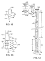
- Figure 1 shows an exemplary apparatus 100 for sensing a characteristic of a borehole.
- the borehole can be any cavity, configured with any orientation, having a characteristic such as a material composition, temperature, pressure, flow rate, or other characteristic, which can vary along a length of the borehole.
- the apparatus 100 includes a means, such as a conductive pipe 102, for conducting a pulse through the borehole.
- An inlet 104 coupled (e.g., connected) to the conductive pipe 102, is provided for applying a pulse to the conductive pipe.
- the pulse can be an electrical transient pulse or any desired electrical pulse of any desired frequency selected, for example, as a function of characteristics to be measured within the borehole and as a function of the length and size of the borehole.
- the inlet includes a probe 106 coupled with the conductive pipe 102.
- the probe can be formed, for example, as a coaxial connector having a first (e.g., interior) conductor coupled electrically to the conductive pipe 102, and having a second (e.g., exterior) conductive casing coupled to a hollow borehole casing 111.
- An insulator is used to separate the interior conductor from the exterior conductive casing.
- the inlet includes an inductive isolator, such as a ferrite inductance 108 or other inductor or component, for electrically isolating the inlet from a first common ground potential at a location in a vicinity of the inlet 104.
- the apparatus 100 can include a means, such as a pulse generator 105, coupled to the inlet for generating the pulse to be applied to the conductive pipe.
- the hollow borehole casing 111 can be placed into the borehole whose characteristics are to be monitored.
- the hollow borehole casing 111 can, for example, be configured of steel or other suitable material.
- the conductive pipe 102 can be located within, and electrically isolated from, the hollow borehole casing using spacers 116.
- the spacers can, for example, be configured as insulated centralizers which maintain a separation distance of the conductive pipe 102 from the inner walls of the hollow borehole casing 111.
- These insulating spacers can be configured as disks formed from any suitable material including, but not limited to nylon.
- the apparatus 100 includes a resonant network device 110 responsive to the pulse, for resonating at a frequency which is modulated as a function of a characteristic of the borehole.
- the resonant network device 110 comprises a magnetically coupled electrically resonant mechanical structure for performing an electrical resonance, such as the resonant cavity of Figure 2A , the tank circuit of Figure 2A , or any other suitable device.
- the resonant network device can be connected with or mechanically coupled to the conductive pipe.
- a torroidal core of the resonant network device can be magnetically coupled to the conductive pipe.
- the torroidal core is a magnetic core formed as a medium by which a magnetic field can be contained and/or enhanced. For example, a single turn coil with a one inch cross-section wrapped around a ferrite core, or any other suitable device of any suitable shape, size and configuration can be used.
- a magnetic core is a material significantly affected by a magnetic field in its region, due to the orientable dipoles within its molecular structure. Such a material can confine and/or intensify an applied magnetic field due to its low magnetic reluctance.
- the wellhead Ferrite isolator can provide a compact inductive impedance in a range of, for example, 90-110 ohms reactive between an inlet feed point on the pipe and a wellhead flange short.
- This impedance, in parallel with an exemplary 47 ohm characteristic impedance of the pipe-casing transmission line can reduce the transmitted and received signals by, for example, about ⁇ 3dbV at the inlet feed point for a typical band center at 50 MHz.
- the magnetic permeability of the ferrite cores discussed herein can range from ⁇ 20 to slightly over 100, or lesser or greater. As such, for a given inductance of an air-core inductor, when the core material is inserted, the natural inductance can be multiplied by about these same factors. Selected core materials can be used for the frequency range of, for example, 10-100 MHz, or lesser or greater.
- the resonant network device 110 illustrated in Figure 1 will be described as the resonant cavity, of Figure 2A .
- the tank core of Figure 2B can be readily substituted, as can any other suitable resonant network device known to those skilled in the art.
- the resonant cavity is electrically connected to the conductive pipe, and is located within the hollow borehole casing 111.
- a length "b" of the resonant cavity within the hollow borehole casing is defined by an inductive isolator formed, for example, as a torroidal core 112 at a first end of the resonant cavity, and by a connection 114 at a first potential (e.g., common ground) at a second end of the resonant cavity.
- the resonant network device 110 receives energy from the pulse, and "rings" at its natural frequency.
- a means for sensing includes a transducer provided in operative communication with the resonant network device 110, and magnetically coupled with the first (e.g., common ground) potential.
- the transducer is configured to sense a characteristic associated with the borehole, and to modulate the vibration frequency induced in the resonant network device 111 when a pulse is applied to the inlet 104.
- the modulated vibration frequency can be processed to provide a measure of the borehole characteristic. That is, the vibration frequency induced by the pulse is modulated by a sensed characteristic of the borehole, and this modulation of the vibration can be processed to provide a measure of the characteristic.
- a sensing means can include, or be associated with, means for processing, represented as a processor (e.g., computer 118).
- the processor means can process an output of the resonant network device as transmitted via the borehole casing 111.
- the processor 118 can provide a signal representing the characteristic to be measured or monitored.
- the processor 118 can be programmed to produce a process the modulated vibration frequency to provide a measure of the sensed characteristic.
- the measure which can, for example, be displayed to a user via a general user interface (GUI) 120.
- the processor 118 can perform any desired processing of the detected signal including, but not limited to, a statistical (e.g., Fourier) analysis of the modulated vibration frequency.
- a statistical (e.g., Fourier) analysis of the modulated vibration frequency Commercial products are readily available and known to those skilled in the art can be to perform any suitable frequency detection (such as a fast Fourier transform that can be implemented by, for example, MATHCAD available from Mathsoft Engineering & Education, Inc. or other suitable product to deconvolve the modulated ring received from the resonant network device.
- the processor can be used in conjunction with a look-up table having a correlation table of modulation frequency-to sensed characteristics (e.g., temperature, pressure, and so forth) conversions.
- the hollow borehole casing 111 is at the first potential (e.g., common ground).
- the hollow borehole casing can be at a common ground potential at both a location in a vicinity of the inlet 104, and at a location in a vicinity of the resonant network device 110.
- the grounding of the hollow borehole casing in a vicinity of the inlet establishes a known impedance for the conductive pipe.
- the grounding of the hollow borehole casing in a vicinity of the resonant network device (that is, at a lower end of the resonant cavity as depicted in Figure 1A ) allows the resonant length to be defined. That is, the resonant cavity has a length within the hollow borehole casing defined by the distance between torroidal coil 112 and by the ground connection at a second, lower end of the resonant cavity.
- the transducer can be configured to include passive electrical components, such as inductors and/or capacitors, such that no down-hole power is needed.
- the conductive pipe can be assembled in sections, and a spacer can be included at each joint between the various pipe sections to ensure stability.
- a transducer used for sensing the modulated vibration frequency can be calibrated using the GUI 120 and processor 118.
- Figure 1 A Details of the exemplary Figure 1A apparatus will be described further with respect to Figure 1 B , which shows an exemplary telemetry component of the exemplary Figure 1 apparatus.
- the wavelength of the resonant "ring" frequency can dictate the size (e.g., length) of the device.
- the size constraint can be influenced (e.g., reduced) by "loading" the device with inductance and/or capacitance.
- the amount of ferrite used in an exemplary embodiment can be selected as a function of desired frequency and size considerations.
- An instrumentation signal port 112 is provided for receiving the probe 106.
- a wellhead configuration as depicted in Figure 1B , is short circuited to the hollow borehole casing.
- the ferrite inductor 108 thus isolates the conductive probe of the inlet, which is coupled with the conductive pipe 102, from the top of the wellhead which, in an exemplary embodiment, is at the common ground potential.
- the ferrite inductor isolates the short circuited wellhead flange from the conductive pipe used to convey a pulse from the probe to the resonant cavity.
- An exemplary impedance 126 between the conductive pipe and the hollow borehole casing 111 can be on the order of 47 ohms, or lesser or greater.
- This portion of the conductive pipe serves as a transmission line for communication of the down-hole electronics, such as the transducer, with the surface electronics, such as the processor.
- Figure1C illustrates an electrical representation of the resonant cavity and transducer included therein.
- the torroidal core 112 is represented as an inductor section configured of ferrite material for connecting the conductive pipe 102 with the resonant cavity 110.
- an upper portion 132 of the resonant cavity 110 coincides with a lower section of the torroidal core 112 and can be at an impedance which, in an exemplary embodiment, is relatively high as compared to the impedance between conductive pipe 102 and the casing 111.
- the impedance at the top of the resonant cavity can be on the order of 2000 ohms, or lesser or greater.
- those measures may have little or no relevance.
- This relatively large differential impedance at the top of the resonant cavity relative to the conductive pipe above the resonant cavity provides, at least in part, an ability of the cavity to resonate, or "ring" in response to the pulse and thereby provide a high degree of sensitivity in measuring a characteristic of interest.
- the ability of the transducer to provide a relatively high degree of sensitivity is aided by placing a lower end of the resonant cavity at the common ground potential.
- the Figure 1C electrical representation of the resonant network device for a coaxial cavity formed by the conductive pipe and the borehole casing, includes a representation of the resonant network resistance 128 and the resonant network inductance 130.
- a lower portion of the cavity defined by the common ground connection 114 is illustrated in Figure 1C , such that the cavity is defined by the bottom of the torroidal core 112 and the ground connection 114.
- a capacitance of the sleeve associated with the resonant cavity is represented as a sleeve capacitance 134.
- the transducer associated with the resonant cavity for modulating the vibration frequency induced by the pulse, as acted upon by the characteristic to be measured, is represented as a transducer 136.
- the bottom of the resonant capacity can include a Packer seal, to prevent the conductive pipe 102 from touching the hollow borehole casing 111.
- the Packer 138 as illustrated in Figure 1C and in Figure 1A , includes exposed conductors 140 which can interface with conductive portions of the resonant cavity and the hollow borehole casing 111 to achieve the common ground connection 114 at a lower end of the resonant cavity.
- Figure 1D illustrates another detail of the well telemetry component included at an upper end of the conductive pipe 102.
- a connection of the probe 106 to the conductive pipe 102 is illustrated as passing through the hollow borehole casing 111, in the inlet 104, Figure 1D shows that the probe 106 is isolated from the short circuited wellhead flange 124 via the ferrite inductor 108.
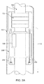
- FIG 2A shows an exemplary detail of a resonant network device 110 formed as a resonant cavity.
- the hollow borehole casing 111 can be seen to house the conductive pipe 102.
- the torroidal core 112 is illustrated, a bottom of which, in the direction going downward into the borehole, constitutes an upper end of the resonant cavity.
- the transducer 136 is illustrated as being located within a portion of the resonant cavity, and is associated with a conductive sensor sleeve 202, the capacitance of which is represented in Figure 1C as the sleeve capacitance 134.
- the ferrite torroidal core 112 can be configured as torroidal core slipped into a plastic end piece. Such ferrite materials are readily available, such as cores available from Fair-Rite Incorporated, configured as a low ⁇ , radio frequency type material, or any other suitable material. Mounting screws 204 are illustrated, and can be used to maintain the sensor sleeve and transducer in place at a location along a length of the conductive pipe 102. A bottom of the resonant cavity, which coincides with a common ground connection of the Packer to the hollow borehole casing, is not shown in Figure 2 .
- FIG. 2B illustrates an exemplary detail of a resonant network 110 formed as a tank circuit.
- multiple resonant network devices 206 associated with multiple sensor packages can be included at or near the Packer.
- resonators using capacitive sensors and ferrite coupling transformers are provided. Again, the hollow borehole 111 can be seen to house the conductive pipe 102.
- Each resonant network device is configured as a torroidal core 208 having an associated coil resonator 210. No significant impedance matching, or pipe-casing shorting modifications, to an existing well string need be implemented.
- the coaxial string structure can carry direct to a short at the Packer using the ferrite torroid resonators as illustrated in Figure 2B , without a matching section as with the resonant cavity configuration.
- the conductive pipe can be effectively represented as a single turn winding 214 in the transformer construct, and several secondary windings 216 can be stacked on the single primary current path.
- the quality of the Packer short is of little or no significance.
- Metal-toothed Packers can alternatively be used.
- the return signal using this transformer method can be detected, in exemplary embodiments without using a low Packer shorting impedance.
- spacing between multiple resonant network devices 206 can be selected as a function of the desired application.
- the resonant network devices 206 should be separated sufficiently to mitigate or eliminate mechanical constraints. In addition, separation should be selected to mitigate or eliminate coupling between them.
- one width of a ring can decrease coupling for typical applications.
- the inductance and/or capacitance of each resonance network device can be modified by adding coil turns, and the number of turns can be selected as a function of the application. For example, the number of turns will seta ring frequency of each resonant network device. Exemplary embodiments can be on the order of 3 to 30 turns, or lesser or greater.
- the frequency used for the resonant network devices can be on the order of 3 MHz to 100 MHz or lesser or greater, as desired.
- the frequency can be selected as a function of the material characteristics of the conductive pipe (e.g., steel). Skin depth can limit use of high frequencies above a certain point, and a lower end of the available frequency range can be selected as a function of the simplification of the resonant network device construction. However, if too low a frequency is selected, decoupling from the wellhead connection short can be an issue.
- multiple sensors can be included at a measurement site.
- the use of ferrite magnetic materials can simplify the down-hole resonant network devices mechanically, and can allow less alterations to conventional well components.
- ferrite magnetic torroid can permit magnetic material to enhance the magnetic field, and thus the inductance, in the current path in very localized compact regions.
- stacking of multiple resonant network devices at a remote site down the borehole can be achieved with minimal interaction among the multiple devices.
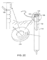
- Multiple sensor devices can be included to sense multiple characteristics. This can also allow for short isolation distances at the wellhead connection for coupling signal cables to the conductive pipe 102 as shown in Figure 2C .
- Figure 2C illustrates an exemplary alternate embodiment of a wellhead connection, wherein a spool 218 is provided to accommodate the ferrite isolator and signal connection.
- An exemplary spool can, for example, be on the order of 8 to 12 inches tall, or any other suitable size to accommodate the specific application. The spool is used for signal connection to the pipe string.
- the resonant network device configured of a "torroidal spool” can be separated and operated substantially independent of sensor packages which are similarly configured, and placed in a vicinity of the spool 218.
- An increased inductance in a width of the torroid spool can be used to isolate the signal feed point at the wellhead connection.
- current on the pipe surface will induce magnetic fields within the ferrite torroid for inductive enhancement of the pipe current path.
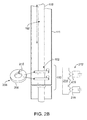
- Figure 3 illustrates a view of the Figure2A and 2B transducer from a bottom of the borehole looking upward in Figure 2 .
- the transducer 136 can be seen to be connected via, for example, electrical wires 302 to both the sensor sleeve 202 and the conductive pipe 102.
- the sensor sleeve in turn, is capacitively coupled to the hollow borehole casing 111 via the sleeve capacitance 134.
- Figure 4 illustrates an alternate exemplary embodiment wherein the packer has been modified to include a conduit extension 402 into a zone of interest where the characteristic of the borehole is to be measured.
- This extension 402 can, in an exemplary embodiment, be a direct port for sensing, for example, a pressure or temperature using an intermediate fluid to the sensor.
- transducers such as capacitive transducers, are mounted near the top of the resonant cavity as an electrical element of the sensor sleeve.
- Remote parameters can be brought to the sensor in the resonant cavity via a conduit that passes through and into a sealed sensing unit.
- the measurement of a desired parameter can then be remotely monitored.
- the monitoring can be extended using a mechanical mechanism from the sensor to relocate the sensor within the resonant cavity at different locations along the length of the conductive pipe 102.
- a sensor conduit 404 is provided to a pressure or temperature zone to be monitored.
- Figure 5 shows exemplary electronics which can be implemented in the processor 118 for providing the signal processing already described.
- the pulse generator 105 of Figure 1A provides an impulse.
- the pulse can be a narrow pulse that can be generated using a readily available off-the-shelf pulse generator.
- An exemplary pulse is on the order of 1 to 2 nanoseconds at 75 volts, having a width at half of its height on the order of 3 nanoseconds.
- a peak voltage of the pulse is on the order of 10 to 1000 volts depending on, for example, a depth of the borehole. For example, at 30,000 feet, a 1000 volt pulse can be used.
- any desired pulse of any desired characteristic can be used provided a suitable response from the resonant network device can be achieved with a desired accuracy and tolerance of the characteristic.
- a pulse section representing a pulse generator 105 of Figure 1A is provided to transmit an exemplary impulse 502. This pulse is supplied to a gated, directional coupler 504 associated with the probe 106 of Figure 1A .
- a high sensitivity receiver associated with the signal processor 118 is disabled, and the pulse is applied to the conductive pipe 102.
- the processor 118 controls the gated, directional coupler 502 to gate the receiver on and thereby detect a return from the transducer located in the resonant cavity. This return is generally depicted as the modulated vibration frequency 506.
- a timing and delay system 508 can set a delay preset (e.g., 8150 nano seconds as illustrated in Figure 5 ) to control the gating for receipt of the feedback pulse.
- the modulator vibration frequency passes through the gated directional coupler 504 and through a band pass filter unit 510.
- a filtered signal from the band pass filter unit 510 is supplied to an analog-to-digital signal recorder 512 and into a master control unit (e.g., microprocessor, such as a Pentium, or other suitable microprocessor) of the processor 118.
- a master control unit e.g., microprocessor, such as a Pentium, or other suitable microprocessor
- a telemetry/communication link system 516 can be provided to transmit information obtained from the borehole to any desired location.
- the telemetry/communication link system can be any suitable transmission and/or receiving system including, but not limited to wireless and/or wired systems.
- Figure 6 shows an exemplary method for sensing a characteristic of a borehole using, for example, an apparatus as described with respect to the preceding figure.
- an operator can set timing parameters (e.g., via the general user interface). These parameters can include, without limitation, a pulse rate, a pulse height, a received delay, and so forth.
- a pulse is supplied (e.g., fired) through the directional coupler, and into the conductive pipe of the borehole.
- the timing and delay system 508 of Figure 5 opens a receiving gate to detect the modulated vibration frequency from the transducer.
- This modulated vibration frequency constitutes a ring which enters the band pass filter in block 608, and which is recorded by the analog-to-digital recorder 512.
- a digitized signature of the ring can be processed for frequency, using, for example, a Fast Fourier Transform (FFT).
- FFT Fast Fourier Transform
- the ring frequency can be equated, through software such as look-up tablets contained within the processor 118, to a particular characteristic, or transducer parameter, and then prepared for transmission or storage.
- exemplary embodiments as described herein can provide down hole telemetry using passive techniques and resonant structures.
- the apparatus as described herein can be exposed to a hostile environment such as the high temperature and pressure of a well borehole. Minute changes in a characteristic can be detected, so that the sensitivity to changes in a desired characteristic can be readily monitored and transmitted to a receiver for processing. Because reflection of incident power is used, no downhole battery or power supply is needed, which can reduce complexity.
- fluid may be present in the well.
- Exemplary embodiments can employ techniques, such as the application of pressure, to force the fluid away from any portion of the conductive pipe and resonant cavity used for signal transmission where the fluid is expected to detrimentally influence signal detection.
- fluids which will not impact the signal detection can be forced into the borehole to replace other fluids which may be detrimental to signal detection.
Landscapes
- Engineering & Computer Science (AREA)
- Geology (AREA)
- Life Sciences & Earth Sciences (AREA)
- Mining & Mineral Resources (AREA)
- Physics & Mathematics (AREA)
- Environmental & Geological Engineering (AREA)
- Fluid Mechanics (AREA)
- General Life Sciences & Earth Sciences (AREA)
- Geochemistry & Mineralogy (AREA)
- Geophysics (AREA)
- Mechanical Engineering (AREA)
- Geophysics And Detection Of Objects (AREA)
- Measuring Fluid Pressure (AREA)
- Investigating Or Analyzing Materials By The Use Of Electric Means (AREA)
Claims (15)
- Vorrichtung (100) zum Erfassen einer Eigenschaft eines Bohrlochs, umfassend
eine leitfähige Röhre (102);
einen an die leitfähige Röhre (102) gekoppelten Einlass (104) zum Anlegen eines elektrischen Pulses an die leitfähige Röhre (102);
eine mit der leitfähigen Röhre (102) verbundene Resonanznetzvorrichtung (110); und
einen Transducer (136), in betrieblicher Verbindung mit der Resonanznetzvorrichtung (110) zum Messen einer Bohrlocheigenschaft, wobei der Transducer (136) ausgelegt ist zum Beeinflussen einer Modulation einer in der Resonanznetzvorrichtung (110) induzierten Vibrationsfrequenz eines Resonators, wird ein Puls an den Einlass (104) angelegt; und wobei der Einlass (104) zudem aufweist eine mit der leitfähigen Röhre (102) gekoppelte Sonde (106); und einen Induktor (108), um den Einlass (104) von einem gemeinsamen Erdungspotential an einem Ort in der Nähe des Einlasses (104) elektrisch zu isolieren, wobei die Resonanznetzvorrichtung (110) ein magnetisch gekoppeltes Resonanznetzwerk umfasst. - Vorrichtung gemäß Anspruch 1, umfassend
einen mit dem Einlass (104) gekoppelten Pulsgenerator (105) zum Erzeugen des an die leitfähige Röhre (102) anzulegenden Pulses. - Vorrichtung gemäß Anspruch 1, wobei der Puls eine elektrische Transiente ist.
- Vorrichtung gemäß Anspruch 1, umfassend
eine innerhalb des Bohrlochs befindliche hohle Bohrlochschalung (111), wobei mindestens ein Teil der hohlen Bohrlochschalung (111), an einer gemeinsamen Erdung ist, und wobei sich die leitfähige Röhre (102) innerhalb der hohlen Bohrlochschalung (111) befindet und elektrisch von dieser isoliert ist. - Vorrichtung gemäß Anspruch 4, wobei die leitfähige Röhre (102) über Abstandhalter (116), die sich an mehreren Anschlüssen von Röhrenabschnitten, verwendet zum Bilden der leitfähigen Röhre (102), befinden, von der hohlen Bohrlochschalung (111) elektrisch isoliert ist.
- Vorrichtung gemäß Anspruch 1, umfassend
einen mit dem Transducer (136) gekoppelten Prozessor (118) zum Bearbeiten einer Ausgabe des Transducers (136) zum Bereitstellen eines die Eigenschaft darstellenden Signals. - Vorrichtung gemäß Anspruch 1, wobei die Eigenschaft mindestens eine ist aus einer Materialzusammensetzung, einer Temperatur, einem Druck oder einer Durchflussgeschwindigkeit, wie an einem Ort entlang der Länge des Bohrlochs erfasst.
- Vorrichtung gemäß Anspruch 4, wobei die Resonanznetzvorrichtung eine resonante Vertiefung ist und die hohle Bohrlochschalung (111) an einem gemeinsamen Erdenpotential ist sowohl am Ort in der Nähe des Einlasses (104) und an einem Ort in der Nähe der resonanten Vertiefung.
- Vorrichtung gemäß Anspruch 1, wobei die Resonanznetzvorrichtung (110) eine innerhalb einer hohlen Bohrlochverschalung (111) befindliche resonante Vertiefung ist, wobei eine Länge der resonanten Vertiefung innerhalb der hohlen Bohrlochverschalung (111) definiert ist durch einen induktiven Isolator an einem ersten Ende und durch eine gemeinsame Erdungsverbindung (114) an einem zweiten Ende.
- Vorrichtung gemäß Anspruch 1, wobei der Transducer passive elektrische Bauteile aufweist.
- Verfahren zum Erfassen einer Eigenschaft eines Bohrlochs, umfassend
Übertragen eines elektrischen Pulses entlang einer innerhalb des Bohrlochs befindlichen leitfähigen Röhre (102), wobei Übertragen des Pulses umfasst Übertragen des Pulses zu einem mit der leitfähigen Röhre (102) gekoppelten Einlass (104);
Bereitstellen eines Transducers (136) in betrieblicher Verbindung mit einer Resonanznetzvorrichtung (110) zum Messen einer Bohrlocheigenschaft, wobei der Transducer (136) ausgelegt ist zum Beeinflussen einer Modulation einer in der Resonanznetzvorrichtung (110) innerhalb einer hohlen Bohrlochschalung (111) induzierten Vibrationsfrequenz eines Resonators, wird ein Puls an den Einlass (104) angelegt;
und Erfassen der modulierten Vibrationsfrequenz, als Messgröße der Bohrlocheigenschaft; wobei der Einlass (104) zudem aufweist eine mit der leitfähigen Röhre (102) gekoppelte Sonde (106); und einen Induktor (108), um den Einlass (104) von einem gemeinsamen Erdungspotential an einem Ort in der Nähe des Einlasses (104) elektrisch zu isolieren, wobei die Resonanznetzvorrichtung (110) ein magnetisch gekoppeltes Resonanznetzwerk umfasst. - Verfahren gemäß Anspruch 11, umfassend
Bearbeiten der Modulation der Vibrationsfrequenz zum Bereitstellen eines Signals, das die Eigenschaft darstellt. - Verfahren gemäß Anspruch 12, wobei die Eigenschaft mindestens eine ist aus einer Materialzusammensetzung, einer Temperatur, einem Druck oder einer Durchflussgeschwindigkeit, wie an einem Ort entlang der Länge des Bohrlochs erfasst.
- Verfahren gemäß Anspruch 11, wobei das Bearbeiten aufweist
Durchführen einer statistischen Analyse der modulierten Vibrationsfrequenz. - Verfahren gemäß Anspruch 11, umfassend
Kalibrieren eines Transducers (136), verwendet zum Herstellen der modulierten Vibrationsfrequenz vor dem Einführen des Sensors in das Bohrloch.
Applications Claiming Priority (2)
| Application Number | Priority Date | Filing Date | Title |
|---|---|---|---|
| US11/394,186 US8077053B2 (en) | 2006-03-31 | 2006-03-31 | Method and apparatus for sensing a borehole characteristic |
| PCT/US2007/063909 WO2007117846A2 (en) | 2006-03-31 | 2007-03-13 | Method and apparatus for sensing a borehole characteristic |
Publications (3)
| Publication Number | Publication Date |
|---|---|
| EP2005221A2 EP2005221A2 (de) | 2008-12-24 |
| EP2005221A4 EP2005221A4 (de) | 2012-04-18 |
| EP2005221B1 true EP2005221B1 (de) | 2015-09-30 |
Family
ID=38573923
Family Applications (1)
| Application Number | Title | Priority Date | Filing Date |
|---|---|---|---|
| EP07758461.3A Not-in-force EP2005221B1 (de) | 2006-03-31 | 2007-03-13 | Verfahren und vorrichtung zur messung einer bohrlocheigenschaft |
Country Status (10)
| Country | Link |
|---|---|
| US (1) | US8077053B2 (de) |
| EP (1) | EP2005221B1 (de) |
| JP (1) | JP2009532677A (de) |
| CN (1) | CN101410728B (de) |
| AU (1) | AU2007235108B2 (de) |
| BR (1) | BRPI0709918B1 (de) |
| CA (1) | CA2646145C (de) |
| MY (1) | MY150883A (de) |
| RU (1) | RU2431039C2 (de) |
| WO (1) | WO2007117846A2 (de) |
Families Citing this family (30)
| Publication number | Priority date | Publication date | Assignee | Title |
|---|---|---|---|---|
| US20080007426A1 (en) * | 2006-06-13 | 2008-01-10 | Itron, Inc | Modified use of a standard message protocol for inter-module communications within a utility meter |
| EP2069828A2 (de) | 2006-09-08 | 2009-06-17 | Chevron U.S.A. Inc. | Telemetrievorrichtung und verfahren zur überwachung eines bohrlochs |
| US7810993B2 (en) * | 2007-02-06 | 2010-10-12 | Chevron U.S.A. Inc. | Temperature sensor having a rotational response to the environment |
| US7863907B2 (en) * | 2007-02-06 | 2011-01-04 | Chevron U.S.A. Inc. | Temperature and pressure transducer |
| US7841234B2 (en) * | 2007-07-30 | 2010-11-30 | Chevron U.S.A. Inc. | System and method for sensing pressure using an inductive element |
| US9547104B2 (en) * | 2007-09-04 | 2017-01-17 | Chevron U.S.A. Inc. | Downhole sensor interrogation employing coaxial cable |
| US7636052B2 (en) | 2007-12-21 | 2009-12-22 | Chevron U.S.A. Inc. | Apparatus and method for monitoring acoustic energy in a borehole |
| EP2324375A2 (de) * | 2009-07-17 | 2011-05-25 | Baker Hughes Incorporated | Radiale wellen in einem bohrloch und stoneley-wellen zur messung einer formationsdurchlässigkeit und einer elektroakustischen konstante |
| US8353677B2 (en) * | 2009-10-05 | 2013-01-15 | Chevron U.S.A. Inc. | System and method for sensing a liquid level |
| US8575936B2 (en) | 2009-11-30 | 2013-11-05 | Chevron U.S.A. Inc. | Packer fluid and system and method for remote sensing |
| US10488286B2 (en) * | 2009-11-30 | 2019-11-26 | Chevron U.S.A. Inc. | System and method for measurement incorporating a crystal oscillator |
| US20110187554A1 (en) * | 2010-01-29 | 2011-08-04 | Schlumberger Technology Corporation | Integrated permanent monitoring system |
| BR112013011709B1 (pt) * | 2010-11-12 | 2020-10-06 | Chevron U.S.A. Inc | Sistema e método para sensor remoto |
| US9103198B2 (en) * | 2010-11-12 | 2015-08-11 | Chevron U.S.A. Inc. | System and method for remote sensing |
| US9097101B2 (en) * | 2012-03-29 | 2015-08-04 | Chevron U.S.A Inc. | System and method for measurement incorporating a crystal resonator |
| US9201156B2 (en) * | 2012-03-29 | 2015-12-01 | Chevron U.S.A. Inc. | System and method for measurement incorporating a crystal resonator |
| WO2014084889A1 (en) | 2012-11-29 | 2014-06-05 | Chevron U.S.A. Inc. | Transmitting power within a wellbore |
| US8857522B2 (en) | 2012-11-29 | 2014-10-14 | Chevron U.S.A., Inc. | Electrically-powered surface-controlled subsurface safety valves |
| US9534489B2 (en) * | 2013-03-06 | 2017-01-03 | Baker Hughes Incorporated | Modeling acid distribution for acid stimulation of a formation |
| AU2013399119B2 (en) | 2013-08-29 | 2017-05-04 | Halliburton Energy Services, Inc. | Systems and methods for casing detection using resonant structures |
| US9920581B2 (en) * | 2014-02-24 | 2018-03-20 | Baker Hughes, A Ge Company, Llc | Electromagnetic directional coupler wired pipe transmission device |
| US9267334B2 (en) | 2014-05-22 | 2016-02-23 | Chevron U.S.A. Inc. | Isolator sub |
| US9828848B2 (en) * | 2014-10-09 | 2017-11-28 | Baker Hughes, A Ge Company, Llc | Wireless passive pressure sensor for downhole annulus monitoring |
| WO2016064421A1 (en) * | 2014-10-24 | 2016-04-28 | Halliburton Energy Services, Inc. | Acoustic dipole piston transmitter |
| WO2016149811A1 (en) * | 2015-03-20 | 2016-09-29 | Cenovus Energy Inc. | Hydrocarbon production apparatus |
| CN105003249B (zh) * | 2015-08-06 | 2020-09-25 | 北京航空航天大学 | 一种基于总流量与电导探针阵列信号的水平井流型识别方法 |
| US11163086B2 (en) | 2017-01-10 | 2021-11-02 | University Of Houston System | Apparatus and method for wellbore imaging in oil-based mud |
| US11280745B2 (en) | 2018-07-05 | 2022-03-22 | Mezent Corporation | Resonant sensing device |
| KR102263232B1 (ko) * | 2019-05-21 | 2021-06-10 | (주)케이에스엠 | 광산 및 건설, 유전 시추용 로드 파이프를 통한 주파수 변조 기반의 센서 데이터 전송방법 및 장치 |
| CN110847894B (zh) * | 2019-10-30 | 2022-11-04 | 中国石油天然气股份有限公司 | 一种井下节流气井流压的确定方法 |
Family Cites Families (22)
| Publication number | Priority date | Publication date | Assignee | Title |
|---|---|---|---|---|
| US3906434A (en) * | 1971-02-08 | 1975-09-16 | American Petroscience Corp | Telemetering system for oil wells |
| FR2467414A1 (fr) * | 1979-10-11 | 1981-04-17 | Anvar | Procede et dispositif de reconnaissance de sols et de milieux rocheux |
| US4710713A (en) * | 1986-03-11 | 1987-12-01 | Numar Corporation | Nuclear magnetic resonance sensing apparatus and techniques |
| NO163578C (no) * | 1987-10-23 | 1990-06-20 | Saga Petroleum | Fremgangsmaate og innretning for overfoering av maaledata fra en oljebroenn til overflaten. |
| US4834210A (en) * | 1987-12-21 | 1989-05-30 | Western Atlas International, Inc. | Apparatus for generating seismic waves |
| US4993001A (en) * | 1988-03-04 | 1991-02-12 | Exxon Production Research Company | Method and apparatus for converting tube waves to body waves for seismic exploration |
| US4962489A (en) * | 1989-03-31 | 1990-10-09 | Mobil Oil Corporation | Acoustic borehole logging |
| US5406530A (en) * | 1992-03-20 | 1995-04-11 | Kawasaki Steel Corporation | Pseudo-random binary sequence measurement method |
| US5268537A (en) * | 1992-06-29 | 1993-12-07 | Exxon Production Research Company | Broadband resonant wave downhole seismic source |
| RU2044878C1 (ru) * | 1993-03-31 | 1995-09-27 | Сибирский научно-исследовательский институт нефтяной промышленности | Телеметрическая система для контроля числа оборотов вала турбобура |
| FR2713869B1 (fr) * | 1993-12-10 | 1996-01-26 | Inst Francais Du Petrole | Transducteur électro-acoustique à transformateur mécanique d'impédance. |
| US5901113A (en) * | 1996-03-12 | 1999-05-04 | Schlumberger Technology Corporation | Inverse vertical seismic profiling using a measurement while drilling tool as a seismic source |
| JP3374652B2 (ja) * | 1996-05-07 | 2003-02-10 | 三菱電機株式会社 | 掘削管体伝送用弾性波発生装置 |
| US6388577B1 (en) * | 1997-04-07 | 2002-05-14 | Kenneth J. Carstensen | High impact communication and control system |
| US5886303A (en) * | 1997-10-20 | 1999-03-23 | Dresser Industries, Inc. | Method and apparatus for cancellation of unwanted signals in MWD acoustic tools |
| US6172614B1 (en) * | 1998-07-13 | 2001-01-09 | Halliburton Energy Services, Inc. | Method and apparatus for remote actuation of a downhole device using a resonant chamber |
| US6456566B1 (en) * | 2000-07-21 | 2002-09-24 | Baker Hughes Incorporated | Use of minor borehole obstructions as seismic sources |
| US6434372B1 (en) * | 2001-01-12 | 2002-08-13 | The Regents Of The University Of California | Long-range, full-duplex, modulated-reflector cell phone for voice/data transmission |
| US6937159B2 (en) * | 2001-02-02 | 2005-08-30 | Dbi Corporation | Downhole telemetry and control system using orthogonal frequency division multiplexing |
| US6626253B2 (en) * | 2001-02-27 | 2003-09-30 | Baker Hughes Incorporated | Oscillating shear valve for mud pulse telemetry |
| US6795373B1 (en) * | 2003-02-14 | 2004-09-21 | Baker Hughes Incorporated | Permanent downhole resonant source |
| US7222671B2 (en) * | 2004-12-23 | 2007-05-29 | Schlumberger Technology Corporation | Apparatus and method for formation evaluation |
-
2006
- 2006-03-31 US US11/394,186 patent/US8077053B2/en active Active
-
2007
- 2007-03-13 CA CA2646145A patent/CA2646145C/en not_active Expired - Fee Related
- 2007-03-13 RU RU2008143266/03A patent/RU2431039C2/ru not_active IP Right Cessation
- 2007-03-13 EP EP07758461.3A patent/EP2005221B1/de not_active Not-in-force
- 2007-03-13 MY MYPI20083685 patent/MY150883A/en unknown
- 2007-03-13 BR BRPI0709918-5A patent/BRPI0709918B1/pt not_active IP Right Cessation
- 2007-03-13 CN CN2007800115499A patent/CN101410728B/zh not_active Expired - Fee Related
- 2007-03-13 WO PCT/US2007/063909 patent/WO2007117846A2/en not_active Ceased
- 2007-03-13 AU AU2007235108A patent/AU2007235108B2/en not_active Ceased
- 2007-03-13 JP JP2009503136A patent/JP2009532677A/ja active Pending
Also Published As
| Publication number | Publication date |
|---|---|
| MY150883A (en) | 2014-03-14 |
| CN101410728A (zh) | 2009-04-15 |
| CN101410728B (zh) | 2013-07-10 |
| CA2646145C (en) | 2017-07-11 |
| BRPI0709918B1 (pt) | 2019-02-12 |
| RU2431039C2 (ru) | 2011-10-10 |
| WO2007117846A3 (en) | 2008-07-31 |
| EP2005221A2 (de) | 2008-12-24 |
| EP2005221A4 (de) | 2012-04-18 |
| CA2646145A1 (en) | 2007-10-18 |
| AU2007235108A1 (en) | 2007-10-18 |
| AU2007235108B2 (en) | 2013-04-18 |
| RU2008143266A (ru) | 2010-05-10 |
| JP2009532677A (ja) | 2009-09-10 |
| BRPI0709918A2 (pt) | 2011-07-26 |
| US20070235184A1 (en) | 2007-10-11 |
| US8077053B2 (en) | 2011-12-13 |
| WO2007117846A2 (en) | 2007-10-18 |
Similar Documents
| Publication | Publication Date | Title |
|---|---|---|
| EP2005221B1 (de) | Verfahren und vorrichtung zur messung einer bohrlocheigenschaft | |
| CA2683442C (en) | System and method for receiving and decoding electromagnetic transmissions within a well | |
| CA2663043C (en) | A telemetry apparatus and method for monitoring a borehole | |
| US7530737B2 (en) | System and method for measuring temperature using electromagnetic transmissions within a well | |
| EP3384130B1 (de) | Sensor | |
| US20120211278A1 (en) | System and method for remote sensing | |
| CN104204861A (zh) | 用于结合晶体共振器进行测量的系统和方法 | |
| EP1276968B1 (de) | Messgeräte zur verwendung in bohrlöchern | |
| US20140375467A1 (en) | Wireless Transmission of Well Formation Information | |
| WO2013142484A2 (en) | Apparatus and method for remotely determining the structural intergrity of a well or similar structure |
Legal Events
| Date | Code | Title | Description |
|---|---|---|---|
| PUAI | Public reference made under article 153(3) epc to a published international application that has entered the european phase |
Free format text: ORIGINAL CODE: 0009012 |
|
| 17P | Request for examination filed |
Effective date: 20081027 |
|
| AK | Designated contracting states |
Kind code of ref document: A2 Designated state(s): AT BE BG CH CY CZ DE DK EE ES FI FR GB GR HU IE IS IT LI LT LU LV MC MT NL PL PT RO SE SI SK TR |
|
| AX | Request for extension of the european patent |
Extension state: AL BA HR MK RS |
|
| A4 | Supplementary search report drawn up and despatched |
Effective date: 20120320 |
|
| RIC1 | Information provided on ipc code assigned before grant |
Ipc: G01V 13/00 20060101AFI20120314BHEP |
|
| 17Q | First examination report despatched |
Effective date: 20120423 |
|
| DAX | Request for extension of the european patent (deleted) | ||
| GRAP | Despatch of communication of intention to grant a patent |
Free format text: ORIGINAL CODE: EPIDOSNIGR1 |
|
| INTG | Intention to grant announced |
Effective date: 20150505 |
|
| RAP1 | Party data changed (applicant data changed or rights of an application transferred) |
Owner name: CHEVRON U.S.A. INC. |
|
| GRAS | Grant fee paid |
Free format text: ORIGINAL CODE: EPIDOSNIGR3 |
|
| GRAA | (expected) grant |
Free format text: ORIGINAL CODE: 0009210 |
|
| AK | Designated contracting states |
Kind code of ref document: B1 Designated state(s): AT BE BG CH CY CZ DE DK EE ES FI FR GB GR HU IE IS IT LI LT LU LV MC MT NL PL PT RO SE SI SK TR |
|
| REG | Reference to a national code |
Ref country code: CH Ref legal event code: EP Ref country code: GB Ref legal event code: FG4D |
|
| REG | Reference to a national code |
Ref country code: AT Ref legal event code: REF Ref document number: 752743 Country of ref document: AT Kind code of ref document: T Effective date: 20151015 |
|
| REG | Reference to a national code |
Ref country code: IE Ref legal event code: FG4D |
|
| REG | Reference to a national code |
Ref country code: DE Ref legal event code: R096 Ref document number: 602007043321 Country of ref document: DE |
|
| PG25 | Lapsed in a contracting state [announced via postgrant information from national office to epo] |
Ref country code: GR Free format text: LAPSE BECAUSE OF FAILURE TO SUBMIT A TRANSLATION OF THE DESCRIPTION OR TO PAY THE FEE WITHIN THE PRESCRIBED TIME-LIMIT Effective date: 20151231 Ref country code: LV Free format text: LAPSE BECAUSE OF FAILURE TO SUBMIT A TRANSLATION OF THE DESCRIPTION OR TO PAY THE FEE WITHIN THE PRESCRIBED TIME-LIMIT Effective date: 20150930 Ref country code: LT Free format text: LAPSE BECAUSE OF FAILURE TO SUBMIT A TRANSLATION OF THE DESCRIPTION OR TO PAY THE FEE WITHIN THE PRESCRIBED TIME-LIMIT Effective date: 20150930 Ref country code: FI Free format text: LAPSE BECAUSE OF FAILURE TO SUBMIT A TRANSLATION OF THE DESCRIPTION OR TO PAY THE FEE WITHIN THE PRESCRIBED TIME-LIMIT Effective date: 20150930 |
|
| REG | Reference to a national code |
Ref country code: NL Ref legal event code: MP Effective date: 20150930 |
|
| REG | Reference to a national code |
Ref country code: LT Ref legal event code: MG4D |
|
| REG | Reference to a national code |
Ref country code: AT Ref legal event code: MK05 Ref document number: 752743 Country of ref document: AT Kind code of ref document: T Effective date: 20150930 |
|
| PG25 | Lapsed in a contracting state [announced via postgrant information from national office to epo] |
Ref country code: SE Free format text: LAPSE BECAUSE OF FAILURE TO SUBMIT A TRANSLATION OF THE DESCRIPTION OR TO PAY THE FEE WITHIN THE PRESCRIBED TIME-LIMIT Effective date: 20150930 |
|
| PG25 | Lapsed in a contracting state [announced via postgrant information from national office to epo] |
Ref country code: CZ Free format text: LAPSE BECAUSE OF FAILURE TO SUBMIT A TRANSLATION OF THE DESCRIPTION OR TO PAY THE FEE WITHIN THE PRESCRIBED TIME-LIMIT Effective date: 20150930 Ref country code: IT Free format text: LAPSE BECAUSE OF FAILURE TO SUBMIT A TRANSLATION OF THE DESCRIPTION OR TO PAY THE FEE WITHIN THE PRESCRIBED TIME-LIMIT Effective date: 20150930 Ref country code: IS Free format text: LAPSE BECAUSE OF FAILURE TO SUBMIT A TRANSLATION OF THE DESCRIPTION OR TO PAY THE FEE WITHIN THE PRESCRIBED TIME-LIMIT Effective date: 20160130 Ref country code: SK Free format text: LAPSE BECAUSE OF FAILURE TO SUBMIT A TRANSLATION OF THE DESCRIPTION OR TO PAY THE FEE WITHIN THE PRESCRIBED TIME-LIMIT Effective date: 20150930 Ref country code: NL Free format text: LAPSE BECAUSE OF FAILURE TO SUBMIT A TRANSLATION OF THE DESCRIPTION OR TO PAY THE FEE WITHIN THE PRESCRIBED TIME-LIMIT Effective date: 20150930 Ref country code: EE Free format text: LAPSE BECAUSE OF FAILURE TO SUBMIT A TRANSLATION OF THE DESCRIPTION OR TO PAY THE FEE WITHIN THE PRESCRIBED TIME-LIMIT Effective date: 20150930 Ref country code: ES Free format text: LAPSE BECAUSE OF FAILURE TO SUBMIT A TRANSLATION OF THE DESCRIPTION OR TO PAY THE FEE WITHIN THE PRESCRIBED TIME-LIMIT Effective date: 20150930 |
|
| PG25 | Lapsed in a contracting state [announced via postgrant information from national office to epo] |
Ref country code: PL Free format text: LAPSE BECAUSE OF FAILURE TO SUBMIT A TRANSLATION OF THE DESCRIPTION OR TO PAY THE FEE WITHIN THE PRESCRIBED TIME-LIMIT Effective date: 20150930 Ref country code: PT Free format text: LAPSE BECAUSE OF FAILURE TO SUBMIT A TRANSLATION OF THE DESCRIPTION OR TO PAY THE FEE WITHIN THE PRESCRIBED TIME-LIMIT Effective date: 20160201 Ref country code: RO Free format text: LAPSE BECAUSE OF FAILURE TO SUBMIT A TRANSLATION OF THE DESCRIPTION OR TO PAY THE FEE WITHIN THE PRESCRIBED TIME-LIMIT Effective date: 20150930 Ref country code: AT Free format text: LAPSE BECAUSE OF FAILURE TO SUBMIT A TRANSLATION OF THE DESCRIPTION OR TO PAY THE FEE WITHIN THE PRESCRIBED TIME-LIMIT Effective date: 20150930 |
|
| REG | Reference to a national code |
Ref country code: DE Ref legal event code: R097 Ref document number: 602007043321 Country of ref document: DE |
|
| PLBE | No opposition filed within time limit |
Free format text: ORIGINAL CODE: 0009261 |
|
| STAA | Information on the status of an ep patent application or granted ep patent |
Free format text: STATUS: NO OPPOSITION FILED WITHIN TIME LIMIT |
|
| PG25 | Lapsed in a contracting state [announced via postgrant information from national office to epo] |
Ref country code: BE Free format text: LAPSE BECAUSE OF NON-PAYMENT OF DUE FEES Effective date: 20160331 Ref country code: DK Free format text: LAPSE BECAUSE OF FAILURE TO SUBMIT A TRANSLATION OF THE DESCRIPTION OR TO PAY THE FEE WITHIN THE PRESCRIBED TIME-LIMIT Effective date: 20150930 |
|
| 26N | No opposition filed |
Effective date: 20160701 |
|
| REG | Reference to a national code |
Ref country code: DE Ref legal event code: R119 Ref document number: 602007043321 Country of ref document: DE |
|
| PG25 | Lapsed in a contracting state [announced via postgrant information from national office to epo] |
Ref country code: LU Free format text: LAPSE BECAUSE OF FAILURE TO SUBMIT A TRANSLATION OF THE DESCRIPTION OR TO PAY THE FEE WITHIN THE PRESCRIBED TIME-LIMIT Effective date: 20160313 Ref country code: MC Free format text: LAPSE BECAUSE OF FAILURE TO SUBMIT A TRANSLATION OF THE DESCRIPTION OR TO PAY THE FEE WITHIN THE PRESCRIBED TIME-LIMIT Effective date: 20150930 |
|
| REG | Reference to a national code |
Ref country code: CH Ref legal event code: PL |
|
| PG25 | Lapsed in a contracting state [announced via postgrant information from national office to epo] |
Ref country code: SI Free format text: LAPSE BECAUSE OF FAILURE TO SUBMIT A TRANSLATION OF THE DESCRIPTION OR TO PAY THE FEE WITHIN THE PRESCRIBED TIME-LIMIT Effective date: 20150930 |
|
| REG | Reference to a national code |
Ref country code: IE Ref legal event code: MM4A |
|
| PG25 | Lapsed in a contracting state [announced via postgrant information from national office to epo] |
Ref country code: BE Free format text: LAPSE BECAUSE OF FAILURE TO SUBMIT A TRANSLATION OF THE DESCRIPTION OR TO PAY THE FEE WITHIN THE PRESCRIBED TIME-LIMIT Effective date: 20150930 |
|
| REG | Reference to a national code |
Ref country code: FR Ref legal event code: ST Effective date: 20161130 |
|
| PG25 | Lapsed in a contracting state [announced via postgrant information from national office to epo] |
Ref country code: DE Free format text: LAPSE BECAUSE OF NON-PAYMENT OF DUE FEES Effective date: 20161001 Ref country code: FR Free format text: LAPSE BECAUSE OF NON-PAYMENT OF DUE FEES Effective date: 20160331 Ref country code: LI Free format text: LAPSE BECAUSE OF NON-PAYMENT OF DUE FEES Effective date: 20160331 Ref country code: IE Free format text: LAPSE BECAUSE OF NON-PAYMENT OF DUE FEES Effective date: 20160313 Ref country code: CH Free format text: LAPSE BECAUSE OF NON-PAYMENT OF DUE FEES Effective date: 20160331 |
|
| PG25 | Lapsed in a contracting state [announced via postgrant information from national office to epo] |
Ref country code: MT Free format text: LAPSE BECAUSE OF FAILURE TO SUBMIT A TRANSLATION OF THE DESCRIPTION OR TO PAY THE FEE WITHIN THE PRESCRIBED TIME-LIMIT Effective date: 20150930 |
|
| PG25 | Lapsed in a contracting state [announced via postgrant information from national office to epo] |
Ref country code: CY Free format text: LAPSE BECAUSE OF FAILURE TO SUBMIT A TRANSLATION OF THE DESCRIPTION OR TO PAY THE FEE WITHIN THE PRESCRIBED TIME-LIMIT Effective date: 20150930 Ref country code: HU Free format text: LAPSE BECAUSE OF FAILURE TO SUBMIT A TRANSLATION OF THE DESCRIPTION OR TO PAY THE FEE WITHIN THE PRESCRIBED TIME-LIMIT; INVALID AB INITIO Effective date: 20070313 |
|
| PG25 | Lapsed in a contracting state [announced via postgrant information from national office to epo] |
Ref country code: MT Free format text: LAPSE BECAUSE OF FAILURE TO SUBMIT A TRANSLATION OF THE DESCRIPTION OR TO PAY THE FEE WITHIN THE PRESCRIBED TIME-LIMIT Effective date: 20160331 Ref country code: TR Free format text: LAPSE BECAUSE OF FAILURE TO SUBMIT A TRANSLATION OF THE DESCRIPTION OR TO PAY THE FEE WITHIN THE PRESCRIBED TIME-LIMIT Effective date: 20150930 |
|
| PG25 | Lapsed in a contracting state [announced via postgrant information from national office to epo] |
Ref country code: BG Free format text: LAPSE BECAUSE OF FAILURE TO SUBMIT A TRANSLATION OF THE DESCRIPTION OR TO PAY THE FEE WITHIN THE PRESCRIBED TIME-LIMIT Effective date: 20150930 |
|
| PGFP | Annual fee paid to national office [announced via postgrant information from national office to epo] |
Ref country code: GB Payment date: 20200304 Year of fee payment: 14 |
|
| GBPC | Gb: european patent ceased through non-payment of renewal fee |
Effective date: 20210313 |
|
| PG25 | Lapsed in a contracting state [announced via postgrant information from national office to epo] |
Ref country code: GB Free format text: LAPSE BECAUSE OF NON-PAYMENT OF DUE FEES Effective date: 20210313 |
|
| P01 | Opt-out of the competence of the unified patent court (upc) registered |
Effective date: 20230524 |