EP2004540B1 - Self-contained single dose dual fluid dispenser - Google Patents
Self-contained single dose dual fluid dispenser Download PDFInfo
- Publication number
- EP2004540B1 EP2004540B1 EP07753641.5A EP07753641A EP2004540B1 EP 2004540 B1 EP2004540 B1 EP 2004540B1 EP 07753641 A EP07753641 A EP 07753641A EP 2004540 B1 EP2004540 B1 EP 2004540B1
- Authority
- EP
- European Patent Office
- Prior art keywords
- piston
- single dose
- force
- dual fluid
- dual
- Prior art date
- Legal status (The legal status is an assumption and is not a legal conclusion. Google has not performed a legal analysis and makes no representation as to the accuracy of the status listed.)
- Ceased
Links
- 239000012530 fluid Substances 0.000 title claims description 181
- 230000009977 dual effect Effects 0.000 title claims description 95
- 230000005540 biological transmission Effects 0.000 claims description 17
- 239000007795 chemical reaction product Substances 0.000 claims description 16
- 238000000034 method Methods 0.000 claims description 13
- 238000002156 mixing Methods 0.000 claims description 11
- 238000005381 potential energy Methods 0.000 claims description 11
- 238000003825 pressing Methods 0.000 claims description 6
- 230000003213 activating effect Effects 0.000 claims 1
- 230000004913 activation Effects 0.000 claims 1
- 230000002028 premature Effects 0.000 claims 1
- 230000006835 compression Effects 0.000 description 10
- 238000007906 compression Methods 0.000 description 10
- 230000003068 static effect Effects 0.000 description 6
- 239000002699 waste material Substances 0.000 description 6
- 230000008901 benefit Effects 0.000 description 4
- 230000033001 locomotion Effects 0.000 description 4
- 239000000899 Gutta-Percha Substances 0.000 description 2
- 240000000342 Palaquium gutta Species 0.000 description 2
- 239000000853 adhesive Substances 0.000 description 2
- 230000001070 adhesive effect Effects 0.000 description 2
- 238000005429 filling process Methods 0.000 description 2
- 229920000588 gutta-percha Polymers 0.000 description 2
- 238000013038 hand mixing Methods 0.000 description 2
- 239000004848 polyfunctional curative Substances 0.000 description 2
- 239000011347 resin Substances 0.000 description 2
- 229920005989 resin Polymers 0.000 description 2
- 238000013022 venting Methods 0.000 description 2
- 244000052616 bacterial pathogen Species 0.000 description 1
- 238000004891 communication Methods 0.000 description 1
- 208000015181 infectious disease Diseases 0.000 description 1
- 239000002245 particle Substances 0.000 description 1
- 238000009877 rendering Methods 0.000 description 1
- 238000007789 sealing Methods 0.000 description 1
Images




Classifications
-
- B—PERFORMING OPERATIONS; TRANSPORTING
- B67—OPENING, CLOSING OR CLEANING BOTTLES, JARS OR SIMILAR CONTAINERS; LIQUID HANDLING
- B67D—DISPENSING, DELIVERING OR TRANSFERRING LIQUIDS, NOT OTHERWISE PROVIDED FOR
- B67D7/00—Apparatus or devices for transferring liquids from bulk storage containers or reservoirs into vehicles or into portable containers, e.g. for retail sale purposes
- B67D7/06—Details or accessories
- B67D7/78—Arrangements of storage tanks, reservoirs or pipe-lines
-
- A—HUMAN NECESSITIES
- A61—MEDICAL OR VETERINARY SCIENCE; HYGIENE
- A61B—DIAGNOSIS; SURGERY; IDENTIFICATION
- A61B17/00—Surgical instruments, devices or methods
- A61B17/00491—Surgical glue applicators
-
- A—HUMAN NECESSITIES
- A61—MEDICAL OR VETERINARY SCIENCE; HYGIENE
- A61C—DENTISTRY; APPARATUS OR METHODS FOR ORAL OR DENTAL HYGIENE
- A61C5/00—Filling or capping teeth
- A61C5/60—Devices specially adapted for pressing or mixing capping or filling materials, e.g. amalgam presses
- A61C5/62—Applicators, e.g. syringes or guns
-
- A—HUMAN NECESSITIES
- A61—MEDICAL OR VETERINARY SCIENCE; HYGIENE
- A61C—DENTISTRY; APPARATUS OR METHODS FOR ORAL OR DENTAL HYGIENE
- A61C5/00—Filling or capping teeth
- A61C5/60—Devices specially adapted for pressing or mixing capping or filling materials, e.g. amalgam presses
- A61C5/62—Applicators, e.g. syringes or guns
- A61C5/64—Applicators, e.g. syringes or guns for multi-component compositions
-
- A—HUMAN NECESSITIES
- A61—MEDICAL OR VETERINARY SCIENCE; HYGIENE
- A61M—DEVICES FOR INTRODUCING MEDIA INTO, OR ONTO, THE BODY; DEVICES FOR TRANSDUCING BODY MEDIA OR FOR TAKING MEDIA FROM THE BODY; DEVICES FOR PRODUCING OR ENDING SLEEP OR STUPOR
- A61M5/00—Devices for bringing media into the body in a subcutaneous, intra-vascular or intramuscular way; Accessories therefor, e.g. filling or cleaning devices, arm-rests
- A61M5/178—Syringes
- A61M5/31—Details
- A61M5/315—Pistons; Piston-rods; Guiding, blocking or restricting the movement of the rod or piston; Appliances on the rod for facilitating dosing ; Dosing mechanisms
-
- B—PERFORMING OPERATIONS; TRANSPORTING
- B01—PHYSICAL OR CHEMICAL PROCESSES OR APPARATUS IN GENERAL
- B01F—MIXING, e.g. DISSOLVING, EMULSIFYING OR DISPERSING
- B01F25/00—Flow mixers; Mixers for falling materials, e.g. solid particles
- B01F25/40—Static mixers
-
- B—PERFORMING OPERATIONS; TRANSPORTING
- B01—PHYSICAL OR CHEMICAL PROCESSES OR APPARATUS IN GENERAL
- B01F—MIXING, e.g. DISSOLVING, EMULSIFYING OR DISPERSING
- B01F35/00—Accessories for mixers; Auxiliary operations or auxiliary devices; Parts or details of general application
- B01F35/80—Forming a predetermined ratio of the substances to be mixed
-
- B—PERFORMING OPERATIONS; TRANSPORTING
- B65—CONVEYING; PACKING; STORING; HANDLING THIN OR FILAMENTARY MATERIAL
- B65D—CONTAINERS FOR STORAGE OR TRANSPORT OF ARTICLES OR MATERIALS, e.g. BAGS, BARRELS, BOTTLES, BOXES, CANS, CARTONS, CRATES, DRUMS, JARS, TANKS, HOPPERS, FORWARDING CONTAINERS; ACCESSORIES, CLOSURES, OR FITTINGS THEREFOR; PACKAGING ELEMENTS; PACKAGES
- B65D88/00—Large containers
- B65D88/54—Large containers characterised by means facilitating filling or emptying
-
- A—HUMAN NECESSITIES
- A61—MEDICAL OR VETERINARY SCIENCE; HYGIENE
- A61B—DIAGNOSIS; SURGERY; IDENTIFICATION
- A61B17/00—Surgical instruments, devices or methods
- A61B17/00491—Surgical glue applicators
- A61B2017/00495—Surgical glue applicators for two-component glue
-
- B—PERFORMING OPERATIONS; TRANSPORTING
- B05—SPRAYING OR ATOMISING IN GENERAL; APPLYING FLUENT MATERIALS TO SURFACES, IN GENERAL
- B05C—APPARATUS FOR APPLYING FLUENT MATERIALS TO SURFACES, IN GENERAL
- B05C17/00—Hand tools or apparatus using hand held tools, for applying liquids or other fluent materials to, for spreading applied liquids or other fluent materials on, or for partially removing applied liquids or other fluent materials from, surfaces
- B05C17/005—Hand tools or apparatus using hand held tools, for applying liquids or other fluent materials to, for spreading applied liquids or other fluent materials on, or for partially removing applied liquids or other fluent materials from, surfaces for discharging material from a reservoir or container located in or on the hand tool through an outlet orifice by pressure without using surface contacting members like pads or brushes
- B05C17/00553—Hand tools or apparatus using hand held tools, for applying liquids or other fluent materials to, for spreading applied liquids or other fluent materials on, or for partially removing applied liquids or other fluent materials from, surfaces for discharging material from a reservoir or container located in or on the hand tool through an outlet orifice by pressure without using surface contacting members like pads or brushes with means allowing the stock of material to consist of at least two different components
Definitions
- a dual fluid chemically reactive component i.e. a resin and a hardener
- the dental field is an example of such a field.
- dental practitioners prefer using dispensers that can be disposed of after use with one patient. These are typically referred to as single dose dispensers.
- Single dose dispensers provide several significant advantages over multi-use dispensers. Single dose dispensers are more sanitary than multi-use dispensers. With a single use dispenser, the dental practitioner can dispose of the dispenser after the procedure is complete; thereby, reducing the possibility of spreading germs and infection among patients. Also, single dose dispensers do not have as much waste as multi-use dispensers.
- the resin and hardener components often times cross-contaminate between uses, causing the adhesive to harden and rendering the dispenser useless.
- the dental practitioner is only able to get two to three uses out of the multi-use dispenser and does not achieve the benefit of using the dispenser multiple times.
- single dose dispensers because they are smaller, are much easier to work with and manipulate, especially in the confined space of a patient's mouth.
- the container contains gutta-percha in particle form and a sealer.
- the practitioner breaks the seal separating the gutta-percha from the sealer and mixes the entire contents of the two components together in a standard triturator.
- a single batch of the end product is made and can be dispensed for use.
- the components of the end product are all mixed together at one time and are not mixed together only as needed as they are dispensed from the cartridge.
- a self-contained single dose dual fluid dispenser to store and dispense two fluids includes a dual fluid container having an outer cartridge wall defining an outlet and an open end opposite the outlet.
- the dual fluid dispenser also includes a delivery tube disposed within the outer cartridge wall and defines an outlet that is co-located with the outlet defined by the outer cartridge wall; a first piston disposed between the outer cartridge wall and the delivery tube which forms a fluid chamber for a single dose of a first fluid and a second piston disposed within the outer cartridge wall between the first piston and the open end of the outer cartridge wall.
- the dual fluid dispenser further includes a fixed wall disposed between the first piston and the second piston, wherein the fixed wall and the second piston define a fluid chamber for a single dose of a second fluid.
- a force providing mechanism is disposed within the open end of and attached to the dual fluid container, wherein, when activated, the force providing mechanism applies a force to the second piston.
- a transmission structure disposed between the second piston and the first piston.
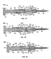
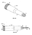
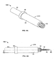
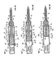
- Figs. 1A-1E , 2A-2E , 3A-3E and 4A-4E illustrate four different embodiments of self-contained, single dose, dual fluid dispensers 10A-10D .
- the embodiments depicted herein are 1:1 fluid ratio embodiments of the dual fluid dispensers 10A-10D, but it should be understood that other embodiments of the dispensers with other fluid ratios (e.g. 2:1 ratio) could be utilized without departing from the invention disclosed herein.
- the dispensers disclosed herein may be used in any suitable field of use or application.
- the syringe 10A includes a dual fluid container 20A, a handle 26 with a plunger 28 and a grip 30 at the end of the dual fluid container 20A opposite the handle 26.
- pressing the handle 26, in conjunction with grasping the grip 30, generates a force, which is used to dispense the fluids contained in the dual fluid container 20A from the syringe 10A.
- the dual fluid container 20A includes an outer cartridge wall 22.
- the dual fluid container 20A stores two fluids separate from one another that when mixed together react chemically to form an end product, such as an adhesive.
- the dual fluid container 20A of this embodiment stores just enough of the component fluids to create a single dose of the end product upon dispensing, which in one embodiment is typically approximately at least 5ml of each component fluid for a total of approximately at least 10ml of fluids in the dual fluid container 20A as a whole.
- Fig. 1A shows the syringe 10A with a threaded cap 32 in place. The threaded cap 32 is in place during shipping and prior to use.
- FIG. 1B shows the syringe 10A ready for use with the threaded cap 32 removed and a nozzle 34 attached to the syringe 10A.
- the nozzle 34 is attached to the syringe 10A by a retaining nut 36, which is threaded onto a threaded outlet 38 of the syringe 10A ( Fig. 1C ).
- the nozzle 34 contains a static mixer 40 within it.
- the static mixer 40 mixes the two fluids stored in the dual fluid container 20A together as they are dispensed from the syringe 10A.
- the dual fluid container 20A defines a first fluid chamber 70 and a second fluid chamber 72 for storing and dispensing a first fluid 78 and second fluid 80 respectively.
- the container 20A includes the outer cartridge wall 22, a delivery tube 74, a first piston 76 having an exterior seal 77 and an interior seal 79 and a compression wall 82 having a seal 83.
- the seals 77, 79, 83 are annular dimples in this embodiment, but it should be understood that other sealing arrangements may be used (e.g. o-rings).
- the plunger 28 defines a rear piston surface 96 and includes a transmission structure 100.
- the plunger 28 in this embodiment does not include a post, but in other embodiments, a post may be used to minimize fluid waste as disclosed in commonly owned U.S. Patent No. 5,310,091 and U.S. Patent Application Ser. No. 11/031,929 .
- the outer cartridge wall 22 in this embodiment is a cylindrical wall defining a hollow interior 86.
- the outer cartridge wall 22, in this embodiment, at the back end defines an opening 88, which receives the plunger 28.
- the outer cartridge wall 22 at the other end, the front end defines a discharge opening 90 and includes the external threaded outlet 38.
- the outer cartridge wall 22, in this embodiment, has an annular tab 102 formed thereon, and the plunger 28 has an annular notch 104 formed therein.
- the annular tab 102 seats in the annular notch 104 until the user is ready to use the syringe 10A. This keeps the plunger 28 from advancing prematurely, which would prematurely dispense the fluids 78, 80.
- the delivery tube 74 of the container 20A is disposed within the hollow interior 86 of the outer cartridge wall 22, In this embodiment, the delivery tube 74 snaps into locking engagement with the outer cartridge wall 22 at a snap connection 92.
- the delivery tube 74 defines an outlet 94 that extends within and beyond the outlet 90 in this embodiment. It is foreseen that the outer cartridge wall 22 and the delivery tube 74 may also be formed integral with one another, and it is also foreseen that different outlet configurations for the outlets 90, 94 may be adopted other than the one depicted in the figures.
- the compression wall 82 in this embodiment is formed integral with the delivery tube 74 which fixes the compression wall 82 in place.
- the first piston 76 of the dual fluid container 20A is disposed within the container 20A between the exterior of the delivery tube 74 and the interior of the outer cartridge wall 22.
- the first piston 76 surrounds the exterior of the delivery tube 74.
- the first piston 76 in conjunction with the exterior of the delivery tube 74 and the interior of the outer cartridge wall 22, define the first fluid chamber 70.
- the rear piston surface 96, the transmission structure 100 and the compression wall 82 define the second fluid chamber 72.
- the delivery tube 74 provides fluid communication between the second fluid chamber 72 and the discharge opening 94.
- the transmission structure 100 extends from the rear piston surface 96 of the plunger 28, passes snugly between the compression wall 82 and the interior of the outer cartridge wall 22 forming a seal and is in engagement with the first piston 76.
- the plunger 28 is pressed forward towards the front of the dispenser 10A. In the embodiment described, this is done by a user grasping the handle 26 and the grip 30 in his hand and squeezing the handle 26 and the grip 30 together. The movement of the handle 26, by the compression of the handle 26 and the grip 30, moves the plunger 28 forward in the dual fluid container 20A, in the direction indicated by the arrow in Fig. 1D .
- the rear piston surface 96 as a result, pushes against the fluid 80 stored in chamber 72 and the transmission structure 100 presses against the first piston 76.
- the fluid 80 being pushed by the rear piston surface 96 in the chamber 72 gets compressed by the fixed compression wall 82, pushing the fluid 80 through the delivery tube 74 and through the discharge opening 94, where the fluid 80 is discharged from the dual fluid container 20A.
- the pressing of the transmission structure 100 against the first piston 76 causes the fluid 78 in the first fluid chamber 70 to be pressed into the discharge opening 90, through which the fluid 78 is discharged from the dual fluid container 20A.
- the fluids 78, 80 are discharged from the dual fluid container 20A through the discharge openings 90, 94, they are mixed together by the static mixer 40 in the nozzle 34.
- FIG. 1D depicts the dual fluid container 20A in an intermediate dispensing position with a portion of the fluids 78, 80 dispensed from the dual fluid container 20A.
- Fig. 1E depicts the dual fluid container 20A with the fluid contents of the chambers 70, 72 of the container 20A fully dispensed.
- the arrangement of the dual fluid container 20A in Fig. 1E , minus the waste fluids 78, 80 shown remaining, is how the dual fluid container 20A looks prior to being filled.
- the chambers 70, 72 are filled with the appropriate fluids 78, 80 through their respective discharge openings 90, 94.
- the filling process occurs in the reverse manner of the dispensing process described above. During the filling process, air can get trapped in the chambers 70, 72 between the incoming fluids 78, 80 and the piston surfaces 76, 96. Air trapped in the chambers 70, 72 can cause a number of problems in the use of the dual fluid container 20A.
- an air venting system may be employed, such as the air venting system described in commonly owned international patent application number PCT/US03/17997 or United States Patent Application Serial Numbers 10/755,796 and 11/031,929 .
- the screw dispenser 10B includes an actuation wheel 54, a threaded screw rod 52 having screw threading 114 ( Fig. 2C ) along the length of the rod 52 and a stationary wheel 50 having counterpart threading 116 formed therein ( Fig. 2C ).
- the screw actuated dispenser 10B includes a dual fluid container 20B, similar to the syringe dispenser 10A. Referring to Fig.
- the dual fluid container 20B connects with the stationary wheel 50 through an annular ring 106 formed on the outer cartridge wall 22 that engages a lip 108 formed within the stationary wheel 50.
- the dual fluid container 20B has a rear piston assembly 84 which includes the rear piston surface 96 and the transmission structure 100.
- the rear piston assembly 84 in this embodiment does not include a post, but in other embodiments, a post may be used to minimize fluid waste as disclosed in commonly owned U.S. Patent No. 5,310,091 and U.S. Patent Application Ser. No. 11/031,929 .
- the rear piston assembly 84 is separate from the screw rod 52 in this embodiment.
- a user holds the stationary wheel 50 with one hand and rotates the actuation wheel 54 with the other. This causes the screw threading 114 on the screw rod 52 to engage the screw threading 116 formed within the stationary wheel 50, causing the screw rod 52 to advance forward within the dual fluid container 20B, in the direction indicated by the arrow in Fig. 2D .
- the screw rod 52 presses against the back of the rear piston assembly 84, causing the rear piston surface 96 to push against the fluid 80 stored in chamber 72 and causing the transmission structure 100 to press against the first piston 76.
- the fluid 80 being pushed by the rear piston surface 96 in the chamber 72 gets compressed by the fixed compression wall 82, pushing the fluid 80 through the delivery tube 74 and through the discharge opening 94, where the fluid 80 is discharged from the dual fluid container 20B.
- the pressing of the transmission structure 100 against the first piston 76 causes the fluid 78 in the first fluid chamber 70 to be pressed into the discharge opening 90, through which the fluid 78 is discharged from the dual fluid container 20B.
- the fluids 78, 80 are discharged from the dual fluid container 20B through the discharge openings 90, 94, they are mixed together by the static mixer 40 in the nozzle 34.
- FIG. 2D depicts the dual fluid container 20B in an intermediate dispensing position with a portion of the fluids 78, 80 dispensed from the dual fluid container 20B.
- Fig. 2E depicts the dual fluid container 20B with the fluid contents of the chambers 70, 72 of the container 20B fully dispensed.
- spiral advance mechanism 10C is similar to a lipstick arrangement.
- the spiral advance dispenser 10C includes an actuation wheel 56, a cam wall 60 with a cam groove 62 and a cam follower 58.
- the spiral advanced dispenser 10C includes a dual fluid container 20C, similar to the other embodiments above.
- the dual fluid container 20C has a rear piston assembly 84 which includes the rear piston surface 96 and the transmission structure 100.
- the rear piston assembly 84 in this embodiment does not include a post, but in other embodiments, a post may be used to minimize fluid waste as disclosed in commonly owned U.S. Patent No. 5,310,091 and U.S. Patent Application Ser. No. 11/031,929 .
- the cam follower 58 is formed integral with the rear piston assembly 84. Further, in this embodiment, the outer cartridge wall 22 of the dual fluid container 20C encloses the cam wall 60.
- a user holds the outer cartridge wall 22 with one hand and rotates the actuation wheel 56 with the other. This motion rotates the cam wall 60, causing the cam follower 58 to follow the cam groove 62. Since the cam follower 58 is integral with the rear piston assembly 84, the rear piston assembly 84 advances forward within the dual fluid container 20C, in the direction indicated by the arrow in Fig. 3D . The forward movement of the rear piston assembly 84 causes the rear piston surface 96 to push against the fluid 80 stored in chamber 72 and causes the transmission structure 100 to press against the first piston 76.
- the fluid 80 being pushed by the rear piston surface 96 in the chamber 72 gets compressed by the fixed compression wall 82, pushing the fluid 80 through the delivery tube 74 and through the discharge opening 94, where the fluid 80 is discharged from the dual fluid container 20C.
- the pressing of the transmission structure 100 against the first piston 76 causes the fluid 78 in the first fluid chamber 70 to be pressed into the discharge opening 90, through which the fluid 78 is discharged from the dual fluid container 20C.
- the fluids 78, 80 are discharged from the dual fluid container 20C through the discharge openings 90, 94, they are mixed together by the static mixer 40 in the nozzle 34.
- FIG. 3D depicts the dual fluid container 20C in an intermediate dispensing position with a portion of the fluids 78, 80 dispensed from the dual fluid container 20C.
- Fig. 3E depicts the dual fluid container 20C with the fluid contents of the chambers 70, 72 of the container 20C fully dispensed.
- the potential energy dispenser 10D includes a potential energy source, such as, by way of example, a spring or entrapped compressed air, which is contained in container 64.
- the potential energy actuated dispenser 10D includes a dual fluid container 20D.
- the dual fluid container 20D connects with the potential energy container 64 through an annular ring 112 formed on the outer cartridge wall 22 that engages a lip 110 formed in a snap collar 66 of the container 64.
- the dual fluid container 20D has a rear piston assembly 84 which includes the rear piston surface 96 and the transmission structure 100.
- the rear piston assembly 84 in this embodiment does not include a post, but in other embodiments, a post may be used to minimize fluid waste as disclosed in commonly owned U.S. Patent No. 5,310,091 and U.S. Patent Application Ser. No. 11/031,929 .
- a user releases and activates the potential energy source, such as by releasing the compressed spring or compressed air, causing the rear piston assembly 84 to advance forward within the dual fluid container 20D, in the direction indicated by the arrow in Fig. 4D .
- the forward movement of the rear piston assembly 84 causes the rear piston surface 96 to push against the fluid 80 stored in chamber 72 and causes the transmission structure 100 to press against the first piston 76.
- the fluid 80 being pushed by the rear piston surface 96 in the chamber 72 gets compressed by the fixed compression wall 82, pushing the fluid 80 through the delivery tube 74 and through the discharge opening 94, where the fluid 80 is discharged from the dual fluid container 20D.
- the pressing of the transmission structure 100 against the first piston 76 causes the fluid 78 in the first fluid chamber 70 to be pressed into the discharge opening 90, through which the fluid 78 is discharged from the dual fluid container 20D.
- the fluids 78, 80 are discharged from the dual fluid container 20D through the discharge openings 90, 94, they are mixed together by the static mixer 40 in the nozzle 34.
- FIG. 4D depicts the dual fluid container 20D in an intermediate dispensing position with a portion of the fluids 78, 80 dispensed from the dual fluid container 20D.
- Fig. 4E depicts the dual fluid container 20D with the fluid contents of the chambers 70, 72 of the container 20D fully dispensed.
Landscapes
- Health & Medical Sciences (AREA)
- Life Sciences & Earth Sciences (AREA)
- Veterinary Medicine (AREA)
- Public Health (AREA)
- General Health & Medical Sciences (AREA)
- Animal Behavior & Ethology (AREA)
- Engineering & Computer Science (AREA)
- Surgery (AREA)
- Epidemiology (AREA)
- Oral & Maxillofacial Surgery (AREA)
- Dentistry (AREA)
- Heart & Thoracic Surgery (AREA)
- Biomedical Technology (AREA)
- Chemical & Material Sciences (AREA)
- Medical Informatics (AREA)
- Nuclear Medicine, Radiotherapy & Molecular Imaging (AREA)
- Molecular Biology (AREA)
- Chemical Kinetics & Catalysis (AREA)
- Mechanical Engineering (AREA)
- Vascular Medicine (AREA)
- Anesthesiology (AREA)
- Hematology (AREA)
- Dispersion Chemistry (AREA)
- Coating Apparatus (AREA)
- Package Specialized In Special Use (AREA)
- Cosmetics (AREA)
- Containers And Packaging Bodies Having A Special Means To Remove Contents (AREA)
- Infusion, Injection, And Reservoir Apparatuses (AREA)
Description
- This application claims priority from and claims the benefit of
U.S. Provisional Application No. 60/788,144, filed March 31, 2006 - In certain fields or applications, there is a need for dual fluid chemically reactive components (i.e. a resin and a hardener) that can be dispensed in a single dose. The dental field is an example of such a field. In the dental field, dental practitioners prefer using dispensers that can be disposed of after use with one patient. These are typically referred to as single dose dispensers. Single dose dispensers provide several significant advantages over multi-use dispensers. Single dose dispensers are more sanitary than multi-use dispensers. With a single use dispenser, the dental practitioner can dispose of the dispenser after the procedure is complete; thereby, reducing the possibility of spreading germs and infection among patients. Also, single dose dispensers do not have as much waste as multi-use dispensers. With a multi-use dispenser, the resin and hardener components often times cross-contaminate between uses, causing the adhesive to harden and rendering the dispenser useless. The dental practitioner, as a result in this case, is only able to get two to three uses out of the multi-use dispenser and does not achieve the benefit of using the dispenser multiple times. Also, single dose dispensers, because they are smaller, are much easier to work with and manipulate, especially in the confined space of a patient's mouth.
- As such, most dental practitioners prefer single dose dispensers which can be disposed of after use with a single patient. The problem for practitioners today is that to make a single dose for a two component end product, they either have to hand mix or batch mix the components together. Both of these methods have drawbacks. Hand mixing is usually done by dispensing the two components separately from tubes and then hand mixing the components together to make the end product. This process is time consuming and cumbersome and not the most efficient way for a dental practitioner to mix a two component end product. The other way practitioners mix a single dose of a two component end product is to batch mix the two components that need to be mixed together. An example of such a single dose mixing system is the GuttaFlow® mixing system. In the GuttaFlow® mixing system, the container contains gutta-percha in particle form and a sealer. When the dental practitioner is ready to use the end product, the practitioner breaks the seal separating the gutta-percha from the sealer and mixes the entire contents of the two components together in a standard triturator. Upon completion of mixing, a single batch of the end product is made and can be dispensed for use. In this system, the components of the end product are all mixed together at one time and are not mixed together only as needed as they are dispensed from the cartridge.
- Accordingly, there is a need for a single dose, two component self-contained dispenser that mixes the two components of the end product together as the two components are dispensed from the dispenser.
- According to one aspect of the present invention, a self-contained single dose dual fluid dispenser to store and dispense two fluids includes a dual fluid container having an outer cartridge wall defining an outlet and an open end opposite the outlet. The dual fluid dispenser also includes a delivery tube disposed within the outer cartridge wall and defines an outlet that is co-located with the outlet defined by the outer cartridge wall; a first piston disposed between the outer cartridge wall and the delivery tube which forms a fluid chamber for a single dose of a first fluid and a second piston disposed within the outer cartridge wall between the first piston and the open end of the outer cartridge wall. The dual fluid dispenser further includes a fixed wall disposed between the first piston and the second piston, wherein the fixed wall and the second piston define a fluid chamber for a single dose of a second fluid. A force providing mechanism is disposed within the open end of and attached to the dual fluid container, wherein, when activated, the force providing mechanism applies a force to the second piston. Also included is a transmission structure disposed between the second piston and the first piston.
- These and other features, aspects and advantages of the present invention will become better understood with regard to the following description, appended claims and accompanying drawings where:
-
FIG. 1A is a perspective view of a syringe embodiment of a dispenser of the present invention with a cap in place; -
FIG. 1B is a side view of the syringe embodiment of a dispenser of the present invention with a mixing element attached; -
FIG. 1C is a longitudinal sectional view taken along theline 1C-1C ofFig. 1B , illustrating a filled embodiment of a dual fluid dispenser of the present invention; -
FIG. 1D is a longitudinal sectional view of the dual fluid dispenser depicted inFIG. 1C in an intermediate dispensing position; -
FIG. 1E is a longitudinal sectional view of the dual fluid dispenser depicted inFIG. 1C with the contents of the dual fluid cartridge dispensed; and -
FIGS. 2A-2E are a set of figures similar toFIGS. 1A-1E for a screw advance mechanism embodiment of the dual fluid dispenser which does not fall within the scope of the present invention; -
FIGS. 3A-3E are a set of figures similar toFIGS. 1A-1E for a spiral advance mechanism embodiment of the dual fluid dispenser which does not fall within the scope of the present invention; and -
FIGS. 4A-4E are a set of figures similar toFIGS. 1A-1E for a potential energy advance mechanism embodiment of the dual fluid dispenser which does not fall within the scope of the present invention. -
Figs. 1A-1E ,2A-2E ,3A-3E and4A-4E illustrate four different embodiments of self-contained, single dose,dual fluid dispensers 10A-10D . The embodiments depicted herein are 1:1 fluid ratio embodiments of thedual fluid dispensers 10A-10D, but it should be understood that other embodiments of the dispensers with other fluid ratios (e.g. 2:1 ratio) could be utilized without departing from the invention disclosed herein. Also, the dispensers disclosed herein may be used in any suitable field of use or application. - Referring specifically to the embodiment depicted in
Figs. 1A-1E , a self-contained, singledose syringe embodiment 10A is depicted. Thesyringe 10A includes adual fluid container 20A, ahandle 26 with aplunger 28 and agrip 30 at the end of thedual fluid container 20A opposite thehandle 26. As explained in detail below, pressing thehandle 26, in conjunction with grasping thegrip 30, generates a force, which is used to dispense the fluids contained in thedual fluid container 20A from thesyringe 10A. - In this embodiment, the
dual fluid container 20A includes anouter cartridge wall 22. As explained in detail below, thedual fluid container 20A stores two fluids separate from one another that when mixed together react chemically to form an end product, such as an adhesive. Thedual fluid container 20A of this embodiment stores just enough of the component fluids to create a single dose of the end product upon dispensing, which in one embodiment is typically approximately at least 5ml of each component fluid for a total of approximately at least 10ml of fluids in thedual fluid container 20A as a whole.Fig. 1A shows thesyringe 10A with a threadedcap 32 in place. The threadedcap 32 is in place during shipping and prior to use.Fig. 1B shows thesyringe 10A ready for use with the threadedcap 32 removed and anozzle 34 attached to thesyringe 10A. Thenozzle 34 is attached to thesyringe 10A by a retainingnut 36, which is threaded onto a threadedoutlet 38 of thesyringe 10A (Fig. 1C ). Typically, thenozzle 34 contains astatic mixer 40 within it. Thestatic mixer 40 mixes the two fluids stored in thedual fluid container 20A together as they are dispensed from thesyringe 10A. - Referring now to
Fig. 1C , a longitudinal sectional view of the syringe embodiment of the single dose dispenser 10 of the present invention is depicted. In this embodiment, thedual fluid container 20A defines afirst fluid chamber 70 and asecond fluid chamber 72 for storing and dispensing afirst fluid 78 andsecond fluid 80 respectively. In this embodiment of thedispenser 10A, thecontainer 20A includes theouter cartridge wall 22, adelivery tube 74, afirst piston 76 having anexterior seal 77 and aninterior seal 79 and acompression wall 82 having aseal 83. Theseals plunger 28 defines arear piston surface 96 and includes atransmission structure 100. Theplunger 28 in this embodiment does not include a post, but in other embodiments, a post may be used to minimize fluid waste as disclosed in commonly ownedU.S. Patent No. 5,310,091 andU.S. Patent Application Ser. No. 11/031,929 . Theouter cartridge wall 22 in this embodiment is a cylindrical wall defining ahollow interior 86. Theouter cartridge wall 22, in this embodiment, at the back end defines anopening 88, which receives theplunger 28. Theouter cartridge wall 22 at the other end, the front end, defines adischarge opening 90 and includes the external threadedoutlet 38. Further, theouter cartridge wall 22, in this embodiment, has anannular tab 102 formed thereon, and theplunger 28 has anannular notch 104 formed therein. Theannular tab 102 seats in theannular notch 104 until the user is ready to use thesyringe 10A. This keeps theplunger 28 from advancing prematurely, which would prematurely dispense thefluids - The
delivery tube 74 of thecontainer 20A is disposed within thehollow interior 86 of theouter cartridge wall 22, In this embodiment, thedelivery tube 74 snaps into locking engagement with theouter cartridge wall 22 at asnap connection 92. Thedelivery tube 74 defines anoutlet 94 that extends within and beyond theoutlet 90 in this embodiment. It is foreseen that theouter cartridge wall 22 and thedelivery tube 74 may also be formed integral with one another, and it is also foreseen that different outlet configurations for theoutlets compression wall 82 in this embodiment is formed integral with thedelivery tube 74 which fixes thecompression wall 82 in place. - The
first piston 76 of thedual fluid container 20A is disposed within thecontainer 20A between the exterior of thedelivery tube 74 and the interior of theouter cartridge wall 22. In this embodiment, thefirst piston 76 surrounds the exterior of thedelivery tube 74. Thefirst piston 76, in conjunction with the exterior of thedelivery tube 74 and the interior of theouter cartridge wall 22, define thefirst fluid chamber 70. - In this embodiment, the
rear piston surface 96, thetransmission structure 100 and thecompression wall 82 define thesecond fluid chamber 72. Thedelivery tube 74 provides fluid communication between thesecond fluid chamber 72 and thedischarge opening 94. In this embodiment, thetransmission structure 100 extends from therear piston surface 96 of theplunger 28, passes snugly between thecompression wall 82 and the interior of theouter cartridge wall 22 forming a seal and is in engagement with thefirst piston 76. - To dispense the fluids from the
syringe 10A, theplunger 28 is pressed forward towards the front of thedispenser 10A. In the embodiment described, this is done by a user grasping thehandle 26 and thegrip 30 in his hand and squeezing thehandle 26 and thegrip 30 together. The movement of thehandle 26, by the compression of thehandle 26 and thegrip 30, moves theplunger 28 forward in thedual fluid container 20A, in the direction indicated by the arrow inFig. 1D . Therear piston surface 96, as a result, pushes against the fluid 80 stored inchamber 72 and thetransmission structure 100 presses against thefirst piston 76. The fluid 80 being pushed by therear piston surface 96 in thechamber 72 gets compressed by the fixedcompression wall 82, pushing the fluid 80 through thedelivery tube 74 and through thedischarge opening 94, where the fluid 80 is discharged from thedual fluid container 20A. At the same time, the pressing of thetransmission structure 100 against thefirst piston 76 causes the fluid 78 in thefirst fluid chamber 70 to be pressed into thedischarge opening 90, through which the fluid 78 is discharged from thedual fluid container 20A. As thefluids dual fluid container 20A through thedischarge openings static mixer 40 in thenozzle 34. - This fluid discharge and mixing process continues as long as the
plunger 28 is being actuated and as long as fluids are still left to be dispensed from thedual fluid container 20A.Fig. 1D depicts thedual fluid container 20A in an intermediate dispensing position with a portion of thefluids dual fluid container 20A.Fig. 1E depicts thedual fluid container 20A with the fluid contents of thechambers container 20A fully dispensed. - The arrangement of the
dual fluid container 20A inFig. 1E , minus thewaste fluids dual fluid container 20A looks prior to being filled. To fill thedual fluid container 20A, thechambers appropriate fluids respective discharge openings chambers incoming fluids chambers dual fluid container 20A. Most significantly, air trapped inchambers fluids chambers PCT/US03/17997 or United States Patent Application Serial Numbers10/755,796 11/031,929 - Referring to
Figs. 2A-2E , a screw advance mechanism embodiment of thedual fluid dispenser 10B which does not fall within the scope of the present invention is illustrated. In the figures, like elements are numbered the same. Thescrew dispenser 10B includes anactuation wheel 54, a threadedscrew rod 52 having screw threading 114 (Fig. 2C ) along the length of therod 52 and astationary wheel 50 having counterpart threading 116 formed therein (Fig. 2C ). The screw actuateddispenser 10B includes adual fluid container 20B, similar to thesyringe dispenser 10A. Referring toFig. 2C , in this embodiment, thedual fluid container 20B connects with thestationary wheel 50 through anannular ring 106 formed on theouter cartridge wall 22 that engages alip 108 formed within thestationary wheel 50. In this embodiment, thedual fluid container 20B has arear piston assembly 84 which includes therear piston surface 96 and thetransmission structure 100. As with the previous embodiment, therear piston assembly 84 in this embodiment does not include a post, but in other embodiments, a post may be used to minimize fluid waste as disclosed in commonly ownedU.S. Patent No. 5,310,091 andU.S. Patent Application Ser. No. 11/031,929 . Therear piston assembly 84 is separate from thescrew rod 52 in this embodiment. - To dispense the fluids from the
screw mechanism 10B, a user holds thestationary wheel 50 with one hand and rotates theactuation wheel 54 with the other. This causes the screw threading 114 on thescrew rod 52 to engage the screw threading 116 formed within thestationary wheel 50, causing thescrew rod 52 to advance forward within thedual fluid container 20B, in the direction indicated by the arrow inFig. 2D . Thescrew rod 52, as a result, presses against the back of therear piston assembly 84, causing therear piston surface 96 to push against the fluid 80 stored inchamber 72 and causing thetransmission structure 100 to press against thefirst piston 76. The fluid 80 being pushed by therear piston surface 96 in thechamber 72 gets compressed by the fixedcompression wall 82, pushing the fluid 80 through thedelivery tube 74 and through thedischarge opening 94, where the fluid 80 is discharged from thedual fluid container 20B. At the same time, the pressing of thetransmission structure 100 against thefirst piston 76 causes the fluid 78 in thefirst fluid chamber 70 to be pressed into thedischarge opening 90, through which the fluid 78 is discharged from thedual fluid container 20B. As thefluids dual fluid container 20B through thedischarge openings static mixer 40 in thenozzle 34. - This fluid discharge and mixing process continues as long as the
actuation wheel 54 is being turned and as long as fluids are still left to be dispensed from thedual fluid container 20B.Fig. 2D depicts thedual fluid container 20B in an intermediate dispensing position with a portion of thefluids dual fluid container 20B.Fig. 2E depicts thedual fluid container 20B with the fluid contents of thechambers container 20B fully dispensed. - Referring to
Figs. 3A-3E , a spiral advance mechanism embodiment of thedual fluid dispenser 10C which does not fall within the scope of the present invention is illustrated. In the figures, like elements are numbered the same. Thespiral advance mechanism 10C is similar to a lipstick arrangement. Specifically, referring toFig. 3C , thespiral advance dispenser 10C includes anactuation wheel 56, acam wall 60 with acam groove 62 and acam follower 58. The spiraladvanced dispenser 10C includes adual fluid container 20C, similar to the other embodiments above. In this embodiment, similar to thescrew mechanism 10B, thedual fluid container 20C has arear piston assembly 84 which includes therear piston surface 96 and thetransmission structure 100. As with the previous embodiments, therear piston assembly 84 in this embodiment does not include a post, but in other embodiments, a post may be used to minimize fluid waste as disclosed in commonly ownedU.S. Patent No. 5,310,091 andU.S. Patent Application Ser. No. 11/031,929 . Thecam follower 58 is formed integral with therear piston assembly 84. Further, in this embodiment, theouter cartridge wall 22 of thedual fluid container 20C encloses thecam wall 60. - To dispense the fluids from the
spiral advance dispenser 10C, a user holds theouter cartridge wall 22 with one hand and rotates theactuation wheel 56 with the other. This motion rotates thecam wall 60, causing thecam follower 58 to follow thecam groove 62. Since thecam follower 58 is integral with therear piston assembly 84, therear piston assembly 84 advances forward within thedual fluid container 20C, in the direction indicated by the arrow inFig. 3D . The forward movement of therear piston assembly 84 causes therear piston surface 96 to push against the fluid 80 stored inchamber 72 and causes thetransmission structure 100 to press against thefirst piston 76. The fluid 80 being pushed by therear piston surface 96 in thechamber 72 gets compressed by the fixedcompression wall 82, pushing the fluid 80 through thedelivery tube 74 and through thedischarge opening 94, where the fluid 80 is discharged from thedual fluid container 20C. At the same time, the pressing of thetransmission structure 100 against thefirst piston 76 causes the fluid 78 in thefirst fluid chamber 70 to be pressed into thedischarge opening 90, through which the fluid 78 is discharged from thedual fluid container 20C. As thefluids dual fluid container 20C through thedischarge openings static mixer 40 in thenozzle 34. - This fluid discharge and mixing process continues as long as the
actuation wheel 56 is being turned and as long as fluids are still left to be dispensed from thedual fluid container 20C.Fig. 3D depicts thedual fluid container 20C in an intermediate dispensing position with a portion of thefluids dual fluid container 20C.Fig. 3E depicts thedual fluid container 20C with the fluid contents of thechambers container 20C fully dispensed. - Referring to
Figs. 4A-4E a potential energy advance mechanism embodiment of thedual fluid dispenser 10D which does not fall within the scope of the present invention is illustrated. In the figures, like elements are numbered the same. Referring toFig. 4C , thepotential energy dispenser 10D includes a potential energy source, such as, by way of example, a spring or entrapped compressed air, which is contained incontainer 64. As with the above alternative embodiments, the potential energy actuateddispenser 10D includes adual fluid container 20D. In this embodiment, thedual fluid container 20D connects with thepotential energy container 64 through anannular ring 112 formed on theouter cartridge wall 22 that engages alip 110 formed in asnap collar 66 of thecontainer 64. As with the other alternative embodiments, thedual fluid container 20D has arear piston assembly 84 which includes therear piston surface 96 and thetransmission structure 100. As with the previous embodiments, therear piston assembly 84 in this embodiment does not include a post, but in other embodiments, a post may be used to minimize fluid waste as disclosed in commonly ownedU.S. Patent No. 5,310,091 andU.S. Patent Application Ser. No. 11/031,929 . - To dispense the fluids from the
potential energy dispenser 10D, a user releases and activates the potential energy source, such as by releasing the compressed spring or compressed air, causing therear piston assembly 84 to advance forward within thedual fluid container 20D, in the direction indicated by the arrow inFig. 4D . As before, the forward movement of therear piston assembly 84 causes therear piston surface 96 to push against the fluid 80 stored inchamber 72 and causes thetransmission structure 100 to press against thefirst piston 76. The fluid 80 being pushed by therear piston surface 96 in thechamber 72 gets compressed by the fixedcompression wall 82, pushing the fluid 80 through thedelivery tube 74 and through thedischarge opening 94, where the fluid 80 is discharged from thedual fluid container 20D. At the same time, the pressing of thetransmission structure 100 against thefirst piston 76 causes the fluid 78 in thefirst fluid chamber 70 to be pressed into thedischarge opening 90, through which the fluid 78 is discharged from thedual fluid container 20D. As thefluids dual fluid container 20D through thedischarge openings static mixer 40 in thenozzle 34. - This fluid discharge and mixing process continues until the energy released from the potential energy source is fully dispensed and as long as fluids are still left to be dispensed from the
dual fluid container 20D.Fig. 4D depicts thedual fluid container 20D in an intermediate dispensing position with a portion of thefluids dual fluid container 20D.Fig. 4E depicts thedual fluid container 20D with the fluid contents of thechambers container 20D fully dispensed.
Claims (12)
- A self-contained single dose dual fluid dispenser (10A-10D) to store and dispense two fluids (78, 80), comprising:a dual fluid container (20A-20D) having an outer cartridge wall (22) having a back end and a front end and defining an outlet (38) at the front end and an open end at the back end, the open end including an annular tab (102);a delivery tube (74) disposed within the outer cartridge wall (22) and defining an outlet (94) at the front end;a first piston (76) disposed between the outer cartridge wall (22) and the delivery tube (74) forming a fluid chamber (70) for a single dose of a first fluid (78);a second piston disposed within the outer cartridge wall (22) between the first piston (76) and the open end of the outer cartridge wall (22), the second piston being longitudinally in-line with the first piston;a fixed wall (82) disposed between the first piston (76) and the second piston, wherein the fixed wall (82) and the second piston define a second fluid chamber (72) for a single dose of a second fluid (80), the second fluid chamber being longitudinally in-line with the first fluid chamber;means for providing force to the second piston through the open end of the dual fluid container (20A-20D), wherein the force providing means is attached to the dual fluid container(20A-20D) and includes an annular notch (104) adapted to engage the annular tab (102) of the outer cartridge wall (22) such that said annular tab (102) seats in the annular notch (104) to prevent premature advancement of the second piston; andmeans for transmitting force from the second piston to the first piston (76).
- The self-contained single dose dual fluid dispenser of claim 1, characterized in that the:means for providing force is a force providing mechanism disposed within the open end of and attached to the dual fluid container (20A-20D); andthe means for transmitting force from the second piston is a transmission structure (100) disposed between the second piston and the first piston.
- The self-contained single dose dual fluid dispenser of claim 2,
wherein the force providing mechanism is a handle (26) with a plunger (28) and a grip (30) assembly. - The self-contained single dose dual fluid dispenser of claim 3,
wherein the second piston is formed integral with the plunger (28). - The self-contained single dose dual fluid dispenser of any of the above claims,
further comprising a mixer (40) attached to the dual fluid container outlet. - The self-contained single dose dual fluid dispenser of any of the above claims,
wherein the delivery tube (74) is formed integral with the fixed wall (82). - The self-contained single dose dual fluid dispenser according to any of the above claims,
wherein the force providing mechanism is a potential energy source. - A method of dispensing a single dose of a two component end product, comprising:providing a single dose dual fluid dispenser according to one of claims 1 to 7;attaching a mixing element to the dual fluid dispenser (10A-10D); andactivating the force providing mechanism, wherein the force providing mechanism applies a force to the second piston of the dual fluid container (20A-20D), which applies a force to the transmission structure (100), which, in turn, presses the first piston (76) and pushes the two fluids (78, 80) contained in the dispenser (10A-10D) out of the mixer and through the attached mixing element to form a single dose of the end product.
- The method of dispensing a single dose of a two component end product of claim 8,
wherein the force providing mechanism is a handle (26) with a plunger (28) and a grip (30) assembly and wherein the force providing mechanism is activated by grasping the handle (26) and grip (30) and pressing them towards one another, causing the plunger (28) to move within the open end of the dual fluid container (20A-20D) which applies a force to the second piston of the dual container. - The method of dispensing a single dose of a two component end product of claim 8,
wherein the force providing mechanism is a screw mechanism (10B) and wherein the force providing mechanism is activated by rotating the screw mechanism (10B), causing the screw mechanism (10B) to apply a force to the second piston of the dual container. - The method of dispensing a single dose of a two component end product of claim 8,
wherein the force providing mechanism is a cam mechanism and wherein the force providing mechanism is activated by rotating the cam mechanism, causing the cam mechanism to apply a force to the second piston of the dual container. - The method of dispensing a single dose of a two component end product of claim 8, wherein the force providing mechanism is the activation of a potential energy source, which causes the released energy to apply a force to the second piston of the dual container.
Applications Claiming Priority (2)
| Application Number | Priority Date | Filing Date | Title |
|---|---|---|---|
| US78814406P | 2006-03-31 | 2006-03-31 | |
| PCT/US2007/007031 WO2007126656A2 (en) | 2006-03-31 | 2007-03-21 | Self-contained single dose dual fluid dispenser |
Publications (3)
| Publication Number | Publication Date |
|---|---|
| EP2004540A2 EP2004540A2 (en) | 2008-12-24 |
| EP2004540A4 EP2004540A4 (en) | 2010-03-03 |
| EP2004540B1 true EP2004540B1 (en) | 2015-05-20 |
Family
ID=38655986
Family Applications (1)
| Application Number | Title | Priority Date | Filing Date |
|---|---|---|---|
| EP07753641.5A Ceased EP2004540B1 (en) | 2006-03-31 | 2007-03-21 | Self-contained single dose dual fluid dispenser |
Country Status (6)
| Country | Link |
|---|---|
| US (1) | US20070250013A1 (en) |
| EP (1) | EP2004540B1 (en) |
| JP (1) | JP5461173B2 (en) |
| KR (1) | KR101371268B1 (en) |
| CN (1) | CN101415638A (en) |
| WO (1) | WO2007126656A2 (en) |
Families Citing this family (11)
| Publication number | Priority date | Publication date | Assignee | Title |
|---|---|---|---|---|
| CN101778781B (en) * | 2007-08-06 | 2013-05-01 | 诺信公司 | Dual fluid dispenser |
| US8523805B2 (en) * | 2008-10-29 | 2013-09-03 | Biomet Biologics, Llc | Method and apparatus for containing, transporting, and providing a material |
| BR112012000561A2 (en) * | 2009-06-16 | 2016-11-16 | Sulzer Mixpac Ag | multi-component cartridge for single use. |
| FR2966738B1 (en) * | 2010-10-29 | 2013-10-11 | Microval | MIXING SYRINGE |
| US8881950B2 (en) * | 2010-11-01 | 2014-11-11 | Nordson Corporation | Multiple component dispensing cartridge, mixing nozzle and method for reducing contact between fluids |
| EP2720637B1 (en) * | 2011-06-17 | 2018-04-18 | Sdi Limited | Dental syringe |
| US9486298B2 (en) | 2011-07-28 | 2016-11-08 | 3M Innovative Properties Company | Cartridge for dispensing a dental substance and method of assembling the cartridge |
| EP2959861A1 (en) * | 2014-06-23 | 2015-12-30 | Sulzer Mixpac AG | Syringe for multi-component materials |
| US11351009B2 (en) * | 2014-12-04 | 2022-06-07 | Clark David J | Dental composite capsule for injection molded filing techniques |
| DE102015214697A1 (en) * | 2015-07-31 | 2017-02-02 | Transcodent GmbH & Co. KG | Composite capsule and method of making a composite capsule |
| CN110115945A (en) * | 2019-04-28 | 2019-08-13 | 沪东中华造船(集团)有限公司 | A kind of device for mixing two fluids |
Family Cites Families (49)
| Publication number | Priority date | Publication date | Assignee | Title |
|---|---|---|---|---|
| US2754490A (en) * | 1953-08-31 | 1956-07-10 | Schnoll Nathan | Electrical contact clip and cover therefor |
| US3380451A (en) * | 1965-06-14 | 1968-04-30 | Robert E. Porter | Two compartment syringe |
| US3437242A (en) * | 1966-11-21 | 1969-04-08 | Edward J Poitras | Fluid storing,mixing and dispensing apparatus |
| US3370754A (en) * | 1966-12-21 | 1968-02-27 | Products Res & Chemical Corp | Syringe for mixing and dispensing two ingredients |
| US3477431A (en) * | 1967-02-03 | 1969-11-11 | Abbott Lab | Combined mixing syringe and container |
| US3570719A (en) * | 1968-07-02 | 1971-03-16 | Louis Schiff | Reagent mixing and dispensing apparatus |
| US3570713A (en) * | 1969-04-14 | 1971-03-16 | Schloemann Ag | Pouring of melts |
| BE755870A (en) * | 1969-09-09 | 1971-03-08 | Minnesota Mining & Mfg | MIXING CAPSULE AND DISPENSER OF PRODUCTS |
| BE757195A (en) * | 1969-10-07 | 1971-03-16 | Century Disposable Devices | SYRINGE FOR INJECTING A FRESHLY PREPARED MIXTURE OF POWDER AND LIQUID |
| US3678931A (en) * | 1970-06-09 | 1972-07-25 | Milton J Cohen | Syringe |
| US3684136A (en) * | 1971-02-22 | 1972-08-15 | Erwin H Baumann | Receptacle having a dividing wall |
| US3760503A (en) * | 1972-05-18 | 1973-09-25 | Dentipressions Inc | Disposable mixing syringe |
| US3885710A (en) * | 1973-03-20 | 1975-05-27 | Cohen Milton | Mixing dispenser with a selectively retractable seal to permit intermixing of the ingredients |
| JPS5144785Y2 (en) * | 1973-11-23 | 1976-10-29 | ||
| US4014463A (en) * | 1975-11-28 | 1977-03-29 | Kenics Corporation | Plural component dispenser |
| US4029236A (en) * | 1976-05-17 | 1977-06-14 | Colgate-Palmolive Company | Two product dispenser with cooperating telescoping cylinders |
| US4159570A (en) * | 1977-10-31 | 1979-07-03 | Dentipressions Incorporated | Disposable mixing syringe |
| US4269330A (en) * | 1979-10-11 | 1981-05-26 | Johnson Terry J | Cartridge type sauce extruder |
| US4538920A (en) * | 1983-03-03 | 1985-09-03 | Minnesota Mining And Manufacturing Company | Static mixing device |
| US4648532A (en) * | 1986-05-09 | 1987-03-10 | Green Russell D | Mixing and discharge capsule |
| US4771919A (en) * | 1987-10-28 | 1988-09-20 | Illinois Tool Works Inc. | Dispensing device for multiple components |
| DE58900981D1 (en) * | 1988-07-13 | 1992-04-23 | Gurit Essex Ag | METHOD FOR EJECTING A SUBSTANCE CONTAINED IN A CARTRIDGE AND DEVICE FOR CARRYING OUT THE METHOD. |
| DE8809184U1 (en) * | 1988-07-18 | 1988-09-08 | Mühlbauer, Ernst, 2000 Hamburg | Multi-component mixing capsule with ejection device for the mixed mass, especially for dental purposes |
| DE8907336U1 (en) * | 1989-06-15 | 1990-10-18 | Espe Stiftung & Co Produktions- und Vertriebs KG, 82229 Seefeld | Containers for substances to be produced by mixing components |
| US4969747A (en) * | 1990-01-26 | 1990-11-13 | Laurence Colin | Reverse flow dispensing mixer |
| FR2678911A1 (en) * | 1991-07-10 | 1993-01-15 | Prospection & Inventions | TUBULAR CARTRIDGE FOR STORAGE AND APPLICATION OF A NON-SOLID PRODUCT AND TRAINING AND PUSHING ASSEMBLY FOR THE CARTRIDGE. |
| US5172807A (en) * | 1991-09-30 | 1992-12-22 | Centrix, Inc. | Cement mixing capsule |
| US5310091A (en) * | 1993-05-12 | 1994-05-10 | Tremco, Inc. | Dual product dispenser |
| JPH08502712A (en) * | 1993-08-20 | 1996-03-26 | アー. ケラー,ヴィルヘルム | Multi-component weighing and relative proportioning device with collapsible cartridge |
| US5566860A (en) * | 1994-09-08 | 1996-10-22 | Liquid Control Corporation | Dual component cartridge |
| US5636933A (en) * | 1995-10-30 | 1997-06-10 | Vizsolyi; Steve | Travel toothbrush with incremental toothpaste dispenser |
| JPH1133455A (en) * | 1997-07-22 | 1999-02-09 | Aoi Roll Kk | Caulking gun and its nozzle |
| CA2247801A1 (en) * | 1997-10-15 | 1999-04-15 | Arthur Zwingenberger | Apparatus for mixing and applying a multicomponent molding mass |
| US6116900A (en) * | 1997-11-17 | 2000-09-12 | Lumachem, Inc. | Binary energizer and peroxide delivery system for dental bleaching |
| DE29823237U1 (en) * | 1998-12-30 | 1999-02-25 | Prestele, Eugen, 86179 Augsburg | Ejection device for a cartridge |
| DE19943877B4 (en) * | 1999-09-14 | 2008-08-07 | Alfred Fischbach Kg Kunststoff-Spritzgusswerk | Two-component cartridge for flowable media |
| US6328715B1 (en) * | 1999-09-21 | 2001-12-11 | William B. Dragan | Unit dose low viscosity material dispensing system |
| US6652494B1 (en) * | 1999-09-21 | 2003-11-25 | Centrix, Inc. | Unit dose low viscosity material dispensing system with easy loading |
| US6454129B1 (en) * | 1999-12-14 | 2002-09-24 | Ronald D. Green | Collapsible dispensing system |
| EA004092B1 (en) * | 2000-05-15 | 2003-12-25 | Арес Трейдинг С.А. | Injection device |
| US6398761B1 (en) * | 2001-01-19 | 2002-06-04 | Ultradent Products, Inc. | Double syringe barrels with ported delivery ends |
| DE10128611A1 (en) * | 2001-06-13 | 2002-12-19 | Fischer Artur Werke Gmbh | Ejection device for cartridge with two concentric chambers for building materials etc. has ejector ram of one-piece injection-molded part with internal ram part and external ring-shaped ram part for both chambers |
| US6631524B1 (en) * | 2002-08-13 | 2003-10-14 | Marcia A. Dixon | Height-adjustable footrest for toilets |
| US6843652B2 (en) * | 2002-12-06 | 2005-01-18 | Kerr Corporation | Single dose dental impression material delivery system and method |
| ATE367362T1 (en) * | 2003-06-09 | 2007-08-15 | Tah Ind Inc | DUAL FLUID CARTRIDGE |
| EP1602415A1 (en) * | 2004-06-04 | 2005-12-07 | 3M Espe AG | Syringe for a multi-component paste |
| US7237693B2 (en) * | 2004-09-10 | 2007-07-03 | Tah Industries, Inc. | Dual fluid cartridge for storing and dispensing fluids in unequal ratios |
| US7497355B2 (en) * | 2005-01-08 | 2009-03-03 | Nordson Corporation | Dual fluid cartridge with reduced fluid waste |
| US7748567B2 (en) * | 2006-03-29 | 2010-07-06 | Nordson Corporation | Single dose dual fluid cartridge for use with hand-held applicators |
-
2007
- 2007-03-20 US US11/725,678 patent/US20070250013A1/en not_active Abandoned
- 2007-03-21 JP JP2009502861A patent/JP5461173B2/en not_active Expired - Fee Related
- 2007-03-21 WO PCT/US2007/007031 patent/WO2007126656A2/en not_active Ceased
- 2007-03-21 EP EP07753641.5A patent/EP2004540B1/en not_active Ceased
- 2007-03-21 CN CNA2007800118389A patent/CN101415638A/en active Pending
- 2007-03-21 KR KR1020087026044A patent/KR101371268B1/en not_active Expired - Fee Related
Also Published As
| Publication number | Publication date |
|---|---|
| JP5461173B2 (en) | 2014-04-02 |
| US20070250013A1 (en) | 2007-10-25 |
| WO2007126656A2 (en) | 2007-11-08 |
| KR101371268B1 (en) | 2014-03-14 |
| CN101415638A (en) | 2009-04-22 |
| EP2004540A4 (en) | 2010-03-03 |
| KR20090005054A (en) | 2009-01-12 |
| JP2009532194A (en) | 2009-09-10 |
| WO2007126656A3 (en) | 2008-07-24 |
| EP2004540A2 (en) | 2008-12-24 |
Similar Documents
| Publication | Publication Date | Title |
|---|---|---|
| US20070250013A1 (en) | Self-contained single dose dual fluid dispenser | |
| EP2001793B1 (en) | Single dose dual fluid cartridge for use with hand-held applicators | |
| JP2009532194A6 (en) | Built-in single-dose two-fluid dispensing device | |
| EP0624403B1 (en) | Dual product dispenser | |
| EP2574572B1 (en) | Capsule for two-component materials | |
| CN101175687B (en) | Dual fluid cartridge with reduced fluid waste | |
| CN101778781B (en) | Dual fluid dispenser | |
| EP1634654B1 (en) | Dual fluid cartridge for storing and dispensing fluids in unequal ratios | |
| CN102341311B (en) | Discharge device with hose | |
| EP1728560A1 (en) | System for storing and dispensing of a substance | |
| AU2002356671B2 (en) | Device for storing, mixing and dispensing a free-flowing material | |
| EP3294205B1 (en) | Dental solution dispenser | |
| CN107440780B (en) | Storage and mixing system for pasty starting components with a compressible inner sleeve | |
| US6415955B1 (en) | Plaster ejector gun with disposable cartridge |
Legal Events
| Date | Code | Title | Description |
|---|---|---|---|
| PUAI | Public reference made under article 153(3) epc to a published international application that has entered the european phase |
Free format text: ORIGINAL CODE: 0009012 |
|
| AK | Designated contracting states |
Kind code of ref document: A2 Designated state(s): AT BE BG CH CY CZ DE DK EE ES FI FR GB GR HU IE IS IT LI LT LU LV MC MT NL PL PT RO SE SI SK TR |
|
| AX | Request for extension of the european patent |
Extension state: AL BA HR MK RS |
|
| RAP1 | Party data changed (applicant data changed or rights of an application transferred) |
Owner name: NORDSON CORPORATION |
|
| 17P | Request for examination filed |
Effective date: 20090126 |
|
| RBV | Designated contracting states (corrected) |
Designated state(s): CH DE FR GB IT LI |
|
| DAX | Request for extension of the european patent (deleted) | ||
| RBV | Designated contracting states (corrected) |
Designated state(s): CH DE FR GB IT LI |
|
| A4 | Supplementary search report drawn up and despatched |
Effective date: 20100201 |
|
| 17Q | First examination report despatched |
Effective date: 20100330 |
|
| REG | Reference to a national code |
Ref country code: DE Ref legal event code: R079 Ref document number: 602007041502 Country of ref document: DE Free format text: PREVIOUS MAIN CLASS: B67D0005600000 Ipc: A61C0005060000 |
|
| RIC1 | Information provided on ipc code assigned before grant |
Ipc: A61C 5/06 20060101AFI20140922BHEP Ipc: B01F 15/04 20060101ALI20140922BHEP Ipc: B01F 5/06 20060101ALI20140922BHEP |
|
| GRAP | Despatch of communication of intention to grant a patent |
Free format text: ORIGINAL CODE: EPIDOSNIGR1 |
|
| INTG | Intention to grant announced |
Effective date: 20141031 |
|
| GRAS | Grant fee paid |
Free format text: ORIGINAL CODE: EPIDOSNIGR3 |
|
| GRAA | (expected) grant |
Free format text: ORIGINAL CODE: 0009210 |
|
| AK | Designated contracting states |
Kind code of ref document: B1 Designated state(s): CH DE FR GB IT LI |
|
| REG | Reference to a national code |
Ref country code: GB Ref legal event code: FG4D |
|
| REG | Reference to a national code |
Ref country code: CH Ref legal event code: NV Representative=s name: WEINMANN ZIMMERLI, CH Ref country code: CH Ref legal event code: EP |
|
| REG | Reference to a national code |
Ref country code: DE Ref legal event code: R096 Ref document number: 602007041502 Country of ref document: DE |
|
| REG | Reference to a national code |
Ref country code: DE Ref legal event code: R097 Ref document number: 602007041502 Country of ref document: DE |
|
| REG | Reference to a national code |
Ref country code: FR Ref legal event code: PLFP Year of fee payment: 10 |
|
| PLBE | No opposition filed within time limit |
Free format text: ORIGINAL CODE: 0009261 |
|
| STAA | Information on the status of an ep patent application or granted ep patent |
Free format text: STATUS: NO OPPOSITION FILED WITHIN TIME LIMIT |
|
| 26N | No opposition filed |
Effective date: 20160223 |
|
| REG | Reference to a national code |
Ref country code: DE Ref legal event code: R079 Ref document number: 602007041502 Country of ref document: DE Free format text: PREVIOUS MAIN CLASS: A61C0005060000 Ipc: A61C0005600000 |
|
| REG | Reference to a national code |
Ref country code: FR Ref legal event code: PLFP Year of fee payment: 11 |
|
| REG | Reference to a national code |
Ref country code: FR Ref legal event code: PLFP Year of fee payment: 12 |
|
| PGFP | Annual fee paid to national office [announced via postgrant information from national office to epo] |
Ref country code: DE Payment date: 20190321 Year of fee payment: 13 Ref country code: IT Payment date: 20190325 Year of fee payment: 13 Ref country code: GB Payment date: 20190320 Year of fee payment: 13 Ref country code: FR Payment date: 20190322 Year of fee payment: 13 Ref country code: CH Payment date: 20190320 Year of fee payment: 13 |
|
| REG | Reference to a national code |
Ref country code: DE Ref legal event code: R119 Ref document number: 602007041502 Country of ref document: DE |
|
| REG | Reference to a national code |
Ref country code: CH Ref legal event code: PL |
|
| PG25 | Lapsed in a contracting state [announced via postgrant information from national office to epo] |
Ref country code: FR Free format text: LAPSE BECAUSE OF NON-PAYMENT OF DUE FEES Effective date: 20200331 Ref country code: LI Free format text: LAPSE BECAUSE OF NON-PAYMENT OF DUE FEES Effective date: 20200331 Ref country code: CH Free format text: LAPSE BECAUSE OF NON-PAYMENT OF DUE FEES Effective date: 20200331 Ref country code: DE Free format text: LAPSE BECAUSE OF NON-PAYMENT OF DUE FEES Effective date: 20201001 |
|
| GBPC | Gb: european patent ceased through non-payment of renewal fee |
Effective date: 20200321 |
|
| PG25 | Lapsed in a contracting state [announced via postgrant information from national office to epo] |
Ref country code: GB Free format text: LAPSE BECAUSE OF NON-PAYMENT OF DUE FEES Effective date: 20200321 |
|
| PG25 | Lapsed in a contracting state [announced via postgrant information from national office to epo] |
Ref country code: IT Free format text: LAPSE BECAUSE OF NON-PAYMENT OF DUE FEES Effective date: 20200321 |
|
| P01 | Opt-out of the competence of the unified patent court (upc) registered |
Effective date: 20230527 |