EP2004024B1 - Air freshener with picture frame - Google Patents
Air freshener with picture frame Download PDFInfo
- Publication number
- EP2004024B1 EP2004024B1 EP07754545A EP07754545A EP2004024B1 EP 2004024 B1 EP2004024 B1 EP 2004024B1 EP 07754545 A EP07754545 A EP 07754545A EP 07754545 A EP07754545 A EP 07754545A EP 2004024 B1 EP2004024 B1 EP 2004024B1
- Authority
- EP
- European Patent Office
- Prior art keywords
- recess
- display frame
- decorative element
- dispenser
- disposed
- Prior art date
- Legal status (The legal status is an assumption and is not a legal conclusion. Google has not performed a legal analysis and makes no representation as to the accuracy of the status listed.)
- Not-in-force
Links
- 239000002386 air freshener Substances 0.000 title description 6
- 239000012528 membrane Substances 0.000 claims abstract description 7
- 238000004891 communication Methods 0.000 claims abstract description 3
- 230000002093 peripheral effect Effects 0.000 claims description 17
- 239000000463 material Substances 0.000 abstract description 13
- 239000003205 fragrance Substances 0.000 description 6
- 238000012986 modification Methods 0.000 description 3
- 230000004048 modification Effects 0.000 description 3
- 239000011800 void material Substances 0.000 description 3
- 125000006850 spacer group Chemical group 0.000 description 2
- 238000005452 bending Methods 0.000 description 1
- 238000013461 design Methods 0.000 description 1
- 238000009792 diffusion process Methods 0.000 description 1
- 230000007717 exclusion Effects 0.000 description 1
- 238000003780 insertion Methods 0.000 description 1
- 230000037431 insertion Effects 0.000 description 1
- 238000004519 manufacturing process Methods 0.000 description 1
- 238000004513 sizing Methods 0.000 description 1
Images






Classifications
-
- A—HUMAN NECESSITIES
- A47—FURNITURE; DOMESTIC ARTICLES OR APPLIANCES; COFFEE MILLS; SPICE MILLS; SUCTION CLEANERS IN GENERAL
- A47G—HOUSEHOLD OR TABLE EQUIPMENT
- A47G1/00—Mirrors; Picture frames or the like, e.g. provided with heating, lighting or ventilating means
- A47G1/06—Picture frames
- A47G1/0616—Ornamental frames, e.g. with illumination, speakers or decorative features
-
- A—HUMAN NECESSITIES
- A61—MEDICAL OR VETERINARY SCIENCE; HYGIENE
- A61L—METHODS OR APPARATUS FOR STERILISING MATERIALS OR OBJECTS IN GENERAL; DISINFECTION, STERILISATION OR DEODORISATION OF AIR; CHEMICAL ASPECTS OF BANDAGES, DRESSINGS, ABSORBENT PADS OR SURGICAL ARTICLES; MATERIALS FOR BANDAGES, DRESSINGS, ABSORBENT PADS OR SURGICAL ARTICLES
- A61L9/00—Disinfection, sterilisation or deodorisation of air
- A61L9/015—Disinfection, sterilisation or deodorisation of air using gaseous or vaporous substances, e.g. ozone
- A61L9/04—Disinfection, sterilisation or deodorisation of air using gaseous or vaporous substances, e.g. ozone using substances evaporated in the air without heating
- A61L9/12—Apparatus, e.g. holders, therefor
-
- A—HUMAN NECESSITIES
- A47—FURNITURE; DOMESTIC ARTICLES OR APPLIANCES; COFFEE MILLS; SPICE MILLS; SUCTION CLEANERS IN GENERAL
- A47G—HOUSEHOLD OR TABLE EQUIPMENT
- A47G1/00—Mirrors; Picture frames or the like, e.g. provided with heating, lighting or ventilating means
- A47G1/14—Photograph stands
-
- A—HUMAN NECESSITIES
- A47—FURNITURE; DOMESTIC ARTICLES OR APPLIANCES; COFFEE MILLS; SPICE MILLS; SUCTION CLEANERS IN GENERAL
- A47G—HOUSEHOLD OR TABLE EQUIPMENT
- A47G1/00—Mirrors; Picture frames or the like, e.g. provided with heating, lighting or ventilating means
- A47G1/06—Picture frames
- A47G2001/0688—Picture frames where the picture is inserted through a slit in one of the frame members
-
- A—HUMAN NECESSITIES
- A47—FURNITURE; DOMESTIC ARTICLES OR APPLIANCES; COFFEE MILLS; SPICE MILLS; SUCTION CLEANERS IN GENERAL
- A47G—HOUSEHOLD OR TABLE EQUIPMENT
- A47G1/00—Mirrors; Picture frames or the like, e.g. provided with heating, lighting or ventilating means
- A47G1/06—Picture frames
- A47G2001/0694—Picture frames comprising means allowing the frame to be supported on a horizontal surface
Definitions
- the present invention generally relates to a volatile material dispenser, and more particularly, to a volatile material dispenser in combination with a picture frame.
- Volatile material dispensers have been used to provide fragrance to office or home settings.
- One such dispenser is an ornamental design for a combination picture frame and air freshener receptacle.
- the picture frame is rectangular and has a bottom wall, a top wall, and two side walls. One of the side walls has a slot. An opening extends through a front face of the receptacle.
- a rear face of the picture frame is provided with an apertured receptacle.
- the receptacle has side portions that extend outwardly from the rear face of the picture frame and inwardly toward each other. The side portions are inwardly spaced from the side walls and are connected by a planar rear portion.
- Another dispenser is an air freshener support for a car with a rectangular housing having a front panel with a rectangular opening disposed therein.
- a photograph is nested adjacent the opening so that peripheral edges of the photograph are adjacent inner portions of the front panel.
- a back cover is disposed behind the photograph so as to press and retain same between the front panel and the back cover.
- a rectangular pad impregnated with a fragrance is disposed adjacent the back cover.
- Yet another dispenser is an air freshener picture frame with a rectangular housing having front and rear faces, wherein the front face has a front panel with a rectangular front opening therein, and the rear face has a rear opening.
- a back panel is disposed within the rear face and presses against a clear sheet and artwork to keep both in place within the rear face.
- An air freshener material is provided within an enclosure attached to a back side of the back panel, wherein the enclosure has vents to allow diffusion of a fragrance from the material.
- Document US 2006/0000 920 A1 shows an air freshener picture frame having front and rear faces with a recess in the rear face of the frame.
- a dispenser is disposed within the recess.
- the dispenser includes a reservoir and a vapour permeable membrane .
- a slot is disposed is a side wall of the frame to hold an image.
- the invention provides a display frame as defined in claim 1 below.
- a display frame comprises a frame having front and rear faces.
- a stepped recess is disposed within the rear face of the frame.
- the stepped recess includes an outer recess, a medial recess, and an inner recess.
- a dispenser is disposed within the outer and medial recesses.
- the dispenser includes a blister and a vapor permeable membrane.
- a channel is disposed in a side wall of the display frame in communication with the stepped recess.
- the inner recess is adapted to hold a decorative element.
- a frame for displaying a decorative element comprises a frame having a dispenser disposed in a face thereof.
- a channel extends from an exterior surface of the frame to a void within an interior thereof.
- the void is defined by a bottom wall of the dispenser directed toward the interior of the frame and recessed portions of the frame.
- the channel is adapted to allow for the insertion of a decorative element into the void.
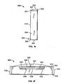
- FIG. 1 is a front elevational view of an embodiment of the dispensing system
- FIG. 2 is a rear elevational view of the dispensing system of FIG. 1 ;
- FIG. 3 is a rear isometric view of the dispensing system of FIG. 1 ;
- FIG. 4 is a side elevational view of the dispensing system of FIG. 1 ;
- FIG. 5 is a plan view of the dispensing system of FIG. 1 ;
- FIG. 6 is an exploded rear isometric view of the dispensing system of FIG. 1 depicting the display frame and a decorative element and a dispenser;
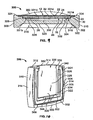
- FIG. 7 is a cross-sectional view of the dispensing system taken along the line 32-32 of FIG. 1 further including a dispenser;
- FIG. 8 is a rear isometric view of the dispensing system similar to the one depicted in FIG. 3 further including several protrusions;
- FIG. 9 is a cross-sectional view of the dispensing system taken along the lines 34-34 of FIG. 8 further including a dispenser;
- FIG. 10 is a rear isometric view of the dispensing system similar to the one depicted in FIG. 3 further including a raised bar,
- FIG. 11 is a rear isometric view of the dispensing system similar to the one depicted in FIG. 3 further including two raised bumps;
- FIG. 12 is a rear isometric view of the dispensing system similar to the one depicted in FIG. 3 further including a plurality of upraised portions;
- FIG. 13 is a rear isometric view of a different dispensing system similar to the third embodiment depicted in FIGS. 15-17 of US 2006/0000920 that further includes a stepped recess and omits the slot;
- FIG. 14 is a rear isometric view of a another embodiment of the dispensing system similar to the first embodiment depicted in FIGS. 1-7 of US 2006/0000920 and the fourth embodiment depicted in FIGS. 18-20 of US 2006/0000920 that further includes a stepped recess and omits the slot; and
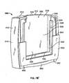
- FIG. 15 is a rear isometric view of yet another embodiment of the dispensing system, similar to the one depicted in FIG. 3 further including a dispenser and a refill holder.
- FIGS. 1-12 A volatile material dispensing system 10 embodying the present invention is depicted in FIGS. 1-12 .
- This embodiment includes a display frame 300 similar to the first embodiment shown in US 2006/000920 except that the display frame 300 does not comprise separately bonded front and rear blocks 62, 64. Rather, the display frame 300 comprises a uniform block with four substantially equal-sized side walls, a front face 302, and a rear face 304.
- the four side walls comprise a substantially planar bottom wall 306 and substantially curvilinear left, right, and top walls 308, 310, 312, respectively.
- the curvilinear left wall 308, right wall 310, and top wall 312 include a central portion 314 that extends outwardly from the display frame 300 to a greater extent than opposing ends of the respective walls 308-312.
- the left and right walls 308, 310 and the top wall 312 are angled inwardly and downwardly, respectfully, as the walls 308-312 extend from the front face 302 of the display frame 300 toward the rear face 304 thereof.
- the display frame 300 has a thickness between the front and rear faces 302, 304 within a range of about 12 mm (0.472 in.) to about 22 mm (0.866 in.), or within a range of about 15 mm (0.591 in.) to about 19 mm (0.748 in.).
- the display frame 300 may also have a height between the central portion 314 of the top wall 312 and the bottom wall 36 within a range of about 60 mm (2.362 in.) to about 110 mm (4.331 in.), or within a range of about 72 mm (2.835 in.) to about 98 mm (3.858 in.).
- the display frame 300 may have a width between the central portions 314 of the left and right walls 308, 310 within a range of about 60 mm (2.362 in.) to about 110 mm (4.331 in.), or within a range of about 72 mm (2.835 in.) to about 98 mm (3.858 in.)
- the front face 302 or front side of the display frame 300 includes a recess 316.
- FIG. 1 illustrates that the recess 316 is defined by four angled and curved side walls 318 and a bottom wall 320.
- the four side walls 318 have a shape substantially similar to the shape defined by one of the adjacent bottom, left, right, and top walls 306-312, i.e., the side wall 318 adjacent the bottom wall 306 is planar and parallel to same and each of the remaining three side walls 318 is curvilinear and parallel to one of the left, right, and top walls 308-312 adjacent thereto.
- the recess 316 is centered in the front face 302 of the display frame 300 and gives the display frame 300 the appearance of a picture frame surrounding the bottom wall 320 of the recess 316.
- the curved side walls 318 may include any number of angles and/or curves that may be symmetrical with the respective bottom, left, right, and top walls 306-312. However, other embodiments may include no recess, or multiple stepped recesses, or any other type of shaped side wall.
- a raised rib extends about an outer periphery of the front face 302 adjacent the bottom, left, right, and top walls 306-312 of the display frame 300.
- FIGS. 2, 3 , and 6 show that the rear face 304 or rear side of the display frame 300 includes a stepped recess 322 defined by stepped side walls and a square depression disposed therebetween.
- the stepped recess 322 comprises a peripheral outer recess 324 and a medial recess 326 similar to the shallow peripheral recess 52 and the deep central recess 54, respectively, of the first embodiment of US 2006/0000920 .
- the stepped recess 322 also includes an inner recess 328.
- the peripheral outer recess 324 is configured and dimensioned to receive the support flange 20 of the dispenser 12.
- the medial recess 326 and the outer peripheral recess 324 combined have a negative shape that is the same as that of the dispenser 12.
- the medial recess 326 and the outer peripheral recess 324 may have a combined shape similar to that of any other volatile material holder that is to be positioned within the display frame 300.
- the dispenser 12 is completely received within the medial recess 326 and the peripheral outer recess 324 so that the permeable membrane 24 surface is substantially flush with the rear face 304 and the flange 20 rests upon the stepped side walls defining the peripheral outer recess 324.
- the flange 20 is adhered to the stepped side walls defining the peripheral outer recess 324 in a similar manner as described herein with respect to the other embodiments.
- the medial recess 326 is configured and dimensioned to receive the cup-shaped structure 26 of the dispenser 12. As may be seen in FIGS. 6 and 7 , the medial recess 326 is deeper than the peripheral outer recess 324 since it accommodates the greater combined thickness of the cup-shaped structure 26, the flange 20, and the permeable membrane 24. Peripheral portions of the bottom wall 28 of the dispenser 12 are adjacent to and in contact or slightly spaced from the stepped side walls defining the medial recess. 326. The bottom wall 28 of the dispenser 12 is also spaced from a bottom surface 330 of the stepped recess 322 by the inner recess 328.
- FIGS. 8 and 9 depict an alternative embodiment of the display frame 300 where peripheral portions of the bottom wall 28 of the dispenser 12 are spaced from the stepped side walls of the medial recess 326.
- one or more spaced curved protrusions 331 are provided on the stepped side walls, of the medial recess 326.
- the protrusions 331 fill a gap between the bottom wall 28 and the walls defining the medial recess 326.
- the protrusions 331 prevent the dispenser 12 from bending excessively or from breaking or becoming unattached to the display frame 300 when excessive force is exerted onto the dispenser 12. Excessive force may be a particular factor during the manufacturing process when the dispenser 12 is attached to the rear face 304 of the display frame 300.
- the protrusions 331 may also provide enhanced decorative element retaining means by preventing vertical and/or lateral movement of the decorative element 14 from the confines of the inner recess 328, which will be described in further detail below.
- FIGS. 6 and 7 illustrate that the inner recess 328 is configured and dimensioned to hold and/or display a decorative element 14 such as a photograph, a picture, and/or a drawing, to name a few.
- the inner recess 328 is substantially square and is defined by the bottom surface 330 and three equal sized walls comprising a bottom wall 332, and two side walls 334.
- FIGS. 2, 3 , and 6 depict a top end of the inner recess that is open and coextensive with a channel 336 or slot.
- the channel 336 includes a bottom surface 338 that is planar with the bottom surface 330 of the inner recess 328 and two side channel walls 340 spaced from one another a similar distance as the opposing side walls 334 of the inner recess 328.
- the side channel walls 340 comprise a varying thickness as the channel extends from the top end of the of the inner recess 328 toward the top wall 312, i.e., the side channel walls 340 extend upwardly from the bottom surface 338 of the channel 336 a distance commensurate with the respective stepped side walls defining the medial and peripheral outer recesses 326, 324.
- the channel 336 extends through a portion of the top wall 312 and has an open end 342.
- the channel 336 provides a user with means to insert the decorative element 14 into the inner recess 328 when the dispenser 12 is affixed to the rear face 304 of the display frame 300.
- a user first holds the decorative element 14, such as a photograph, above the channel 336 so that a viewing surface of the decorative element 14 is positioned toward the front face 302 of the display frame 300.
- the decorative element 14 is slid or otherwise inserted into the channel 336 between the bottom surface 338 of the channel 336 and the dispenser 12.
- the decorative element 14 thereafter is disposed partially or wholly within the inner recess 328.
- peripheral portions of the bottom wall 28 of the dispenser 12 are spaced from the stepped side walls defining the medial recess 326, thereby creating a gap.
- the decorative element 14 may slip or be otherwise moved from the inner recess 328 in a lateral (toward the left or right walls 308, 310, respectively, of the display frame 300) and/or in a longitudinal manner (toward the top or bottom walls 312, 306, respectively, of the display frame 300) and be offset into the gap.
- the protrusions 331 described in connection with FIGS. 8 and 9 , and the intended variations thereof, provide a further functional characteristic by preventing longitudinal and/or lateral movement of the decorative element 14 from within the confines of the inner recess 328.
- FIG. 10 depicts an alternative embodiment for preventing longitudinal movement of the decorative element 14 in a direction toward the bottom wall 306.
- a raised bar 344 is provided on a portion of the side wall defining the medial recess 326 adjacent the bottom wall 332 of the inner recess 328.
- the raised bar 344 fills the gap between the bottom wall 28 of the dispenser 12 and the side wall of the medial recess 326 to prevent the decorative element 14 from sliding downwardly and out of the inner recess 328.
- FIG. 11 depicts an embodiment similar to the one depicted in FIG 10 , except that the raised bar 344 is replaced by two raised bumps 346a, 346b to similarly prevent movement of the decorative element 14 into the gap between the bottom wall 28 and side walls defining the medial recess 326.
- a plurality of upraised portions 348 is disposed on the side walls defining the medial recess 326 in a wave-like pattern.
- the upraised portions 348 are positioned to prevent lateral and/or longitudinal movement of the decorative element 14 from within the inner recess 328.
- Various structures with different geometric shapes are envisioned to be used in connection with the present embodiments, insofar as the structures assist in substantially preventing the decorative element 14 from moving out of the inner recess 328 and into portions of the medial recess 326.
- any number of geometric structures positioned adjacent the bottom, left, right, or top walls 306-312 may be used.
- the geometric structures may provide the same functional characteristics as the protrusions 331 described above or may work in tandem with them.
- the spacing between the bottom surface 338 and portions of the dispenser 12 may be sized to allow for varying widths of decorative elements by, for example, adjusting the size of one or more of the stepped side walls defining the stepped recess 322, making the channel 336 shallower, and/or adjusting the size of the dispenser 12.
- the bottom surface 330 of the inner recess 328 is similarly spaced from the bottom wall 28 of the dispenser 12 and may be modified to accommodate various sized decorative elements by adjusting the sizing of the stepped recess 322, the inner recess 328, and/or the dispenser 12.
- the spacing between the bottom surface 330 and the dispenser 12 is different than the spacing between the bottom surface 338 and the dispenser 12.
- Adjusting the spacing between at least one of the bottom surfaces 330, 338 and the bottom wall 28 also provides for varying means of holding the decorative element 14 within the inner recess 328.
- the spacing between the bottom surface 330 and the bottom wall 28 is relatively narrow so that when the decorative element 14 is inserted therebetween the decorative element 14 remains stationary and held in place by frictional forces.
- the spacing similarly allows for a frictional fit that is easily disrupted by movement of the display frame 300.
- spacing is provided that is about the same or slightly larger than the width of the decorative element 14. Little or no frictional forces are therefore imparted to the decorative element 14 but the decorative element 14 still remains completely or substantially parallel to the bottom surface 330 of the inner recess 328.
- the spacing is substantially greater than the width of the decorative element 14, wherein placement of the decorative element 14 into the inner recess 328 may allow the decorative element 14 to slightly tilt or rotate therein. It is contemplated that the spacing between the bottom surface 330 and the bottom wall 28 may be adjusted for any type of decorative element, such as a photograph, picture, drawing, written document, or other aesthetic or functional types of information. Similarly, the spacing between the bottom surface 338 of the channel 336 and any portion of the dispenser 12 adjacent thereto may be adjusted if the decorative element 14 extends wholly or partially into the channel 336.
- the decorative element 14 is removed from the display frame 300 by tilting, turning, and/or rotating the display frame 300 so that the open end 342 of the channel 336 is angled from its normal operating position. Angling the open end 342 of the channel 336 allows gravitational forces to independently, or in combination with forces from a user, remove the decorative element 14 from the display frame 300 through the open end 342.
- a user may use a finger or other object to pull or grasp and remove the decorative element 14 from the display frame 300.
- the decorative element 14 is removed by pulling the dispenser 12 off of the frame 300 to expose the inner recess 328 and the decorative element 14 therein.
- the inner recess 328 is centered within the rear face 304 of the display frame 300. Centering the inner recess 328 allows the user to easily center the decorative element 14 to be disposed therein with respect to the bottom, left, right, and top walls 306-312 of the display frame 300.
- the length of the bottom and the two side walls 332, 334 of the inner recess 328 may be adjusted to accommodate various sized decorative elements. For example, the spacing between the two side walls 334 may be adjusted to be substantially equal to the width of the decorative element, thereby obviating the need to center the decorative element within the inner recess 328.
- the spacing between the two side walls 334 is adjusted to be greater than the width of the decorative element, thereby allowing a user to see the level of volatile material 32 about a periphery of the decorative element 14.
- the spacing between the bottom wall 332 and the top end of the inner recess 328 may likewise be adjusted to be substantially equal to or greater than the height of the decorative element.
- spacers (not shown) are provided that may be inserted into the inner recess 328 to position the decorative element.
- the spacers' may be made of a similar or dissimilar material as the display frame 300 and may be colored or transparent.
- the rear face 304 of the display frame 300 also includes a curved foot 350 or protrusion disposed adjacent a lower side 352 of the display frame 300.
- the lower side 352 of the display frame 300 is defined by the bottom wall 306 that rests against a support surface.
- the curved foot 350 increases the stability of the display frame 300 to prevent same from tipping over. However, should the display frame 300 be tipped over, the curved foot 350 causes the permeable membrane 34 to be spaced from the support surface so that the potential for damage to the support surface by the volatile material 32 is minimized.
- the curved foot 350 extends outwardly from the rear face 304 about 4 mm (0.158 in.) to about 7 mm (0.276 in.) at its farthest point.
- FIG. 13 depicts a display frame 400 similar to the third embodiment depicted in FIGS. 15-17 of US-2006/0000920 .
- a stepped recess 402 similar to the one depicted in FIGS. 1-7 , is provided in the rear face 40 in lieu of the slot 80.
- the stepped recess includes an outer recess 404 and an inner recess 406 to provide a space for a dispenser and a decorative element (not shown).
- a channel 408 is also provided for receipt of the decorative element.
- the frame 400 is similar to the previously depicted embodiments, the present embodiment is illustrative of the varying forms that stepped recesses and dispensers may comprise.
- FIG. 14 is similar to the first embodiment depicted in FIGS.1-7 of US 2006/0000920 and the fourth embodiment depicted in FIGS. 18-20 of US2006/0000920 with the exclusion of the slot 80.
- a stepped recess that is identical to the stepped recess 322 depicted in FIGS. 1-7 is provided within the rear face 40 of the frame 450.
- a top end 452 of the flame 450 includes a wave-like shape.
- FIG. 15 depicts a further embodiment of a display frame 500 that includes a refill holder 502 which attached to the present display frame 500.
- the present embodiment affords the user the ability to releasably insert and remove the decorative element 14 and the dispenser 12 so that one or more of the decorative element 14 and the dispenser 12 may be replaced.
- Any of the display frames 400, 450, 500 may be similarly modified as the display frame 300.
- the display frame 500 could include the protrusions 331 or upraised portions 348 to assist in retaining the decorative element 14 within the inner recess 328, particularly if the cup-shaped structure 26 and the peripheral flange 20 of the dispenser 12 are spaced wholly or partially from the medial recess 326 or peripheral recess 324, respectively.
- the channel 336 may be disposed in the bottom, left, or right wall 306-310 of the display frame 300 as opposed to the top wall 312 or the protrusions 331 could be disposed within the deep central recess 54 of the display frame 10 described in connection with FIGS. 1-25 of US2006/0000920
- the volatile material dispensing system described herein advantageously combines the functional and aesthetic characteristics of a picture frame with a fragrance dispenser. Thus, the use of one unit versus two individual units in a home or office setting may be enjoyed.
Landscapes
- Health & Medical Sciences (AREA)
- Epidemiology (AREA)
- Life Sciences & Earth Sciences (AREA)
- Animal Behavior & Ethology (AREA)
- General Health & Medical Sciences (AREA)
- Public Health (AREA)
- Veterinary Medicine (AREA)
- Packaging Of Annular Or Rod-Shaped Articles, Wearing Apparel, Cassettes, Or The Like (AREA)
- Mirrors, Picture Frames, Photograph Stands, And Related Fastening Devices (AREA)
- Packages (AREA)
- Disinfection, Sterilisation Or Deodorisation Of Air (AREA)
Abstract
Description
- The present invention generally relates to a volatile material dispenser, and more particularly, to a volatile material dispenser in combination with a picture frame.
- Volatile material dispensers have been used to provide fragrance to office or home settings. One such dispenser is an ornamental design for a combination picture frame and air freshener receptacle. The picture frame is rectangular and has a bottom wall, a top wall, and two side walls. One of the side walls has a slot. An opening extends through a front face of the receptacle. A rear face of the picture frame is provided with an apertured receptacle. The receptacle has side portions that extend outwardly from the rear face of the picture frame and inwardly toward each other. The side portions are inwardly spaced from the side walls and are connected by a planar rear portion.
- Another dispenser is an air freshener support for a car with a rectangular housing having a front panel with a rectangular opening disposed therein. A photograph is nested adjacent the opening so that peripheral edges of the photograph are adjacent inner portions of the front panel. A back cover is disposed behind the photograph so as to press and retain same between the front panel and the back cover. A rectangular pad impregnated with a fragrance is disposed adjacent the back cover.
- Yet another dispenser is an air freshener picture frame with a rectangular housing having front and rear faces, wherein the front face has a front panel with a rectangular front opening therein, and the rear face has a rear opening. A back panel is disposed within the rear face and presses against a clear sheet and artwork to keep both in place within the rear face. An air freshener material is provided within an enclosure attached to a back side of the back panel, wherein the enclosure has vents to allow diffusion of a fragrance from the material.
DocumentUS 2006/0000 920 A1 shows an air freshener picture frame having front and rear faces with a recess in the rear face of the frame. A dispenser is disposed within the recess. The dispenser includes a reservoir and a vapour permeable membrane . A slot is disposed is a side wall of the frame to hold an image.
The invention provides a display frame as defined inclaim 1 below. - According to an embodiment of the present invention, a display frame comprises a frame having front and rear faces. A stepped recess is disposed within the rear face of the frame. The stepped recess includes an outer recess, a medial recess, and an inner recess. A dispenser is disposed within the outer and medial recesses. The dispenser includes a blister and a vapor permeable membrane. A channel is disposed in a side wall of the display frame in communication with the stepped recess. The inner recess is adapted to hold a decorative element.
- According to another embodiment of the present invention, a frame for displaying a decorative element comprises a frame having a dispenser disposed in a face thereof. A channel extends from an exterior surface of the frame to a void within an interior thereof. The void is defined by a bottom wall of the dispenser directed toward the interior of the frame and recessed portions of the frame. The channel is adapted to allow for the insertion of a decorative element into the void.
- Other aspects and advantages of the present invention will become apparent upon reading the following detailed description and upon reference to the drawings in which:
-
FIG. 1 is a front elevational view of an embodiment of the dispensing system; -
FIG. 2 is a rear elevational view of the dispensing system ofFIG. 1 ; -
FIG. 3 is a rear isometric view of the dispensing system ofFIG. 1 ; -
FIG. 4 is a side elevational view of the dispensing system ofFIG. 1 ; -
FIG. 5 is a plan view of the dispensing system ofFIG. 1 ; -
FIG. 6 is an exploded rear isometric view of the dispensing system ofFIG. 1 depicting the display frame and a decorative element and a dispenser; -
FIG. 7 is a cross-sectional view of the dispensing system taken along the line 32-32 ofFIG. 1 further including a dispenser; -
FIG. 8 is a rear isometric view of the dispensing system similar to the one depicted inFIG. 3 further including several protrusions; -
FIG. 9 is a cross-sectional view of the dispensing system taken along the lines 34-34 ofFIG. 8 further including a dispenser; -
FIG. 10 is a rear isometric view of the dispensing system similar to the one depicted inFIG. 3 further including a raised bar, -
FIG. 11 is a rear isometric view of the dispensing system similar to the one depicted inFIG. 3 further including two raised bumps; -
FIG. 12 is a rear isometric view of the dispensing system similar to the one depicted inFIG. 3 further including a plurality of upraised portions; -
FIG. 13 is a rear isometric view of a different dispensing system similar to the third embodiment depicted in FIGS. 15-17 ofUS 2006/0000920 that further includes a stepped recess and omits the slot; -
FIG. 14 is a rear isometric view of a another embodiment of the dispensing system similar to the first embodiment depicted inFIGS. 1-7 ofUS 2006/0000920 and the fourth embodiment depicted in FIGS. 18-20 ofUS 2006/0000920 that further includes a stepped recess and omits the slot; and -
FIG. 15 is a rear isometric view of yet another embodiment of the dispensing system, similar to the one depicted inFIG. 3 further including a dispenser and a refill holder. - A volatile material dispensing system 10 embodying the present invention is depicted in
FIGS. 1-12 . This embodiment includes adisplay frame 300 similar to the first embodiment shown inUS 2006/000920 except that thedisplay frame 300 does not comprise separately bonded front and rear blocks 62, 64. Rather, thedisplay frame 300 comprises a uniform block with four substantially equal-sized side walls, afront face 302, and arear face 304. The four side walls comprise a substantiallyplanar bottom wall 306 and substantially curvilinear left, right, andtop walls left wall 308,right wall 310, andtop wall 312 include acentral portion 314 that extends outwardly from thedisplay frame 300 to a greater extent than opposing ends of the respective walls 308-312. Further, the left andright walls top wall 312, are angled inwardly and downwardly, respectfully, as the walls 308-312 extend from thefront face 302 of thedisplay frame 300 toward therear face 304 thereof. In one embodiment, thedisplay frame 300 has a thickness between the front andrear faces display frame 300 may also have a height between thecentral portion 314 of thetop wall 312 and thebottom wall 36 within a range of about 60 mm (2.362 in.) to about 110 mm (4.331 in.), or within a range of about 72 mm (2.835 in.) to about 98 mm (3.858 in.). Similarly, thedisplay frame 300 may have a width between thecentral portions 314 of the left andright walls - The
front face 302 or front side of thedisplay frame 300 includes arecess 316.FIG. 1 illustrates that therecess 316 is defined by four angled andcurved side walls 318 and abottom wall 320. The fourside walls 318 have a shape substantially similar to the shape defined by one of the adjacent bottom, left, right, and top walls 306-312, i.e., theside wall 318 adjacent thebottom wall 306 is planar and parallel to same and each of the remaining threeside walls 318 is curvilinear and parallel to one of the left, right, and top walls 308-312 adjacent thereto. Therecess 316 is centered in thefront face 302 of thedisplay frame 300 and gives thedisplay frame 300 the appearance of a picture frame surrounding thebottom wall 320 of therecess 316. Thecurved side walls 318 may include any number of angles and/or curves that may be symmetrical with the respective bottom, left, right, and top walls 306-312. However, other embodiments may include no recess, or multiple stepped recesses, or any other type of shaped side wall. In one embodiment, a raised rib extends about an outer periphery of thefront face 302 adjacent the bottom, left, right, and top walls 306-312 of thedisplay frame 300. -
FIGS. 2, 3 , and6 show that therear face 304 or rear side of thedisplay frame 300 includes a steppedrecess 322 defined by stepped side walls and a square depression disposed therebetween. The steppedrecess 322 comprises a peripheralouter recess 324 and amedial recess 326 similar to the shallow peripheral recess 52 and the deep central recess 54, respectively, of the first embodiment ofUS 2006/0000920 . The steppedrecess 322 also includes aninner recess 328. - The peripheral
outer recess 324 is configured and dimensioned to receive thesupport flange 20 of thedispenser 12. Themedial recess 326 and the outerperipheral recess 324 combined have a negative shape that is the same as that of thedispenser 12. Alternatively, themedial recess 326 and the outerperipheral recess 324 may have a combined shape similar to that of any other volatile material holder that is to be positioned within thedisplay frame 300. When thedispenser 12 is inserted into the steppedrecess 322, such as is shown inFIG. 7 , thedispenser 12 is completely received within themedial recess 326 and the peripheralouter recess 324 so that thepermeable membrane 24 surface is substantially flush with therear face 304 and theflange 20 rests upon the stepped side walls defining the peripheralouter recess 324. Theflange 20 is adhered to the stepped side walls defining the peripheralouter recess 324 in a similar manner as described herein with respect to the other embodiments. - In this embodiment, the
medial recess 326 is configured and dimensioned to receive the cup-shapedstructure 26 of thedispenser 12. As may be seen inFIGS. 6 and7 , themedial recess 326 is deeper than the peripheralouter recess 324 since it accommodates the greater combined thickness of the cup-shapedstructure 26, theflange 20, and thepermeable membrane 24. Peripheral portions of thebottom wall 28 of thedispenser 12 are adjacent to and in contact or slightly spaced from the stepped side walls defining the medial recess. 326. Thebottom wall 28 of thedispenser 12 is also spaced from abottom surface 330 of the steppedrecess 322 by theinner recess 328. -
FIGS. 8 and9 depict an alternative embodiment of thedisplay frame 300 where peripheral portions of thebottom wall 28 of thedispenser 12 are spaced from the stepped side walls of themedial recess 326. In the present embodiment, one or more spaced curved protrusions 331 are provided on the stepped side walls, of themedial recess 326. The protrusions 331 fill a gap between thebottom wall 28 and the walls defining themedial recess 326. The protrusions 331 prevent thedispenser 12 from bending excessively or from breaking or becoming unattached to thedisplay frame 300 when excessive force is exerted onto thedispenser 12. Excessive force may be a particular factor during the manufacturing process when thedispenser 12 is attached to therear face 304 of thedisplay frame 300. It is intended that other types of protrusions, whether singly or when one of a plurality, be considered within the scope of the present disclosure regardless of the protrusions geometric shape. The protrusions 331 may also provide enhanced decorative element retaining means by preventing vertical and/or lateral movement of thedecorative element 14 from the confines of theinner recess 328, which will be described in further detail below. -
FIGS. 6 and7 illustrate that theinner recess 328 is configured and dimensioned to hold and/or display adecorative element 14 such as a photograph, a picture, and/or a drawing, to name a few. Theinner recess 328 is substantially square and is defined by thebottom surface 330 and three equal sized walls comprising abottom wall 332, and twoside walls 334.FIGS. 2, 3 , and6 depict a top end of the inner recess that is open and coextensive with achannel 336 or slot. Thechannel 336 includes abottom surface 338 that is planar with thebottom surface 330 of theinner recess 328 and twoside channel walls 340 spaced from one another a similar distance as the opposingside walls 334 of theinner recess 328. Theside channel walls 340 comprise a varying thickness as the channel extends from the top end of the of theinner recess 328 toward thetop wall 312, i.e., theside channel walls 340 extend upwardly from thebottom surface 338 of the channel 336 a distance commensurate with the respective stepped side walls defining the medial and peripheralouter recesses channel 336 extends through a portion of thetop wall 312 and has anopen end 342. - The
channel 336 provides a user with means to insert thedecorative element 14 into theinner recess 328 when thedispenser 12 is affixed to therear face 304 of thedisplay frame 300. A user first holds thedecorative element 14, such as a photograph, above thechannel 336 so that a viewing surface of thedecorative element 14 is positioned toward thefront face 302 of thedisplay frame 300. Thedecorative element 14 is slid or otherwise inserted into thechannel 336 between thebottom surface 338 of thechannel 336 and thedispenser 12. Thedecorative element 14 thereafter is disposed partially or wholly within theinner recess 328. - In some embodiments, as noted above, peripheral portions of the
bottom wall 28 of thedispenser 12 are spaced from the stepped side walls defining themedial recess 326, thereby creating a gap. In these embodiments, thedecorative element 14 may slip or be otherwise moved from theinner recess 328 in a lateral (toward the left orright walls bottom walls FIGS. 8 and9 , and the intended variations thereof, provide a further functional characteristic by preventing longitudinal and/or lateral movement of thedecorative element 14 from within the confines of theinner recess 328. -
FIG. 10 depicts an alternative embodiment for preventing longitudinal movement of thedecorative element 14 in a direction toward thebottom wall 306. A raisedbar 344 is provided on a portion of the side wall defining themedial recess 326 adjacent thebottom wall 332 of theinner recess 328. The raisedbar 344 fills the gap between thebottom wall 28 of thedispenser 12 and the side wall of themedial recess 326 to prevent thedecorative element 14 from sliding downwardly and out of theinner recess 328.FIG. 11 depicts an embodiment similar to the one depicted inFIG 10 , except that the raisedbar 344 is replaced by two raisedbumps decorative element 14 into the gap between thebottom wall 28 and side walls defining themedial recess 326. In yet another embodiment depicted inFIG. 12 , a plurality ofupraised portions 348 is disposed on the side walls defining themedial recess 326 in a wave-like pattern. Theupraised portions 348 are positioned to prevent lateral and/or longitudinal movement of thedecorative element 14 from within theinner recess 328. Various structures with different geometric shapes are envisioned to be used in connection with the present embodiments, insofar as the structures assist in substantially preventing thedecorative element 14 from moving out of theinner recess 328 and into portions of themedial recess 326. Further, any number of geometric structures positioned adjacent the bottom, left, right, or top walls 306-312 may be used. Still further, the geometric structures may provide the same functional characteristics as the protrusions 331 described above or may work in tandem with them. - In other embodiments of the
display frame 300, the spacing between thebottom surface 338 and portions of thedispenser 12 may be sized to allow for varying widths of decorative elements by, for example, adjusting the size of one or more of the stepped side walls defining the steppedrecess 322, making thechannel 336 shallower, and/or adjusting the size of thedispenser 12. Thebottom surface 330 of theinner recess 328 is similarly spaced from thebottom wall 28 of thedispenser 12 and may be modified to accommodate various sized decorative elements by adjusting the sizing of the steppedrecess 322, theinner recess 328, and/or thedispenser 12. In a different embodiment, the spacing between thebottom surface 330 and thedispenser 12 is different than the spacing between thebottom surface 338 and thedispenser 12. - Adjusting the spacing between at least one of the bottom surfaces 330, 338 and the
bottom wall 28 also provides for varying means of holding thedecorative element 14 within theinner recess 328. In one embodiment, the spacing between thebottom surface 330 and thebottom wall 28 is relatively narrow so that when thedecorative element 14 is inserted therebetween thedecorative element 14 remains stationary and held in place by frictional forces. In another embodiment, the spacing similarly allows for a frictional fit that is easily disrupted by movement of thedisplay frame 300. In a different embodiment, spacing is provided that is about the same or slightly larger than the width of thedecorative element 14. Little or no frictional forces are therefore imparted to thedecorative element 14 but thedecorative element 14 still remains completely or substantially parallel to thebottom surface 330 of theinner recess 328. In yet anther embodiment, the spacing is substantially greater than the width of thedecorative element 14, wherein placement of thedecorative element 14 into theinner recess 328 may allow thedecorative element 14 to slightly tilt or rotate therein. It is contemplated that the spacing between thebottom surface 330 and thebottom wall 28 may be adjusted for any type of decorative element, such as a photograph, picture, drawing, written document, or other aesthetic or functional types of information. Similarly, the spacing between thebottom surface 338 of thechannel 336 and any portion of thedispenser 12 adjacent thereto may be adjusted if thedecorative element 14 extends wholly or partially into thechannel 336. - The
decorative element 14 is removed from thedisplay frame 300 by tilting, turning, and/or rotating thedisplay frame 300 so that theopen end 342 of thechannel 336 is angled from its normal operating position. Angling theopen end 342 of thechannel 336 allows gravitational forces to independently, or in combination with forces from a user, remove thedecorative element 14 from thedisplay frame 300 through theopen end 342. In other embodiments, a user may use a finger or other object to pull or grasp and remove thedecorative element 14 from thedisplay frame 300. In yet another embodiment, thedecorative element 14 is removed by pulling thedispenser 12 off of theframe 300 to expose theinner recess 328 and thedecorative element 14 therein. - The
inner recess 328 is centered within therear face 304 of thedisplay frame 300. Centering theinner recess 328 allows the user to easily center thedecorative element 14 to be disposed therein with respect to the bottom, left, right, and top walls 306-312 of thedisplay frame 300. The length of the bottom and the twoside walls inner recess 328 may be adjusted to accommodate various sized decorative elements. For example, the spacing between the twoside walls 334 may be adjusted to be substantially equal to the width of the decorative element, thereby obviating the need to center the decorative element within theinner recess 328. In a different embodiment, the spacing between the twoside walls 334 is adjusted to be greater than the width of the decorative element, thereby allowing a user to see the level ofvolatile material 32 about a periphery of thedecorative element 14. The spacing between thebottom wall 332 and the top end of theinner recess 328 may likewise be adjusted to be substantially equal to or greater than the height of the decorative element. In a different embodiment, spacers (not shown) are provided that may be inserted into theinner recess 328 to position the decorative element. The spacers' may be made of a similar or dissimilar material as thedisplay frame 300 and may be colored or transparent. - The
rear face 304 of thedisplay frame 300 also includes acurved foot 350 or protrusion disposed adjacent alower side 352 of thedisplay frame 300. Thelower side 352 of thedisplay frame 300 is defined by thebottom wall 306 that rests against a support surface. Thecurved foot 350 increases the stability of thedisplay frame 300 to prevent same from tipping over. However, should thedisplay frame 300 be tipped over, thecurved foot 350 causes thepermeable membrane 34 to be spaced from the support surface so that the potential for damage to the support surface by thevolatile material 32 is minimized. Thecurved foot 350 extends outwardly from therear face 304 about 4 mm (0.158 in.) to about 7 mm (0.276 in.) at its farthest point. - Any of the embodiments disclosed herein may be accordingly modified in a manner known by those skilled in the art to include a channel that provides access to an inner recess adapted to hold a decorative element between walls defining the recess and a portion of a fragrance dispenser. For example,
FIG. 13 depicts adisplay frame 400 similar to the third embodiment depicted in FIGS. 15-17 ofUS-2006/0000920 . However, a steppedrecess 402, similar to the one depicted inFIGS. 1-7 , is provided in therear face 40 in lieu of the slot 80. The stepped recess includes anouter recess 404 and aninner recess 406 to provide a space for a dispenser and a decorative element (not shown). Achannel 408 is also provided for receipt of the decorative element. While theframe 400 is similar to the previously depicted embodiments, the present embodiment is illustrative of the varying forms that stepped recesses and dispensers may comprise. Yet another embodiment of adisplay frame 450 is shown inFIG. 14 , which is similar to the first embodiment depicted inFIGS.1-7 ofUS 2006/0000920 and the fourth embodiment depicted in FIGS. 18-20 ofUS2006/0000920 with the exclusion of the slot 80. A stepped recess that is identical to the steppedrecess 322 depicted inFIGS. 1-7 is provided within therear face 40 of theframe 450. Atop end 452 of theflame 450 includes a wave-like shape. Further, any of the embodiments incorporated herein by reference may be similarly modified to include a channel that provides access to an inner recess adapted to hold a decorative element between walls defining the recess and a portion of a fragrance dispenser. For exampleFIG. 15 depicts a further embodiment of adisplay frame 500 that includes arefill holder 502 which attached to thepresent display frame 500. The present embodiment affords the user the ability to releasably insert and remove thedecorative element 14 and thedispenser 12 so that one or more of thedecorative element 14 and thedispenser 12 may be replaced. Any of the display frames 400, 450, 500 may be similarly modified as thedisplay frame 300. For example, thedisplay frame 500 could include the protrusions 331 orupraised portions 348 to assist in retaining thedecorative element 14 within theinner recess 328, particularly if the cup-shapedstructure 26 and theperipheral flange 20 of thedispenser 12 are spaced wholly or partially from themedial recess 326 orperipheral recess 324, respectively. - It is intended that various modifications to the structure described herein be considered within the scope of the present disclosure. Further, it is intended that the disclosure presented in connection with the arrangements depicted in
FIGS. 1-15 may be used to modify the embodiments described in connection with FIGS. 1-25 ofUS2006/0000920 and vice versa. For example, thechannel 336 may be disposed in the bottom, left, or right wall 306-310 of thedisplay frame 300 as opposed to thetop wall 312 or the protrusions 331 could be disposed within the deep central recess 54 of the display frame 10 described in connection with FIGS. 1-25 ofUS2006/0000920 - The volatile material dispensing system described herein advantageously combines the functional and aesthetic characteristics of a picture frame with a fragrance dispenser. Thus, the use of one unit versus two individual units in a home or office setting may be enjoyed.
- Numerous modifications will be apparent to those skilled in the art in view of the foregoing description. Accordingly, this description is to be construed as illustrative only and is presented for the purpose of enabling those skilled in the art to make and use the invention and to teach the best mode of carrying out same. The exclusive rights to all modifications which come within the scope of the appended claims are reserved.
Claims (8)
- A display frame (300) comprising:a frame having front and rear faces (302, 304);a stepped recess (322) disposed within the rear face (304) of the frame, wherein the stepped recess (322) includes an outer recess (324), a medial recess (326) and an inner recess (328);a dispenser (12) disposed within the outer and medial recesses (324, 326), the dispenser including a vapor permeable membrane (24); anda channel (336) disposed in a side wall (334) of the display frame in communication with the stepped recess (322),
wherein the inner recess (328) is adapted to hold a decorative element (14). - The display frame of claim 1, wherein the dispenser includes a flange (20) extending about a periphery of a blister (18), and wherein the flange (20) is disposed within the outer recess (324) and the blister (18) is disposed within the medial recess (326).
- The display frame of claim 2, wherein a bottom wall (28) of the blister (18) is spaced from a bottom surface of the inner recess (328).
- The display frame of claim 3, wherein peripheral portions of the bottom wall (28) are spaced from side walls of the medial recess (326).
- The display frame of claim 4, wherein at least one protrusion (331) is disposed on the side walls of the medial recess (326).
- The display frame of claim 1 further comprising means for preventing at least one of lateral and longitudinal movement of the decorative element (14).
- The display frame of claim 1, wherein the inner recess (328) is substantially square and defined by a bottom surface, a bottom wall, two side walls, and an open top end.
- The display frame of claim 7, wherein a first end of the decorative element (14) rests upon the bottom wall of the inner recess (328).
Applications Claiming Priority (2)
| Application Number | Priority Date | Filing Date | Title |
|---|---|---|---|
| US11/395,357 US7441360B2 (en) | 2004-06-30 | 2006-03-31 | Air freshener with picture frame |
| PCT/US2007/008035 WO2007117388A1 (en) | 2006-03-31 | 2007-03-30 | Air freshener with picture frame |
Publications (2)
| Publication Number | Publication Date |
|---|---|
| EP2004024A1 EP2004024A1 (en) | 2008-12-24 |
| EP2004024B1 true EP2004024B1 (en) | 2009-11-25 |
Family
ID=38255418
Family Applications (1)
| Application Number | Title | Priority Date | Filing Date |
|---|---|---|---|
| EP07754545A Not-in-force EP2004024B1 (en) | 2006-03-31 | 2007-03-30 | Air freshener with picture frame |
Country Status (13)
| Country | Link |
|---|---|
| US (1) | US7441360B2 (en) |
| EP (1) | EP2004024B1 (en) |
| JP (1) | JP2009532100A (en) |
| KR (1) | KR101391722B1 (en) |
| CN (1) | CN101442925B (en) |
| AT (1) | ATE449551T1 (en) |
| AU (1) | AU2007235565B2 (en) |
| BR (1) | BRPI0709670A2 (en) |
| CA (1) | CA2647228A1 (en) |
| DE (1) | DE602007003458D1 (en) |
| ES (1) | ES2336718T3 (en) |
| MX (1) | MX2008012605A (en) |
| WO (1) | WO2007117388A1 (en) |
Cited By (1)
| Publication number | Priority date | Publication date | Assignee | Title |
|---|---|---|---|---|
| US11944096B2 (en) | 2019-12-06 | 2024-04-02 | S.C. Johnson & Son, Inc. | Dispenser and method of use thereof |
Families Citing this family (52)
| Publication number | Priority date | Publication date | Assignee | Title |
|---|---|---|---|---|
| US7687037B2 (en) | 2003-02-28 | 2010-03-30 | American Covers, Inc. | Air freshener and method |
| US8460609B1 (en) | 2003-02-28 | 2013-06-11 | American Covers, Inc. | Vent stick air freshener with grip head |
| US8685330B2 (en) | 2005-10-31 | 2014-04-01 | American Covers, Inc. | Air freshener flower with vent stick |
| US7940518B2 (en) * | 2007-04-03 | 2011-05-10 | Pandigital, Inc. | Dual frame electronic display |
| RU2360589C1 (en) * | 2008-01-14 | 2009-07-10 | Александр Иванович Максимов | Manufacturing method of support for photo and support for photo |
| US8641000B1 (en) * | 2008-09-10 | 2014-02-04 | Frances W. Eide | Tile holder and methods of use |
| US9453652B2 (en) | 2009-01-09 | 2016-09-27 | S. C. Johnson & Son, Inc. | Fragrance dispenser |
| US8851396B2 (en) | 2009-01-27 | 2014-10-07 | American Covers, Inc. | Dual scent air freshener with manual combiner |
| USD597644S1 (en) * | 2009-02-11 | 2009-08-04 | Aromate Industries Co., Ltd. | Air freshener device |
| USD606185S1 (en) * | 2009-06-10 | 2009-12-15 | S.C. Johnson & Son, Inc. | Air freshener |
| MX2012003412A (en) | 2009-09-21 | 2012-04-30 | Johnson & Son Inc S C | Methods of emitting a volatile material from a diffuser. |
| US8097215B2 (en) * | 2009-10-17 | 2012-01-17 | Hui-Chin Chen | Wall-mounted aromatic air freshener device |
| US20110146125A1 (en) * | 2009-12-21 | 2011-06-23 | Orme-Johnson Nathan P | Picture frame assembly |
| US8485454B1 (en) | 2009-12-30 | 2013-07-16 | American Covers, Inc. | Rotatable and adjustable air freshener |
| USD669569S1 (en) | 2010-09-08 | 2012-10-23 | S. C. Johnson & Son, Inc. | Volatile active diffuser |
| USD667308S1 (en) | 2010-09-08 | 2012-09-18 | S.C. Johnson & Son, Inc. | Refill container |
| US9717814B2 (en) * | 2010-10-01 | 2017-08-01 | S. C. Johnson & Son, Inc. | Dispensing device |
| US8673223B1 (en) | 2010-10-29 | 2014-03-18 | American Covers, Inc. | Fan powered air freshener automobile visor clip |
| US8662480B1 (en) | 2010-10-29 | 2014-03-04 | American Covers, Inc. | Fan powered air freshener automobile power outlet |
| US8490846B1 (en) | 2011-01-10 | 2013-07-23 | American Covers, Inc. | Frictional holding pad with inclined grip |
| CA143436S (en) * | 2011-06-20 | 2012-06-21 | Reckitt & Colman Overseas | Refill for an air freshener device |
| CA143435S (en) * | 2011-06-20 | 2012-06-21 | Reckitt & Colman Overseas | Air freshener device |
| CA143434S (en) * | 2011-06-20 | 2012-06-21 | Reckitt & Colman (Overseas) Limited | Air freshener device |
| JP6100253B2 (en) * | 2011-07-22 | 2017-03-22 | ゾベーレ ホールディング ソチエタ ペル アツィオーニ | Equipment for evaporation of volatile substances |
| KR101239467B1 (en) | 2011-09-16 | 2013-03-06 | 이영철 | The non-line plastic injection fame with the bezel |
| US9155811B1 (en) | 2011-12-02 | 2015-10-13 | American Covers, Inc. | Packaged vent stick air freshener with custom head |
| US9144621B1 (en) | 2012-01-10 | 2015-09-29 | American Covers, Inc. | Air freshener canister with pull top |
| US8730024B1 (en) * | 2012-03-08 | 2014-05-20 | Carlos H. Cabezas | Universal removable fuel tank indicator |
| US9248210B2 (en) * | 2012-08-15 | 2016-02-02 | S.C. Johnson & Son, Inc. | Dual purpose cartridge dispensing system |
| US9204741B2 (en) | 2012-08-15 | 2015-12-08 | S.C. Johnson & Son, Inc. | Cartridge holder |
| GB201216521D0 (en) * | 2012-09-17 | 2012-10-31 | Reckitt & Colman Overseas | Assembley for modifying the ambiance of a local environment |
| KR101310120B1 (en) | 2012-09-28 | 2013-09-24 | 김상운 | Frame having main screen and sub screen with covering function |
| USD689181S1 (en) | 2012-10-23 | 2013-09-03 | American Covers, Inc. | Air freshener container |
| US9138502B2 (en) | 2012-10-23 | 2015-09-22 | American Covers, Inc. | Air freshener with decorative insert |
| US9042712B2 (en) | 2012-10-23 | 2015-05-26 | American Covers, Inc. | Heated air freshener for 12V receptacle |
| USD684675S1 (en) | 2012-10-23 | 2013-06-18 | American Covers, Inc. | Dual axis vent rod air freshener |
| US9399080B2 (en) | 2012-10-23 | 2016-07-26 | American Covers, Inc. | Heated air freshener with power port for 12v receptacle |
| US9278151B2 (en) | 2012-11-27 | 2016-03-08 | S.C. Johnson & Son, Inc. | Volatile material dispenser |
| US9327043B2 (en) * | 2013-01-25 | 2016-05-03 | The Procter & Gamble Company | Device for delivering a volatile fluid to the atmosphere |
| USD711521S1 (en) | 2013-04-15 | 2014-08-19 | American Covers, Inc. | Skull on dog tag shaped air freshener |
| AU2014204416B2 (en) | 2013-07-22 | 2017-09-07 | Ge Global Sourcing Llc | System and method for monitoring braking effort |
| ES2545833B1 (en) * | 2014-02-12 | 2016-06-22 | Zobele España, S.A. | Evaporator of volatile substances |
| USD751828S1 (en) * | 2014-11-14 | 2016-03-22 | Hallmark Cards, Incorporated | Picture frame |
| WO2016149451A1 (en) * | 2015-03-19 | 2016-09-22 | S. C. Johnson & Son, Inc. | Composite membrane |
| US11077221B2 (en) * | 2016-01-25 | 2021-08-03 | S. C. Johnson & Son, Inc. | Volatile dispenser for use in volatile dispensing systems |
| US10994042B2 (en) | 2016-01-25 | 2021-05-04 | S. C. Johnson & Son, Inc. | Heated air freshener |
| US10940226B2 (en) | 2016-03-01 | 2021-03-09 | S. C. Johnson & Son, Inc. | Dispenser |
| KR200483943Y1 (en) * | 2016-03-31 | 2017-07-11 | 김필원 | Skin Frames |
| US11006788B2 (en) * | 2016-11-11 | 2021-05-18 | Trevor Thomas | Product dispenser with active media display |
| USD980632S1 (en) | 2019-06-25 | 2023-03-14 | Lester Smith | AC vent attached picture frame |
| USD1003611S1 (en) * | 2021-09-19 | 2023-11-07 | Klix.Co.Il Ltd. | Frame for pictures or mirrors |
| NL2029229B1 (en) * | 2021-09-23 | 2023-03-30 | Ksp Holding B V | Dispensing system for dispensing a fluid into the atmosphere |
Family Cites Families (230)
| Publication number | Priority date | Publication date | Assignee | Title |
|---|---|---|---|---|
| US886840A (en) * | 1907-03-11 | 1908-05-05 | Mueller Brothers Art And Mfg Company | Frame. |
| US882710A (en) * | 1907-04-03 | 1908-03-24 | George Frank E Pearsall | Border for pictures. |
| US1068621A (en) | 1911-08-29 | 1913-07-29 | Adolph Abraham | Interchangeable-picture frame. |
| US1204934A (en) * | 1915-12-02 | 1916-11-14 | William Larke Burford | Advertising medium. |
| US1261133A (en) * | 1917-10-09 | 1918-04-02 | William George Kidd | Mount for use in photograph-frames. |
| US1802999A (en) * | 1930-02-04 | 1931-04-28 | Friedman Silver Co Inc | Picture-frame panel |
| US1815841A (en) * | 1930-07-12 | 1931-07-21 | Gastgivar Otto Torsten | Picture frame |
| US1940328A (en) | 1932-08-08 | 1933-12-19 | Schrotenboer Benjamin | Box picture frame |
| US2268529A (en) * | 1938-11-21 | 1941-12-30 | Alfred H Stiles | Picture mounting means |
| US2469656A (en) * | 1946-04-19 | 1949-05-10 | Peter H Lienert | Vaporizer |
| US2550954A (en) | 1947-03-17 | 1951-05-01 | Marie Isadora Malone | Combination sheet-containing frame and beneficiating reagent receptacle |
| US2579715A (en) | 1947-10-10 | 1951-12-25 | Puro Co Inc | Moth repellent and deodorant container |
| US2577320A (en) | 1948-03-23 | 1951-12-04 | Fenyo Julius | Perfume containing painting |
| US2779624A (en) | 1955-06-21 | 1957-01-29 | Plymouth Products Co | Self-deodorizing ash tray |
| US2840689A (en) | 1957-03-15 | 1958-06-24 | Sylvin M Kazor | Heat-rotated illuminated ornaments |
| US3178844A (en) | 1963-05-06 | 1965-04-20 | Fay F Christian | Illusion type picture mounting |
| US3424380A (en) * | 1967-06-13 | 1969-01-28 | Frank J Curran Co | Package and support therefor |
| US3540146A (en) * | 1968-06-11 | 1970-11-17 | Robert M Watkins | Easel-back frame and adaptor therefor |
| US3558055A (en) | 1968-10-15 | 1971-01-26 | Alloys Res & Mfg Corp | Space deodorizer and the like |
| US3570160A (en) | 1969-02-17 | 1971-03-16 | Intercraft Ind Corp | Wide width metal photo frame and molding strip |
| US4101720A (en) | 1972-03-01 | 1978-07-18 | Owens-Illinois, Inc. | Degradable plastic |
| US3741711A (en) | 1972-03-27 | 1973-06-26 | G Bryant | Composite indefinitely reusable decorative candle |
| US3790081A (en) | 1972-06-26 | 1974-02-05 | Johnson & Son Inc S C | Vapor dispensing device |
| US3822495A (en) | 1972-11-28 | 1974-07-09 | Happy Shokai Co Ltd | Improved photograph mount |
| US3804330A (en) | 1973-01-15 | 1974-04-16 | Shell Oil Co | Vapor releasing device |
| US3948445A (en) | 1973-06-26 | 1976-04-06 | Andeweg Frits J | Material vapor generator with heat accelerated vapor release |
| US4009384A (en) | 1975-03-10 | 1977-02-22 | The Raymond Lee Organization, Inc. | Lamp scent unit |
| USD247573S (en) * | 1975-10-21 | 1978-03-21 | Globol-Werk Gmbh | Assembly for the evaporation of an active volatile substance |
| USD243402S (en) * | 1976-03-23 | 1977-02-15 | Irving Leonard A | Air freshener housing |
| US4158440A (en) | 1976-10-12 | 1979-06-19 | The Ridson Manufacturing Company | Device for releasing a volatile substance in a controlled manner |
| US4184099A (en) | 1977-04-27 | 1980-01-15 | International Flavors & Fragrances Inc. | Composition for slow release of volatile ingredients at _high temperature; and article comprising same |
| US4285468A (en) | 1977-06-03 | 1981-08-25 | Sy Hyman | Article for the dispensing of volatiles |
| US4161283A (en) | 1977-06-03 | 1979-07-17 | Sy Hyman | Article for the dispensing of volatiles |
| US4157787A (en) | 1977-08-23 | 1979-06-12 | Milpak Incorporated | Air freshener dispenser |
| US4165573A (en) | 1978-02-06 | 1979-08-28 | Richards Marjorie S | Coin holder |
| US4173604A (en) | 1978-02-09 | 1979-11-06 | Cline-Buckner, Inc. | Environmental control dispenser |
| US4170080A (en) | 1978-03-09 | 1979-10-09 | Bergh Bros. Co., Inc. | Expanded composite picture frame |
| USD260503S (en) | 1978-08-23 | 1981-09-01 | Stangarone Nickolas G | Illuminated display |
| USD263334S (en) * | 1979-03-23 | 1982-03-09 | Globol-Werk Gmbh | Air freshener |
| US4314915A (en) | 1979-08-03 | 1982-02-09 | International Flavors & Fragrances Inc. | Uses in perfumery of ether derivatives of indanes |
| US4293095A (en) | 1979-11-09 | 1981-10-06 | The Procter & Gamble Company | Air treating device |
| US4327056A (en) | 1980-10-09 | 1982-04-27 | Gaiser Conrad J | Deodorant dispenser |
| JPS57102813A (en) | 1980-12-17 | 1982-06-26 | Takasago Corp | Perfume composition |
| EP0056109B1 (en) | 1981-01-13 | 1986-01-15 | Firmenich Sa | Use of 2,6,6-trimethyl-cyclohex-2-ene-1-yl-carboxylic-acid methyl ester as a perfuming agent |
| USD269838S (en) | 1981-03-20 | 1983-07-26 | New Hermes Incorporated | Picture frame |
| US4476171A (en) | 1982-02-22 | 1984-10-09 | Hakugen Co., Ltd. | Fragrance releasing articles |
| USD271359S (en) * | 1982-03-22 | 1983-11-15 | Walter Le | Picture frame |
| USD275700S (en) * | 1982-05-18 | 1984-09-25 | The Drackett Company | Air freshener |
| USD275223S (en) * | 1982-05-18 | 1984-08-21 | The Drackett Company | Air freshener |
| CH662736A5 (en) | 1983-01-14 | 1987-10-30 | Firmenich & Cie | DEVICE FOR SCENTING AMBIENT AIR AND CLOSED ENCLOSURES. |
| US4781895A (en) | 1983-03-21 | 1988-11-01 | Donald Spector | Candle-powered aroma generator |
| USD279146S (en) * | 1983-07-22 | 1985-06-11 | Mccaffrey James A | Picture frame |
| US4580581A (en) | 1984-03-12 | 1986-04-08 | Reece Everett E | Self deodorizing ash tray |
| US4493011A (en) | 1984-03-14 | 1985-01-08 | Donald Spector | Aroma disc for table lamp |
| US4695435A (en) | 1984-03-23 | 1987-09-22 | Donald Spector | Light-activated aroma generator |
| USD280363S (en) * | 1984-04-02 | 1985-09-03 | Wisecup Jr Wilbur V | Photograph display frame |
| USD288003S (en) * | 1984-10-25 | 1987-01-27 | Airwick Industries, Inc. | Housing for air freshener |
| US4549250A (en) | 1984-10-30 | 1985-10-22 | Donald Spector | Night light assembly |
| US4794714A (en) | 1985-03-07 | 1989-01-03 | Weisgerber Robert G | Frame assembly for a display item |
| EP0214918A1 (en) | 1985-08-09 | 1987-03-18 | SOCIETE INTERNATIONALE DE FABRICATION ET DE DIFFUSION DE PRODUITS PARFUMES-I.P.P. Société à responsabilité limitée | Volatile liquid fluid diffuser |
| USD296957S (en) * | 1985-09-06 | 1988-08-02 | Melannco International Ltd. | Zig-zag photograph holder |
| ZA866569B (en) | 1985-10-15 | 1987-05-27 | Union Camp Corp | Device for dispensing volatile materials |
| NL8503456A (en) | 1985-12-16 | 1987-07-16 | Naarden International Nv | TIME INDICATOR SYSTEMS, AND SUCH INDICATOR SYSTEMS CONTAINING PRODUCTS OF LIMITED USE OR LIFE. |
| US4714984A (en) | 1986-09-03 | 1987-12-22 | Donald Spector | Night light assembly |
| GB8622046D0 (en) | 1986-09-12 | 1986-10-22 | Reckitt & Colmann Prod Ltd | Emanator for volatile liquids |
| US4720409A (en) | 1986-11-20 | 1988-01-19 | Donald Spector | Film-laminate type air freshener |
| US4809912A (en) | 1987-03-27 | 1989-03-07 | Delaire, Inc. | Membrane-gel diffusion device |
| USD305703S (en) | 1987-04-15 | 1990-01-30 | Wang Thomas T M | Photograph frame mount |
| US4849606A (en) | 1987-12-23 | 1989-07-18 | S. C. Johnson & Son, Inc. | Tamper-resistant container utilizing a flexible seal |
| US4814212A (en) | 1988-05-05 | 1989-03-21 | Donald Spector | Automobile air freshener unit |
| US4874129A (en) | 1988-06-30 | 1989-10-17 | Dow Corning Corporation | Multi-laminate fragrance release device |
| US4995555A (en) | 1988-11-14 | 1991-02-26 | American Cyanamid Company | Air treatment device and method |
| US4917301A (en) | 1988-11-15 | 1990-04-17 | International Flavors & Fragrances, Inc. | Container with microporous membrane for dispensing vapor from volatile liquid |
| US4939858A (en) | 1989-01-06 | 1990-07-10 | Dailey Michael P | Picture frame |
| US4883692A (en) | 1989-01-13 | 1989-11-28 | Donald Spector | Aromatic foam-plastic decorative object |
| USD320266S (en) * | 1989-01-23 | 1991-09-24 | Waterbury Companies Inc. | Air fragrance dispenser |
| US4959087A (en) | 1989-06-14 | 1990-09-25 | James Kappernaros | Air conditioning system filter with variable rate scent release |
| GB2236677A (en) | 1989-08-26 | 1991-04-17 | Reckitt & Colmann Prod Ltd | Device for the evaporation of volatile liquids |
| US4993177A (en) | 1989-10-10 | 1991-02-19 | Hudson Teresa L | Air freshener support |
| USD325077S (en) * | 1990-04-03 | 1992-03-31 | Neutron Industries, Inc. | Portable air freshener container |
| US5060858A (en) | 1990-05-14 | 1991-10-29 | Wessel Fragrances, Inc. | Method and apparatus for dispensing volatile components of an air treating gel |
| USD346068S (en) * | 1990-08-14 | 1994-04-19 | Henredon Furniture Industries, Inc. | Mirror |
| EP0489269B1 (en) | 1990-12-05 | 1995-09-13 | Firmenich Sa | Plastic package with multiple compartments for liquid and solid products |
| US5163616A (en) | 1991-01-14 | 1992-11-17 | Block Drug Company, Inc. | Air freshener device with visual signal means |
| US5165603A (en) | 1991-03-08 | 1992-11-24 | Hahn Gary S | Fragrance-emitting container |
| US5148984A (en) | 1991-03-14 | 1992-09-22 | Vaportek, Inc. | Device for dispensing a vaporizable material |
| US5230867A (en) | 1991-04-05 | 1993-07-27 | Waterbury Companies, Inc. | Extended release fragrance dispensing cartridge |
| GB9109442D0 (en) | 1991-05-01 | 1991-06-26 | Volex Group Plc | Apparatus for emitting a chemical agent |
| USD339238S (en) * | 1991-08-12 | 1993-09-14 | Lawrence Hamilton | Picture frame |
| US5148983A (en) | 1991-08-16 | 1992-09-22 | Ralph Muniz | Scented souvenir card |
| USD339242S (en) | 1991-10-11 | 1993-09-14 | Sontag Ronald E | Swiveling picture frame |
| US5247745A (en) | 1992-05-11 | 1993-09-28 | Theresa Valentino | Illuminated picture frame apparatus |
| JPH0593321U (en) * | 1992-05-15 | 1993-12-21 | 秀雄 栗田 | Picture frame |
| US5259555A (en) | 1992-07-27 | 1993-11-09 | Kiefer Bruce C | Wooden air freshener with fragrance loading chamber |
| US5304358A (en) | 1992-08-31 | 1994-04-19 | Ralph Muniz | Air freshener device |
| GB9219999D0 (en) | 1992-09-22 | 1992-11-04 | Reckitt & Colmann Prod Ltd | Preparation of a medicament |
| US5367802A (en) | 1993-03-16 | 1994-11-29 | Rosenberg; Harry | Picture frame |
| US5334361A (en) | 1993-03-22 | 1994-08-02 | Anthony Rafaelides | Car air freshener |
| US5503332A (en) | 1993-05-03 | 1996-04-02 | Glenn; Susa | Scent packet and method of making scent packet |
| US5439100A (en) | 1993-05-04 | 1995-08-08 | The Dial Corp. | Packaging system for dispensing cartridge for volatiles |
| US5395047A (en) | 1993-05-24 | 1995-03-07 | Minnesota Mining And Manufacturing Company | Repositionable device for delivery of volatile materials |
| USD358037S (en) | 1993-08-05 | 1995-05-09 | Monroe Kurt R | Picture frame |
| FR2710495B1 (en) | 1993-09-28 | 1995-10-27 | Celaflor Gmbh | Device for carrying out insecticide treatments, and their use in dwellings. |
| US5711955A (en) | 1993-09-28 | 1998-01-27 | Celaflor Gmbh | Insect combatant controlled/prolonged delivery device |
| USD354627S (en) | 1993-11-16 | 1995-01-24 | Umbra U.S.A. Inc. | Picture frame |
| US5782409A (en) | 1993-12-06 | 1998-07-21 | Paul; Leonard | Air freshening and deodorizing system |
| US5361522A (en) * | 1994-01-28 | 1994-11-08 | Green Dennis E | Air freshener picture frame |
| USD361896S (en) * | 1994-02-23 | 1995-09-05 | Andley Corp. | Quick mount photograph and negative frame |
| US5462006A (en) | 1994-03-11 | 1995-10-31 | Thiruppathi; Devaraj | Bookmark |
| US6065687A (en) | 1994-05-24 | 2000-05-23 | Shin-Etsu Chemical Co., Ltd. | Sustained release preparations |
| US5637401A (en) | 1994-06-08 | 1997-06-10 | Fragrance Technology Trust | Odorant composition, delivery system and method |
| USD360461S (en) * | 1994-08-02 | 1995-07-18 | Odorite International, Inc. | Portable air freshener |
| USD369473S (en) * | 1994-09-08 | 1996-05-07 | Laservision Productions, Inc. | Display frame |
| US5529243A (en) | 1995-01-11 | 1996-06-25 | Product Innovation Resource, Inc. | Scent dispenser |
| AU126256S (en) * | 1995-02-07 | 1996-03-25 | Reckitt Benckiser Uk Ltd | Container for air freshener |
| USD366707S (en) * | 1995-02-21 | 1996-01-30 | Black & Decker Inc. | Flexible flashlight |
| JPH08241039A (en) | 1995-03-02 | 1996-09-17 | Dainippon Printing Co Ltd | A sticker that gives off a scent when peeled off |
| USD366107S (en) * | 1995-04-18 | 1996-01-09 | Kevin Lamont Shaffer | Combination picture frame and air freshener receptacle |
| US5647052A (en) | 1995-04-28 | 1997-07-08 | Reckitt & Colman Inc. | Volatile substance dispenser and method of dispensing a volatile substance with dissipation indication |
| US6358577B1 (en) | 1995-06-07 | 2002-03-19 | Pechiney Emballage Flexible Europe | Membrane permeable to aromatic products |
| USD374777S (en) | 1995-06-07 | 1996-10-22 | Yaacov Agam | Picture frame |
| US5804264A (en) | 1995-06-07 | 1998-09-08 | American National Can Company | Membrane permeable to frangrances and other products |
| US5556192A (en) * | 1995-07-18 | 1996-09-17 | Yeti Shine Co., Ltd. | Perfumer structure with an optically controlled night lamp |
| US5735460A (en) | 1995-09-05 | 1998-04-07 | United Industrial Trading Corp. | Air freshener housing cover |
| USD372797S (en) | 1995-09-07 | 1996-08-20 | Tropar Manufacturing Company, Inc. | Frame |
| JPH0984863A (en) | 1995-09-26 | 1997-03-31 | Yukitaka Nishimoto | Aromatic container |
| USD376914S (en) | 1995-12-14 | 1996-12-31 | Waszkiewicz Iii John C | Mirrored picture frame |
| GB9525954D0 (en) | 1995-12-19 | 1996-02-21 | Johnson & Son Inc S C | Device for dispensing volatile material |
| US5651942A (en) | 1996-01-11 | 1997-07-29 | Christensen; Arthur E. | Aromatic fragrance generator |
| USD380822S (en) * | 1996-04-17 | 1997-07-08 | Ecolab Inc. | Air freshener cartridge |
| US5845847A (en) | 1996-05-14 | 1998-12-08 | S. C. Johnson & Son, Inc. | Air freshener dispenser device |
| USD383613S (en) * | 1996-05-20 | 1997-09-16 | M & R Pictures U.S.A., Inc. | Picture display |
| US5899382A (en) | 1996-05-24 | 1999-05-04 | Woodco Manufacturing, Inc. | Air freshener |
| US5788155A (en) | 1996-06-28 | 1998-08-04 | S. C. Johnson & Son, Inc. | Air freshener dispenser device with dual cartridge capacity |
| US5679334A (en) | 1996-08-14 | 1997-10-21 | Bath & Body Works, Inc. | Gel air freshener and method of making the same |
| USD384821S (en) | 1996-08-19 | 1997-10-14 | David Sugar | Combination humidor/picture frame |
| US5950922A (en) * | 1996-09-13 | 1999-09-14 | Flinn; Gregory | Holder for an air freshener |
| US5744106A (en) | 1996-10-15 | 1998-04-28 | Eagle; Richard E. | Heated scent dispenser |
| GB9622354D0 (en) | 1996-10-28 | 1997-01-08 | Culmstock Ltd | Method and apparatus incorporating air modifying agents |
| US5749519A (en) | 1996-12-13 | 1998-05-12 | S. C. Johnson & Son, Inc. | Liquid air freshener dispenser device with nonporous wicking means |
| US5749520A (en) | 1996-12-18 | 1998-05-12 | S. C. Johnson & Son, Inc. | Liquid air freshener dispenser device with capillary wicking means |
| USD392031S (en) | 1997-01-17 | 1998-03-10 | Miller Wendy B | Air duct filter apparatus |
| FR2760194B1 (en) | 1997-02-28 | 1999-04-30 | Produit Berger Sa | POMANDER |
| USD399298S (en) * | 1997-03-20 | 1998-10-06 | Reckitt & Colman Products Limited | Air freshener container |
| JPH10263068A (en) | 1997-03-25 | 1998-10-06 | Sekisui Chem Co Ltd | Picture frame type air freshener container |
| USD392032S (en) * | 1997-04-24 | 1998-03-10 | Bath & Body Works, Inc. | Fragrance bottle |
| US20030094503A1 (en) | 2001-11-20 | 2003-05-22 | Rymer Shaun Patrick | Dual reservoir dispenser for an air freshener or insecticide |
| US5875968A (en) | 1997-07-18 | 1999-03-02 | S. C. Johnson & Son, Inc. | Liquid air freshener dispenser device with nonporous capillary wicking function |
| USD401767S (en) | 1997-07-30 | 1998-12-01 | Make Wood Industries Limited | Picture frame |
| USD405473S (en) | 1997-08-14 | 1999-02-09 | Si Diamond Technology, Inc. | Liquid crystal display |
| USD407809S (en) * | 1997-12-17 | 1999-04-06 | Hammond Michael W | Combined picture frame and potpourri holder |
| JP2968505B2 (en) | 1998-01-14 | 1999-10-25 | 亮一 赤星 | Fragrance |
| USD405961S (en) | 1998-02-17 | 1999-02-23 | Williams-Sonoma, Inc. | Picture frame with hook |
| US5961043A (en) | 1998-06-26 | 1999-10-05 | S. C. Johnson & Son, Inc. | Supporting device for dispensing volatile material |
| US6367706B1 (en) | 1998-07-10 | 2002-04-09 | Larry J. Putz | Fragrance extending device and method therefor |
| USD424812S (en) | 1998-07-17 | 2000-05-16 | Tinker's Den, Inc. | Photograph cabinet |
| US6112496A (en) | 1998-09-25 | 2000-09-05 | Weyerhaeuser And Overly Manufacturing Company | Metal and wood door with composite perimeter |
| AU1123600A (en) | 1998-10-20 | 2000-05-08 | Ceramatec, Inc. | Fluid emanating aesthetic article |
| EP1123121B1 (en) | 1998-10-22 | 2004-05-12 | Firmenich S.A. | Gel type vapor release device |
| EP1304126A1 (en) | 1998-10-22 | 2003-04-23 | Reckitt Benckiser (UK) LIMITED | Vapour dispensing device |
| USD431075S (en) * | 1999-01-13 | 2000-09-19 | Reckitt & Colman Products Limited | Air freshener container |
| US6254836B1 (en) | 1999-02-03 | 2001-07-03 | Debbi Fry | Scent dispensing air fresheners |
| US6031967A (en) | 1999-02-17 | 2000-02-29 | S. C. Johnson & Son, Inc. | Device for dispensing volatile materials |
| US6109537A (en) | 1999-02-18 | 2000-08-29 | The United States Of America As Represented By The Secretary Of Agriculture | Release rate modulator and method for producing and using same |
| US6152379A (en) | 1999-05-07 | 2000-11-28 | Dragoco Gerberding & Co. Ag | Composition for air treatment dispensers providing a long lasting, constant emanating composition |
| US6503459B1 (en) | 1999-06-17 | 2003-01-07 | S.C. Johnson & Son, Inc. | Heated volatile dispenser |
| US6569387B1 (en) | 1999-08-10 | 2003-05-27 | S.C. Johnson & Son, Inc. | Dual function dispenser |
| USD445262S1 (en) * | 1999-10-22 | 2001-07-24 | Umbra, Inc. | Picture frame |
| USD441441S1 (en) * | 1999-11-02 | 2001-05-01 | Reckitt & Colman Products Limited | Air freshener |
| US6548015B1 (en) | 1999-12-07 | 2003-04-15 | Jack B. Stubbs | Self-simmering fragrance dispenser |
| US6808791B2 (en) | 1999-12-21 | 2004-10-26 | The Procter & Gamble Company | Applications for laminate web |
| US6203394B1 (en) * | 2000-01-07 | 2001-03-20 | Vincent Kuo Wei Lee | Ornamental liquid color box |
| US6254248B1 (en) | 2000-01-17 | 2001-07-03 | Bjm, Inc. | Controlled fragrance dispenser for light bulb |
| US6484425B1 (en) | 2000-01-21 | 2002-11-26 | Telephone Products, Inc. | Fluid display cover assembly |
| USD451990S1 (en) * | 2000-02-11 | 2001-12-11 | Osmooze, S.A. | Aroma diffuser |
| EP1262100B1 (en) | 2000-03-06 | 2011-07-06 | Fumakilla Limited | Fan type chemicals diffusing device |
| US6478440B1 (en) | 2000-03-10 | 2002-11-12 | S.C. Johnson & Son, Inc. | Night light air freshener |
| USD435100S (en) * | 2000-04-06 | 2000-12-12 | Bath & Body Works, Inc. | Fragrance frame |
| US6618974B2 (en) * | 2000-04-12 | 2003-09-16 | David E. Szalay | Message display apparatus |
| USD480221S1 (en) | 2000-04-14 | 2003-10-07 | Scalea Cornici Snc Di Carrer M. & C. | Picture frame |
| JP2001314492A (en) | 2000-05-02 | 2001-11-13 | San Seal:Kk | Air conditioner provided with deodorizing and sterilizing gas supplying means |
| CA2309010A1 (en) | 2000-05-23 | 2001-11-23 | Peter Bernhardt | Vessel for cremated remains |
| USD437404S1 (en) * | 2000-05-25 | 2001-02-06 | Aromate Industries Co., Ltd. | Combination room deodorant dispenser and photograph holder article |
| USD439964S1 (en) * | 2000-05-25 | 2001-04-03 | Aromate Industries Co., Ltd. | Combination room deodorant dispenser and photograph holder article |
| US6375966B1 (en) | 2000-05-26 | 2002-04-23 | Scented Technologies, Llc | Polyurethane/polyurea matrices for the delivery of active agents |
| US6328935B1 (en) | 2000-07-06 | 2001-12-11 | Custom Essence, Inc. | Aroma dispenser for candle |
| US6354710B1 (en) | 2000-09-06 | 2002-03-12 | George J. Nacouzi | Aromatic system and method of use |
| USD461393S1 (en) | 2000-10-06 | 2002-08-13 | Simon, S.A. | Switch plate |
| USD453561S1 (en) * | 2000-11-14 | 2002-02-12 | The Yankee Candle Company, Inc. | Air freshener |
| USD456888S1 (en) * | 2000-12-04 | 2002-05-07 | Reckitt Benckiser (Uk) Ltd. | Air freshener device with drop-shaped gel container |
| USD456620S1 (en) | 2001-01-09 | 2002-05-07 | Umbra, Inc. | Picture frame |
| ATE269112T1 (en) | 2001-01-15 | 2004-07-15 | Reckitt Benckiser Uk Ltd | AIR FRAGRANCE DEVICE |
| GB0107861D0 (en) | 2001-03-29 | 2001-05-23 | Reckitt Benckiser Uk Ltd | Improvements in or relating to containers |
| US6749672B2 (en) * | 2001-04-30 | 2004-06-15 | Cathy A. Lynn | Scenting device for air flow apparatus |
| US7132084B1 (en) | 2001-06-07 | 2006-11-07 | Pende, Inc. | Candle warmer |
| DE20114352U1 (en) | 2001-08-30 | 2003-01-16 | Klocke Verpackungs-Service GmbH, 76356 Weingarten | Air fresheners |
| DE20116149U1 (en) | 2001-10-02 | 2002-01-17 | 3rd Angle (U.K.) Ltd., Highley, Shropshire | fryer |
| GB0123851D0 (en) | 2001-10-04 | 2001-11-28 | Pankhurst Design & Development | Dispersing fragrances |
| GB0124987D0 (en) | 2001-10-17 | 2001-12-05 | Global Chemicals Uk Ltd | An air freshener |
| US20030085297A1 (en) | 2001-11-05 | 2003-05-08 | Wen-Wu Huang | Aromatic packaging bag |
| US20030089791A1 (en) | 2001-11-14 | 2003-05-15 | Chen Yong S. | Vaporization indicator film |
| US6790436B2 (en) | 2001-12-13 | 2004-09-14 | International Flavors & Fragrances Inc. | Gel air freshener |
| EP1474181B1 (en) | 2002-02-12 | 2006-08-23 | The Dial Corporation | Vapor-dispensing device |
| US6714725B2 (en) | 2002-02-12 | 2004-03-30 | The Dial Corporation | Vapor-dispensing device |
| EP1340513A1 (en) | 2002-02-28 | 2003-09-03 | Givaudan SA | Air-freshening device |
| ITMI20020136U1 (en) | 2002-03-11 | 2003-09-11 | Deoflor Spa | DEODORANT AND / OR PERFUMING DEVICE FOR ENVIRONMENTS WITH HIGH DECORATIVE EFFECT |
| US6722578B2 (en) | 2002-03-11 | 2004-04-20 | S.C. Johnson & Son, Inc. | Apparatus for dispensing volatile materials |
| JP2005520004A (en) | 2002-03-13 | 2005-07-07 | フイルメニツヒ ソシエテ アノニム | Gel composition for diffusion device |
| US20030200690A1 (en) | 2002-04-25 | 2003-10-30 | Galloway Amber Ann | Scented picture frame |
| US6643967B1 (en) | 2002-05-03 | 2003-11-11 | Donald Bloom | Display device |
| US6627857B1 (en) | 2002-05-09 | 2003-09-30 | Park Cities Capital, L.L.C. | Illuminating candle warming apparatus |
| USD476726S1 (en) * | 2002-05-13 | 2003-07-01 | Robert Rosenberg | Combined air freshener and picture frame |
| AU151263S (en) * | 2002-05-14 | 2003-03-27 | Reckitt Benckiser Uk Ltd | Air freshener device |
| US20040000596A1 (en) | 2002-06-28 | 2004-01-01 | Lee Cuthbert | Scent dispensing device |
| USD479742S1 (en) * | 2002-07-01 | 2003-09-16 | Keith O. Hollingsworth | Combined vehicle air freshener and picture frame |
| USD481113S1 (en) * | 2002-08-16 | 2003-10-21 | The Dial Corporation | Vapor dispenser refill |
| USD481785S1 (en) * | 2002-08-20 | 2003-11-04 | Sharp Kabushiki Kaisha | Ion conditioner |
| US6648239B1 (en) | 2002-08-27 | 2003-11-18 | Scent Sticks, Inc. | Device for dispensing animal scents |
| CA102457S (en) | 2002-09-16 | 2004-03-23 | Reckitt Benckiser Uk Ltd | Air freshener device |
| CA102451S (en) * | 2002-09-16 | 2004-03-24 | Reckitt Benckiser Uk Ltd | Air freshener |
| CA102460S (en) * | 2002-09-16 | 2004-04-05 | Reckitt Benckiser Uk Ltd | Air freshener device |
| USD485607S1 (en) * | 2003-03-03 | 2004-01-20 | Aromate Industries Co., Ltd | Air freshener |
| US6826863B1 (en) * | 2003-09-09 | 2004-12-07 | Pacific Digital Corporation | Combination video monitor and detachable picture frame |
| US20050103880A1 (en) | 2003-11-13 | 2005-05-19 | Marion Taite | Scented air filter |
| US20050196571A1 (en) | 2004-03-03 | 2005-09-08 | Penny John H.Iii | Air freshener |
| US7607250B2 (en) * | 2004-06-30 | 2009-10-27 | S.C. Johnson & Son, Inc. | Air freshener with picture frame |
| US7213770B2 (en) * | 2004-06-30 | 2007-05-08 | S. C. Johnson & Son, Inc. | Volatile material dispensing system |
| CN100486671C (en) * | 2004-07-29 | 2009-05-13 | 乐金电子(天津)电器有限公司 | Frame type air cleaner |
| EP1815841A1 (en) * | 2005-12-16 | 2007-08-08 | KPSS-Kao Professional Salon Services GmbH | Hair conditioning composition |
| EP2030638B1 (en) | 2006-02-23 | 2010-07-21 | Zobele Espana, S.A. | Disposable device for diffusion of volatile substances |
-
2006
- 2006-03-31 US US11/395,357 patent/US7441360B2/en not_active Expired - Fee Related
-
2007
- 2007-03-30 CN CN2007800167493A patent/CN101442925B/en not_active Expired - Fee Related
- 2007-03-30 WO PCT/US2007/008035 patent/WO2007117388A1/en not_active Ceased
- 2007-03-30 CA CA002647228A patent/CA2647228A1/en not_active Abandoned
- 2007-03-30 EP EP07754545A patent/EP2004024B1/en not_active Not-in-force
- 2007-03-30 KR KR1020087023904A patent/KR101391722B1/en not_active Expired - Fee Related
- 2007-03-30 DE DE602007003458T patent/DE602007003458D1/en active Active
- 2007-03-30 JP JP2009503055A patent/JP2009532100A/en active Pending
- 2007-03-30 MX MX2008012605A patent/MX2008012605A/en active IP Right Grant
- 2007-03-30 BR BRPI0709670-4A patent/BRPI0709670A2/en not_active IP Right Cessation
- 2007-03-30 AU AU2007235565A patent/AU2007235565B2/en not_active Ceased
- 2007-03-30 AT AT07754545T patent/ATE449551T1/en not_active IP Right Cessation
- 2007-03-30 ES ES07754545T patent/ES2336718T3/en active Active
Cited By (2)
| Publication number | Priority date | Publication date | Assignee | Title |
|---|---|---|---|---|
| US11944096B2 (en) | 2019-12-06 | 2024-04-02 | S.C. Johnson & Son, Inc. | Dispenser and method of use thereof |
| US12274262B2 (en) | 2019-12-06 | 2025-04-15 | S. C. Johnson & Son, Inc. | Dispenser and method of use thereof |
Also Published As
| Publication number | Publication date |
|---|---|
| ATE449551T1 (en) | 2009-12-15 |
| BRPI0709670A2 (en) | 2011-07-19 |
| JP2009532100A (en) | 2009-09-10 |
| AU2007235565B2 (en) | 2012-06-28 |
| AU2007235565A1 (en) | 2007-10-18 |
| MX2008012605A (en) | 2008-11-19 |
| WO2007117388A1 (en) | 2007-10-18 |
| EP2004024A1 (en) | 2008-12-24 |
| ES2336718T3 (en) | 2010-04-15 |
| US20060196965A1 (en) | 2006-09-07 |
| KR101391722B1 (en) | 2014-05-26 |
| CA2647228A1 (en) | 2007-10-18 |
| US7441360B2 (en) | 2008-10-28 |
| CN101442925A (en) | 2009-05-27 |
| KR20080109004A (en) | 2008-12-16 |
| CN101442925B (en) | 2011-08-24 |
| DE602007003458D1 (en) | 2010-01-07 |
Similar Documents
| Publication | Publication Date | Title |
|---|---|---|
| AU2007235565B2 (en) | Air freshener with picture frame | |
| USD522781S1 (en) | Absorbent sheet dispenser | |
| USD536980S1 (en) | Plug in air freshener bottle | |
| USD508411S1 (en) | Dispenser | |
| USD566565S1 (en) | Bottle | |
| USD503621S1 (en) | Fragrance dispenser bottle | |
| USD560671S1 (en) | Large low-profile tiltable mount for flat panel displays | |
| USD548601S1 (en) | Container with cap | |
| USD560672S1 (en) | Small low-profile tiltable mount for flat panel displays | |
| USD465377S1 (en) | Liquid pitcher | |
| USD550999S1 (en) | Absorbent sheet dispenser | |
| USD470382S1 (en) | Knife sharpener | |
| USD555295S1 (en) | Liquid reservoir and dispenser | |
| USD500420S1 (en) | Lottery ticket dispenser | |
| USD528836S1 (en) | Toilet rolls holder | |
| USD441227S1 (en) | Counter top lottery ticket dispenser | |
| USD505479S1 (en) | Scent dispenser bottle | |
| USD537482S1 (en) | Support pedestal apparatus for a gaming machine terminal | |
| USD581982S1 (en) | Desk pen holder and tape dispenser | |
| USD498501S1 (en) | Flag dispenser | |
| USD574653S1 (en) | Display tray | |
| USD500789S1 (en) | Penmate highlighter and pen holder | |
| USD529159S1 (en) | Vaporizer | |
| USD533595S1 (en) | Dispenser | |
| USD442637S1 (en) | Postage stamp dispenser |
Legal Events
| Date | Code | Title | Description |
|---|---|---|---|
| PUAI | Public reference made under article 153(3) epc to a published international application that has entered the european phase |
Free format text: ORIGINAL CODE: 0009012 |
|
| 17P | Request for examination filed |
Effective date: 20081028 |
|
| AK | Designated contracting states |
Kind code of ref document: A1 Designated state(s): AT BE BG CH CY CZ DE DK EE ES FI FR GB GR HU IE IS IT LI LT LU LV MC MT NL PL PT RO SE SI SK TR |
|
| 17Q | First examination report despatched |
Effective date: 20090115 |
|
| GRAP | Despatch of communication of intention to grant a patent |
Free format text: ORIGINAL CODE: EPIDOSNIGR1 |
|
| DAX | Request for extension of the european patent (deleted) | ||
| GRAS | Grant fee paid |
Free format text: ORIGINAL CODE: EPIDOSNIGR3 |
|
| GRAA | (expected) grant |
Free format text: ORIGINAL CODE: 0009210 |
|
| AK | Designated contracting states |
Kind code of ref document: B1 Designated state(s): AT BE BG CH CY CZ DE DK EE ES FI FR GB GR HU IE IS IT LI LT LU LV MC MT NL PL PT RO SE SI SK TR |
|
| REG | Reference to a national code |
Ref country code: GB Ref legal event code: FG4D |
|
| REG | Reference to a national code |
Ref country code: CH Ref legal event code: EP |
|
| REG | Reference to a national code |
Ref country code: IE Ref legal event code: FG4D |
|
| REF | Corresponds to: |
Ref document number: 602007003458 Country of ref document: DE Date of ref document: 20100107 Kind code of ref document: P |
|
| REG | Reference to a national code |
Ref country code: NL Ref legal event code: VDEP Effective date: 20091125 |
|
| REG | Reference to a national code |
Ref country code: ES Ref legal event code: FG2A Ref document number: 2336718 Country of ref document: ES Kind code of ref document: T3 |
|
| LTIE | Lt: invalidation of european patent or patent extension |
Effective date: 20091125 |
|
| PG25 | Lapsed in a contracting state [announced via postgrant information from national office to epo] |
Ref country code: PT Free format text: LAPSE BECAUSE OF FAILURE TO SUBMIT A TRANSLATION OF THE DESCRIPTION OR TO PAY THE FEE WITHIN THE PRESCRIBED TIME-LIMIT Effective date: 20100325 Ref country code: LT Free format text: LAPSE BECAUSE OF FAILURE TO SUBMIT A TRANSLATION OF THE DESCRIPTION OR TO PAY THE FEE WITHIN THE PRESCRIBED TIME-LIMIT Effective date: 20091125 Ref country code: IS Free format text: LAPSE BECAUSE OF FAILURE TO SUBMIT A TRANSLATION OF THE DESCRIPTION OR TO PAY THE FEE WITHIN THE PRESCRIBED TIME-LIMIT Effective date: 20100325 Ref country code: FI Free format text: LAPSE BECAUSE OF FAILURE TO SUBMIT A TRANSLATION OF THE DESCRIPTION OR TO PAY THE FEE WITHIN THE PRESCRIBED TIME-LIMIT Effective date: 20091125 Ref country code: SE Free format text: LAPSE BECAUSE OF FAILURE TO SUBMIT A TRANSLATION OF THE DESCRIPTION OR TO PAY THE FEE WITHIN THE PRESCRIBED TIME-LIMIT Effective date: 20091125 |
|
| PG25 | Lapsed in a contracting state [announced via postgrant information from national office to epo] |
Ref country code: PL Free format text: LAPSE BECAUSE OF FAILURE TO SUBMIT A TRANSLATION OF THE DESCRIPTION OR TO PAY THE FEE WITHIN THE PRESCRIBED TIME-LIMIT Effective date: 20091125 Ref country code: LV Free format text: LAPSE BECAUSE OF FAILURE TO SUBMIT A TRANSLATION OF THE DESCRIPTION OR TO PAY THE FEE WITHIN THE PRESCRIBED TIME-LIMIT Effective date: 20091125 Ref country code: SI Free format text: LAPSE BECAUSE OF FAILURE TO SUBMIT A TRANSLATION OF THE DESCRIPTION OR TO PAY THE FEE WITHIN THE PRESCRIBED TIME-LIMIT Effective date: 20091125 Ref country code: CY Free format text: LAPSE BECAUSE OF FAILURE TO SUBMIT A TRANSLATION OF THE DESCRIPTION OR TO PAY THE FEE WITHIN THE PRESCRIBED TIME-LIMIT Effective date: 20091125 |
|
| PG25 | Lapsed in a contracting state [announced via postgrant information from national office to epo] |
Ref country code: AT Free format text: LAPSE BECAUSE OF FAILURE TO SUBMIT A TRANSLATION OF THE DESCRIPTION OR TO PAY THE FEE WITHIN THE PRESCRIBED TIME-LIMIT Effective date: 20091125 Ref country code: BE Free format text: LAPSE BECAUSE OF FAILURE TO SUBMIT A TRANSLATION OF THE DESCRIPTION OR TO PAY THE FEE WITHIN THE PRESCRIBED TIME-LIMIT Effective date: 20091125 |
|
| PG25 | Lapsed in a contracting state [announced via postgrant information from national office to epo] |
Ref country code: BG Free format text: LAPSE BECAUSE OF FAILURE TO SUBMIT A TRANSLATION OF THE DESCRIPTION OR TO PAY THE FEE WITHIN THE PRESCRIBED TIME-LIMIT Effective date: 20100225 Ref country code: NL Free format text: LAPSE BECAUSE OF FAILURE TO SUBMIT A TRANSLATION OF THE DESCRIPTION OR TO PAY THE FEE WITHIN THE PRESCRIBED TIME-LIMIT Effective date: 20091125 Ref country code: DK Free format text: LAPSE BECAUSE OF FAILURE TO SUBMIT A TRANSLATION OF THE DESCRIPTION OR TO PAY THE FEE WITHIN THE PRESCRIBED TIME-LIMIT Effective date: 20091125 Ref country code: EE Free format text: LAPSE BECAUSE OF FAILURE TO SUBMIT A TRANSLATION OF THE DESCRIPTION OR TO PAY THE FEE WITHIN THE PRESCRIBED TIME-LIMIT Effective date: 20091125 Ref country code: RO Free format text: LAPSE BECAUSE OF FAILURE TO SUBMIT A TRANSLATION OF THE DESCRIPTION OR TO PAY THE FEE WITHIN THE PRESCRIBED TIME-LIMIT Effective date: 20091125 |
|
| PG25 | Lapsed in a contracting state [announced via postgrant information from national office to epo] |
Ref country code: CZ Free format text: LAPSE BECAUSE OF FAILURE TO SUBMIT A TRANSLATION OF THE DESCRIPTION OR TO PAY THE FEE WITHIN THE PRESCRIBED TIME-LIMIT Effective date: 20091125 Ref country code: SK Free format text: LAPSE BECAUSE OF FAILURE TO SUBMIT A TRANSLATION OF THE DESCRIPTION OR TO PAY THE FEE WITHIN THE PRESCRIBED TIME-LIMIT Effective date: 20091125 |
|
| PLBE | No opposition filed within time limit |
Free format text: ORIGINAL CODE: 0009261 |
|
| STAA | Information on the status of an ep patent application or granted ep patent |
Free format text: STATUS: NO OPPOSITION FILED WITHIN TIME LIMIT |
|
| PG25 | Lapsed in a contracting state [announced via postgrant information from national office to epo] |
Ref country code: GR Free format text: LAPSE BECAUSE OF FAILURE TO SUBMIT A TRANSLATION OF THE DESCRIPTION OR TO PAY THE FEE WITHIN THE PRESCRIBED TIME-LIMIT Effective date: 20100226 Ref country code: MC Free format text: LAPSE BECAUSE OF NON-PAYMENT OF DUE FEES Effective date: 20100331 |
|
| 26N | No opposition filed |
Effective date: 20100826 |
|
| PG25 | Lapsed in a contracting state [announced via postgrant information from national office to epo] |
Ref country code: IE Free format text: LAPSE BECAUSE OF NON-PAYMENT OF DUE FEES Effective date: 20100330 |
|
| PG25 | Lapsed in a contracting state [announced via postgrant information from national office to epo] |
Ref country code: IT Free format text: LAPSE BECAUSE OF FAILURE TO SUBMIT A TRANSLATION OF THE DESCRIPTION OR TO PAY THE FEE WITHIN THE PRESCRIBED TIME-LIMIT Effective date: 20091125 |
|
| PG25 | Lapsed in a contracting state [announced via postgrant information from national office to epo] |
Ref country code: MT Free format text: LAPSE BECAUSE OF FAILURE TO SUBMIT A TRANSLATION OF THE DESCRIPTION OR TO PAY THE FEE WITHIN THE PRESCRIBED TIME-LIMIT Effective date: 20091125 |
|
| PGFP | Annual fee paid to national office [announced via postgrant information from national office to epo] |
Ref country code: FR Payment date: 20110331 Year of fee payment: 5 |
|
| REG | Reference to a national code |
Ref country code: CH Ref legal event code: PL |
|
| PG25 | Lapsed in a contracting state [announced via postgrant information from national office to epo] |
Ref country code: LI Free format text: LAPSE BECAUSE OF NON-PAYMENT OF DUE FEES Effective date: 20110331 Ref country code: CH Free format text: LAPSE BECAUSE OF NON-PAYMENT OF DUE FEES Effective date: 20110331 |
|
| PG25 | Lapsed in a contracting state [announced via postgrant information from national office to epo] |
Ref country code: LU Free format text: LAPSE BECAUSE OF NON-PAYMENT OF DUE FEES Effective date: 20100330 Ref country code: HU Free format text: LAPSE BECAUSE OF FAILURE TO SUBMIT A TRANSLATION OF THE DESCRIPTION OR TO PAY THE FEE WITHIN THE PRESCRIBED TIME-LIMIT Effective date: 20100526 |
|
| PG25 | Lapsed in a contracting state [announced via postgrant information from national office to epo] |
Ref country code: TR Free format text: LAPSE BECAUSE OF FAILURE TO SUBMIT A TRANSLATION OF THE DESCRIPTION OR TO PAY THE FEE WITHIN THE PRESCRIBED TIME-LIMIT Effective date: 20091125 |
|
| REG | Reference to a national code |
Ref country code: FR Ref legal event code: ST Effective date: 20121130 |
|
| PG25 | Lapsed in a contracting state [announced via postgrant information from national office to epo] |
Ref country code: FR Free format text: LAPSE BECAUSE OF NON-PAYMENT OF DUE FEES Effective date: 20120402 |
|
| PGFP | Annual fee paid to national office [announced via postgrant information from national office to epo] |
Ref country code: DE Payment date: 20160218 Year of fee payment: 10 Ref country code: ES Payment date: 20160304 Year of fee payment: 10 |
|
| PGFP | Annual fee paid to national office [announced via postgrant information from national office to epo] |
Ref country code: GB Payment date: 20160223 Year of fee payment: 10 |
|
| REG | Reference to a national code |
Ref country code: DE Ref legal event code: R119 Ref document number: 602007003458 Country of ref document: DE |
|
| GBPC | Gb: european patent ceased through non-payment of renewal fee |
Effective date: 20170330 |
|
| PG25 | Lapsed in a contracting state [announced via postgrant information from national office to epo] |
Ref country code: DE Free format text: LAPSE BECAUSE OF NON-PAYMENT OF DUE FEES Effective date: 20171003 |
|
| PG25 | Lapsed in a contracting state [announced via postgrant information from national office to epo] |
Ref country code: GB Free format text: LAPSE BECAUSE OF NON-PAYMENT OF DUE FEES Effective date: 20170330 |
|
| REG | Reference to a national code |
Ref country code: ES Ref legal event code: FD2A Effective date: 20180627 |
|
| PG25 | Lapsed in a contracting state [announced via postgrant information from national office to epo] |
Ref country code: ES Free format text: LAPSE BECAUSE OF NON-PAYMENT OF DUE FEES Effective date: 20170331 |