EP2004000B1 - Face shield for safety helmet - Google Patents
Face shield for safety helmet Download PDFInfo
- Publication number
- EP2004000B1 EP2004000B1 EP06799150.5A EP06799150A EP2004000B1 EP 2004000 B1 EP2004000 B1 EP 2004000B1 EP 06799150 A EP06799150 A EP 06799150A EP 2004000 B1 EP2004000 B1 EP 2004000B1
- Authority
- EP
- European Patent Office
- Prior art keywords
- safety helmet
- face protector
- links
- coupling
- face
- Prior art date
- Legal status (The legal status is an assumption and is not a legal conclusion. Google has not performed a legal analysis and makes no representation as to the accuracy of the status listed.)
- Active
Links
- 230000001012 protector Effects 0.000 claims description 60
- 230000008878 coupling Effects 0.000 claims description 46
- 238000010168 coupling process Methods 0.000 claims description 46
- 238000005859 coupling reaction Methods 0.000 claims description 46
- 230000000694 effects Effects 0.000 description 6
- 230000005484 gravity Effects 0.000 description 2
- 230000003993 interaction Effects 0.000 description 2
- 230000002633 protecting effect Effects 0.000 description 2
- 235000008331 Pinus X rigitaeda Nutrition 0.000 description 1
- 235000011613 Pinus brutia Nutrition 0.000 description 1
- 241000018646 Pinus brutia Species 0.000 description 1
- 238000007792 addition Methods 0.000 description 1
- 230000003247 decreasing effect Effects 0.000 description 1
- 239000000463 material Substances 0.000 description 1
- 230000004048 modification Effects 0.000 description 1
- 238000012986 modification Methods 0.000 description 1
- 210000003205 muscle Anatomy 0.000 description 1
- 238000006467 substitution reaction Methods 0.000 description 1
- 239000012780 transparent material Substances 0.000 description 1
Images

Classifications
-
- A—HUMAN NECESSITIES
- A42—HEADWEAR
- A42B—HATS; HEAD COVERINGS
- A42B3/00—Helmets; Helmet covers ; Other protective head coverings
- A42B3/04—Parts, details or accessories of helmets
- A42B3/18—Face protection devices
- A42B3/22—Visors
- A42B3/221—Attaching visors to helmet shells, e.g. on motorcycle helmets
- A42B3/222—Attaching visors to helmet shells, e.g. on motorcycle helmets in an articulated manner, e.g. hinge devices
- A42B3/223—Attaching visors to helmet shells, e.g. on motorcycle helmets in an articulated manner, e.g. hinge devices with means for locking the visor in a fully open, intermediate or closed position
-
- A—HUMAN NECESSITIES
- A42—HEADWEAR
- A42B—HATS; HEAD COVERINGS
- A42B3/00—Helmets; Helmet covers ; Other protective head coverings
- A42B3/04—Parts, details or accessories of helmets
- A42B3/18—Face protection devices
- A42B3/22—Visors
- A42B3/225—Visors with full face protection, e.g. for industrial safety applications
Definitions
- the present invention relates to a face protector for a safety helmet, and more particularly, to a face protector for a safety helmet, which can be rotated upward and downward by a predetermined angle while being coupled to the safety helmet, and can be stably secured at an upwardly rotated position thereof with a low wind-resistance and negligible weight-deflection while eliminating the risk of unintentional lowering by a weight thereof.
- safety helmets are widely used in a variety of industrial fields to protect workers from unexpected accidents.
- the safety helmets are provided with a face protector for protecting the wearer's face from light, wind, airborne materials, or physical hazards.
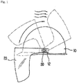
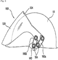
- FIG. 1 illustrates a conventional face protector provided at a safety helmet.
- the conventional face protector 20 is coupled, at opposite ends thereof, to coupling pieces 12 provided at opposite sides of the safety helmet 10 by use of rotating shafts 30, so as to be rotated upward and downward.
- the conventional face protector 20 having the above described configuration, it is rotatable in a circle about the rotating shafts 30.
- the face protector 20 when being rotated upward by a certain angle, the face protector 20 is supported by only the rotating shafts 30. Therefore, there is a problem in that the face protector 20 may be easily lowered by a weight thereof, thus causing inconvenience in use.
- the above described conventional face protector 20 suffers from a large size thereof because it has to be raised to protrude upward from the safety helmet 10 when not in use. Due to the large size, the conventional face protector 20 may receive an excessively large resistance from external environment during movement of the wearer and in particular, cause inconvenience for the wearer in narrow spaces. To solve the inconvenience in use, it is necessary to rotate the face protector beyond an angle of 90 degrees, so as to position the center of gravity of the face protector toward a rear side of the safety helmet. However, when the center of gravity of the face protector is deflected rearward, it may apply a burden to muscles of the wearer's neck.
- US4224694 discloses a face protector for a safety helmet.
- the present invention has been made in view of the above problems, and it is an object of the present invention to provide a face protector for a safety helmet, which can be rotated upward and downward by a predetermined angle while being coupled to the safety helmet, and can be stably secured at an upwardly rotated position thereof with a low wind-resistance and negligible weight-deflection while eliminating the risk of unintentional lowering by a weight thereof.
- a face protector for a safety helmet which is rotated upward and downward by a predetermined angle while being coupled to coupling pieces provided at opposite sides of the safety helmet, so as to protect the wearer's face, comprising: a body configured to protect the wearer's face; a pair of coupling units configured to be fixedly coupled to both the coupling pieces of the safety helmet, respectively; and a plurality of links used to connect the coupling units to opposite rear ends of the body, respectively, so as to restrict rotation of the body, wherein: the body has upper and lower operating shaft holes perforated, respectively, in both the rear ends thereof; each of the coupling units comprises: a fixing piece configured to be fitted to an associated one of the coupling pieces of the safety helmet and adapted to prevent unintentional movement of the coupling unit; and a supporting piece located at the outer side of the fixing piece and having upper and lower supporting shaft holes formed at a protruding portion thereof; and each of the
- elastic rings may be coupled to the shaft pins, which are used to couple the upper and lower links to the upper and lower supporting shaft holes and the upper and lower operating shaft holes, the elastic rings serving to restrict rotation of the shaft pins by an elastic force thereof.
- each coupling unit may be formed at opposite sides thereof with elastic protrusions configured to be coupled to the coupling pieces of the safety helmet in a hook coupling manner.
- the body of the face protector may have a lip formed at an upper end thereof to protrude inward, the lip being adapted to come into close contact with a rim of the safety helmet when the body is rotated downward.
- a face protector for a safety helmet which is coupled to the safety helmet via coupling units and links to come into close contact with a front portion of the helmet when being rotated upward while preventing a lower end thereof from being lifted from a front end portion of the helmet, has the effects of: preventing the wearer's head from colliding with any object above the head in a narrow space; maximizing wearing convenience of the face protector with a low wind-resistance and negligible weight-deflection; and guaranteeing easy and convenient use of the face protector by preventing the face protector from being unintentionally rotated downward by a weight thereof.
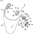
- FIG. 2 is a perspective view illustrating a face protector for use with a safety helmet according to the present invention.
- FIG. 3 is a side sectional view illustrating important parts of the face protector of FIG. 3 .
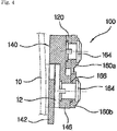
- FIG. 4 is a sectional view taken along the line A-A of FIG. 3 .
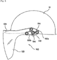
- FIGS. 5 and 6 are side views illustrating the face protector provided at a safety helmet, which is lowered and raised, respectively.
- the face protector 100 for use with a safety helmet 10 comprises a body 120 configured to protect a face of the wearer, a pair of coupling units 140 configured to be fixedly coupled to coupling pieces 12, respectively, which are provided at opposite sides of the safety helmet 10, and a plurality of upper links 160a and lower links 160b used to connect the coupling units 140 to opposite rear ends of the body 120, so as to restrict rotation of the body 120.
- the body 120 is made of a transparent material, to allow the wearer to see in front through the body 120 in a state wherein the body 120 covers the wearer's face.
- the body 120 is formed, at both the rear ends thereof, with a plurality of upper and lower operating shaft holes 122a and 122b so that the upper and lower links 160a and 160b are aligned with the upper and lower operating shaft holes 122a and 122b, respectively, by use of shaft means.
- each upper operating shaft hole 122a is spaced apart from the associated lower operating shaft hole 122b by a predetermined distance in such a manner that they are arranged at opposite upper and lower diagonal positions.
- a lip 124 is formed along an inner periphery of an upper end of the body 120.
- the lip 124 protrudes inward to be caught by a rim of the safety helmet 10 when the body 120 is rotated downward.
- Each of the coupling units 140 is configured such that it is coupled not only to an associated one of the coupling pieces 12 of the safety helmet 10, but also to the associated rear end of the body 120 by use of the upper and lower links 160a and 160b. Accordingly, the coupling units 140 serve to couple the respective rear ends of the body 120 of the face protector 100 to the coupling pieces 12 of the safety helmet 10.
- the two coupling units 140 provided at the face protector 100 has the same configuration and operation as each other and thus, only of them will be described hereinafter.
- the coupling unit 140 includes a fixing piece 142 integrally formed, at opposite sides thereof, with elastic protrusions 144, the fixing piece 142 being configured to be fitted to the associated coupling piece 12 of the safety helmet 10 and adapted to prevent unintentional movement of the coupling unit 140.
- the coupling unit 140 further includes a supporting piece 146 located at the outer side of the fixing piece 142, the supporting piece 126 being formed with upper and lower supporting shaft holes 148a and 148b for allowing the coupling unit 140 to be coupled to the upper and lower links 160a and 160b by use of shaft means. Both the fixing piece 142 and supporting piece 146 are spaced apart from each other by a predetermined distance so that the associated coupling piece 12 of the safety helmet 10 is fitted into a gap between the fixing piece 142 and the supporting piece 146.
- the upper and lower supporting shaft holes 148a and 148b formed in the supporting piece 146 are spaced apart from each other by a predetermined distance in such a manner that they are positioned at opposite upper and lower diagonal positions, to ensure the connection of the upper and lower links 160a and 160b as well as smooth rotation thereof.
- the upper and lower supporting shaft holes 148a and 148b are formed in an outwardly protruding portion of the supporting piece 146, and the outwardly protruding portion has the same thickness as that of the body 120. Accordingly, both the rear ends of the body 120 of the face protector 100 can be guided while coming into close contact with the supporting pieces 146 of both the coupling units 140. Also, with the above described configuration, when the upper and lower supporting shaft holes 148a and 148b and the upper and lower operating shaft holes 122a and 122b are connected to each other, there is no deflection in the height of the upper and lower links 160a and 160b, and the stable connection and operation of the upper and lower links 160a and 160b can be accomplished.
- each fixing piece 142 is provided at opposite sides thereof with the elastic protrusions 144 to be fastened to the associated coupling piece 12 of the safety helmet 10 in a hook coupling manner.
- the elastic protrusions 144 are designed to be easily unfastened from the coupling piece 12 if necessary.
- the links 160a and 160b serve to connect both the rear ends of the body 120 of the face protector 100 to the corresponding coupling units 140, respectively, so as to restrict rotation of the body 120.
- the upper link 160a and the lower link 160b make a pair, and two pairs of the upper and lower links 160a and 160b are provided at both the rear ends of the body 120, respectively.
- each upper link 160a has a pair of connecting shaft holes 162a formed at opposite ends thereof
- each lower link 160b has a pair of connecting shaft holes 162b formed at opposite ends thereof.
- the upper link 160a is connected to the upper operating shaft hole 122a and the upper supporting shaft hole 148a such that a shaft pin 164 penetrates therethrough.
- the lower link 160b is connected to the lower operating shaft hole 122b and the lower supporting shaft hole 148b such that another shaft pine 164 penetrates therethrough.
- the upper and lower links 160a and 160b are rotated simultaneously, such that a recessed edge portion of the upper link 160a comes into close contact with one end of the lower link 160b, so as to prevent further rotation of the body 120.
- the body 120 is located to cover the wearer's face.
- the upper and lower links 160a and 160b are rotated simultaneously, such that the other end of the lower link 160b comes into close contact with an end of the upper link 160a, so as to prevent further rotation of the body 120.
- the body 120 comes into close contact with a front portion of the safety helmet 10 while preventing the lower end of the body 120 from being lifted from the front end portion of the safety helmet 10.
- elastic rings 166 are coupled to the shaft pins 164, which are used to connect the respective connecting shaft holes 162a and 162b formed at both the ends of the upper and lower links 160a and 160b to the upper and lower supporting shaft holes 148a and 148b and the upper and lower operating shaft holes 122a and 122b.
- the elastic rings 166 serve to restrict rotation of the shaft pins 164 by use of an elastic force thereof.
- each shaft pin 164 is penetrated from the upper or lower supporting shaft hole 148a or 148b and the upper or lower operating shaft hole 122a or 122b to the shaft hole 162a or 162b formed at a front or rear end of the upper or lower link 160a or 160b.
- the shaft pin 164 is formed at an end thereof with a hook protrusion or snap protrusion so as not to be easily separated from the above described holes. In the above described coupling manner, it is important to prevent the shaft pins 164 from being easily rotated in their fastened state for preventing the body 120 of the face protector 100 from being unintentionally rotated downward by a weight thereof.
- the elastic rings 166 are coupled to the shaft pins 164 between the upper and lower operating shaft hole 122a and 122b and the shaft holes 162a and 162b of the upper and lower links 160a and 160b and between the upper and lower supporting shaft holes 148a and 148b and the shaft holes 162a and 162b of the upper and lower links 160a and 160b. Thereby, the elastic rings 166 come into close contact with the links 160a and 160b and the body 120, to restrict rotation of the body 120.
- the body 120 of the face protector 100 can be rotated upward and downward in a simplified manner via interaction between the coupling units 140 and the upper and lower links 160a and 160b, and the face protector 100 can guarantee easy and convenient wearing thereof in its upwardly rotated state.
- a face protector for a safety helmet according to the present invention has the following advantageous effects.
- the face protector is coupled to the safety helmet via coupling units and links in such a manner that it comes into close contact with a front portion of the safety helmet when being rotated upward while preventing a lower end thereof from being lifted from a front end portion of the helmet.
- this configuration it is possible to prevent the wearer's head from colliding with any object above the head in a narrow space, to maximize wearing convenience of the face protector with a low wind-resistance and negligible weight-deflection, and to guarantee easy and convenient use of the face protector by preventing the face protector from being unintentionally rotated downward by a weight thereof.
- the face protector according to the present invention can not only be easily attached to the safety helmet, but also be easily rotated upward and downward. In use, the face protector has a minimized distance from the safety helmet, resulting in a compact structure.
- the face protector of the present invention also has a three-dimensional body designed to fit perfectly to the curvature of the human face. This has the effects of increasing a face protecting effect while decreasing the weight of the face protector.
- the present invention is very useful in the field of safety equipment industry.
- the face protector due to the fact that the face protector comes into close contact with a front portion of the safety helmet, the face protector can be affected by only a reduced wind-resistance and negligible weight-deflection. This has the effect of preventing unintentional lowering of the face protector by the weight thereof, and guaranteeing very convenient and easy use of the face protector.
Description
- The present invention relates to a face protector for a safety helmet, and more particularly, to a face protector for a safety helmet, which can be rotated upward and downward by a predetermined angle while being coupled to the safety helmet, and can be stably secured at an upwardly rotated position thereof with a low wind-resistance and negligible weight-deflection while eliminating the risk of unintentional lowering by a weight thereof.
- In general, safety helmets are widely used in a variety of industrial fields to protect workers from unexpected accidents. The safety helmets are provided with a face protector for protecting the wearer's face from light, wind, airborne materials, or physical hazards.
-
FIG. 1 illustrates a conventional face protector provided at a safety helmet. As shown inFIG. 1 , theconventional face protector 20 is coupled, at opposite ends thereof, to couplingpieces 12 provided at opposite sides of thesafety helmet 10 by use of rotatingshafts 30, so as to be rotated upward and downward. In theconventional face protector 20 having the above described configuration, it is rotatable in a circle about the rotatingshafts 30. - However, with the above described rotating structure, when being rotated upward by a certain angle, the
face protector 20 is supported by only the rotatingshafts 30. Therefore, there is a problem in that theface protector 20 may be easily lowered by a weight thereof, thus causing inconvenience in use. - Furthermore, the above described
conventional face protector 20 suffers from a large size thereof because it has to be raised to protrude upward from thesafety helmet 10 when not in use. Due to the large size, theconventional face protector 20 may receive an excessively large resistance from external environment during movement of the wearer and in particular, cause inconvenience for the wearer in narrow spaces. To solve the inconvenience in use, it is necessary to rotate the face protector beyond an angle of 90 degrees, so as to position the center of gravity of the face protector toward a rear side of the safety helmet. However, when the center of gravity of the face protector is deflected rearward, it may apply a burden to muscles of the wearer's neck. Also, in a state of being raised when not in use, there is a problem in that a lower end of the raised face protector is lifted from a front end of the safety helmet to thereby be located at a disadvantageous position receiving a considerably large resistance against wind. This may result in unintentional excessive rearward rotation of the face protector by wind. -
US4224694 discloses a face protector for a safety helmet. - Therefore, the present invention has been made in view of the above problems, and it is an object of the present invention to provide a face protector for a safety helmet, which can be rotated upward and downward by a predetermined angle while being coupled to the safety helmet, and can be stably secured at an upwardly rotated position thereof with a low wind-resistance and negligible weight-deflection while eliminating the risk of unintentional lowering by a weight thereof.
- In accordance with an aspect of the present invention, the above and other objects can be accomplished by the provision of a face protector for a safety helmet, which is rotated upward and downward by a predetermined angle while being coupled to coupling pieces provided at opposite sides of the safety helmet, so as to protect the wearer's face, comprising: a body configured to protect the wearer's face; a pair of coupling units configured to be fixedly coupled to both the coupling pieces of the safety helmet, respectively; and a plurality of links used to connect the coupling units to opposite rear ends of the body, respectively, so as to restrict rotation of the body, wherein: the body has upper and lower operating shaft holes perforated, respectively, in both the rear ends thereof; each of the coupling units comprises: a fixing piece configured to be fitted to an associated one of the coupling pieces of the safety helmet and adapted to prevent unintentional movement of the coupling unit; and a supporting piece located at the outer side of the fixing piece and having upper and lower supporting shaft holes formed at a protruding portion thereof; and each of the links comprises upper and lower connecting shaft holes formed in opposite ends thereof, the links including upper links to connect the upper operating shaft hole with the upper supporting shaft hole through a shaft pin, and lower links to connect the lower operating shaft hole with the lower supporting shaft hole through a shaft pin, whereby, if the body is rotated downward, a recessed edge portion of the upper link comes into close contact with one end of the lower link to restrict rotation of the body after being located in front of the wearer's face, and if the body is rotated upward, the other end of the lower link comes into close contact with an end of the upper link to restrict rotation of the body while preventing a lower end of the body from being lifted from a front end portion of the safety helmet and allowing the body to come into close contact with a front portion of the safety helmet.
- Preferably, elastic rings may be coupled to the shaft pins, which are used to couple the upper and lower links to the upper and lower supporting shaft holes and the upper and lower operating shaft holes, the elastic rings serving to restrict rotation of the shaft pins by an elastic force thereof.
- Preferably, the fixing piece of each coupling unit may be formed at opposite sides thereof with elastic protrusions configured to be coupled to the coupling pieces of the safety helmet in a hook coupling manner.
- Preferably, the body of the face protector may have a lip formed at an upper end thereof to protrude inward, the lip being adapted to come into close contact with a rim of the safety helmet when the body is rotated downward.
- According to the present invention, a face protector for a safety helmet, which is coupled to the safety helmet via coupling units and links to come into close contact with a front portion of the helmet when being rotated upward while preventing a lower end thereof from being lifted from a front end portion of the helmet, has the effects of: preventing the wearer's head from colliding with any object above the head in a narrow space; maximizing wearing convenience of the face protector with a low wind-resistance and negligible weight-deflection; and guaranteeing easy and convenient use of the face protector by preventing the face protector from being unintentionally rotated downward by a weight thereof.
- The above and other objects, features and other advantages of the present invention will be more clearly understood from the following detailed description taken in conjunction with the accompanying drawings, in which:
-
FIG. 1 is a side view illustrating a safety helmet having a face protector according to the prior art; -
FIG. 2 is a perspective view illustrating a face protector for use with a safety helmet according to the present invention; -
FIG. 3 is a side sectional view illustrating important parts of the face protector ofFIG. 2 ; -
FIG. 4 is a sectional view taken along the line A-A ofFIG. 3 ; -
FIG. 5 is a side view illustrating the face protector provided at a safety helmet, which is lowered; and -
FIG. 6 is a side view illustrating the face protector provided at a safety helmet, which is raised. - Now, preferred embodiments of the present invention will be explained in detail with reference to the accompanying drawings.
-
FIG. 2 is a perspective view illustrating a face protector for use with a safety helmet according to the present invention.FIG. 3 is a side sectional view illustrating important parts of the face protector ofFIG. 3 .FIG. 4 is a sectional view taken along the line A-A ofFIG. 3 .FIGS. 5 and6 are side views illustrating the face protector provided at a safety helmet, which is lowered and raised, respectively. - As shown in
FIGS. 2 to 6 , theface protector 100 for use with asafety helmet 10 according to the present invention comprises abody 120 configured to protect a face of the wearer, a pair ofcoupling units 140 configured to be fixedly coupled tocoupling pieces 12, respectively, which are provided at opposite sides of thesafety helmet 10, and a plurality ofupper links 160a andlower links 160b used to connect thecoupling units 140 to opposite rear ends of thebody 120, so as to restrict rotation of thebody 120. - The
body 120 is made of a transparent material, to allow the wearer to see in front through thebody 120 in a state wherein thebody 120 covers the wearer's face. Thebody 120 is formed, at both the rear ends thereof, with a plurality of upper and loweroperating shaft holes 122a and 122b so that the upper andlower links operating shaft holes 122a and 122b, respectively, by use of shaft means. - To be aligned with the upper and
lower links operating shaft hole 122b by a predetermined distance in such a manner that they are arranged at opposite upper and lower diagonal positions. - Preferably, a
lip 124 is formed along an inner periphery of an upper end of thebody 120. Thelip 124 protrudes inward to be caught by a rim of thesafety helmet 10 when thebody 120 is rotated downward. - Each of the
coupling units 140 is configured such that it is coupled not only to an associated one of thecoupling pieces 12 of thesafety helmet 10, but also to the associated rear end of thebody 120 by use of the upper andlower links coupling units 140 serve to couple the respective rear ends of thebody 120 of theface protector 100 to thecoupling pieces 12 of thesafety helmet 10. The twocoupling units 140 provided at theface protector 100 has the same configuration and operation as each other and thus, only of them will be described hereinafter. - Considering the configuration of the
coupling unit 140 in detail, thecoupling unit 140 includes afixing piece 142 integrally formed, at opposite sides thereof, withelastic protrusions 144, thefixing piece 142 being configured to be fitted to the associatedcoupling piece 12 of thesafety helmet 10 and adapted to prevent unintentional movement of thecoupling unit 140. Thecoupling unit 140 further includes a supportingpiece 146 located at the outer side of thefixing piece 142, the supporting piece 126 being formed with upper and lower supportingshaft holes 148a and 148b for allowing thecoupling unit 140 to be coupled to the upper andlower links fixing piece 142 and supportingpiece 146 are spaced apart from each other by a predetermined distance so that the associatedcoupling piece 12 of thesafety helmet 10 is fitted into a gap between thefixing piece 142 and the supportingpiece 146. - Similar to the above described upper and lower
operating shaft holes 122a and 122b, the upper and lower supportingshaft holes 148a and 148b formed in the supportingpiece 146 are spaced apart from each other by a predetermined distance in such a manner that they are positioned at opposite upper and lower diagonal positions, to ensure the connection of the upper andlower links - The upper and lower supporting
shaft holes 148a and 148b are formed in an outwardly protruding portion of the supportingpiece 146, and the outwardly protruding portion has the same thickness as that of thebody 120. Accordingly, both the rear ends of thebody 120 of theface protector 100 can be guided while coming into close contact with the supportingpieces 146 of both thecoupling units 140. Also, with the above described configuration, when the upper and lower supportingshaft holes 148a and 148b and the upper and loweroperating shaft holes 122a and 122b are connected to each other, there is no deflection in the height of the upper andlower links lower links - As stated above, each
fixing piece 142 is provided at opposite sides thereof with theelastic protrusions 144 to be fastened to the associatedcoupling piece 12 of thesafety helmet 10 in a hook coupling manner. Preferably, theelastic protrusions 144 are designed to be easily unfastened from thecoupling piece 12 if necessary. - The
links body 120 of theface protector 100 to thecorresponding coupling units 140, respectively, so as to restrict rotation of thebody 120. Theupper link 160a and thelower link 160b make a pair, and two pairs of the upper andlower links body 120, respectively. - Specifically, each
upper link 160a has a pair of connectingshaft holes 162a formed at opposite ends thereof, and eachlower link 160b has a pair of connecting shaft holes 162b formed at opposite ends thereof. Theupper link 160a is connected to the upper operating shaft hole 122a and the upper supporting shaft hole 148a such that ashaft pin 164 penetrates therethrough. Similarly, thelower link 160b is connected to the loweroperating shaft hole 122b and the lower supportingshaft hole 148b such that anothershaft pine 164 penetrates therethrough. In a state wherein the upper andlower links body 120 through thecoupling unit 140, if thebody 120 is rotated downward, theupper link 160a pushes thelower link 160b to come into close contact with thelower link 160b, thereby acting to prevent thebody 120 from being rotated unintentionally after being located in front of the wearer's face. Conversely, if thebody 120 is rotated upward, thelower link 160b pushes theupper link 160a to come into close contact with theupper link 160a, thereby acting to cause the lower end of thebody 120 to come into close contact with a front end portion of thesafety helmet 10 without being lifted from the front end portion. - More specifically, when the
body 120 is rotated downward, as shown inFIG. 5 , the upper andlower links upper link 160a comes into close contact with one end of thelower link 160b, so as to prevent further rotation of thebody 120. In a state wherein the end of thelower link 160b is closely engaged with the recessed edge portion of theupper link 160a, thebody 120 is located to cover the wearer's face. - Also, when the
body 120 is rotated upward, as shown inFIG. 6 , the upper andlower links lower link 160b comes into close contact with an end of theupper link 160a, so as to prevent further rotation of thebody 120. In a state wherein the other end of thelower link 160b comes into close contact with the facing end of theupper link 160a, thebody 120 comes into close contact with a front portion of thesafety helmet 10 while preventing the lower end of thebody 120 from being lifted from the front end portion of thesafety helmet 10. - As will be understood from the above description, the respective ends of the upper and
lower links - With interaction between the upper and
lower links body 120 is rotated upward, thebody 120 is horizontally moved rearward after being rotated by a predetermined angle, rather than being further rotated in a circle. This has the effect of preventing the lower end of thebody 120 from being lifted from the front end portion of thebody 120, thus allowing thebody 120 to come into close contact with the front portion of thesafety helmet 10. - In the present invention, additionally,
elastic rings 166 are coupled to the shaft pins 164, which are used to connect the respective connectingshaft holes 162a and 162b formed at both the ends of the upper andlower links shaft holes 148a and 148b and the upper and loweroperating shaft holes 122a and 122b. Theelastic rings 166 serve to restrict rotation of the shaft pins 164 by use of an elastic force thereof. - Specifically, each
shaft pin 164 is penetrated from the upper or lower supportingshaft hole 148a or 148b and the upper or loweroperating shaft hole 122a or 122b to theshaft hole 162a or 162b formed at a front or rear end of the upper orlower link shaft pin 164 is formed at an end thereof with a hook protrusion or snap protrusion so as not to be easily separated from the above described holes. In the above described coupling manner, it is important to prevent the shaft pins 164 from being easily rotated in their fastened state for preventing thebody 120 of theface protector 100 from being unintentionally rotated downward by a weight thereof. For this, theelastic rings 166 are coupled to the shaft pins 164 between the upper and loweroperating shaft hole 122a and 122b and theshaft holes 162a and 162b of the upper andlower links shaft holes 148a and 148b and theshaft holes 162a and 162b of the upper andlower links elastic rings 166 come into close contact with thelinks body 120, to restrict rotation of thebody 120. - With the above described configuration of the
face protector 100, thebody 120 of theface protector 100 can be rotated upward and downward in a simplified manner via interaction between thecoupling units 140 and the upper andlower links face protector 100 can guarantee easy and convenient wearing thereof in its upwardly rotated state. - As apparent from the above description, a face protector for a safety helmet according to the present invention has the following advantageous effects.
- Firstly, the face protector is coupled to the safety helmet via coupling units and links in such a manner that it comes into close contact with a front portion of the safety helmet when being rotated upward while preventing a lower end thereof from being lifted from a front end portion of the helmet. With this configuration, it is possible to prevent the wearer's head from colliding with any object above the head in a narrow space, to maximize wearing convenience of the face protector with a low wind-resistance and negligible weight-deflection, and to guarantee easy and convenient use of the face protector by preventing the face protector from being unintentionally rotated downward by a weight thereof.
- Further, the face protector according to the present invention can not only be easily attached to the safety helmet, but also be easily rotated upward and downward. In use, the face protector has a minimized distance from the safety helmet, resulting in a compact structure. The face protector of the present invention also has a three-dimensional body designed to fit perfectly to the curvature of the human face. This has the effects of increasing a face protecting effect while decreasing the weight of the face protector.
- Furthermore, when not in use, there is no considerable variation in the size of the helmet even in a state wherein the face protector is raised. This reduces inconvenience in motion of the wearer in a narrow space and prevents the wearer's head from colliding with any objects above the wearer's head in the narrow space, thereby achieving an ergonomic structure of the face protector. Accordingly, it can be said that the present invention is very useful in the field of safety equipment industry.
- Finally, due to the fact that the face protector comes into close contact with a front portion of the safety helmet, the face protector can be affected by only a reduced wind-resistance and negligible weight-deflection. This has the effect of preventing unintentional lowering of the face protector by the weight thereof, and guaranteeing very convenient and easy use of the face protector.
- Although the preferred embodiments of the present invention have been disclosed for illustrative purposes, those skilled in the art will appreciate that various modifications, additions and substitutions are possible, without departing from the scope of the invention as disclosed in the accompanying claims.
Claims (4)
- A face protector (100) for a safety helmet (10), which is rotated upward and downward by a predetermined angle while being coupled to coupling pieces (12) provided at opposite sides of the safety helmet, so as to protect the wearer's face, comprising:a body (120) configured to protect the wearer's face;a pair of coupling units (140) configured to be fixedly coupled to both the coupling pieces of the safety helmet, respectively; anda plurality of links (160a, 160b) used to connect the coupling units to opposite rear ends of the body, respectively, so as to restrict rotation of the body,wherein:the body has upper and lower operating shaft holes (122a, 122b) perforated, respectively, in both the rear ends thereof;each of the coupling units comprises:characterised in thata fixing piece (142) configured to be fitted to an associated one of the coupling pieces of the safety helmet and adapted to prevent unintentional movement of the coupling unit; anda supporting piece (146) located at the outer side of the fixing piece and having upper and lower supporting shaft holes (148a, 148b) formed at a protruding portion thereof; andeach of the links comprises upper and lower connecting shaft holes (162a, 162b) formed in opposite ends thereof, the links including upper links to connect the upper operating shaft hole with the upper supporting shaft hole through a shaft pin (164), and lower links to connect the lower operating shaft hole with the lower supporting shaft hole through a shaft pin,
if the body is rotated downward, a recessed edge portion of the upper link comes into close contact with one end of the lower link to restrict rotation of the body after being located in front of the wearer's face, and
if the body is rotated upward, the other end of the lower link comes into close contact with an end of the upper link to restrict rotation of the body while preventing a lower end of the body from being lifted from a front end portion of the safety helmet and allowing the body to come into close contact with a front portion of the safety helmet. - The face protector (100) according to claim 1, wherein elastic rings (166) are coupled to the shaft pins (164), which are used to couple the upper and lower links (160a, 160b) to the upper and lower supporting shaft holes (148a, 148b) and the upper and lower operating shaft holes, the elastic rings serving to restrict rotation of the shaft pins by an elastic force thereof.
- The face protector (100) according to claim 1 or 2, wherein the fixing piece (142) of each coupling unit (140) is formed at opposite sides thereof with elastic protrusions (144) configured to be coupled to the coupling pieces (12) of the safety helmet (10) in a hook coupling manner.
- The face protector (100) according to claim 3, wherein the body (120) of the face protector has a lip (124) formed at an upper end thereof to protrude inward, the lip being adapted to come into close contact with a rim of the safety helmet (10) when the body is rotated downward.
Applications Claiming Priority (2)
| Application Number | Priority Date | Filing Date | Title |
|---|---|---|---|
| KR1020060033059A KR100748611B1 (en) | 2006-04-12 | 2006-04-12 | Face shield for safety helmet |
| PCT/KR2006/004070 WO2007117066A1 (en) | 2006-04-12 | 2006-10-10 | Face shield for safety helmet |
Publications (3)
| Publication Number | Publication Date |
|---|---|
| EP2004000A1 EP2004000A1 (en) | 2008-12-24 |
| EP2004000A4 EP2004000A4 (en) | 2015-09-09 |
| EP2004000B1 true EP2004000B1 (en) | 2017-02-15 |
Family
ID=38581318
Family Applications (1)
| Application Number | Title | Priority Date | Filing Date |
|---|---|---|---|
| EP06799150.5A Active EP2004000B1 (en) | 2006-04-12 | 2006-10-10 | Face shield for safety helmet |
Country Status (4)
| Country | Link |
|---|---|
| US (1) | US20090313745A1 (en) |
| EP (1) | EP2004000B1 (en) |
| KR (1) | KR100748611B1 (en) |
| WO (1) | WO2007117066A1 (en) |
Cited By (2)
| Publication number | Priority date | Publication date | Assignee | Title |
|---|---|---|---|---|
| US10912344B2 (en) | 2018-12-03 | 2021-02-09 | Msa Technology, Llc | Helmet with accessory attachment rail |
| US11213089B2 (en) | 2019-06-04 | 2022-01-04 | Msa Technology, Llc | Protective helmet with face protection shield and linkage mechanism |
Families Citing this family (14)
| Publication number | Priority date | Publication date | Assignee | Title |
|---|---|---|---|---|
| FR2910789A1 (en) * | 2006-12-27 | 2008-07-04 | Msa Gallet Soc Par Actions Sim | Protective helmet i.e. fireman's helmet, has main outer shell with longitudinal symmetric plane and removably fixed on sub shell by using connecting unit, headband liner fixed with sub shell, and chin strap maintaining helmet on user's head |
| CH700540A2 (en) * | 2009-03-02 | 2010-09-15 | Sperian Welding Prot Ag | Adapter system and adapter for mask. |
| US8555424B2 (en) | 2009-03-16 | 2013-10-15 | Danny Higgins | Helmet having a guiding mechanism for a compatible visor |
| CA2658238C (en) * | 2009-03-16 | 2010-05-18 | Danny Higgins | Helmet having a guiding mechanism for a compatible visor and a visor for such a helmet |
| US8434167B2 (en) * | 2011-08-03 | 2013-05-07 | Honeywell International Inc. | Universal dual-pivot face shield assembly for a hard hat |
| KR101372886B1 (en) * | 2012-05-31 | 2014-03-10 | 오토스테크 주식회사 | Detachabel safety goggle for safety helmet |
| US11134741B2 (en) * | 2017-05-25 | 2021-10-05 | E.D. Bullard Company | Protective helmet with a retractable and removable visor |
| USD955649S1 (en) * | 2019-10-31 | 2022-06-21 | Uvex Arbeitsschutz Gmbh | Head guard |
| KR102140899B1 (en) | 2019-11-14 | 2020-08-04 | 송재윤 | safety helmet having face cover |
| USD964657S1 (en) * | 2020-12-31 | 2022-09-20 | Erb Industries, Inc. | Helmet with face shield |
| EP4287902A1 (en) * | 2021-02-08 | 2023-12-13 | Milwaukee Electric Tool Corporation | Hard hat face shield attachment system |
| TWI740798B (en) * | 2021-04-13 | 2021-09-21 | 廣權精密有限公司 | Lens pivot structure of cap body |
| US11805839B2 (en) * | 2022-01-27 | 2023-11-07 | Chien-Hung Lu | Headwear with a protective shield |
| US20230301388A1 (en) * | 2022-03-24 | 2023-09-28 | Paulson Manufacturing Corporation | Weight compensating bracket |
Family Cites Families (15)
| Publication number | Priority date | Publication date | Assignee | Title |
|---|---|---|---|---|
| US2649019A (en) * | 1949-09-02 | 1953-08-18 | Us Air Force | Contractible head mount for binoculars |
| US2860343A (en) * | 1955-10-27 | 1958-11-18 | Leonard P Frieder | Headgear with retractable eye shield |
| SE408851B (en) * | 1977-07-01 | 1979-07-16 | T G Palmaer | DEVICE IN THE SAFETY HELMET OR A SIMILAR CARRYING BODY |
| US4442551A (en) * | 1982-12-22 | 1984-04-17 | Hellberg Protection Ab | Adapter for a protective helmet |
| DE8333228U1 (en) * | 1983-11-19 | 1984-03-01 | Fondermann & Co GmbH, 5657 Haan | Hard hat |
| US4766609A (en) * | 1987-03-31 | 1988-08-30 | Firequip Helmets, Inc. | Fire fighter helmet and face shield |
| KR930000905Y1 (en) * | 1991-06-22 | 1993-02-27 | 조진휘 | Helmet |
| JPH05214604A (en) * | 1992-01-31 | 1993-08-24 | Shoei Kako Kk | Shield plate controller in helmet |
| JPH05272004A (en) * | 1992-03-23 | 1993-10-19 | Shoei Kako Kk | Structure for fitting shield plate to helmets |
| FR2716089B1 (en) * | 1994-02-16 | 1996-05-10 | Ouest Negoce Achats Materiaux | Protective helmet with a visor, particularly useful as a construction helmet. |
| US5675875A (en) * | 1996-08-01 | 1997-10-14 | Servatius; Richard James | Adjustable breakaway |
| JPH10212618A (en) * | 1997-01-22 | 1998-08-11 | Tomosaburo Hosomi | Opening and closing structure of face shield for helmet and the like |
| US5978973A (en) * | 1997-12-12 | 1999-11-09 | Bauer, Inc. | Fastener for use on a protective helmet |
| JP2003082518A (en) * | 2001-09-07 | 2003-03-19 | Tanizawa Seisakusho Ltd | Helmet with face shield |
| FR2886521B1 (en) * | 2005-06-03 | 2007-09-07 | Cbm Distrib Entpr Unipersonnel | HELMET FOR MOBILE VISOR PROTECTION |
-
2006
- 2006-04-12 KR KR1020060033059A patent/KR100748611B1/en active IP Right Grant
- 2006-10-10 US US11/791,054 patent/US20090313745A1/en not_active Abandoned
- 2006-10-10 EP EP06799150.5A patent/EP2004000B1/en active Active
- 2006-10-10 WO PCT/KR2006/004070 patent/WO2007117066A1/en active Application Filing
Non-Patent Citations (1)
| Title |
|---|
| None * |
Cited By (2)
| Publication number | Priority date | Publication date | Assignee | Title |
|---|---|---|---|---|
| US10912344B2 (en) | 2018-12-03 | 2021-02-09 | Msa Technology, Llc | Helmet with accessory attachment rail |
| US11213089B2 (en) | 2019-06-04 | 2022-01-04 | Msa Technology, Llc | Protective helmet with face protection shield and linkage mechanism |
Also Published As
| Publication number | Publication date |
|---|---|
| EP2004000A4 (en) | 2015-09-09 |
| KR100748611B1 (en) | 2007-08-13 |
| EP2004000A1 (en) | 2008-12-24 |
| WO2007117066A1 (en) | 2007-10-18 |
| US20090313745A1 (en) | 2009-12-24 |
Similar Documents
| Publication | Publication Date | Title |
|---|---|---|
| EP2004000B1 (en) | Face shield for safety helmet | |
| US5357292A (en) | Eyeglasses with adjustable temple inclination | |
| US5483699A (en) | Face shield with chin contacting element | |
| EP3154386B1 (en) | Removable shield for protective headwear | |
| US9408430B2 (en) | Protective helmet and screen | |
| JP4775659B2 (en) | goggles | |
| JP5531043B2 (en) | Shield member and protective cap | |
| CN109561750A (en) | Protective helmet | |
| JPS6024201B2 (en) | safety helmet | |
| KR102587766B1 (en) | Chin guard positioning assembly and helmet using the same | |
| CA1295089C (en) | Face protective device | |
| EP3749265B1 (en) | Combination of a goggle and a face mask | |
| US2890457A (en) | Face mask | |
| US6397396B1 (en) | Ball cap with attached sunglasses | |
| JP2501415B2 (en) | Helmet | |
| KR102641350B1 (en) | Chin guard positioning assembly and helmet using the same | |
| WO2013100238A1 (en) | Cap having a double brim | |
| US20070067887A1 (en) | Safety hat with adjustable visor | |
| EP3692847B1 (en) | Visor locking mechanism and helmet | |
| KR100993836B1 (en) | Protective helmet | |
| JP3231032U (en) | Face shield | |
| EP1101419B1 (en) | Crash-helmet for motorcyclists | |
| US20100024096A1 (en) | Skylight forehead rim safety hard hat | |
| US20170224040A1 (en) | Cap having folding visor | |
| CA2145720A1 (en) | Sports mask |
Legal Events
| Date | Code | Title | Description |
|---|---|---|---|
| PUAI | Public reference made under article 153(3) epc to a published international application that has entered the european phase |
Free format text: ORIGINAL CODE: 0009012 |
|
| 17P | Request for examination filed |
Effective date: 20070503 |
|
| RBV | Designated contracting states (corrected) |
Designated state(s): DE FR |
|
| RBV | Designated contracting states (corrected) |
Designated state(s): DE FR |
|
| DAX | Request for extension of the european patent (deleted) | ||
| REG | Reference to a national code |
Ref country code: DE Ref legal event code: R079 Ref document number: 602006051737 Country of ref document: DE Free format text: PREVIOUS MAIN CLASS: A42B0003180000 Ipc: A42B0003220000 |
|
| RA4 | Supplementary search report drawn up and despatched (corrected) |
Effective date: 20150811 |
|
| RIC1 | Information provided on ipc code assigned before grant |
Ipc: A42B 3/22 20060101AFI20150805BHEP |
|
| GRAP | Despatch of communication of intention to grant a patent |
Free format text: ORIGINAL CODE: EPIDOSNIGR1 |
|
| INTG | Intention to grant announced |
Effective date: 20160907 |
|
| GRAS | Grant fee paid |
Free format text: ORIGINAL CODE: EPIDOSNIGR3 |
|
| GRAA | (expected) grant |
Free format text: ORIGINAL CODE: 0009210 |
|
| AK | Designated contracting states |
Kind code of ref document: B1 Designated state(s): DE FR |
|
| REG | Reference to a national code |
Ref country code: DE Ref legal event code: R096 Ref document number: 602006051737 Country of ref document: DE |
|
| REG | Reference to a national code |
Ref country code: FR Ref legal event code: PLFP Year of fee payment: 12 |
|
| REG | Reference to a national code |
Ref country code: DE Ref legal event code: R097 Ref document number: 602006051737 Country of ref document: DE |
|
| PLBE | No opposition filed within time limit |
Free format text: ORIGINAL CODE: 0009261 |
|
| STAA | Information on the status of an ep patent application or granted ep patent |
Free format text: STATUS: NO OPPOSITION FILED WITHIN TIME LIMIT |
|
| 26N | No opposition filed |
Effective date: 20171116 |
|
| REG | Reference to a national code |
Ref country code: FR Ref legal event code: PLFP Year of fee payment: 13 |
|
| PGFP | Annual fee paid to national office [announced via postgrant information from national office to epo] |
Ref country code: FR Payment date: 20230808 Year of fee payment: 18 |
|
| PGFP | Annual fee paid to national office [announced via postgrant information from national office to epo] |
Ref country code: DE Payment date: 20230816 Year of fee payment: 18 |