EP2003756A1 - Gas-insulated electric power apparatus - Google Patents
Gas-insulated electric power apparatus Download PDFInfo
- Publication number
- EP2003756A1 EP2003756A1 EP06730831A EP06730831A EP2003756A1 EP 2003756 A1 EP2003756 A1 EP 2003756A1 EP 06730831 A EP06730831 A EP 06730831A EP 06730831 A EP06730831 A EP 06730831A EP 2003756 A1 EP2003756 A1 EP 2003756A1
- Authority
- EP
- European Patent Office
- Prior art keywords
- vessel
- flange
- gas
- insulated
- shape
- Prior art date
- Legal status (The legal status is an assumption and is not a legal conclusion. Google has not performed a legal analysis and makes no representation as to the accuracy of the status listed.)
- Granted
Links
Images



Classifications
-
- H—ELECTRICITY
- H02—GENERATION; CONVERSION OR DISTRIBUTION OF ELECTRIC POWER
- H02B—BOARDS, SUBSTATIONS OR SWITCHING ARRANGEMENTS FOR THE SUPPLY OR DISTRIBUTION OF ELECTRIC POWER
- H02B13/00—Arrangement of switchgear in which switches are enclosed in, or structurally associated with, a casing, e.g. cubicle
- H02B13/02—Arrangement of switchgear in which switches are enclosed in, or structurally associated with, a casing, e.g. cubicle with metal casing
- H02B13/035—Gas-insulated switchgear
- H02B13/045—Details of casing, e.g. gas tightness
-
- H—ELECTRICITY
- H02—GENERATION; CONVERSION OR DISTRIBUTION OF ELECTRIC POWER
- H02G—INSTALLATION OF ELECTRIC CABLES OR LINES, OR OF COMBINED OPTICAL AND ELECTRIC CABLES OR LINES
- H02G5/00—Installations of bus-bars
- H02G5/06—Totally-enclosed installations, e.g. in metal casings
- H02G5/066—Devices for maintaining distance between conductor and enclosure
- H02G5/068—Devices for maintaining distance between conductor and enclosure being part of the junction between two enclosures
Definitions
- the present invention relates to a gas-insulated power apparatus in which contiguous vessels are coupled by way of flanges of respectives thereof and a power conductor insulated from the vessel by an insulating gas is included in the vessel.
- gas-insulated apparatus of a gas-insulated opening/closing apparatus a gas-insulated transformation apparatus, a gas-insulated bus or the like, a plurality of vessels are connected in airtight, and a power apparatus main body of a circuit breaker, a disconnecting switch, a grounding switch, a power conductor or the like is included in the hermetically closed vessel connected in airtight and enclosed with an insulating gas.
- a vessel of a gas-insulated bus led from the gas-insulated opening/closing apparatus or the like is coupled to a vessel of the gas-insulted opening/closing apparatus by fastening flange portions of respectives thereof by a bolt.
- a bellows in series coupling is used for the vessel per se of the gas-insulated bus in order to absorb thermal elongation/contraction of the gas-insulated bus per se (for example, refer to Patent Reference 1).
- Patent Reference 1 JP-A-2003-51440 ( Fig. 1 and explanation thereof)
- the vessel of the gas-insulated bus led out from the gas-insulated opening/closing apparatus or the like is coupled with the vessel of the gas-insulated opening/closing apparatus by fastening the respective flanges by the bolt
- a direction of leading out the gas-insulated bus also referred to as angle swinging
- the vessel, the flange or the like is designed for each product specification.
- the invention has been carried out in view of the above-described actual situation, it is a principal object thereof to realize a mechanism having a degree of freedom capable of dealing therewith without depending only on a design for each product specification and it is other object thereof to realize a mechanism capable of being used as a substitute for the bellows.
- a gas-insulated power apparatus of the invention is a gas-insulated power apparatus in which contiguous vessels are coupled by way of flanges of respectives thereof and power conductors insulated from the vessels by an insulating gas are included in the vessels, wherein the contiguous vessels are coupled by squeezing a flange of the vessel on one side to be coupled by a pressing member screwed to a flange of the vessel on other side and a flange of the vessel on other side, and positions of the vessel on one side and the vessel on other side to be coupled relative to each other in a peripheral direction of the flange can be shifted.
- a gas-insulated power apparatus is a gas-insulated power apparatus comprising a first and a second vessel including power conductors insulated by a gas and a connection vessel for connecting the first and the second vessel, wherein at least one of coupling of the first vessel and the connection vessel contiguous to each other and coupling of the second vessel and the connection vessel contiguous to each other is carried out by squeezing a flange of the vessel on one side to be coupled by a pressing member screwed to a flange of the vessel on other side and a flange of the vessel on other side, and positions of the first vessel and the second vessel relative to each other can be permitted to change.
- the contiguous vessels are coupled by way of the flanges of the respectives, and the power conductors insulated from the vessels by the insulating gas are included in the vessels, the contiguous vessels are coupled by squeezing the flange of the vessel on one side to be coupled by the pressing member screwed to the flange of the vessel on other side and the flange of the vessel on other side, and therefore, the positions of the vessel on one side and the vessel on other side to be coupled relative to each other in the peripheral direction of the flange can be shifted, and therefore, integration or installation of various products can flexibly be dealt with without depending only on design for respective product specifications.
- the gas-insulated power apparatus comprising the first and the second vessels including the power conductors insulated by the gas and the connection vessel for connecting the first vessel and the second vessel, wherein at least one of coupling of the first vessel and the connection vessel contiguous to each other and coupling of the second vessel and the connection vessel contiguous to each other is carried out by squeezing the flange of the vessel on one side to be coupled by the pressing member screwed to the flange of the vessel on other side and the flange of the vessel on other side, and therefore, the positions of the first vessel and the second vessel relative to each other can be permitted to change, and therefore, integration or installation of various products can flexibly be dealt with without depending only on design for respective product specifications, further, the invention can be used as a substitute for a bellows.
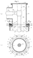
- FIG. 1 illustrates views showing an example of an essential portion of a gas-insulated power apparatus
- Fig. 1(a) is a vertical sectional side view
- Fig. 1(b) is a cross-sectional plane view viewing a section at a line Ib-Ib of Fig. 1(a) in an arrow mark direction.
- Fig. 1 (a) and Fig. 1(b) the same portion are attached with the same notations.
- FIG. 1(a) and Fig. 1(b) there is exemplified an example of a gas-insulated power apparatus 1 in which contiguous vessels 11, 12 are coupled by way of flanges 111, 121 of respectives thereof, and power conductors 112, 122 insulated from the vessels 11, 12 by an insulating gas 13 are included in the corresponding vessels 11, 12, and the contiguous vessels 11, 12 are coupled by squeezing the flange 111 of the vessel 11 on one side to be coupled by a pressing member 14 screwed to the flange 121 of the vessel 12 on other side and the flange 121 of the vessel 12 on other side.
- the vessels 11, 12 are constituted by a ring-like shape, and the respective flanges 111, 121 are constituted by a ring-like shape.
- a plurality of pieces 141, 142 are arranged in a ring-like shape along the flanges 111, 121 in the ring-like shape.
- the power conductors 112, 122 at inside of the respective vessels 11, 12 are coaxially arranged, the coaxial power conductors 112, 122 are connected by an in-vessel power conductor connector 151 of a tulip contact or the like permitting the power conductors 112, 122 to elongate and contract in an axial direction and permitting the power conductors 112, 122 to pivot in a peripheral direction.
- the power conductors 112, 122 at inside of the vessels 11, 12 are insulated from the vessels 11, 12 by a column-like insulating spacer 1131 attached to an end portion hermetically closing lid 113 of the at least one vessel 11.
- a branch pipe shape vessel 16 is connected to the at least one vessel 11, the power conductor 112 at inside of the vessel 11 is connected with a power conductor 161 at inside of the branch pipe shape vessel 16 by way of a power conductor connector 152 at inside of the branch pipe shape vessel permitting the power conductor 161 at inside of the branch pipe shape vessel 16 to elongate and contract in an axial direction, and the power conductor 161 at inside of the branch pipe shape vessel 16 is insulated from the branch pipe shape vessel 16 and the vessel 11 by the column-like insulating spacer 1131 for insulating the power conductor 112 at inside of the vessel 11 from the vessel 11.
- the gas-insulated apparatus when viewed by changing a view point, includes the first and the second vessels 12, 16 including the power conductors 122, 161 insulated by the gas and the connecting vessel 11 for connecting the first vessel 12 and the second vessel 16, and at least one of coupling of the first vessel 12 and the connecting vessel 11 contiguous to each other and coupling of the second vessel 16 and the connecting vessel 11 contiguous to each other is carried out by squeezing the flange 111 of the vessel 11 on one side to be coupled by the pressing member 14 screwed to the flange 121 of the vessel 12 on other side and the flange 121 of the vessel 12 on other side.
- All of the included power conductors 112, 122, 161 of respectives of the first vessel 12, the second vessel 16, and the connecting vessel 11 are insulated from the corresponding vessels 11, 12, 16 by the column-like insulating spacer 1131 attached to the end portion hermetically closing lid 113 of the vessel 11.
- the two flanges 111, 121 are permitted to slide relative to each other in a peripheral direction and airtightness between the two flanges 111, 121 is maintained.
- the flange 121 and the pressing member 14 which are squeezing and the flange 111 which is squeezed comprise different kinds of metals.
- the flange 121 and the pressing member 14 which are squeezing comprise, for example, a ferrous conductive metal
- the flange 111 which is squeezed comprises, for example, an aluminum species conductive metal.
- a semi solid state lubricant of grease or the like is coated at portions of the flange 111 of the vessel 11 on one side and the flange 121 of the vessel 12 on other side brought into press contact with each other.
- the semi solid state lubricant coated at the portions of the flange 111 of the vessel 11 on one side and the flange 121 of the vessel 12 on other side brought into press contact with each other maintains the airtightness between the two flanges 111, 121 further excellently.
- a lubrication layer of coating of, for example, almite plating, teflon (registered trademark) or the like may be applied to the portions of the flange 111 of the vessel 11 on one side and the flange 121 of the vessel 12 on other side brought into press contact with each other.
- the lubrication layer applied to the portions brought into press contact with each other permits the two flanges 111, 121 to slide relative to each other further smoothly in peripheral directions of the two flanges 111, 121 under the state of squeezing the flange 111 of the vessel 11 on one side by the pressing member 14 screwed to the flange 121 of the vessel 12 on other side and the flange 121 of the vessel 12 on other side while maintaining the airtightness.
- the respective pressing members 141, 142 in a shape of a circular arc or a C-like shape constituting the pressing member 14 in the ring-like shape are screwed to the flange 121 of the vessel on other side (the first vessel) 12 by respectively by a plurality of pieces of bolts 17.
- the bolts 17 penetrate the respective pressing members 141, 142 without being screwed therewith and screwed to the flange 121 of the vessel on other side (the first vessel) 12. That is, the bolts 17 penetrate bolt through holes 1411, 1421 provided at the respective pressing members 141, 142 movably and pivotably and screwed to screw holes 1211 constituting female screws provided at the flange 121 of the vessel on other side (the first vessel) 12.
- the pressing member 14 in the ring-like shape is constituted by the plurality of divided pressing members 141, 142, and the pressing members 141, 142 of respective divided structures are mounted to the flange 121 of the vessel on other side (which is also the first vessel) 12 attachably and detachably by the bolts (fastening members) 17.
- the pressing members 141, 142 can be mounted as described above after adjusting relative positions in the peripheral direction of the contiguous vessels 11, 12 to predetermined positions, or after adjusting the swing angle of the vessel (which is also the branch pipe shape vessel) 16 relative to the vessel 12, and a degree of freedom of design or installation of the vessels 11, 12, 16 is extremely promoted.
- the contiguous vessels 11, 12 are pivoted relative to each other in the peripheral direction.
- the power conductors 112, 122 at inside thereof are relatively pivoted in the peripheral direction.
- the relative pivoting in the peripheral direction of the power conductors 112, 122 is permitted by the in-vessel power conductor connector 151 of a tulip contact or the like.
- a gap g1 is formed between respective large diameter inner peripheral faces of the pressing members 141, 142 and an outer peripheral face of the flange 111 of the vessel 11 on one side, and the gap g1 permits the pressing members 141, 142 and the flange 111 of the vessel 11 on one side to thermally elongate and contract in diameter directions of respectives thereof.
- a gap g2 is formed between respective small diameter inner peripheral faces of the pressing members 141, 142 and an outer peripheral face of the vessel 11 on one side, and the gap g2 permits the pressing members 141, 142 and the vessel 11 on one side to thermally elongate and contract in diameter directions of respectives thereof.
- a gap g3 is formed between respective end faces 1412, 1422 in the peripheral direction of the pressing members 141, 142 and the gap g3 permits the pressing members 141, 142 to thermally elongate and contract in the diameter direction and thermally elongate and contract in the peripheral direction.
- the second vessel (which is also the branch pipe shape vessel) 16 is, for example, a gas-insulated connection conductor from a bushing lead out bus, an elongated gas-insulated bus, a gas-insulated switch to a feed line or the like.
- FIG. 2 illustrates views showing other example of an essential portion of a gas-insulated power apparatus
- Fig. 2(a) is a vertical sectional side view
- Fig. 2 (b) is a cross-sectional plane view viewing a section at a line IIb-IIb of Fig. 2(a) in an arrow mark direction.
- Fig. 2(a) and Fig. 2(b) portions the same as or corresponding to those of Fig. 1(a), Fig. 1(b) are attached with the same notations and Embodiment 2 of the invention will be explained as follows mainly of a point different from that of Embodiment 1 of the invention.
- the pressing member 14 is constituted by a shape of a continuous ring in correspondence with the flange 111 in the ring-like shape and is fitted to the vessel 11 on one side before integrally attaching the flange 111 to the vessel on one side (the connecting vessel) 11 by welding or the like.
- the pressing member 14 according to Embodiment 2 of the invention is constituted not by the structure divided into a plurality of pieces as in the pressing member 14 of Embodiment 1 of the invention but by a continuous integrated structure.
- the gaps g1, g2 are provided, and therefore, even when the pressing member 14 is fitted to the vessel 11 on one side before integrally attaching the flange 111 to the vessel 11 on one side, similar to the case of Embodiment 1 of the invention, before the vessel on other side (the first vessel) 12 being screwed to the flange 121 by the bolt 17, the vessel on other side (the first vessel) 12 and the flange 121 thereof can be pivoted around the vessel 11 on one side and the flange 111.
- the through hole bolt 1411 of the pressing member 14 can easily be matched to the screw hole 1211 of the flange 121 of the vessel 12 on other side, and the respective bolts 17 can easily and firmly be inserted to the respective bolt through holes 1411 and screwed to the respective screw holes 1211. That is, the invention can flexibly deal with integration or installation of various products without depending on only design of respective product specifications.
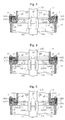
- Embodiment 3 of the invention will be explained in reference to Fig. 3 showing a still other example of an essential portion of a gas-insulated power apparatus as follows. Further, in Fig. 3 , portions the same as or corresponding to those of Fig. 1 , Fig. 2 are attached with the same notations and Embodiment 3 of the invention will be explained as follows with regard to a point different from those of Embodiments 1, 2 of the invention.
- Embodiment 1 of the invention in bringing the flange 111 of the vessel 11 on one side and the flange 121 of the vessel 12 on other side into press contact with each other, the two flanges 111, 121 are permitted to slide relative to each other in the peripheral direction, and the airtightness between the two flanges 111, 121 is maintained. Further, as described above, the grease coated at the portion of bringing the flange 111 of the vessel 11 on one side and the flange 121 of the vessel 12 on other side into press contact with each other maintains the airtightness between the two flanges 111, 121 further excellently. In order to maintain the airtightness further excellently, according to Embodiment 3 of the invention, one O ring 121R is arranged at the sliding face 1112 as exemplified in Fig. 3 .
- the O ring 121R is attached to the flange 121 of the vessel 12 on other side a wall thickness of which is thicker than that of the flange 111 of the vessel 11 on one side, and surrounds the power conductor 112 or 122, and the in-vessel power conductor connector 151.
- Embodiment 4 of the invention will be explained in reference to Fig. 4 showing a still other example of an essential portion of a gas-insulated power apparatus as follows. Further, in Fig. 4 , portions the same as or corresponding to those of Fig. 1 , Fig. 2 , Fig. 3 are attached with the same notations, and Embodiment 4 of the invention will be explained as follows mainly with regard to a point different from those of Embodiments 1, 2, 3 of the invention.
- Embodiment 3 of the invention in order to further improve the airtightness between the two flanges 111, 121, there is exemplified a case of arranging the one O ring 121R at the sliding face 1112, according to Embodiment 4 of the invention, as exemplified in Fig. 4 , a plurality of pieces of O rings 121R1, 121R2 are arranged at the sliding face 1112.
- the O ring 121R2 on an outer side concentrically surrounds the O ring 121R1 on an inner side.
- a plurality of pieces of O rings 121R1, 121R2 are concentrically arranged at the sliding face 1112, and therefore, the airtightness is further improved than in the case of arranging the one O ring 121R at the sliding face 1112.
- Embodiment 5 of the invention will be explained in reference to Fig. 5 showing a still other example of an essential portion of a gas-insulated power apparatus as follows. Further, in Fig. 5 , portions the same as or corresponding to those of Fig. 1 , Fig. 2 , Fig. 3, Fig. 4 are attached with the same notations, and Embodiment 5 of the invention will be explained as follows mainly with regard to a point different from those of Embodiments 1, 2, 3, 4 of the invention.
- Embodiment 5 of the invention is an example when the flange 111 which is squeezed is pivotably fitted to a fitting recess 1212 of the flange 121 which is squeezing.
- the squeezed flange 111 and the squeezing flange 121 are pivoted relative to each other at the surrounding of an axis center thereof for adjusting the swing angle or the like.
- Embodiment 5 of the invention the operability of the pivoting operation for the adjustment or the like (That is, integrating operation or the adjusting operation in installing at a cite or the like) is promoted, an integration accuracy, an installation adjustment accuracy or the like is promoted.
- Embodiment 6 is an example when the invention is applied to a case of connecting 3 phase buses and a bushing by a bushing lead out bus
- Fig. 6(a) is a plane view thereof
- Fig. 6(b) is a side view viewed from VIb-VIb line of Fig. 6 (a) in an arrow mark direction.
- Fig. 6 portions the same as or corresponding to those of Fig. 1 , Fig. 2 , Fig. 3, Fig. 4, Fig. 5 are attached with the same notations and Embodiment 6 of the invention will be explained mainly with regard to a point different from those of Embodiments 1, 2, 3, 4, 5 of the invention.
- a U phase gas-insulated bus UGIB and a V phase gas-insulated bus VGIB and a W phase gas-insulated bus WGIB which are respectively prolonged are laid at an installed location of a substation or the like to extend in parallel.
- a U phase bushing UBsg and a V phase bushing VBsg and a W phase bushing WBsg are provided to align to be spaced apart from each other by sufficient leakage distances.
- the U phase gas-insulated bus UGIB and the V phase gas-insulated bus VGIB and the W phase gas-insulated bus WGIB which are respectively prolonged are laid such that a direction of aligning the U phase bushing UBsg, the U phase bushing VBsg, the U phase bushing WBsg and the direction of extending the U phase gas-insulated bus UGIB and the V phase gas-insulated bus VGIB and the W phase gas-insulated bus WGIB constitute the same direction.
- the respective phase gas-insulated buses UGIB, VGIB, WGIB include bus conductors UB, VB, WB insulated by the gas 13.
- a front end OHTL of each of the U phase bushing UBsg, the V phase bushing VBsg, the W phase bushing WBsg is connected to an overhead transmission line or a transformer bushing.
- U phase gas-insulated bus UGIB and the U phase bushing UBsg are connected by way of a gas-insulted connection bus UGIBBB by a bushing lead out bus UGIBB of U phase constituting a gas-insulated bus.
- V phase gas-insulated bus VGIB and the V phase bushing VBsg are connected by way of a gas-insulated connection bus VGIBBB of V phase by a bushing lead out bus VGIBB of V phase constituting a gas-insulated bus
- W phase gas-insulated bus WGIB and the W phase bushing WBsg are connected by way of a gas-insulated connection bus WGIBBB by a bushing lead out bus WGIBB constituting a gas-insulated bus.
- the gas-insulated connection buses UGIBBB, VGIBBB, WGIBBB each includes the first vessel (the other vessel) 12, the connection vessel (the one vessel) 11, the pressing member 14, the flange 121 of the first vessel (the other vessel) 12, the flange 111 of the connection vessel (the one vessel) 11, and the bolt 17 exemplified in Figs.1 through 5 .
- the flanges 121 of respective U, V, W phases are coupled to be fixed to the gas-insulated buses UGIB, VGIB, WGIB of respective corresponding U, V, W phases by way of the corresponding first vessels (the other vessels) 12.
- the bushing lead out buses UGIBB, VGIBB, WGIBB of the respective phases correspond to the second vessels (branch pipe shape vessels) 16 exemplified in Figs.1 through 5 .
- Embodiment 6 similar to, for example, the case of Fig. 1 or Fig. 2 , before the other vessel (the first vessel) 12 is screwed to the flange 121 by the bolt 17, the other vessel (the first vessel) 12 and the flange 121 thereof can be pivoted around the one vessel 11 and the flange 111.
- the through hole 1411 of the pressing member 14 can easily be matched to the screw hole 1211 of the flange 121 of the other vessel 12, and the respective bolts 17 can easily and firmly be inserted to the respective through holes 1411 and screwed to the respective screw holes 1211. That is, integration or installation of various products can flexibly be dealt with without depending on only design of respective product specifications.
- a swing angle ⁇ c of the U phase bushing lead out bus UGIBB, a swing angle ⁇ b of the V phase bushing lead out bus VGIBB, and a swing angle ⁇ a of the W phase bushing lead out bus WGIBB differ between those in design and those in installation at an actual cite, as described above, before the other vessel (the first vessel) 12 is screwed to the flange 121 by the bolt 17, the other vessel (the first vessel) 12 and the flange 121 thereof can be pivoted around the one vessel 11 and the flange 111.
- the swing angles can easily be adjusted. Further, the adjustment can be carried out even after the other vessel (the first vessel) 12 is screwed to the flange 121 by the bolt 17, depending on the degree of the screwing.
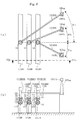
- Embodiment 7 is an example when the invention is applied to a connection between a prolonged first gas-insulated bus and a prolonged second gas-insulated bus
- Fig. 7 (a) is a plane view of the example
- Fig. 7(b) is a front view viewed from VIIb-VIIb line of Fig. 7(a) in an arrow mark direction
- Fig. 7(c) is a side view viewed from VIIc-VIIc line of Fig. 7(a) in an arrow mark direction.
- Fig. 7 portions the same as or corresponding to those of Fig. 1 , Fig. 2 , Fig. 3, Fig. 4, Fig. 5 , Fig. 6 are attached with the same notations and Embodiment 7 of the invention will be explained as follows mainly with regard to a point different from those of Embodiments 1, 2, 3, 4, 5, 6 of the invention.
- a prolonged first gas-insulated bus LGIB1 and a prolonged second gas-insulated bus LGIB2 are not arranged on the same axis line but arranged such that respective axis lines of the gas-insulated buses LGIB1, LGIB2 are shifted from each other.
- connection vessel GIBC intersects with directions of extending the first and the second gas-insulated buses LGIB1, LGIB2 in an extending direction thereof and integrally includes branch pipe shape vessels GIBC1, GIBC2 at both end portions of an outer periphery thereof.
- connection vessel GIBC includes end portion hermetically closing lids GIBC3, GIBC4 at both ends thereof.
- the end portion hermetically closing lids GIBC3, GIBC4 hermetically close inside of the connection vessel GIBC from outside.
- connection conductor GIBC5 insulated by the gas 13 at inside of the connection vessel GIBC is supported by the end portion hermetically closing lid GIBC3 by a column-like insulated support member GIBC6 at one end portion thereof and supported by the end portion hermetically closing lid GIBC4 by a column-like insulated support member GIBC7 at other end thereof.
- the one vessel 11, the pressing member 14, the flange 111 of the one vessel 11 and the like exemplified in Figs.1 through 5 are coupled to the flanges 121 by the bolts 17.
- the first and the second gas-insulated buses LGIB1, LGIB2 correspond to the second vessels (branch pipe shape vessels) 16 exemplified in Figs.1 through 5 and coupled to the corresponding vessels 11 on one side by way of the flanges LGIB11, LGIB21.
- the one vessel 11 and the flange 111 thereof can relatively be pivoted around the pressing member 14 and the flange 121 and the axis centers.
- the flange 121 and the pressing member 14 which are squeezing and the flange 111 which is squeezed are constituted by different metals, and a semi solid state lubricant of grease or the like is coated on the sliding face 1112 between the two flanges 111, 121 constituting portions at which the flange 111 and the flange 121 are brought into press contact with each other (refer to also Fig. 1(a) , Fig. 2(a) , Fig. 3 through Fig. 5 ).
- first gas-insulated bus LGIB1 and the prolonged second gas-insulated bus LGIB2 are prolonged, even when the buses are thermally elongated and contracted by a considerable amount by an environmental temperature change, according to the above-described constitution of Embodiment 7, thermal elongation and contraction of the first and the second gas-insulated buses LGIB1, LGIB2 can be absorbed by relatively pivoting the vessel 11 and the flange 111 and the pressing member 14 and the flange 121.
- Fig. 7 (a) when the first and the second gas-insulated buses LGIB1, LGIB2 are elongated in a direction of an arrow mark A by elevating an environmental temperature, while pivoting the vessel 11 and the flange 111 and the pressing member 14 and the flange 121 relative to each other as described above, the respective vessels 11, 11 in correspondence with the first and the second gas-insulated buses LGIB1, LGIB2, and the connection vessel GIBC are pivoted in an arrow mark B direction centering on a center O in a longitudinal direction thereof.
- bus connection device BCD having the above-described structure different from a bellows.
- the bus connection device BCD is a portion excluding the first and the second gas-insulated buses LGIB1, LGIB2 in Fig. 7 (a), Fig. 7(b), Fig. 7(c) .
- the contiguous vessels 11, GIBC are coupled by squeezing the flange 111 of the vessel 11 on one side to be coupled by the pressing member 14 screwed to the flange 121 of the vessel GIBC on other side and the flange 121 of the vessel GIBC on other side and the flange 121 of the vessel GIBC on other side.
- Embodiment 7 includes the first and the second vessels 11, 11 including the gas-insulated power conductors, and the connection vessel GIBC for connecting the first vessel 11 in correspondence with the first gas-insulated bus LGIB1 and the second vessel 11 in correspondence with the second gas-insulated bus LGIB2, and the first vessel 11 (in correspondence with the first gas-insulated bus LGIB1) and the connection vessel GIBC contiguous to each other are coupled and the second vessel 11 (in correspondence with the second gas-insulated bus LGIB2) and the connection vessel GIBC contiguous to each other are coupled by squeezing the flange 111 of the vessel 11 on one side to be coupled by the pressing member 14 screwed to the flange 121 of the vessel GIBC on other side to be coupled and the flange 121 of the vessel GIBC on other side.
- Embodiment 8 of the invention will be explained in reference to Fig. 8 showing an example of an essential portion of a gas-insulated power apparatus as follows. Further, in Fig. 8 , portions the same as or corresponding to those of Fig. 1 , Fig. 2 , Fig. 3, Fig. 4, Fig. 5 , Fig. 6 , Fig. 7 are attached with the same notations and Embodiment 8 of the invention will be explained as follows mainly with regard to a point different from those of Embodiments 1, 2, 3, 4, 5, 6, 7 of the invention.
- Embodiment 8 of the invention is an example in which in a gas-insulated power apparatus coupling the contiguous vessels 11, 12 by squeezing the flange 111 of the vessel 11 on one side to be coupled by the pressing member 14 screwed to the flange 121 of the vessel 12 on other side and the flange 121 of the vessel 12 on other side, the column-like insulating spacer 1131 is attached to the lower end portion hermetically closing lid 113 of the vessel 11 on one side, a bottom chamber 1132 surrounding a root portion of the column-like insulating spacer 1131 is formed and the bottom chamber 1132 is made to constitute a well-known particle trap.
- the particle trap is a portion of catching a particle of a metal small piece generated in integration and remaining at inside of the vessels 11, 12, 16, a contact metal powder scattered from a contact of the circuit breaker by operating the circuit breaker.
- the bottom chamber 1132 constituting the particle trap is formed to surround the root portion of the column-like insulated spacer 1131 attached to the lower end portion hermetically closing lid 113, and therefore, the bottom chamber 1132 can be disposed on a lower side of the branch pipe shape vessel 16, and therefore, the bottom chamber 1132 is disposed at a position on a lower side of an upper end portion or a middle portion of the column-like insulated spacer 1131 determined in relation to a position of the inner power conductor 161 of the branch pipe shape vessel 16. Therefore, the particle trap constituting the bottom chamber 1132 according to Embodiment 8 can effectively catch the particle without effecting an influence so much on an insulating function of the column-like insulating spacer 1131.
- Embodiment 9 is other example when the invention is applied to the case of connecting the 3 phase buses and a bushing by a bushing lead out bus
- Fig. 9(a) is a plane view thereof
- Fig. 9(b) is a side view viewing a portion surrounded by a one-dotted chain line of Fig. 9(a) from a VIb-VIb line in an arrow mark direction.
- Fig. 9 portions the same as or corresponding to those of Fig. 1 through Fig. 8 are attached with the same notations and Embodiment 9 of the invention will be explained as follows mainly with regard to a point different from those of Embodiments 1 through 8 of the invention.
- Embodiment 6 mentioned above is the example when the gas-insulated buses UGIB, VGIB, WGIB independent from each other in respective phases of U, V, W are laid, as exemplified in Fig. 9 , the example of Embodiment 9 is an example when a so-to-speak 3 phase summarized bus UVWGIB in which the bus conductors UB, VB, WB of respective phases of U, V, W are included in a common vessel is laid.
- the first vessels (the vessels on other side) 12, 12, 12 of respective phases U, V, W are coupled to top portions of a vessel UVWGIBC of the 3 phase summarized bus UVWGIB, and the respective vessels 12, 12, 12 of respective phases U, V, Ware disposed at the same height.
- a direction of aligning the first vessels (vessels on other side) 12, 12, 12 of respective phases U, V, W is in parallel with the direction of aligning the bushings UBsg, VBsg, WBsg of respective phases.
- the power conductor 122 at inside of the first vessel (the vessel on other side) 12 of U phase is connected to the bus conductor UB of U phase
- the power conductor 122 at inside of the first vessel (the vessel on other side) 12 of V phase is connected to the bus conductor VB of V phase
- the power conductor 122 at inside of the first vessel (the vessel on other side) 12 of W phase is connected to the bus conductor WB of W phase respectively at inside of the vessel UVWGIBC of the 3 phase summarized bus UVWGIB by way of tulip contacts or the like.
Landscapes
- Engineering & Computer Science (AREA)
- Power Engineering (AREA)
- Installation Of Bus-Bars (AREA)
- Gas-Insulated Switchgears (AREA)
Abstract
Description
- The present invention relates to a gas-insulated power apparatus in which contiguous vessels are coupled by way of flanges of respectives thereof and a power conductor insulated from the vessel by an insulating gas is included in the vessel.
- According to the gas-insulated apparatus of a gas-insulated opening/closing apparatus, a gas-insulated transformation apparatus, a gas-insulated bus or the like, a plurality of vessels are connected in airtight, and a power apparatus main body of a circuit breaker, a disconnecting switch, a grounding switch, a power conductor or the like is included in the hermetically closed vessel connected in airtight and enclosed with an insulating gas.
- According to the gas-insulated power apparatus, for example, a vessel of a gas-insulated bus led from the gas-insulated opening/closing apparatus or the like is coupled to a vessel of the gas-insulted opening/closing apparatus by fastening flange portions of respectives thereof by a bolt. Further, there is a case in which the led out gas-insulated bus is prolonged, and in this case, a bellows in series coupling is used for the vessel per se of the gas-insulated bus in order to absorb thermal elongation/contraction of the gas-insulated bus per se (for example, refer to Patent Reference 1).
- Patent Reference 1:
JP-A-2003-51440 Fig. 1 and explanation thereof) - Although according to the gas-insulated power apparatus, as described above, for example, the vessel of the gas-insulated bus led out from the gas-insulated opening/closing apparatus or the like is coupled with the vessel of the gas-insulated opening/closing apparatus by fastening the respective flanges by the bolt, a direction of leading out the gas-insulated bus (also referred to as angle swinging) is various depending on a product, and therefore, the vessel, the flange or the like is designed for each product specification. Further, there are needed a number of the bellows coupled in series with the vessel per se of the gas-insulated bus in order to absorb the thermal elongation/contraction of the gas-insulated bus per se when the gas-insulated bus is prolonged.
- Therefore, even when the direction of leading out the gas-insulated bus or the like (angle swinging) is various depending on the product, it is preferable when there is a mechanism having a degree of freedom capable of dealing therewith without depending on only the design for each product specification, and it is further preferable when the mechanism can be used as a substitute for the bellows.
- The invention has been carried out in view of the above-described actual situation, it is a principal object thereof to realize a mechanism having a degree of freedom capable of dealing therewith without depending only on a design for each product specification and it is other object thereof to realize a mechanism capable of being used as a substitute for the bellows.
- A gas-insulated power apparatus of the invention is a gas-insulated power apparatus in which contiguous vessels are coupled by way of flanges of respectives thereof and power conductors insulated from the vessels by an insulating gas are included in the vessels, wherein the contiguous vessels are coupled by squeezing a flange of the vessel on one side to be coupled by a pressing member screwed to a flange of the vessel on other side and a flange of the vessel on other side, and positions of the vessel on one side and the vessel on other side to be coupled relative to each other in a peripheral direction of the flange can be shifted.
- Further, a gas-insulated power apparatus according to the invention is a gas-insulated power apparatus comprising a first and a second vessel including power conductors insulated by a gas and a connection vessel for connecting the first and the second vessel, wherein at least one of coupling of the first vessel and the connection vessel contiguous to each other and coupling of the second vessel and the connection vessel contiguous to each other is carried out by squeezing a flange of the vessel on one side to be coupled by a pressing member screwed to a flange of the vessel on other side and a flange of the vessel on other side, and positions of the first vessel and the second vessel relative to each other can be permitted to change.
- According to the invention, in the gas-insulated power apparatus in which the contiguous vessels are coupled by way of the flanges of the respectives, and the power conductors insulated from the vessels by the insulating gas are included in the vessels, the contiguous vessels are coupled by squeezing the flange of the vessel on one side to be coupled by the pressing member screwed to the flange of the vessel on other side and the flange of the vessel on other side, and therefore, the positions of the vessel on one side and the vessel on other side to be coupled relative to each other in the peripheral direction of the flange can be shifted, and therefore, integration or installation of various products can flexibly be dealt with without depending only on design for respective product specifications.
- Further, according to the invention, there is provided the gas-insulated power apparatus comprising the first and the second vessels including the power conductors insulated by the gas and the connection vessel for connecting the first vessel and the second vessel, wherein at least one of coupling of the first vessel and the connection vessel contiguous to each other and coupling of the second vessel and the connection vessel contiguous to each other is carried out by squeezing the flange of the vessel on one side to be coupled by the pressing member screwed to the flange of the vessel on other side and the flange of the vessel on other side, and therefore, the positions of the first vessel and the second vessel relative to each other can be permitted to change, and therefore, integration or installation of various products can flexibly be dealt with without depending only on design for respective product specifications, further, the invention can be used as a substitute for a bellows. BEST MODE FOR CARRYING OUT THE INVENTION
-
Embodiment 1 of the invention will be explained in reference toFig. 1 as follows.Fig. 1 illustrates views showing an example of an essential portion of a gas-insulated power apparatus,Fig. 1(a) is a vertical sectional side view,Fig. 1(b) is a cross-sectional plane view viewing a section at a line Ib-Ib ofFig. 1(a) in an arrow mark direction. Further, inFig. 1 (a) and Fig. 1(b) , the same portion are attached with the same notations. - In
Fig. 1(a) and Fig. 1(b) , there is exemplified an example of a gas-insulatedpower apparatus 1 in whichcontiguous vessels flanges power conductors vessels insulating gas 13 are included in thecorresponding vessels contiguous vessels flange 111 of thevessel 11 on one side to be coupled by a pressingmember 14 screwed to theflange 121 of thevessel 12 on other side and theflange 121 of thevessel 12 on other side. - The
vessels respective flanges pressing member 14, a plurality ofpieces flanges - The
power conductors respective vessels coaxial power conductors power conductor connector 151 of a tulip contact or the like permitting thepower conductors power conductors - The
power conductors vessels vessels insulating spacer 1131 attached to an end portion hermetically closinglid 113 of the at least onevessel 11. - A branch
pipe shape vessel 16 is connected to the at least onevessel 11, thepower conductor 112 at inside of thevessel 11 is connected with apower conductor 161 at inside of the branchpipe shape vessel 16 by way of apower conductor connector 152 at inside of the branch pipe shape vessel permitting thepower conductor 161 at inside of the branchpipe shape vessel 16 to elongate and contract in an axial direction, and thepower conductor 161 at inside of the branchpipe shape vessel 16 is insulated from the branchpipe shape vessel 16 and thevessel 11 by the column-likeinsulating spacer 1131 for insulating thepower conductor 112 at inside of thevessel 11 from thevessel 11. - Further, when viewed by changing a view point, the gas-insulated apparatus according to
Embodiment 1 includes the first and thesecond vessels power conductors vessel 11 for connecting thefirst vessel 12 and thesecond vessel 16, and at least one of coupling of thefirst vessel 12 and the connectingvessel 11 contiguous to each other and coupling of thesecond vessel 16 and the connectingvessel 11 contiguous to each other is carried out by squeezing theflange 111 of thevessel 11 on one side to be coupled by the pressingmember 14 screwed to theflange 121 of thevessel 12 on other side and theflange 121 of thevessel 12 on other side. - All of the included
power conductors first vessel 12, thesecond vessel 16, and the connectingvessel 11 are insulated from thecorresponding vessels insulating spacer 1131 attached to the end portion hermetically closinglid 113 of thevessel 11. - By bringing the
flange 111 of thevessel 11 on one side and theflange 121 of thevessel 12 on other side into press contact with each other, the twoflanges flanges - The
flange 121 and thepressing member 14 which are squeezing and theflange 111 which is squeezed comprise different kinds of metals. Theflange 121 and thepressing member 14 which are squeezing comprise, for example, a ferrous conductive metal, and theflange 111 which is squeezed comprises, for example, an aluminum species conductive metal. When theflange 121 and thepressing member 14 which are squeezing and theflange 111 which is squeezed comprise different kinds of metals, burning at slidingfaces 1112 between the twoflanges flanges flange 111. - A semi solid state lubricant of grease or the like is coated at portions of the
flange 111 of thevessel 11 on one side and theflange 121 of thevessel 12 on other side brought into press contact with each other. The semi solid state lubricant coated at the portions of theflange 111 of thevessel 11 on one side and theflange 121 of thevessel 12 on other side brought into press contact with each other maintains the airtightness between the twoflanges - A lubrication layer of coating of, for example, almite plating, teflon (registered trademark) or the like may be applied to the portions of the
flange 111 of thevessel 11 on one side and theflange 121 of thevessel 12 on other side brought into press contact with each other. The lubrication layer applied to the portions brought into press contact with each other permits the twoflanges flanges flange 111 of thevessel 11 on one side by the pressingmember 14 screwed to theflange 121 of thevessel 12 on other side and theflange 121 of thevessel 12 on other side while maintaining the airtightness. - The respective pressing
members member 14 in the ring-like shape are screwed to theflange 121 of the vessel on other side (the first vessel) 12 by respectively by a plurality of pieces ofbolts 17. - The
bolts 17 penetrate the respective pressingmembers flange 121 of the vessel on other side (the first vessel) 12. That is, thebolts 17 penetrate bolt throughholes members holes 1211 constituting female screws provided at theflange 121 of the vessel on other side (the first vessel) 12. - The pressing
member 14 in the ring-like shape is constituted by the plurality of dividedpressing members pressing members flange 121 of the vessel on other side (which is also the first vessel) 12 attachably and detachably by the bolts (fastening members) 17. Owing to a structure of squeezing theflange 111 of the vessel on one side (which is also the connecting vessel) 11 by thepressing member 14 and theflange 121 of the vessel on other side (first vessel) 12 by such mounting operation, thepressing members contiguous vessels vessel 12, and a degree of freedom of design or installation of thevessels - When the relative positions in the peripheral direction of the
contiguous vessels vessel 12 is adjusted, thecontiguous vessels vessels power conductors power conductors power conductor connector 151 of a tulip contact or the like. - A gap g1 is formed between respective large diameter inner peripheral faces of the
pressing members flange 111 of thevessel 11 on one side, and the gap g1 permits thepressing members flange 111 of thevessel 11 on one side to thermally elongate and contract in diameter directions of respectives thereof. - Similarly, a gap g2 is formed between respective small diameter inner peripheral faces of the
pressing members vessel 11 on one side, and the gap g2 permits thepressing members vessel 11 on one side to thermally elongate and contract in diameter directions of respectives thereof. - Similarly, a gap g3 is formed between
respective end faces pressing members pressing members - The second vessel (which is also the branch pipe shape vessel) 16 is, for example, a gas-insulated connection conductor from a bushing lead out bus, an elongated gas-insulated bus, a gas-insulated switch to a feed line or the like.
- Embodiment 2 of the invention will be explained in reference to
Fig. 2 as follows.Fig. 2 illustrates views showing other example of an essential portion of a gas-insulated power apparatus,Fig. 2(a) is a vertical sectional side view,Fig. 2 (b) is a cross-sectional plane view viewing a section at a line IIb-IIb ofFig. 2(a) in an arrow mark direction. Further, inFig. 2(a) and Fig. 2(b) , portions the same as or corresponding to those ofFig. 1(a), Fig. 1(b) are attached with the same notations and Embodiment 2 of the invention will be explained as follows mainly of a point different from that ofEmbodiment 1 of the invention. - According to Embodiment 2 of the invention, as shown in
Fig. 2 (a) and Fig. 2 (b) thepressing member 14 is constituted by a shape of a continuous ring in correspondence with theflange 111 in the ring-like shape and is fitted to thevessel 11 on one side before integrally attaching theflange 111 to the vessel on one side (the connecting vessel) 11 by welding or the like.
In other words, thepressing member 14 according to Embodiment 2 of the invention is constituted not by the structure divided into a plurality of pieces as in thepressing member 14 ofEmbodiment 1 of the invention but by a continuous integrated structure. - Also in a case of Embodiment 2 of the invention, similar to the case of
Embodiment 1 of the invention, the gaps g1, g2 are provided, and therefore, even when thepressing member 14 is fitted to thevessel 11 on one side before integrally attaching theflange 111 to thevessel 11 on one side, similar to the case ofEmbodiment 1 of the invention, before the vessel on other side (the first vessel) 12 being screwed to theflange 121 by thebolt 17, the vessel on other side (the first vessel) 12 and theflange 121 thereof can be pivoted around thevessel 11 on one side and theflange 111. Therefore, even when the positions in the peripheral direction of the vessel on one side (the connecting vessel) 11 and the vessel on other side (the first vessel) 12 constituted by any positions, further, even when the swing angle of the second vessel (the branch pipe shape vessel) 16 relative to the vessel on other side (the first vessel) 12 is constituted by any angle, the throughhole bolt 1411 of thepressing member 14 can easily be matched to thescrew hole 1211 of theflange 121 of thevessel 12 on other side, and therespective bolts 17 can easily and firmly be inserted to the respective bolt throughholes 1411 and screwed to therespective screw holes 1211. That is, the invention can flexibly deal with integration or installation of various products without depending on only design of respective product specifications. - Embodiment 3 of the invention will be explained in reference to
Fig. 3 showing a still other example of an essential portion of a gas-insulated power apparatus as follows. Further, inFig. 3 , portions the same as or corresponding to those ofFig. 1 ,Fig. 2 are attached with the same notations and Embodiment 3 of the invention will be explained as follows with regard to a point different from those ofEmbodiments 1, 2 of the invention. - In
Embodiment 1 of the invention, as described above, in bringing theflange 111 of thevessel 11 on one side and theflange 121 of thevessel 12 on other side into press contact with each other, the twoflanges flanges flange 111 of thevessel 11 on one side and theflange 121 of thevessel 12 on other side into press contact with each other maintains the airtightness between the twoflanges O ring 121R is arranged at the slidingface 1112 as exemplified inFig. 3 . - The
O ring 121R is attached to theflange 121 of thevessel 12 on other side a wall thickness of which is thicker than that of theflange 111 of thevessel 11 on one side, and surrounds thepower conductor power conductor connector 151. -
Embodiment 4 of the invention will be explained in reference toFig. 4 showing a still other example of an essential portion of a gas-insulated power apparatus as follows. Further, inFig. 4 , portions the same as or corresponding to those ofFig. 1 ,Fig. 2 ,Fig. 3 are attached with the same notations, andEmbodiment 4 of the invention will be explained as follows mainly with regard to a point different from those ofEmbodiments 1, 2, 3 of the invention. - Although in Embodiment 3 of the invention, in order to further improve the airtightness between the two
flanges O ring 121R at the slidingface 1112, according toEmbodiment 4 of the invention, as exemplified inFig. 4 , a plurality of pieces of O rings 121R1, 121R2 are arranged at the slidingface 1112. The O ring 121R2 on an outer side concentrically surrounds the O ring 121R1 on an inner side. - A plurality of pieces of O rings 121R1, 121R2 are concentrically arranged at the sliding
face 1112, and therefore, the airtightness is further improved than in the case of arranging the oneO ring 121R at the slidingface 1112. - Embodiment 5 of the invention will be explained in reference to
Fig. 5 showing a still other example of an essential portion of a gas-insulated power apparatus as follows. Further, inFig. 5 , portions the same as or corresponding to those ofFig. 1 ,Fig. 2 ,Fig. 3, Fig. 4 are attached with the same notations, and Embodiment 5 of the invention will be explained as follows mainly with regard to a point different from those ofEmbodiments - As shown by
Fig. 5 , Embodiment 5 of the invention is an example when theflange 111 which is squeezed is pivotably fitted to afitting recess 1212 of theflange 121 which is squeezing. - The squeezed
flange 111 and the squeezingflange 121 are pivoted relative to each other at the surrounding of an axis center thereof for adjusting the swing angle or the like. - When the squeezed
flange 111 is not pivotably fitted to thefitting recess 1212 of the squeezingflange 121, it is necessary to carry out the pivoting operation for the adjustment or the like (that is, an integrating operation or an adjusting operation in installing at a cite) while paying careful attention such that the twoflanges power conductors power conductor connector 151 owing to a relative shift in the diameter direction of thepower conductors flanges - In contrast thereto, when the squeezed
flange 111 is pivotably fitted to thefitting recess 1212 of the squeezingflange 121, in the pivoting for the adjustment or the like, the twoflanges
Therefore, there is not brought about a contact failure between thepower conductors power conductor connector 151 owing to the relative shift in the diameter direction of thepower conductors flanges
Therefore, it is not necessary to carry out the pivoting operation for the adjustment or the like (that is, the integrating operation or the adjusting operation in installing at a cite) while paying careful attention such that the twoflanges - In this way, according to Embodiment 5 of the invention, the operability of the pivoting operation for the adjustment or the like (That is, integrating operation or the adjusting operation in installing at a cite or the like) is promoted, an integration accuracy, an installation adjustment accuracy or the like is promoted.
- Embodiment 6 is an example when the invention is applied to a case of connecting 3 phase buses and a bushing by a bushing lead out bus,
Fig. 6(a) is a plane view thereof,Fig. 6(b) is a side view viewed from VIb-VIb line ofFig. 6 (a) in an arrow mark direction. Further, inFig. 6 , portions the same as or corresponding to those ofFig. 1 ,Fig. 2 ,Fig. 3, Fig. 4, Fig. 5 are attached with the same notations and Embodiment 6 of the invention will be explained mainly with regard to a point different from those ofEmbodiments - In
Figs.6(a), (b) , a U phase gas-insulated bus UGIB and a V phase gas-insulated bus VGIB and a W phase gas-insulated bus WGIB which are respectively prolonged are laid at an installed location of a substation or the like to extend in parallel. - Further, a U phase bushing UBsg and a V phase bushing VBsg and a W phase bushing WBsg are provided to align to be spaced apart from each other by sufficient leakage distances.
- The U phase gas-insulated bus UGIB and the V phase gas-insulated bus VGIB and the W phase gas-insulated bus WGIB which are respectively prolonged are laid such that a direction of aligning the U phase bushing UBsg, the U phase bushing VBsg, the U phase bushing WBsg and the direction of extending the U phase gas-insulated bus UGIB and the V phase gas-insulated bus VGIB and the W phase gas-insulated bus WGIB constitute the same direction. Further, the respective phase gas-insulated buses UGIB, VGIB, WGIB include bus conductors UB, VB, WB insulated by the
gas 13. - Further, a front end OHTL of each of the U phase bushing UBsg, the V phase bushing VBsg, the W phase bushing WBsg is connected to an overhead transmission line or a transformer bushing.
- Further, the U phase gas-insulated bus UGIB and the U phase bushing UBsg are connected by way of a gas-insulted connection bus UGIBBB by a bushing lead out bus UGIBB of U phase constituting a gas-insulated bus.
- Similarly, the V phase gas-insulated bus VGIB and the V phase bushing VBsg are connected by way of a gas-insulated connection bus VGIBBB of V phase by a bushing lead out bus VGIBB of V phase constituting a gas-insulated bus, and the W phase gas-insulated bus WGIB and the W phase bushing WBsg are connected by way of a gas-insulated connection bus WGIBBB by a bushing lead out bus WGIBB constituting a gas-insulated bus.
- The gas-insulated connection buses UGIBBB, VGIBBB, WGIBBB each includes the first vessel (the other vessel) 12, the connection vessel (the one vessel) 11, the pressing
member 14, theflange 121 of the first vessel (the other vessel) 12, theflange 111 of the connection vessel (the one vessel) 11, and thebolt 17 exemplified inFigs.1 through 5 .
Theflanges 121 of respective U, V, W phases are coupled to be fixed to the gas-insulated buses UGIB, VGIB, WGIB of respective corresponding U, V, W phases by way of the corresponding first vessels (the other vessels) 12. - The bushing lead out buses UGIBB, VGIBB, WGIBB of the respective phases correspond to the second vessels (branch pipe shape vessels) 16 exemplified in
Figs.1 through 5 . - Also in Embodiment 6, similar to, for example, the case of
Fig. 1 orFig. 2 , before the other vessel (the first vessel) 12 is screwed to theflange 121 by thebolt 17, the other vessel (the first vessel) 12 and theflange 121 thereof can be pivoted around theone vessel 11 and theflange 111. Therefore, even when the relative positions of the one vessel (the connection vessel) 11 and the other vessel (the first vessel) 12 in the peripheral direction are constituted by any positions, further, even when the swing angle of the second vessel (the branch pipe shape vessel) 16 relative to the other vessel (the first vessel) 12 is constituted by any angle, the throughhole 1411 of the pressingmember 14 can easily be matched to thescrew hole 1211 of theflange 121 of theother vessel 12, and therespective bolts 17 can easily and firmly be inserted to the respective throughholes 1411 and screwed to the respective screw holes 1211. That is, integration or installation of various products can flexibly be dealt with without depending on only design of respective product specifications. - For example, when a swing angle θc of the U phase bushing lead out bus UGIBB, a swing angle θb of the V phase bushing lead out bus VGIBB, and a swing angle θa of the W phase bushing lead out bus WGIBB differ between those in design and those in installation at an actual cite, as described above, before the other vessel (the first vessel) 12 is screwed to the
flange 121 by thebolt 17, the other vessel (the first vessel) 12 and theflange 121 thereof can be pivoted around theone vessel 11 and theflange 111. Therefore, even when the swing angle θc of the U phase bushing lead out bus UGIBB, the swing angle θb of the V phase bushing lead out bus VGIBB, and the swing angle θa of the W phase bushing lead out bus WGIBB differ from respective angles in design in installation at the actual cite, the swing angles can easily be adjusted. Further, the adjustment can be carried out even after the other vessel (the first vessel) 12 is screwed to theflange 121 by thebolt 17, depending on the degree of the screwing. -
Embodiment 7 is an example when the invention is applied to a connection between a prolonged first gas-insulated bus and a prolonged second gas-insulated bus,Fig. 7 (a) is a plane view of the example,Fig. 7(b) is a front view viewed from VIIb-VIIb line ofFig. 7(a) in an arrow mark direction,Fig. 7(c) is a side view viewed from VIIc-VIIc line ofFig. 7(a) in an arrow mark direction. Further, inFig. 7 , portions the same as or corresponding to those ofFig. 1 ,Fig. 2 ,Fig. 3, Fig. 4, Fig. 5 ,Fig. 6 are attached with the same notations andEmbodiment 7 of the invention will be explained as follows mainly with regard to a point different from those ofEmbodiments - According to
Embodiment 7 of the invention, as shown byFig. 7 , a prolonged first gas-insulated bus LGIB1 and a prolonged second gas-insulated bus LGIB2 are not arranged on the same axis line but arranged such that respective axis lines of the gas-insulated buses LGIB1, LGIB2 are shifted from each other. - A connection vessel GIBC intersects with directions of extending the first and the second gas-insulated buses LGIB1, LGIB2 in an extending direction thereof and integrally includes branch pipe shape vessels GIBC1, GIBC2 at both end portions of an outer periphery thereof.
- The connection vessel GIBC includes end portion hermetically closing lids GIBC3, GIBC4 at both ends thereof. The end portion hermetically closing lids GIBC3, GIBC4 hermetically close inside of the connection vessel GIBC from outside.
- A connection conductor GIBC5 insulated by the
gas 13 at inside of the connection vessel GIBC is supported by the end portion hermetically closing lid GIBC3 by a column-like insulated support member GIBC6 at one end portion thereof and supported by the end portion hermetically closing lid GIBC4 by a column-like insulated support member GIBC7 at other end thereof. - In either of the branch pipe shape vessels GIBC1, GIBC2, the one
vessel 11, the pressingmember 14, theflange 111 of the onevessel 11 and the like exemplified inFigs.1 through 5 are coupled to theflanges 121 by thebolts 17. - The first and the second gas-insulated buses LGIB1, LGIB2 correspond to the second vessels (branch pipe shape vessels) 16 exemplified in
Figs.1 through 5 and coupled to the correspondingvessels 11 on one side by way of the flanges LGIB11, LGIB21. - As has been explained in reference to
Figs.1 through 6 , the onevessel 11 and theflange 111 thereof can relatively be pivoted around the pressingmember 14 and theflange 121 and the axis centers. Particularly, as described in paragraph Nos. [0021], [0022], theflange 121 and the pressingmember 14 which are squeezing and theflange 111 which is squeezed are constituted by different metals, and a semi solid state lubricant of grease or the like is coated on the slidingface 1112 between the twoflanges flange 111 and theflange 121 are brought into press contact with each other (refer to alsoFig. 1(a) ,Fig. 2(a) ,Fig. 3 through Fig. 5 ). - Since the prolonged first gas-insulated bus LGIB1 and the prolonged second gas-insulated bus LGIB2 are prolonged, even when the buses are thermally elongated and contracted by a considerable amount by an environmental temperature change, according to the above-described constitution of
Embodiment 7, thermal elongation and contraction of the first and the second gas-insulated buses LGIB1, LGIB2 can be absorbed by relatively pivoting thevessel 11 and theflange 111 and the pressingmember 14 and theflange 121. - For example, as exemplified in
Fig. 7 (a) , when the first and the second gas-insulated buses LGIB1, LGIB2 are elongated in a direction of an arrow mark A by elevating an environmental temperature, while pivoting thevessel 11 and theflange 111 and the pressingmember 14 and theflange 121 relative to each other as described above, therespective vessels
When the first and the second gas-insulated buses LGIB1, LGIB2 are contracted in a direction reverse to the arrow mark A by lowering the environmental temperature, thevessel 11 and theflange 111 and the pressingmember 14 and theflange 121 are pivoted relative to each other in a direction reverse to that of the case of elevating the temperature, therespective vessels - In this way, thermal elongation and contraction of the prolonged first and second gas-insulated buses LGIB1, LGIB2 can be absorbed by a bus connection device BCD having the above-described structure different from a bellows. Further, the bus connection device BCD is a portion excluding the first and the second gas-insulated buses LGIB1, LGIB2 in
Fig. 7 (a), Fig. 7(b), Fig. 7(c) . - As described above, according to
Embodiment 7, in the gas-insulated power apparatus in which thevessel 11, GIBC contiguous to each other are coupled by way of theflanges power conductors 122, GIBC5 insulated from thevessel 11, GIBC by the insulatinggas 13 are included in thevessels 11, GIBC, thecontiguous vessels 11, GIBC are coupled by squeezing theflange 111 of thevessel 11 on one side to be coupled by the pressingmember 14 screwed to theflange 121 of the vessel GIBC on other side and theflange 121 of the vessel GIBC on other side and theflange 121 of the vessel GIBC on other side. - Further, in other words,
Embodiment 7 includes the first and thesecond vessels first vessel 11 in correspondence with the first gas-insulated bus LGIB1 and thesecond vessel 11 in correspondence with the second gas-insulated bus LGIB2, and the first vessel 11 (in correspondence with the first gas-insulated bus LGIB1) and the connection vessel GIBC contiguous to each other are coupled and the second vessel 11 (in correspondence with the second gas-insulated bus LGIB2) and the connection vessel GIBC contiguous to each other are coupled by squeezing theflange 111 of thevessel 11 on one side to be coupled by the pressingmember 14 screwed to theflange 121 of the vessel GIBC on other side to be coupled and theflange 121 of the vessel GIBC on other side. - Embodiment 8 of the invention will be explained in reference to
Fig. 8 showing an example of an essential portion of a gas-insulated power apparatus as follows. Further, inFig. 8 , portions the same as or corresponding to those ofFig. 1 ,Fig. 2 ,Fig. 3, Fig. 4, Fig. 5 ,Fig. 6 ,Fig. 7 are attached with the same notations and Embodiment 8 of the invention will be explained as follows mainly with regard to a point different from those ofEmbodiments - As shown by
Fig. 8 , Embodiment 8 of the invention is an example in which in a gas-insulated power apparatus coupling thecontiguous vessels flange 111 of thevessel 11 on one side to be coupled by the pressingmember 14 screwed to theflange 121 of thevessel 12 on other side and theflange 121 of thevessel 12 on other side, the column-like insulatingspacer 1131 is attached to the lower end portion hermetically closinglid 113 of thevessel 11 on one side, abottom chamber 1132 surrounding a root portion of the column-like insulatingspacer 1131 is formed and thebottom chamber 1132 is made to constitute a well-known particle trap. - As is well known, the particle trap is a portion of catching a particle of a metal small piece generated in integration and remaining at inside of the
vessels - According to Embodiment 8, the
bottom chamber 1132 constituting the particle trap is formed to surround the root portion of the column-likeinsulated spacer 1131 attached to the lower end portion hermetically closinglid 113, and therefore, thebottom chamber 1132 can be disposed on a lower side of the branchpipe shape vessel 16, and therefore, thebottom chamber 1132 is disposed at a position on a lower side of an upper end portion or a middle portion of the column-likeinsulated spacer 1131 determined in relation to a position of theinner power conductor 161 of the branchpipe shape vessel 16. Therefore, the particle trap constituting thebottom chamber 1132 according to Embodiment 8 can effectively catch the particle without effecting an influence so much on an insulating function of the column-like insulatingspacer 1131. - Embodiment 9 is other example when the invention is applied to the case of connecting the 3 phase buses and a bushing by a bushing lead out bus,
Fig. 9(a) is a plane view thereof andFig. 9(b) is a side view viewing a portion surrounded by a one-dotted chain line ofFig. 9(a) from a VIb-VIb line in an arrow mark direction. Further, inFig. 9 , portions the same as or corresponding to those ofFig. 1 through Fig. 8 are attached with the same notations and Embodiment 9 of the invention will be explained as follows mainly with regard to a point different from those ofEmbodiments 1 through 8 of the invention. - Although Embodiment 6 mentioned above is the example when the gas-insulated buses UGIB, VGIB, WGIB independent from each other in respective phases of U, V, W are laid, as exemplified in
Fig. 9 , the example of Embodiment 9 is an example when a so-to-speak 3 phase summarized bus UVWGIB in which the bus conductors UB, VB, WB of respective phases of U, V, W are included in a common vessel is laid. - According to Embodiment 9, the first vessels (the vessels on other side) 12, 12, 12 of respective phases U, V, W are coupled to top portions of a vessel UVWGIBC of the 3 phase summarized bus UVWGIB, and the
respective vessels - The
power conductor 122 at inside of the first vessel (the vessel on other side) 12 of U phase is connected to the bus conductor UB of U phase, thepower conductor 122 at inside of the first vessel (the vessel on other side) 12 of V phase is connected to the bus conductor VB of V phase, thepower conductor 122 at inside of the first vessel (the vessel on other side) 12 of W phase is connected to the bus conductor WB of W phase respectively at inside of the vessel UVWGIBC of the 3 phase summarized bus UVWGIB by way of tulip contacts or the like. - Owing to the structure, when the invention is applied to a case of connecting the 3 phase summarized bus and the bushing by the bushing lead out bus, an effect the same as that of Embodiment 6 is achieved by a simple structure.
-
- [
Fig. 1 ]
Fig. 1 illustratesviews showing Embodiment 1 of the invention and views showing a case of an essential portion of a gas-insulated power apparatus,Fig. 1(a) is a vertical sectional side view,Fig. 1(b) is a cross-sectional plane view viewing a section at Ib-Ib line ofFig. 1(a) in an arrow mark direction. - [
Fig. 2 ]
Fig. 2 illustrates views showing Embodiment 2 of the invention and views showing other case of an essential portion of a gas-insulated power apparatus,Fig. 2(a) is a vertical sectional side view,Fig. 2 (b) is a cross-sectional plane view viewing a section at IIb-IIb line ofFig. 2 (a) in an arrow mark direction. - [
Fig. 3 ]
Fig. 3 is a view showing Embodiment 3 of the invention and a view showing still other case of an essential portion of a gas-insulated power apparatus. - [
Fig. 4 ]
Fig. 4 is aview showing Embodiment 4 of the invention and a view showing still other case of an essential portion of a gas-insulated power apparatus. - [
Fig. 5 ]
Fig. 5 is a view showing Embodiment 5 of the invention and a view showing still other case of an essential portion of a gas-insulated power apparatus. - [
Fig. 6 ]
Fig. 6 illustrates views showing Embodiment 6 of the invention showing a case when the invention is applied to a case of connecting 3 phase buses and a bushing by a bushing lead out bus,Fig. 6 (a) is a plane view thereof,Fig. 6 (b) is a side view viewed from VIb-VIb line ofFig. 6 (a) in an arrow mark direction. - [
Fig. 7 ]
Fig. 7 illustratesviews showing Embodiment 7 of the invention showing a case when the invention is applied to a case of connection of a prolonged first gas-insulated bus and a prolonged second gas-insulated bus,Fig. 7 (a) is a plane view of the case,Fig. 7(b) is a front view viewed from VIIb-VIIb line ofFig. 7(a) in an arrow mark direction,Fig. 7(c) is a side view viewed from a VIIc-VIIc line ofFig. 7 (a) in an arrow mark direction. - [
Fig. 8 ]
Fig. 8 is a view showing Embodiment 8 of the invention and a view showing a case of an essential portion of a gas-insulated power apparatus. - [
Fig. 9 ]
Fig. 9 illustrates views showing Embodiment 9 of the invention showing other case when the invention is applied to a case of connecting 3 phase buses and a bushing by a bushing lead out bus,Fig. 9(a) is a plane view thereof.Fig. 9(b) is a side view viewing a portion surrounded by a one-dotted chain line ofFig. 9 (a) from VIb-VIb line in an arrow mark direction. -
- 11, 12 contiguous vessels
- 111, 121 flanges
- 1112 sliding face
- 112 power conductor
- 113 end portion hermetically closing lid
- 1131 column-like insulated spacer
- 1132 bottom chamber (particle trap)
- 1211 screw hole
- 121R, 121R1, 121R2 O rings
- 1212 fitting recess
- 122 power conductor
- 13 insulating gas
- 14, 141, 142 pressing members
- 1411, 1421 bolt through holes
- 1412, 1422 end faces of pressing members
- 151 in-vessel power conductor connector
- 152 power conductor connector in branch tube shape vessel
- 16 branch tube shape vessel
- 161 power conductor
- 17 bolt
- g1, g2, g3 gaps
- UB U phase bus conductor
- VB V phase bus conductor
- WB W phase bus conductor
- GIBC connection vessel
- GIBC1, GIBC2 branch tube shape vessels
- GIBC6, GIBC7
- GIBC3, GIBC4 end portion hermetically closing lids
- GIBC5 connection conductor
- GIBC6, GIBC7 column-like insulated support members
- LGIB1 prolonged first gas-insulated bus
- LGIB2 prolonged second gas-insulated bus
- LGIB11, LGIB21 flanges
- UVWGIB 3 phase summarized bus
- UVWGIBC vessel
- UGIB U phase gas-insulated bus
- UGIBB bushing lead out bus of U phase
- UGIBBB U phase gas-insulated connection bus
- VGIB V phase gas-insulated bus
- VGIBB bushing lead out bus of V phase
- VGIBBB V phase gas-insulated connection bus
- WGIB W phase gas-insulated bus
- WGIBB bushing lead out bus of W phase
- WGIBBB W phase gas-insulated connection bus
- UBsg U phase busing
- VBsg V phase bushing
- WBsg W phase bushing
- θa, θb, θc swing angles
Claims (17)
- A gas-insulated power apparatus characterized in a gas-insulated power apparatus in which contiguous vessels are coupled by way of flanges of respectives thereof and power conductors insulated from the vessels by an insulating gas are included in the vessels, wherein the contiguous vessels are coupled by squeezing a flange of the vessel on one side to be coupled by a pressing member screwed to a flange of the vessel on other side and the flange of the vessel on other side.
- The gas-insulated power apparatus according to Claim 1, characterized in that the vessel is constituted by a tube-like shape and the flange is constituted by a ring-like shape, and a plurality of pieces of the pressing members are arranged in a ring-like shape along the flange in the ring-like shape.
- The gas-insulated power apparatus according to Claim 1, characterized in that the vessel is constituted by a tube-like shape and the flange is constituted by a ring-like shape, and the pressing member is constituted by a shape of a continuous ring in correspondence with the flange in the ring-like shape and is fitted to the vessel before attaching the flange to the vessel.
- The gas-insulated power apparatus according to any one of Claims 1 through 3, characterized in that the squeezed flange is fitted pivotably to a fitting recess of the squeezing flange.
- The gas-insulated power apparatus according to any one of Claims 1 through 4, characterized in that the power conductors at inside of the respective vessels are coaxially arranged, the coaxial power conductors are connected by an in-vessel power conductor connector permitting the power conductors to elongate and contract in an axial direction and permitting the power conductors to pivot in a peripheral direction.
- The gas-insulated power apparatus according to any one of Claims 1 through 4, characterized in that the power conductor at inside of the vessel is insulated from the vessel by a column-like insulated spacer attached to an end portion hermetically closing lid of at least one of the vessel.
- The gas-insulated power apparatus according to Claim 6, characterized in that a branch tube shape vessel is connected to the at least one vessel;
wherein the power conductor at inside of the branch tube shape vessel is connected to the power conductor at inside of the vessel by way of a power conductor connector at inside of the branch tube shape vessel permitting the power conductor at inside of the branch tube shape vessel to elongate and contract in an axial direction;
wherein the power conductor at inside of the branch tube shape vessel is insulated from the branch tube shape vessel and the vessel by the column-like insulated spacer for insulating the power conductor at inside of the vessel from the vessel. - The gas-insulated power apparatus according to Claim 6, characterized in that a particle trap is constituted by attaching the column-like insulated spacer to a lower end portion hermetically closing lid of the vessel.
- A gas-insulated power apparatus comprising a first and a second vessel including power conductors insulated by a gas and a connection vessel for connecting the first and the second vessel, wherein at least one of coupling of the first vessel and the connection vessel contiguous to each other and coupling of the second vessel and the connection vessel contiguous to each other is carried out by squeezing a flange of the vessel on one side to be coupled by a pressing member screwed to a flange of the vessel on other side and the flange of the vessel on other side.
- The gas-insulated power apparatus according to Claim 9,
characterized in that the vessel is constituted by a tube-like shape and the flange is constituted by a ring-like shape, and a plurality of pieces of the pressing members are arranged in a ring-like shape along the flange in the ring-like shape. - The gas-insulated power apparatus according to Claim 9, characterized in that the vessel is constituted by a tube-like shape and the flange is constituted by a ring-like shape and the pressing member is constituted by a shape of a continuous ring in correspondence with the flange in the ring-like shape and is fitted to the vessel before attaching the flange to the vessel.
- The gas-insulated power apparatus according to any one of Claims 9 through 11, characterized in that the squeezed flange is pivotably fitted to a fitting recess of the squeezing flange.
- The gas-insulated power apparatus according to any one of Claims 9 through 12, characterized in that all of the respective power conductors included in the first vessel, the second vessel, and the connection vessel are insulated from the corresponding vessels by a column-like insulated spacer attached to an end portion hermetically closing lid of the vessel.
- The gas-insulated power apparatus according to any one of Claims 9 through 13, characterized in that by bringing the flange of the vessel on one side and the flange of the vessel on other side into press contact with each other, the two flanges are permitted to slide relative to each other in a peripheral direction and an airtightness between the two flanges is maintained.
- The gas-insulated power apparatus according to Claim 14, characterized in that a lubrication layer is applied to a portion of bringing the flange of the vessel on one side and the flange of the vessel on other side into press contact with each other.
- The gas-insulated power apparatus according to Claim 14, characterized in that at least one of embedding an O ring and coating a grease is carried out at the portion of bringing the flange of the vessel on one side and the flange of the vessel on other side into press contact with each other.
- The gas-insulated power apparatus according to any one of Claims 9 through 13, characterized in that the flange and the pressing member which are squeezing and the flange which is squeezed comprise different metals.
Applications Claiming Priority (1)
| Application Number | Priority Date | Filing Date | Title |
|---|---|---|---|
| PCT/JP2006/306883 WO2007116480A1 (en) | 2006-03-31 | 2006-03-31 | Gas-insulated electric power apparatus |
Publications (3)
| Publication Number | Publication Date |
|---|---|
| EP2003756A1 true EP2003756A1 (en) | 2008-12-17 |
| EP2003756A4 EP2003756A4 (en) | 2011-11-23 |
| EP2003756B1 EP2003756B1 (en) | 2018-04-25 |
Family
ID=38580789
Family Applications (1)
| Application Number | Title | Priority Date | Filing Date |
|---|---|---|---|
| EP06730831.2A Ceased EP2003756B1 (en) | 2006-03-31 | 2006-03-31 | Gas-insulated electric power apparatus |
Country Status (5)
| Country | Link |
|---|---|
| US (1) | US8519293B2 (en) |
| EP (1) | EP2003756B1 (en) |
| JP (1) | JP4940230B2 (en) |
| CN (1) | CN101496246B (en) |
| WO (1) | WO2007116480A1 (en) |
Cited By (1)
| Publication number | Priority date | Publication date | Assignee | Title |
|---|---|---|---|---|
| WO2012110356A1 (en) * | 2011-02-14 | 2012-08-23 | Siemens Aktiengesellschaft | Extendable-length encapsulating housing arrangement for an encapsulated electrical energy transmission device |
Families Citing this family (7)
| Publication number | Priority date | Publication date | Assignee | Title |
|---|---|---|---|---|
| JP5523903B2 (en) * | 2010-04-07 | 2014-06-18 | 株式会社東芝 | Gas insulated bus |
| WO2012066614A1 (en) * | 2010-11-15 | 2012-05-24 | 三菱電機株式会社 | Gas insulated busbar |
| JP4781493B1 (en) | 2011-02-28 | 2011-09-28 | 三菱電機株式会社 | Gas insulated bus |
| US9530594B2 (en) * | 2014-04-24 | 2016-12-27 | Abb Schweiz Ag | Integrated particle trap in a tank of a dead tank circuit breaker |
| WO2017162533A1 (en) * | 2016-03-24 | 2017-09-28 | Abb Schweiz Ag | Electrical circuit breaker device with particle trap |
| CN106410656B (en) * | 2016-06-28 | 2018-08-14 | 湖南长高电气有限公司 | A kind of turn conductor of Cubicle Gas-Insulated Switchgear |
| JPWO2025041199A1 (en) * | 2023-08-18 | 2025-02-27 |
Family Cites Families (26)
| Publication number | Priority date | Publication date | Assignee | Title |
|---|---|---|---|---|
| DE1927784A1 (en) * | 1969-05-30 | 1970-12-03 | Siemens Ag | Metal-enclosed high-voltage switchgear |
| JPS507739B1 (en) | 1969-12-17 | 1975-03-28 | ||
| JPS5148269B2 (en) * | 1971-12-22 | 1976-12-20 | ||
| US4079746A (en) | 1975-12-24 | 1978-03-21 | Keystone International, Inc. | Valve assembly having adapter means |
| JPS5297431U (en) * | 1976-01-20 | 1977-07-21 | ||
| JPS53111273A (en) * | 1977-03-09 | 1978-09-28 | Matsushita Electronics Corp | Mamufacture of magnetron anode |
| JPS589479Y2 (en) | 1978-06-05 | 1983-02-21 | 日新電機株式会社 | Pipeline aerial power transmission line connection device |
| DE3011657C2 (en) * | 1980-03-26 | 1982-05-27 | Eumuco Aktiengesellschaft für Maschinenbau, 5090 Leverkusen | Device for carrying out the change of shear blades on scissors and the like. |
| JPS6111950Y2 (en) | 1980-04-16 | 1986-04-15 | ||
| JPS6349044Y2 (en) | 1981-03-25 | 1988-12-16 | ||
| JPS59183582A (en) * | 1983-04-04 | 1984-10-18 | Konishiroku Photo Ind Co Ltd | Electronic still camera |
| JPS619112A (en) * | 1984-06-20 | 1986-01-16 | 三菱電機株式会社 | Electric insulator |
| JPH033122U (en) | 1989-01-31 | 1991-01-14 | ||
| JPH033122A (en) * | 1989-05-31 | 1991-01-09 | Toshiba Corp | Focus detector |
| DE4318074A1 (en) | 1993-06-01 | 1994-12-08 | Abb Patent Gmbh | Enclosed gas-insulated switchgear with cable termination |
| JPH09126321A (en) * | 1995-10-30 | 1997-05-13 | Haniyuuda Tekko:Kk | Seal structure or pressure vessel lid |
| JPH1047483A (en) * | 1996-08-06 | 1998-02-20 | Haniyuuda Tekko:Kk | Pressure-vessel seal structure |
| DE29614799U1 (en) * | 1996-08-13 | 1996-10-24 | Siemens AG, 80333 München | High voltage switchgear |
| JPH10172372A (en) | 1996-12-13 | 1998-06-26 | Hitachi Ltd | Current-carrying conductor contacts |
| JP3432407B2 (en) * | 1998-01-21 | 2003-08-04 | 三菱電機株式会社 | Gas insulated switchgear and transformer connection device |
| JPH11218220A (en) * | 1998-02-03 | 1999-08-10 | Hanyuda Tekko:Kk | Seal structure of pressure container |
| JP2002051440A (en) | 2000-07-31 | 2002-02-15 | Sumitomo Electric Ind Ltd | Stretch absorbing structure and method for absorbing stretch in pipeline airborne transmission line |
| JP2002051415A (en) * | 2000-08-02 | 2002-02-15 | Toshiba Corp | Composite gas insulated switchgear |
| AU763276B2 (en) * | 2001-02-07 | 2003-07-17 | Hitachi Limited | Gas insulated switchgear |
| JP2003051440A (en) | 2001-08-07 | 2003-02-21 | Nikon Corp | Reticle and reticle evaluation method |
| JP4312058B2 (en) * | 2004-01-14 | 2009-08-12 | 三菱電機株式会社 | Gas container connection structure |
-
2006
- 2006-03-31 WO PCT/JP2006/306883 patent/WO2007116480A1/en not_active Ceased
- 2006-03-31 US US12/083,194 patent/US8519293B2/en not_active Expired - Fee Related
- 2006-03-31 EP EP06730831.2A patent/EP2003756B1/en not_active Ceased
- 2006-03-31 CN CN200680041730XA patent/CN101496246B/en not_active Expired - Fee Related
- 2006-03-31 JP JP2008509631A patent/JP4940230B2/en not_active Expired - Fee Related
Cited By (2)
| Publication number | Priority date | Publication date | Assignee | Title |
|---|---|---|---|---|
| WO2012110356A1 (en) * | 2011-02-14 | 2012-08-23 | Siemens Aktiengesellschaft | Extendable-length encapsulating housing arrangement for an encapsulated electrical energy transmission device |
| US9197046B2 (en) | 2011-02-14 | 2015-11-24 | Siemens Aktiengesellschaft | Extendable-length encapsulating housing arrangement for an encapsulated electrical energy transmission device |
Also Published As
| Publication number | Publication date |
|---|---|
| EP2003756A4 (en) | 2011-11-23 |
| JP4940230B2 (en) | 2012-05-30 |
| EP2003756B1 (en) | 2018-04-25 |
| CN101496246A (en) | 2009-07-29 |
| JPWO2007116480A1 (en) | 2009-08-20 |
| US8519293B2 (en) | 2013-08-27 |
| WO2007116480A1 (en) | 2007-10-18 |
| US20090266796A1 (en) | 2009-10-29 |
| CN101496246B (en) | 2012-07-18 |
Similar Documents
| Publication | Publication Date | Title |
|---|---|---|
| EP2003756B1 (en) | Gas-insulated electric power apparatus | |
| US8895884B2 (en) | Tank type vacuum circuit breaker | |
| CN104584348A (en) | Gas-insulated switchgear assembly | |
| US5589674A (en) | Metal-encapsulated, gas-insulated switching installation | |
| US9082572B2 (en) | Tank type vacuum circuit breaker | |
| JP2024007522A (en) | A module connector with at least one slidable screw, and a connection assembly with such a module connector | |
| CN101933208A (en) | With means enclosing the housing | |
| KR20110005534A (en) | Termination Structure of Termination Box for Detachable Superconducting Cable | |
| US6677532B2 (en) | Isolated phase bus duct joint assembly | |
| SE464549B (en) | TRANSMISSION SYSTEM INCLUDING A COAXIAL CABLE | |
| EP2865061B1 (en) | Corona-free cap assembly | |
| KR101246696B1 (en) | Ground disconnect switch and method for making same | |
| US7728235B2 (en) | Electrical power feed thru for aircraft fuselages | |
| KR101168181B1 (en) | High-voltage circuit breaker and breaker arrangement | |
| CN1214559A (en) | Galvanic coupling element | |
| CN102474088A (en) | Gas insulated bus | |
| WO1996021962A3 (en) | Transformer assembly for the field terminal of encapsulated medium-voltage switchgear | |
| EP2961015B1 (en) | A coupler member for coupling together the casings of two gas-insulated electrical elements | |
| CN219457167U (en) | A shielded conductor and GIS equipment for inside GIS equipment | |
| CN211629723U (en) | Height-adjustable insulating sleeve | |
| CA2502806A1 (en) | Telescopic switch | |
| EP4191809A1 (en) | Cable module, gas-insulated device, and method for manufacturing cable module | |
| EP1705767A1 (en) | Combined disconnector-earthing switch device | |
| JPS6029823Y2 (en) | Conductor connection device for pipeline aerial power transmission line | |
| JP2002252910A (en) | Terminating connection part in gas |
Legal Events
| Date | Code | Title | Description |
|---|---|---|---|
| PUAI | Public reference made under article 153(3) epc to a published international application that has entered the european phase |
Free format text: ORIGINAL CODE: 0009012 |
|
| 17P | Request for examination filed |
Effective date: 20080508 |
|
| AK | Designated contracting states |
Kind code of ref document: A1 Designated state(s): CH DE FR LI |
|
| DAX | Request for extension of the european patent (deleted) | ||
| RBV | Designated contracting states (corrected) |
Designated state(s): CH DE FR LI |
|
| REG | Reference to a national code |
Ref country code: DE Ref legal event code: R079 Ref document number: 602006055231 Country of ref document: DE Free format text: PREVIOUS MAIN CLASS: H02B0013020000 Ipc: H02B0013045000 |
|
| A4 | Supplementary search report drawn up and despatched |
Effective date: 20111025 |
|
| RIC1 | Information provided on ipc code assigned before grant |
Ipc: H02B 13/045 20060101AFI20111020BHEP |
|
| 17Q | First examination report despatched |
Effective date: 20160203 |
|
| GRAP | Despatch of communication of intention to grant a patent |
Free format text: ORIGINAL CODE: EPIDOSNIGR1 |
|
| INTG | Intention to grant announced |
Effective date: 20170327 |
|
| GRAS | Grant fee paid |
Free format text: ORIGINAL CODE: EPIDOSNIGR3 |
|
| GRAJ | Information related to disapproval of communication of intention to grant by the applicant or resumption of examination proceedings by the epo deleted |
Free format text: ORIGINAL CODE: EPIDOSDIGR1 |
|
| GRAL | Information related to payment of fee for publishing/printing deleted |
Free format text: ORIGINAL CODE: EPIDOSDIGR3 |
|
| GRAP | Despatch of communication of intention to grant a patent |
Free format text: ORIGINAL CODE: EPIDOSNIGR1 |
|
| INTC | Intention to grant announced (deleted) | ||
| INTG | Intention to grant announced |
Effective date: 20170922 |
|
| GRAA | (expected) grant |
Free format text: ORIGINAL CODE: 0009210 |
|
| AK | Designated contracting states |
Kind code of ref document: B1 Designated state(s): CH DE FR LI |
|
| REG | Reference to a national code |
Ref country code: CH Ref legal event code: EP |
|
| REG | Reference to a national code |
Ref country code: DE Ref legal event code: R096 Ref document number: 602006055231 Country of ref document: DE |
|
| REG | Reference to a national code |
Ref country code: DE Ref legal event code: R097 Ref document number: 602006055231 Country of ref document: DE |
|
| PLBE | No opposition filed within time limit |
Free format text: ORIGINAL CODE: 0009261 |
|
| STAA | Information on the status of an ep patent application or granted ep patent |
Free format text: STATUS: NO OPPOSITION FILED WITHIN TIME LIMIT |
|
| 26N | No opposition filed |
Effective date: 20190128 |
|
| PGFP | Annual fee paid to national office [announced via postgrant information from national office to epo] |
Ref country code: DE Payment date: 20190319 Year of fee payment: 14 Ref country code: CH Payment date: 20190314 Year of fee payment: 14 |
|
| PGFP | Annual fee paid to national office [announced via postgrant information from national office to epo] |
Ref country code: FR Payment date: 20190213 Year of fee payment: 14 |
|
| REG | Reference to a national code |
Ref country code: DE Ref legal event code: R119 Ref document number: 602006055231 Country of ref document: DE |
|
| REG | Reference to a national code |
Ref country code: CH Ref legal event code: PL |
|
| PG25 | Lapsed in a contracting state [announced via postgrant information from national office to epo] |
Ref country code: FR Free format text: LAPSE BECAUSE OF NON-PAYMENT OF DUE FEES Effective date: 20200331 Ref country code: DE Free format text: LAPSE BECAUSE OF NON-PAYMENT OF DUE FEES Effective date: 20201001 Ref country code: CH Free format text: LAPSE BECAUSE OF NON-PAYMENT OF DUE FEES Effective date: 20200331 Ref country code: LI Free format text: LAPSE BECAUSE OF NON-PAYMENT OF DUE FEES Effective date: 20200331 |