EP2003643B1 - Method and apparatus for encoding and decoding an audio signal using adaptively switched temporal resolution in the spectral domain - Google Patents
Method and apparatus for encoding and decoding an audio signal using adaptively switched temporal resolution in the spectral domain Download PDFInfo
- Publication number
- EP2003643B1 EP2003643B1 EP08157415.4A EP08157415A EP2003643B1 EP 2003643 B1 EP2003643 B1 EP 2003643B1 EP 08157415 A EP08157415 A EP 08157415A EP 2003643 B1 EP2003643 B1 EP 2003643B1
- Authority
- EP
- European Patent Office
- Prior art keywords
- mdct
- transform
- length
- dct
- sections
- Prior art date
- Legal status (The legal status is an assumption and is not a legal conclusion. Google has not performed a legal analysis and makes no representation as to the accuracy of the status listed.)
- Ceased
Links
- 230000002123 temporal effect Effects 0.000 title claims description 64
- 230000003595 spectral effect Effects 0.000 title claims description 21
- 238000000034 method Methods 0.000 title claims description 19
- 230000005236 sound signal Effects 0.000 title description 15
- 230000006870 function Effects 0.000 claims description 45
- 230000011664 signaling Effects 0.000 claims description 5
- 230000003044 adaptive effect Effects 0.000 claims description 4
- 230000001131 transforming effect Effects 0.000 claims description 4
- 230000003287 optical effect Effects 0.000 claims 1
- 230000001052 transient effect Effects 0.000 description 16
- 230000007704 transition Effects 0.000 description 11
- 230000008447 perception Effects 0.000 description 4
- 238000010276 construction Methods 0.000 description 3
- 238000005192 partition Methods 0.000 description 3
- 230000009467 reduction Effects 0.000 description 3
- 230000009466 transformation Effects 0.000 description 3
- 230000015572 biosynthetic process Effects 0.000 description 2
- 230000000694 effects Effects 0.000 description 2
- 230000005284 excitation Effects 0.000 description 2
- 239000011159 matrix material Substances 0.000 description 2
- 238000003786 synthesis reaction Methods 0.000 description 2
- 238000003775 Density Functional Theory Methods 0.000 description 1
- 230000008901 benefit Effects 0.000 description 1
- 230000005540 biological transmission Effects 0.000 description 1
- 230000008859 change Effects 0.000 description 1
- 238000005056 compaction Methods 0.000 description 1
- 230000001419 dependent effect Effects 0.000 description 1
- 238000001514 detection method Methods 0.000 description 1
- 230000008569 process Effects 0.000 description 1
- 238000005070 sampling Methods 0.000 description 1
- 238000001228 spectrum Methods 0.000 description 1
- 230000000007 visual effect Effects 0.000 description 1
Images

Classifications
-
- G—PHYSICS
- G10—MUSICAL INSTRUMENTS; ACOUSTICS
- G10L—SPEECH ANALYSIS TECHNIQUES OR SPEECH SYNTHESIS; SPEECH RECOGNITION; SPEECH OR VOICE PROCESSING TECHNIQUES; SPEECH OR AUDIO CODING OR DECODING
- G10L19/00—Speech or audio signals analysis-synthesis techniques for redundancy reduction, e.g. in vocoders; Coding or decoding of speech or audio signals, using source filter models or psychoacoustic analysis
- G10L19/02—Speech or audio signals analysis-synthesis techniques for redundancy reduction, e.g. in vocoders; Coding or decoding of speech or audio signals, using source filter models or psychoacoustic analysis using spectral analysis, e.g. transform vocoders or subband vocoders
- G10L19/03—Spectral prediction for preventing pre-echo; Temporary noise shaping [TNS], e.g. in MPEG2 or MPEG4
-
- G—PHYSICS
- G10—MUSICAL INSTRUMENTS; ACOUSTICS
- G10L—SPEECH ANALYSIS TECHNIQUES OR SPEECH SYNTHESIS; SPEECH RECOGNITION; SPEECH OR VOICE PROCESSING TECHNIQUES; SPEECH OR AUDIO CODING OR DECODING
- G10L19/00—Speech or audio signals analysis-synthesis techniques for redundancy reduction, e.g. in vocoders; Coding or decoding of speech or audio signals, using source filter models or psychoacoustic analysis
- G10L19/02—Speech or audio signals analysis-synthesis techniques for redundancy reduction, e.g. in vocoders; Coding or decoding of speech or audio signals, using source filter models or psychoacoustic analysis using spectral analysis, e.g. transform vocoders or subband vocoders
- G10L19/0212—Speech or audio signals analysis-synthesis techniques for redundancy reduction, e.g. in vocoders; Coding or decoding of speech or audio signals, using source filter models or psychoacoustic analysis using spectral analysis, e.g. transform vocoders or subband vocoders using orthogonal transformation
-
- G—PHYSICS
- G10—MUSICAL INSTRUMENTS; ACOUSTICS
- G10L—SPEECH ANALYSIS TECHNIQUES OR SPEECH SYNTHESIS; SPEECH RECOGNITION; SPEECH OR VOICE PROCESSING TECHNIQUES; SPEECH OR AUDIO CODING OR DECODING
- G10L19/00—Speech or audio signals analysis-synthesis techniques for redundancy reduction, e.g. in vocoders; Coding or decoding of speech or audio signals, using source filter models or psychoacoustic analysis
- G10L19/02—Speech or audio signals analysis-synthesis techniques for redundancy reduction, e.g. in vocoders; Coding or decoding of speech or audio signals, using source filter models or psychoacoustic analysis using spectral analysis, e.g. transform vocoders or subband vocoders
- G10L19/022—Blocking, i.e. grouping of samples in time; Choice of analysis windows; Overlap factoring
Definitions
- the invention relates to a method and to an apparatus for encoding and decoding an audio signal using transform coding and adaptive switching of the temporal resolution in the spectral domain.
- Perceptual audio codecs make use of filter banks and MDCT (modified discrete cosine transform, a forward transform) in order to achieve a compact representation of the audio signal, i.e. a redundancy reduction, and to be able to reduce irrelevancy from the original audio signal.
- MDCT modified discrete cosine transform, a forward transform
- a high frequency or spectral resolution of the filter bank is advantageous in order to achieve a high coding gain, but this high frequency resolution is coupled to a coarse temporal resolution that becomes a problem during transient signal parts.
- a well-know consequence are audible pre-echo effects.
- US-2007/0016405 discloses a "time-split transform" in the frequency domain to improve the temporal resolution for transient signal regions.
- the time-split transform may be followed by a reduction of the window size in the time domain if the achieved results do not produce sufficient quality.
- a problem to be solved by the invention is to provide an improved coding/decoding gain by applying a high frequency resolution as well as high temporal resolution for transient audio signal parts. This problem is solved by the methods disclosed in claims 1 and 3. Apparatuses that utilise these methods are disclosed in claims 2 and 4.
- the invention achieves improved coding/decoding quality by applying on top of the output of a first filter bank a second non-uniform filter bank, i.e. a cascaded MDCT.
- the inventive codec uses switching to an additional extension filter bank (or multi-resolution filter bank) in order to regroup the time-frequency representation during transient or fast changing audio signal sections. By applying a corresponding switching control, pre-echo effects are avoided and a high coding gain is achieved.
- the inventive codec has a low coding delay (no look-ahead).
- the inventive encoding method is suited for encoding an input signal, e.g. an audio signal, using a first forward transform into the frequency domain being applied to first-length sections of said input signal, and using adaptive switching of the temporal resolution, followed by quantisation and entropy encoding of the values of the resulting frequency domain bins, wherein control of said switching, quantisation and/or entropy encoding is derived from a psycho-acoustic analysis of said input signal, including the steps of:
- the inventive encoding apparatus is suited for encoding an input signal, e.g. an audio signal, said apparatus including:
- the inventive decoding method is suited for decoding an encoded signal, e.g. an audio signal, that was encoded using a first forward transform into the frequency domain being applied to first-length sections of said input signal, wherein the temporal resolution was adaptively switched by performing a second forward transform following said first forward transform and being applied to second-length sections of said transformed first-length sections, wherein said second length is smaller than said first length and either the output values of said first forward transform or the output values of said second forward transform were processed in a quantisation and entropy encoding, and wherein control of said switching, quantisation and/or entropy encoding was derived from a psycho-acoustic analysis of said input signal and corresponding temporal resolution control information was attached to the encoding output signal as side information, said decoding method including the steps of:
- the inventive decoding apparatus is suited for decoding an encoded signal, e.g. an audio signal, that was encoded using a first forward transform into the frequency domain being applied to first-length sections of said input signal, wherein the temporal resolution was adaptively switched by performing a second forward transform following said first forward transform and being applied to second-length sections of said transformed first-length sections, wherein said second length is smaller than said first length and either the output values of said first forward transform or the output values of said second forward transform were processed in a quantisation and entropy encoding, and wherein control of said switching, quantisation and/or entropy encoding was derived from a psycho-acoustic analysis of said input signal and corresponding temporal resolution control information was attached to the encoding output signal as side information, said apparatus including:
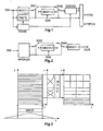
- Fig. 1 the magnitude values of each successive overlapping block or segment or section of samples of a coder input audio signal CIS are weighted by a window function and transformed in a long (i.e. a high frequency resolution) MDCT filter bank or transform stage or step MDCT-1, providing corresponding transform coefficients or frequency bins.
- a second MDCT filter bank or transform stage or step MDCT-2 is applied to the frequency bins of the first forward transform (i.e. on the same block) in order to change the frequency and temporal filter resolutions, i.e.
- a series of non-uniform MDCTs is applied to the frequency data, whereby a non-uniform time/frequency representation is generated.
- the amplitude values of each successive overlapping section of frequency bins of the first forward transform are weighted by a window function prior to the second-stage transform.
- the window functions used for the weighting are explained in connection with figures 4 to 7 and equations (3) and (4).
- the sections are 50% overlapping.
- the degree of overlapping can be different.
- that step or stage when considered alone is similar to the above-mentioned Edler codec.
- the switching on or off of the second MDCT filter bank MDCT-2 can be performed using first and second switches SW1 and SW2 and is controlled by a filter bank control unit or step FBCTL that is integrated into, or is operating in parallel to, a psycho-acoustic analyser stage or step PSYM, which both receive signal CIS.
- Stage or step PSYM uses temporal and spectral information from the input signal CIS.
- the topology or status of the 2nd stage filter MDCT-2 is coded as side information into the coder output bit stream COS.
- the frequency data output from switch SW2 is quantised and entropy encoded in a quantiser and entropy encoding stage or step QUCOD that is controlled by psycho-acoustic analyser PSYM, in particular the quantisation step sizes.
- stages QUCOD encoded frequency bins
- FBCTL topology or status information or temporal resolution control information or switching information SWI or side information
- the quantising can be replaced by inserting a distortion signal.
- the decoder input bit stream DIS is de-packed and correspondingly decoded and inversely 'quantised' (or re-quantised) in a depacking, decoding and re-quantising stage or step DPCRQU, which provides correspondingly decoded frequency bins and switching information SWI.
- a correspondingly inverse non-uniform MDCT step or stage iMDCT-2 is applied to these decoded frequency bins using e.g. switches SW3 and SW4, if so signalled by the bit stream via switching information SWI.
- the amplitude values of each successive section of inversely transformed values are weighted by a window function following the transform in step or stage iMDCT-2, which weighting is followed by an overlap-add processing.
- the signal is reconstructed by applying either to the decoded frequency bins or to the output of step or stage iMDCT-2 a correspondingly inverse high-resolution MDCT step or stage iMDCT-1.
- the amplitude values of each successive section of inversely transformed values are weighted by a window function following the transform in step or stage iMDCT-1, which weighting is followed by an overlap-add processing. Thereafter, the PCM audio decoder output signal DOS.
- the transform lengths applied at decoding side mirror the corresponding transport lengths applied at encoding side, i.e. the same block of received values is inverse transformed twice.
- the window functions used for the weighting are explained in connection with figures 4 to 7 and equations (3) and (4).
- the sections are 50% overlapping.
- the degree of overlapping can be different.
- Fig. 3 depicts the above-mentioned processing, i.e. applying first and second stage filter banks.
- On the left side a block of time domain samples is windowed and transformed in a long MDCT to the frequency domain.
- a series of non-uniform MDCTs is applied to the frequency data to generate a non-uniform time/frequency representation shown at the right side of Fig. 3 .
- the time/frequency representations are displayed in grey or hatched.
- the time/frequency representation (on the left side) of the first stage transform or filter bank MDCT-1 offers a high frequency or spectral resolution that is optimum for encoding stationary signal sections.
- Filter banks MDCT-1 and iMDCT-1 represent a constant-size MDCT and iMDCT pair with 50% overlapping blocks.
- Overlay-and-add (OLA) is used in filter bank iMDCT-1 to cancel the time domain alias. Therefore the filter bank pair MDCT-1 and iMDCT-1 is capable of theoretical perfect reconstruction.
- Fast changing signal sections, especially transient signals, are better represented in time/frequency with resolutions matching the human perception or representing a maximum signal compaction tuned to time/frequency.
- This is achieved by applying the second transform filter bank MDCT-2 onto a block of selected frequency bins of the first forward transform filter bank MDCT-1.
- the second forward transform is characterised by using 50% overlapping windows of different sizes, using transition window functions (i.e.
- 'Edler window functions' each of which having asymmetric slopes) when switching from one size to another, as shown in the medium section of Fig. 3 .
- Window sizes start from length 4 to length 2 n , wherein n is an integer number greater 2.
- a window size of '4' combines two frequency bins and doubled time resolution, a window size of 2 n combines 2 (n-1) frequency bins and increases the temporal resolution by factor 2 (n-1) .
- Special start and stop window functions are used at the beginning and at the end of the series of MDCTs.
- filter bank iMDCT-2 applies the inverse transform including OLA. Thereby the filter bank pair MDCT-2/iMDCT-2 is capable of theoretical perfect reconstruction.
- the output data of filter bank MDCT-2 is combined with single-resolution bins of filter bank MDCT-1 which were not included when applying filter bank MDCT-2.
- the output of each transform or MDCT of filter bank MDCT-2 can be interpreted as time-reversed temporal samples of the combined frequency bins of the first forward transform.
- a construction of a non-uniform time/frequency representation as depicted at the right side of Fig. 3 now becomes feasible.
- the filter bank control unit or step FBCTL performs a signal analysis of the actual processing block using time data and excitation patterns from the psycho-acoustic model in psycho-acoustic analyser stage or step PSYM.
- it switches during transient signal sections to fixed-filter topologies of filter bank MDCT-2, which filter bank may make use of a time/frequency resolution of human perception.
- filter bank MDCT-2 which filter bank may make use of a time/frequency resolution of human perception.
- only few bits of side information are required for signalling to the decoding side, as a code-book entry, the desired topology of filter bank iMDCT-2.
- the filter bank control unit or step FBCTL evaluates the spectral and temporal flatness of input signal CIS and determines a flexible filter topology of filter bank MDCT-2. In this embodiment it is sufficient to transmit to the decoder the coded starting locations of the start window, transition window and stop window positions in order to enable the construction of filter bank iMDCT-2.
- the psycho-acoustic model makes use of the high spectral resolution equivalent to the resolution of filter bank MDCT-1 and, at the same time, of a coarse spectral but high temporal resolution signal analysis. This second resolution can match the coarsest frequency resolution of filter bank MDCT-2.
- the psycho-acoustic model can also be driven directly by the output of filter bank MDCT-1, and during transient signal sections by the time/frequency representation as depicted at the right side of Fig. 3 following applying filter bank MDCT-2.
- filter bank MDCT-1 the output of filter bank MDCT-1
- transient signal sections by the time/frequency representation as depicted at the right side of Fig. 3 following applying filter bank MDCT-2.
- the Modified Discrete Cosine Transformation (MDCT) and the inverse MDCT (iMDCT) can be considered as representing a critically sampled filter bank.
- the MDCT was first named " Oddly-stacked time domain alias cancellation transform" by J.P. Princen and A.B. Bradley in "Analysis/synthesis filter bank design based on time domain aliasing cancellation", IEEE Transactions on Acoust. Speech Sig. Proc. ASSP-34 (5), pp.1153-1161, 1986 . H.S. Malvar, "Signal processing with lapped transform", Artech House Inc., Norwood, 1992 , and M. Temerinac, B.
- the inverse transform converts in each case M frequency bins to N time samples and thereafter the magnitude values are weighted by window function h(n), wherein N and M are integer numbers.
- a following overlay-add procedure cancels out the time alias.
- Edler has shown switching the MDCT time-frequency resolution using transition windows.
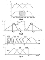
- An example of switching (caused by transient conditions) using transition windows 1, 10 from a long transform to eight short transforms is depicted in the bottom part of Fig. 4 , which shows the gain G of the window functions in vertical direction and the time, i.e. the input signal samples, in horizontal direction.
- Fig. 4 shows the gain G of the window functions in vertical direction and the time, i.e. the input signal samples, in horizontal direction.
- three successive basic window functions A, B and C as applied in steady state conditions are shown.
- the first-stage filter bank MDCT-1, iMDCT-1 is a high resolution MDCT filter bank having a sub-band filter bandwidth of e.g. 15-25 Hz. For audio sampling rates of e.g. 32-48 kHz a typical length of N L is 2048 samples.
- the window function h(n) satisfies equations (3) and (4).
- Following application of filter MDCT-1 there are 1024 frequency bins in the preferred embodiment. For stationary input signal sections, these bins are quantised according to psycho-acoustic considerations.
- Fast changing, transient input signal sections are processed by the additional MDCT applied to the bins of the first MDCT. This additional step or stage merges two, four, eight, sixteen or more sub-bands and thereby increases the temporal resolution, as depicted in the right part of Fig. 3 .
- Fig. 6 shows an example sequence of applied windowing for the second-stage MDCTs within the frequency domain. Therefore the horizontal axis is related to f/bins.
- the transition window functions are designed according to Fig. 5 and equation (6), like in the time domain.
- Special start window functions STW and stop window functions SPW handle the start and end sections of the transformed signal, i.e. the first and the last MDCT.
- the design principle of these start and stop window functions is shown in Fig. 7 .
- One half of these window functions mirrors a half-window function of a normal or regular window function NW, e.g. a sine window function according to equation (5).
- NW normal or regular window function
- the adjacent half has a continuous gain of 'one' (or a 'unity' constant) and the other half has the gain zero.
- each one of such new MDCT can be regarded as a new frequency line (bin) that has combined the original windowed bins, and the time reversed output of that new MDCT can be regarded as the new temporal blocks.
- the presentation in Figures 8 and 9 is based on this assumption or condition.
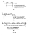
- Indices ki in Fig. 6 indicate the regions of changing temporal resolution. Frequency bins starting from position zero up to position k1 -1 are copied from (i.e. represent) the first forward transform (MDCT-1), which corresponds to a single temporal resolution. Bins from index k1- 1 to index k2 are transformed to g1 frequency lines. g1 is equal to the number of transforms performed (that number corresponds to the number of overlapping windows and can be considered as the number of frequency bins in the second or upper transform level MDCT-2). The start index is bin k1 -1 because index k1 is selected as the second sample in the first forward transform in Fig. 6 (the first sample has a zero amplitude, see also Fig. 10a ).
- the regular window size is e.g. 8 bins, which size results in a section with quadrupled temporal resolution.
- the next section in Fig. 6 is transformed by windows (transform length) spanning e.g. 16 bins, which size results in sections having eightfold temporal resolution.
- Windowing starts at bin k3 -5. If this is the last resolution selected (as is true for Fig. 6 ), then it ends at bin k4 +4, otherwise at bin k4 .
- the order (i.e. the length) of the second-stage transform is variable over successive transform blocks, starting from frequency bins corresponding to low frequency lines, the first second-stage MDCTs will start with a small order and the following second-stage MDCTs will have a higher order. Transition windows fulfilling the characteristics for perfect reconstruction are used.
- Fig. 10 shows a sample-accurate assignment of frequency indices that mark areas of a second (i.e. cascaded) transform (MDCT-2), which second transform achieves a better temporal resolution.
- the circles represent bin positions, i.e. frequency lines of the first or initial transform (MDCT-1).
- Fig. 10a shows the area of 4-point second-stage MDCTs that are used to provide doubled temporal resolution.
- the five MDCT sections depicted create five new spectral lines.
- Fig. 10b shows the area of 8-point second-stage MDCTs that are used to provide fourfold temporal resolution.
- Three MDCT sections are depicted.
- Fig. 10c shows the area of 16-point second-stage MDCTs that are used to provide eightfold temporal resolution. Four MDCT sections are depicted.
- filter bank iMDCT-1 the iMDCT of the long transform blocks including the overlay-add procedure (OLA) to cancel the time alias.
- OLA overlay-add procedure
- the simplest embodiment makes use of a single fixed topology for filter bank MDCT-2/iMDCT-2 and signals this with a single bit in the transferred bitstream.
- a corresponding number of bits is used for signalling the currently used one of the topologies.
- More advanced embodiments pick the best out of a set of fixed code-book topologies and signal a corresponding code-book entry inside the bitstream.
- a corresponding side information is transmitted in the encoding output bitstream.
- indices k1, k2 , k3 , k4, ..., kend are transmitted.
- k2 is transmitted with the same value as in k1 equal to bin zero.
- the value transmitted in kend is copied to k4 , k3, ... .
- bi is a place holder for a frequency bin as a value.
- Topology with 1x, 2x, 4x, 8x temporal resolutions (like in Fig. 6 ) b1>1 b2 b3 b4 b4
- FIG. 8 and 9 depict two examples of multi-resolution T/F (time/frequency) energy plots of a second-stage filter bank.
- Fig. 8 shows an '8x temporal resolution only' topology.
- a time domain signal transient in Fig. 8a is depicted as amplitude over time (time expressed in samples).
- Fig. 8b shows the corresponding T/F energy plot of the first-stage MDCT (frequency in bins over normalised time corresponding to one transform block), and
- Fig. 8c shows the corresponding T/F plot of the second-stage MDCTs (8*128 time-frequency tiles).
- Fig. 9 shows a '1x 2x, 4x, 8x topology'.
- FIG. 9a is depicted as amplitude over time (time expressed in samples).
- the simplest embodiment can use any state-of-the-art transient detector to switch to a fixed topology matching, or for coming close to, the T/F resolution of human perception.
- the preferred embodiment uses a more advanced control processing:
- the topology is determined by the following steps:
- the MDCT can be replaced by a DCT, in particular a DCT-4.
- a DCT in particular a DCT-4.
- the psycho-acoustic analyser PSYM is replaced by an analyser taking into account the human visual system properties.
- the invention can be use in a watermark embedder.
- the cascaded filter bank is used with a audio watermarking system.
- a first (integer) MDCT is performed in the watermarking encoder.
- a first watermark is inserted into bins 0 to k1-1 using a psycho-acoustic controlled embedding process.
- the purpose of this watermark can be frame synchronisation at the watermark decoder.
- Second-stage variable size (integer) MDCTs are applied to bins starting from bin index k1 as described before.
- the output of this second stage is resorted to gain a time-frequency expression by interpreting the output as time-reversed temporal blocks and each second-stage MDCT as a new frequency line (bin).
- a second watermark signal is added onto each one of these new frequency lines by using an attenuation factor that is controlled by psycho-acoustic considerations.
- the data is resorted and the inverse (integer) MDCT (related to the above-mentioned second-stage MDCT) is performed as described for the above embodiments (decoder), including windowing and overlay/add.
- the full spectrum related to the first forward transform is restored.
- the full-size inverse (integer) MDCT performed onto that data, windowing and overlay/add restores a time signal with a watermark embedded.
- the multi-resolution filter bank is also used within the watermark decoder.
- the topology of the second-stage MDCTs is fixed by the application.
Landscapes
- Engineering & Computer Science (AREA)
- Physics & Mathematics (AREA)
- Spectroscopy & Molecular Physics (AREA)
- Computational Linguistics (AREA)
- Signal Processing (AREA)
- Health & Medical Sciences (AREA)
- Audiology, Speech & Language Pathology (AREA)
- Human Computer Interaction (AREA)
- Acoustics & Sound (AREA)
- Multimedia (AREA)
- Compression, Expansion, Code Conversion, And Decoders (AREA)
Description
- The invention relates to a method and to an apparatus for encoding and decoding an audio signal using transform coding and adaptive switching of the temporal resolution in the spectral domain.
- Perceptual audio codecs make use of filter banks and MDCT (modified discrete cosine transform, a forward transform) in order to achieve a compact representation of the audio signal, i.e. a redundancy reduction, and to be able to reduce irrelevancy from the original audio signal. During quasi-stationary parts of the audio signal a high frequency or spectral resolution of the filter bank is advantageous in order to achieve a high coding gain, but this high frequency resolution is coupled to a coarse temporal resolution that becomes a problem during transient signal parts. A well-know consequence are audible pre-echo effects.
- B. Edler, "Codierung von Audiosignalen mit überlappender Transformation und adaptiven Fensterfunktionen", Frequenz, Vol.43, No.9, p.252-256, September 1989, discloses adaptive window switching in the time domain and/or transform length switching, which is a switching between two resolutions by alternatively using two window functions with different length.
US-A-6029126 describes a long transform, whereby the temporal resolution is increased by combining spectral bands using a matrix multiplication. Switching between different fixed resolutions is carried out in order to avoid window switching in the time domain. This can be used to create non-uniform filter-banks having two different resolutions.WO-A-03/019332 -
US-2007/0016405 discloses a "time-split transform" in the frequency domain to improve the temporal resolution for transient signal regions. Optionally the time-split transform may be followed by a reduction of the window size in the time domain if the achieved results do not produce sufficient quality. - The above-mentioned window and/or transform length switching disclosed by Edler is sub-optimum because of long delay due to long look-ahead and low frequency resolution of short blocks, which prevents providing a sufficient resolution for optimum irrelevancy reduction.
- A problem to be solved by the invention is to provide an improved coding/decoding gain by applying a high frequency resolution as well as high temporal resolution for transient audio signal parts. This problem is solved by the methods disclosed in
claims claims - The invention achieves improved coding/decoding quality by applying on top of the output of a first filter bank a second non-uniform filter bank, i.e. a cascaded MDCT. The inventive codec uses switching to an additional extension filter bank (or multi-resolution filter bank) in order to regroup the time-frequency representation during transient or fast changing audio signal sections.
By applying a corresponding switching control, pre-echo effects are avoided and a high coding gain is achieved. Advantageously, the inventive codec has a low coding delay (no look-ahead). - In principle, the inventive encoding method is suited for encoding an input signal, e.g. an audio signal, using a first forward transform into the frequency domain being applied to first-length sections of said input signal, and using adaptive switching of the temporal resolution, followed by quantisation and entropy encoding of the values of the resulting frequency domain bins, wherein control of said switching, quantisation and/or entropy encoding is derived from a psycho-acoustic analysis of said input signal, including the steps of:
- adaptively controlling said temporal resolution is achieved by performing a second forward transform following said first forward transform and being applied to second-length sections of said transformed first-length sections, wherein said second length is smaller than said first length and either the output values of said first forward transform or the output values of said second forward transform are processed in said quantisation and entropy encoding;
- attaching to the encoding output signal corresponding temporal resolution control information as side information.
- In principle the inventive encoding apparatus is suited for encoding an input signal, e.g. an audio signal, said apparatus including:
- first forward transform means being adapted for transforming first-length sections of said input signal into the frequency domain;
- second forward transform means being adapted for transforming second-length sections of said transformed first-length sections, wherein said second length is smaller than said first length;
- means being adapted for quantising and entropy encoding the output values of said first forward transform means or the output values of said second forward transform means;
- means being adapted for controlling said quantisation and/or entropy encoding and for controlling adaptively whether said output values of said first forward transform means or the output values of said second forward transform means are processed in said quantising and entropy encoding means, wherein said controlling is derived from a psycho-acoustic analysis of said input signal;
- means being adapted for attaching to the encoding apparatus output signal corresponding temporal resolution control information as side information.
- In principle, the inventive decoding method is suited for decoding an encoded signal, e.g. an audio signal, that was encoded using a first forward transform into the frequency domain being applied to first-length sections of said input signal, wherein the temporal resolution was adaptively switched by performing a second forward transform following said first forward transform and being applied to second-length sections of said transformed first-length sections, wherein said second length is smaller than said first length and either the output values of said first forward transform or the output values of said second forward transform were processed in a quantisation and entropy encoding, and wherein control of said switching, quantisation and/or entropy encoding was derived from a psycho-acoustic analysis of said input signal and corresponding temporal resolution control information was attached to the encoding output signal as side information, said decoding method including the steps of:
- providing from said encoded signal said side information;
- inversely quantising and entropy decoding said encoded signal;
- corresponding to said side information, either performing a first forward inverse transform into the time domain, said first forward inverse transform operating on first-length signal sections of said inversely quantised and entropy decoded signal and said first forward inverse transform providing the decoded signal,
- In principle, the inventive decoding apparatus is suited for decoding an encoded signal, e.g. an audio signal, that was encoded using a first forward transform into the frequency domain being applied to first-length sections of said input signal, wherein the temporal resolution was adaptively switched by performing a second forward transform following said first forward transform and being applied to second-length sections of said transformed first-length sections, wherein said second length is smaller than said first length and either the output values of said first forward transform or the output values of said second forward transform were processed in a quantisation and entropy encoding, and wherein control of said switching, quantisation and/or entropy encoding was derived from a psycho-acoustic analysis of said input signal and corresponding temporal resolution control information was attached to the encoding output signal as side information, said apparatus including:
- means being adapted for providing from said side information and for inversely quantising and entropy decoding said encoded signal;
- means being adapted for, corresponding to said side information, either performing a first forward inverse transform into the time domain, said first forward inverse transform operating on first-length signal sections of said inversely quantised and entropy decoded signal and said first forward inverse transform providing the decoded signal,
- Advantageous additional embodiments of the invention are disclosed in the respective dependent claims.
- Exemplary embodiments of the invention are described with reference to the accompanying drawings, which show in:
- Fig. 1
- inventive encoder;
- Fig. 2
- inventive decoder;
- Fig. 3
- a block of audio samples that is windowed and trans-formed with a long MDCT, and series of non-uniform MDCTs applied to the frequency data;
- Fig. 4
- changing the time-frequency resolution by changing the block length of the MDCT;
- Fig. 5
- transition windows;
- Fig. 6
- window sequence example for second-stage MDCTs;
- Fig. 7
- start and stop windows for first and last MDCT;
- Fig. 8
- time domain signal of a transient, T/F plot of first MDCT stage and T/F plot of second-stage MDCTs with an 8-fold temporal resolution topology;
- Fig. 9
- time domain signal of a transient, second-stage filter bank T/F plot of a single, 2-fold, 4-fold and 8-fold temporal resolution topology;
- Fig. 10
- more detail for the window processing according to
Fig. 6 . - In
Fig. 1 , the magnitude values of each successive overlapping block or segment or section of samples of a coder input audio signal CIS are weighted by a window function and transformed in a long (i.e. a high frequency resolution) MDCT filter bank or transform stage or step MDCT-1, providing corresponding transform coefficients or frequency bins. During transient audio signal sections a second MDCT filter bank or transform stage or step MDCT-2, either with shorter fixed transform length or preferably a multi-resolution MDCT filter bank having different shorter transform lengths, is applied to the frequency bins of the first forward transform (i.e. on the same block) in order to change the frequency and temporal filter resolutions, i.e. a series of non-uniform MDCTs is applied to the frequency data, whereby a non-uniform time/frequency representation is generated. The amplitude values of each successive overlapping section of frequency bins of the first forward transform are weighted by a window function prior to the second-stage transform. The window functions used for the weighting are explained in connection withfigures 4 to 7 and equations (3) and (4). In case of MDCT or integer MDCT transforms, the sections are 50% overlapping. In case a different transform is used the degree of overlapping can be different.
In case only two different transform lengths are used for stage or step MDCT-2, that step or stage when considered alone is similar to the above-mentioned Edler codec.
The switching on or off of the second MDCT filter bank MDCT-2 can be performed using first and second switches SW1 and SW2 and is controlled by a filter bank control unit or step FBCTL that is integrated into, or is operating in parallel to, a psycho-acoustic analyser stage or step PSYM, which both receive signal CIS. Stage or step PSYM uses temporal and spectral information from the input signal CIS. The topology or status of the 2nd stage filter MDCT-2 is coded as side information into the coder output bit stream COS. The frequency data output from switch SW2 is quantised and entropy encoded in a quantiser and entropy encoding stage or step QUCOD that is controlled by psycho-acoustic analyser PSYM, in particular the quantisation step sizes. The output from stages QUCOD (encoded frequency bins) and FBCTL (topology or status information or temporal resolution control information or switching information SWI or side information) is combined in a stream packer step or stage STRPCK and forms the output bit stream COS.
The quantising can be replaced by inserting a distortion signal. - In
Fig. 2 , at decoder side, the decoder input bit stream DIS is de-packed and correspondingly decoded and inversely 'quantised' (or re-quantised) in a depacking, decoding and re-quantising stage or step DPCRQU, which provides correspondingly decoded frequency bins and switching information SWI. A correspondingly inverse non-uniform MDCT step or stage iMDCT-2 is applied to these decoded frequency bins using e.g. switches SW3 and SW4, if so signalled by the bit stream via switching information SWI. The amplitude values of each successive section of inversely transformed values are weighted by a window function following the transform in step or stage iMDCT-2, which weighting is followed by an overlap-add processing. The signal is reconstructed by applying either to the decoded frequency bins or to the output of step or stage iMDCT-2 a correspondingly inverse high-resolution MDCT step or stage iMDCT-1. The amplitude values of each successive section of inversely transformed values are weighted by a window function following the transform in step or stage iMDCT-1, which weighting is followed by an overlap-add processing. Thereafter, the PCM audio decoder output signal DOS. The transform lengths applied at decoding side mirror the corresponding transport lengths applied at encoding side, i.e. the same block of received values is inverse transformed twice.
The window functions used for the weighting are explained in connection withfigures 4 to 7 and equations (3) and (4). In case of inverse MDCT or inverse integer MDCT transforms, the sections are 50% overlapping. In case a different inverse transform is used the degree of overlapping can be different. -
Fig. 3 depicts the above-mentioned processing, i.e. applying first and second stage filter banks. On the left side a block of time domain samples is windowed and transformed in a long MDCT to the frequency domain. During transient audio signal sections a series of non-uniform MDCTs is applied to the frequency data to generate a non-uniform time/frequency representation shown at the right side ofFig. 3 . The time/frequency representations are displayed in grey or hatched.
The time/frequency representation (on the left side) of the first stage transform or filter bank MDCT-1 offers a high frequency or spectral resolution that is optimum for encoding stationary signal sections. Filter banks MDCT-1 and iMDCT-1 represent a constant-size MDCT and iMDCT pair with 50% overlapping blocks. Overlay-and-add (OLA) is used in filter bank iMDCT-1 to cancel the time domain alias. Therefore the filter bank pair MDCT-1 and iMDCT-1 is capable of theoretical perfect reconstruction.
Fast changing signal sections, especially transient signals, are better represented in time/frequency with resolutions matching the human perception or representing a maximum signal compaction tuned to time/frequency. This is achieved by applying the second transform filter bank MDCT-2 onto a block of selected frequency bins of the first forward transform filter bank MDCT-1.
The second forward transform is characterised by using 50% overlapping windows of different sizes, using transition window functions (i.e. 'Edler window functions' each of which having asymmetric slopes) when switching from one size to another, as shown in the medium section ofFig. 3 . Window sizes start fromlength 4 tolength 2n, wherein n is an integer number greater 2. A window size of '4' combines two frequency bins and doubled time resolution, a window size of 2ncombines 2(n-1) frequency bins and increases the temporal resolution byfactor 2(n-1). Special start and stop window functions (transition windows) are used at the beginning and at the end of the series of MDCTs. At decoding side, filter bank iMDCT-2 applies the inverse transform including OLA. Thereby the filter bank pair MDCT-2/iMDCT-2 is capable of theoretical perfect reconstruction.
The output data of filter bank MDCT-2 is combined with single-resolution bins of filter bank MDCT-1 which were not included when applying filter bank MDCT-2.
The output of each transform or MDCT of filter bank MDCT-2 can be interpreted as time-reversed temporal samples of the combined frequency bins of the first forward transform. Advantageously, a construction of a non-uniform time/frequency representation as depicted at the right side ofFig. 3 now becomes feasible. - The filter bank control unit or step FBCTL performs a signal analysis of the actual processing block using time data and excitation patterns from the psycho-acoustic model in psycho-acoustic analyser stage or step PSYM. In a simplified embodiment it switches during transient signal sections to fixed-filter topologies of filter bank MDCT-2, which filter bank may make use of a time/frequency resolution of human perception. Advantageously, only few bits of side information are required for signalling to the decoding side, as a code-book entry, the desired topology of filter bank iMDCT-2.
- In a more complex embodiment, the filter bank control unit or step FBCTL evaluates the spectral and temporal flatness of input signal CIS and determines a flexible filter topology of filter bank MDCT-2. In this embodiment it is sufficient to transmit to the decoder the coded starting locations of the start window, transition window and stop window positions in order to enable the construction of filter bank iMDCT-2.
- The psycho-acoustic model makes use of the high spectral resolution equivalent to the resolution of filter bank MDCT-1 and, at the same time, of a coarse spectral but high temporal resolution signal analysis. This second resolution can match the coarsest frequency resolution of filter bank MDCT-2.
- As an alternative, the psycho-acoustic model can also be driven directly by the output of filter bank MDCT-1, and during transient signal sections by the time/frequency representation as depicted at the right side of
Fig. 3 following applying filter bank MDCT-2.
In the following, a more detailed system description is provided. - The Modified Discrete Cosine Transformation (MDCT) and the inverse MDCT (iMDCT) can be considered as representing a critically sampled filter bank. The MDCT was first named "Oddly-stacked time domain alias cancellation transform" by J.P. Princen and A.B. Bradley in "Analysis/synthesis filter bank design based on time domain aliasing cancellation", IEEE Transactions on Acoust. Speech Sig. Proc. ASSP-34 (5), pp.1153-1161, 1986.
H.S. Malvar, "Signal processing with lapped transform", Artech House Inc., Norwood, 1992, and M. Temerinac, B. Edler, "A unified approach to lapped orthogonal transforms", IEEE Transactions on Image Processing, Vol.1, No.1, pp.111-116, January 1992, have called it "Modulated Lapped Transform (MLT)" and have shown its relations to lapped orthogonal transforms in general and have also proved it to be a special case of a QMF filter bank.
The equations of the transform and the inverse transform are given in equations (1) and (2):

In these transforms, 50% overlaying blocks are processed. At encoding side, in each case, a block of N samples is windowed and the magnitude values are weighted by window function h(n) and is thereafter transformed to K=N/2 frequency bins, wherein N is an integer number. At decoding side, the inverse transform converts in each case M frequency bins to N time samples and thereafter the magnitude values are weighted by window function h(n), wherein N and M are integer numbers. A following overlay-add procedure cancels out the time alias. The window function h(n) must fulfil some constraints to enable perfect reconstruction, see equations (3) and (4) :

- Analysis and synthesis window functions can also be different but the inverse transform lengths used in the decoding correspond to the transform lengths used in the encoding. However, this option is not considered here. A suitable window function is the sine window function given in (5):

- In the above-mentioned article, Edler has shown switching the MDCT time-frequency resolution using transition windows. An example of switching (caused by transient conditions) using
transition windows Fig. 4 , which shows the gain G of the window functions in vertical direction and the time, i.e. the input signal samples, in horizontal direction. In the upper part of this figure three successive basic window functions A, B and C as applied in steady state conditions are shown. - The transition window functions have the length NL of the long transform. At the smaller-window side end there are r zero-amplitude window function samples. Towards the window function centre located at NL/2, a mirrored half-window function for the small transform (having a length of Nshort samples) is following, further followed by r window function samples having a value of 'one' (or a 'unity' constant). The principle is depicted for a transition to short window at the left side of
Fig. 5 and for a transition from short window at the right side ofFig. 5 . Value r is given by
- The first-stage filter bank MDCT-1, iMDCT-1 is a high resolution MDCT filter bank having a sub-band filter bandwidth of e.g. 15-25 Hz. For audio sampling rates of e.g. 32-48 kHz a typical length of NL is 2048 samples. The window function h(n) satisfies equations (3) and (4). Following application of filter MDCT-1 there are 1024 frequency bins in the preferred embodiment. For stationary input signal sections, these bins are quantised according to psycho-acoustic considerations.
Fast changing, transient input signal sections are processed by the additional MDCT applied to the bins of the first MDCT. This additional step or stage merges two, four, eight, sixteen or more sub-bands and thereby increases the temporal resolution, as depicted in the right part ofFig. 3 . -
Fig. 6 shows an example sequence of applied windowing for the second-stage MDCTs within the frequency domain. Therefore the horizontal axis is related to f/bins. The transition window functions are designed according toFig. 5 and equation (6), like in the time domain. Special start window functions STW and stop window functions SPW handle the start and end sections of the transformed signal, i.e. the first and the last MDCT. The design principle of these start and stop window functions is shown inFig. 7 . One half of these window functions mirrors a half-window function of a normal or regular window function NW, e.g. a sine window function according to equation (5). Of other half of these window functions, the adjacent half has a continuous gain of 'one' (or a 'unity' constant) and the other half has the gain zero. - Due to the properties of MDCT, performing MDCT-2 can also be regarded as a partial inverse transformation. When applying the forward MDCTs of the second stage MDCTs, each one of such new MDCT (MDCT-2) can be regarded as a new frequency line (bin) that has combined the original windowed bins, and the time reversed output of that new MDCT can be regarded as the new temporal blocks. The presentation in
Figures 8 and 9 is based on this assumption or condition. - Indices ki in
Fig. 6 indicate the regions of changing temporal resolution. Frequency bins starting from position zero up to position k1-1 are copied from (i.e. represent) the first forward transform (MDCT-1), which corresponds to a single temporal resolution.
Bins from index k1-1 to index k2 are transformed to g1 frequency lines. g1 is equal to the number of transforms performed (that number corresponds to the number of overlapping windows and can be considered as the number of frequency bins in the second or upper transform level MDCT-2). The start index is bin k1-1 because index k1 is selected as the second sample in the first forward transform inFig. 6 (the first sample has a zero amplitude, see alsoFig. 10a ).
g1 = (number_of_windowed_bins)/(N/2) -1 = (k2 - k1 +1)/2 -1, with a regular window size N of e.g. 4 bins, which size creates a section with doubled temporal resolution.
Bins from index k2-3 to index k3+4 are combined to g2 frequency lines (transforms), i.e. g2 = (k3 - k2 +2)/4 -1. The regular window size is e.g. 8 bins, which size results in a section with quadrupled temporal resolution.
The next section inFig. 6 is transformed by windows (transform length) spanning e.g. 16 bins, which size results in sections having eightfold temporal resolution. Windowing starts at bin k3-5. If this is the last resolution selected (as is true forFig. 6 ), then it ends atbin k4+ 4, otherwise at bin k4.
Where the order (i.e. the length) of the second-stage transform is variable over successive transform blocks, starting from frequency bins corresponding to low frequency lines, the first second-stage MDCTs will start with a small order and the following second-stage MDCTs will have a higher order. Transition windows fulfilling the characteristics for perfect reconstruction are used. - The processing according to
Fig. 6 is further explained inFig. 10 , which shows a sample-accurate assignment of frequency indices that mark areas of a second (i.e. cascaded) transform (MDCT-2), which second transform achieves a better temporal resolution. The circles represent bin positions, i.e. frequency lines of the first or initial transform (MDCT-1).
Fig. 10a shows the area of 4-point second-stage MDCTs that are used to provide doubled temporal resolution. The five MDCT sections depicted create five new spectral lines.Fig. 10b shows the area of 8-point second-stage MDCTs that are used to provide fourfold temporal resolution. Three MDCT sections are depicted.Fig. 10c shows the area of 16-point second-stage MDCTs that are used to provide eightfold temporal resolution. Four MDCT sections are depicted. - At decoder side, stationary signals are restored using filter bank iMDCT-1, the iMDCT of the long transform blocks including the overlay-add procedure (OLA) to cancel the time alias.
When so signalled in the bitstream, the decoding or the decoder, respectively, switches to the multi-resolution filter bank iMDCT-2 by applying a sequence of iMDCTs according to the signalled topology (including OLA) before applying filter bank iMDC7-1. - The simplest embodiment makes use of a single fixed topology for filter bank MDCT-2/iMDCT-2 and signals this with a single bit in the transferred bitstream. In case more fixed sets of topologies are used, a corresponding number of bits is used for signalling the currently used one of the topologies. More advanced embodiments pick the best out of a set of fixed code-book topologies and signal a corresponding code-book entry inside the bitstream.
- In embodiments were the filter topology of the second-stage transforms is not fixed, a corresponding side information is transmitted in the encoding output bitstream. Preferably, indices k1, k2, k3, k4, ..., kend are transmitted.
Starting with quadrupled resolution, k2 is transmitted with the same value as in k1 equal to bin zero. In topologies ending with temporal resolutions coarser than the maximum temporal resolution, the value transmitted in kend is copied to k4, k3, ... . - The following table illustrates this with some examples. bi is a place holder for a frequency bin as a value.
Indices signalling topology Topology k1 k2 k3 k4 kend Topology with 1x, 2x, 4x, 8x , 16x temporal resolutions b1>1 b2 b3 b4 b5 Topology with 1x, 2x, 4x, 8x temporal resolutions (like in Fig. 6 )b1>1 b2 b3 b4 b4 Topology with 8x temporal resolution only 0 0 0 bmax bmax Topology with 4x, 8x and 16x temporal resolution 0 0 b2 b3 bmax - Due to temporal psycho-acoustic properties of the human auditory system it is sufficient to restrict this to topologies with temporal resolution increasing with frequency.
-
Figures 8 and 9 depict two examples of multi-resolution T/F (time/frequency) energy plots of a second-stage filter bank.
Fig. 8 shows an '8x temporal resolution only' topology. A time domain signal transient inFig. 8a is depicted as amplitude over time (time expressed in samples).Fig. 8b shows the corresponding T/F energy plot of the first-stage MDCT (frequency in bins over normalised time corresponding to one transform block), andFig. 8c shows the corresponding T/F plot of the second-stage MDCTs (8*128 time-frequency tiles).
Fig. 9 shows a '1x Fig. 9a is depicted as amplitude over time (time expressed in samples).Fig. 9b shows the corresponding T/F plot of the second-stage MDCTs, whereby the frequency resolution for the lower band part is selected proportional to the bandwidths of perception of the human auditory system (critical bands), with bN1 = 16, bN2 = 16, bN4 = 16, bN8 = 114, for 1024 coefficients in total (these numbers have the following meaning: 16 frequency lines having single temporal resolution, 16 frequency lines having double, 16 frequency lines having 4 times, and 114 frequency lines having 8 times temporal resolution). For the low frequencies there is a single partition, followed by two and four partitions and, above about f=50, eight partitions. - The simplest embodiment can use any state-of-the-art transient detector to switch to a fixed topology matching, or for coming close to, the T/F resolution of human perception. The preferred embodiment uses a more advanced control processing:
- Calculate a spectral flatness measure SFM, e.g. according to equation (7), over selected bands of M frequency lines (fbin) of the power spectral density Pm by using a discrete Fourier transform (DFT) of a windowed signal of a long transform block with NL samples, i.e. the length of MDCT-1 (the selected bands are proportional to critical bands);
- Divide the analysis block of NL samples into S≥8 overlapping blocks and apply S windowed DFTs on the sub-blocks. Arrange the result as a matrix having S columns (temporal resolution, tblock) and a number of rows according the number of frequency lines of each DFT, S being an integer;
- Calculate S spectrograms Ps, e.g. general power spectral densities or psycho-acoustically shaped spectrograms (or excitation patterns);
- For each frequency line determine a temporal flatness measure (TFM) according to equation (8);
- Use the SFM vector to determine tonal or noisy bands, and use the TFM vector to recognise the temporal variations within this bands. Use threshold values to decide whether or not to switch to the multi-resolution filter bank and what topology to pick.


- In a different embodiment, the topology is determined by the following steps:
- performing a spectral flatness measure SFM using said first forward transform, by determining for selected frequency bands the spectral power of transform bins and dividing the arithmetic mean value of said spectral power values by their geometric mean value;
- sub-segmenting an un-weighted input signal section, performing weighting and short transforms on m sub-sections where the frequency resolution of these transforms corresponds to said selected frequency bands;
- for each frequency line consisting of m transform segments, determining the spectral power and calculating a temporal flatness measure TFM by determining the arithmetic mean divided by the geometric mean of the m segments;
- determining tonal or noisy bands by using the SFM values;
- using the TFM values for recognising the temporal variations in these bands. Threshold values are used for switching to finer temporal resolution for said indicated noisy frequency bands.
- The MDCT can be replaced by a DCT, in particular a DCT-4. Instead of applying the invention to audio signals, it also be applied in a corresponding way to video signals, in which case the psycho-acoustic analyser PSYM is replaced by an analyser taking into account the human visual system properties.
- The invention can be use in a watermark embedder. The advantage of embedding digital watermark information into an audio or video signal using the inventive multi-resolution filter bank, when compared to a direct embedding, is an increased robustness of watermark information transmission and watermark information detection at receiver side.
In one embodiment of the invention the cascaded filter bank is used with a audio watermarking system. In the watermarking encoder a first (integer) MDCT is performed. A first watermark is inserted intobins 0 to k1-1 using a psycho-acoustic controlled embedding process. The purpose of this watermark can be frame synchronisation at the watermark decoder. Second-stage variable size (integer) MDCTs are applied to bins starting from bin index k1 as described before. The output of this second stage is resorted to gain a time-frequency expression by interpreting the output as time-reversed temporal blocks and each second-stage MDCT as a new frequency line (bin). A second watermark signal is added onto each one of these new frequency lines by using an attenuation factor that is controlled by psycho-acoustic considerations. The data is resorted and the inverse (integer) MDCT (related to the above-mentioned second-stage MDCT) is performed as described for the above embodiments (decoder), including windowing and overlay/add. The full spectrum related to the first forward transform is restored. The full-size inverse (integer) MDCT performed onto that data, windowing and overlay/add restores a time signal with a watermark embedded.
The multi-resolution filter bank is also used within the watermark decoder. Here the topology of the second-stage MDCTs is fixed by the application.
Claims (10)
- Method for encoding an input audio or video signal (CIS), using a first MDCT or integer MDCT or DCT-4 transform (MDCT-1) into the frequency domain being applied to first-length (NL) sections of said input signal, and using adaptive switching of the temporal resolution, followed by quantisation and entropy encoding (QUCOD) of the values of the resulting frequency domain bins, wherein control (PSYM, FBCTL) of said switching, quantisation and/or entropy encoding is derived from a psycho-acoustic analysis of said input signal, said method including the steps of:- adaptively controlling (SW1, SW2, SWI) said temporal resolution by performing a second MDCT or integer MDCT or DCT-4 transform (MDCT-2) following said first MDCT or integer MDCT or DCT-4 transform (MDCT-1) and being applied to second-length (Nshort) sections of said transformed first-length sections, wherein said second length is smaller than said first length (NL) and either the output values of said first MDCT or integer MDCT or DCT-4 transform, or the output values of said second MDCT or integer MDCT or DCT-4 transform and the corresponding remaining output values of said first MDCT or integer MDCT or DCT-4 transform, are processed in said quantisation and entropy encoding (QUCOD),
wherein, prior to said first and second transforms, the amplitude values of said first-length and said second-length sections are weighted using window functions and overlap-add processing for said first-length and second-length sections is applied, and wherein for transitional windows the amplitude values are weighted using asymmetric window functions, and wherein for said second-length sections for said weighting start and stop window functions are used;- attaching (STRPCK) to the encoding output signal (COS) corresponding temporal resolution control information (SWI) as side information. - Apparatus for encoding an input audio or video signal (CIS), said apparatus including:- first MDCT or integer MDCT or DCT-4 transform means (MDCT-1) being adapted for transforming first-length (NL) sections of said input signal into the frequency domain;- second MDCT or integer MDCT or DCT-4 transform means (MDCT-2) being adapted for transforming second-length (Nshort) sections of said transformed first-length sections, wherein said second length is smaller than said first length (NL);- means (QUCOD) being adapted for quantising and entropy encoding the output values of said first MDCT or integer MDCT or DCT-4 transform, or the output values of said second MDCT or integer MDCT or DCT-4 transform means and the corresponding remaining output values of said first MDCT or integer MDCT or DCT-4 transform means;- means (PSYM, FBCTL) being adapted for controlling said quantisation and/or entropy encoding and for controlling adaptively whether said output values of said first MDCT or integer MDCT or DCT-4 transform means, or the output values of said second MDCT or integer MDCT or DCT-4 transform means and the remaining output values of said first MDCT or integer MDCT or DCT-4 transform means, are processed in said quantising and entropy encoding means, wherein said controlling is derived from a psycho-acoustic analysis of said input signal,
wherein, prior to said first and second transforms, the amplitude values of said first-length and said second-length sections are weighted using window functions and overlap-add processing for said first-length and second-length sections is applied, and wherein for transitional windows the amplitude values are weighted using asymmetric window functions, and wherein for said second-length sections for said weighting start and stop window functions are used;- means (STRPCK) being adapted for attaching to the encoding apparatus output signal (COS) corresponding temporal resolution control information (SWI) as side information. - Method for decoding an encoded audio or video signal (DIS) that was encoded using a first MDCT or integer MDCT or DCT-4 transform (MDCT-1) into the frequency domain being applied to first-length (NL) sections of said input signal, wherein the temporal resolution was adaptively switched (SW1, SW2) by performing a second MDCT or integer MDCT or DCT-4 transform (MDCT-2) following said first MDCT or integer MDCT or DCT-4 transform (MDCT-1) and being applied to second-length (Nshort) sections of said transformed first-length sections, wherein said second length is smaller than said first length (NL) and either the output values of said first MDCT or integer MDCT or DCT-4 transform, or the output values of said second MDCT or integer MDCT or DCT-4 transform and the corresponding remaining output values of said first MDCT or integer MDCT or DCT-4 transform, were processed in a quantisation and entropy encoding (QUCOD), and wherein control (PSYM, FBCTL) of said switching, quantisation and/or entropy encoding was derived from a psycho-acoustic analysis of said input signal and corresponding temporal resolution control information (SWI) was attached (STRPCK) to the encoding output signal (COS) as side information,
said decoding method including the steps of:- providing (DPCRQU) from said encoded signal (DIS) said side information (SWI);- inversely quantising and entropy decoding (DPCRQU) said encoded signal (DIS);- corresponding to said side information, either (SW3, SW4) performing a first inverse MDCT or integer MDCT or DCT-4 transform (iMDCT-1) into the time domain, said first inverse MDCT or integer MDCT or DCT-4 transform operating on first-length (NL) signal sections of said inversely quantised and entropy decoded signal and said first inverse MDCT or integer MDCT or DCT-4 transform providing the decoded signal (DOS),or processing second-length (Nshort) sections of said inversely quantised and entropy decoded signal in a second inverse MDCT or integer MDCT or DCT-4 transform (iMDCT-2) before performing said first inverse MDCT or integer MDCT or DCT-4 transform (iMDCT-1),
wherein, following said first and second inverse transforms, the amplitude values of said first-length and said second-length sections are weighted using window functions and overlap-add processing for said first-length and second-length sections is applied, and wherein for transitional windows the amplitude values are weighted using asymmetric window functions, and wherein for said second-length sections for said weighting start and stop window functions are used. - Apparatus for decoding an encoded audio or video signal (DIS) that was encoded using a first MDCT or integer MDCT or DCT-4 transform (MDCT-1) into the frequency domain being applied to first-length (NL) sections of said input signal, wherein the temporal resolution was adaptively switched (SW1, SW2) by performing a second MDCT or integer MDCT or DCT-4 transform (MDCT-2) following said first MDCT or integer MDCT or DCT-4 transform (MDCT-1) and being applied to second-length (Nshort) sections of said transformed first-length sections, wherein said second length is smaller than said first length (NL) and either the output values of said first MDCT or integer MDCT or DCT-4 transform, or the output values of said second MDCT or integer MDCT or DCT-4 transform and the corresponding remaining output values of said first MDCT or integer MDCT or DCT-4 transform, were processed in a quantisation and entropy encoding (QUCOD), and wherein control (PSYM, FBCTL) of said switching, quantisation and/or entropy encoding was derived from a psycho-acoustic analysis of said input signal and corresponding temporal resolution control information (SWI) was attached (STRPCK) to the encoding output signal (COS) as side information,
said apparatus including:- means (DPCRQU) being adapted for providing from said encoded signal (DIS) said side information (SWI) and for inversely quantising and entropy decoding said encoded signal;- means (iMDCT-1, iMDCT-2, SW3, SW4) being adapted for, corresponding to said side information, either performing a first inverse MDCT or integer MDCT or DCT-4 transform into the time domain, said first inverse MDCT or integer MDCT or DCT-4 transform operating on first-length (NL) signal sections of said inversely quantised and entropy decoded signal and said first inverse MDCT or integer MDCT or DCT-4 transform providing the decoded signal (DOS),or processing second-length (Nshort) sections of said inversely quantised and entropy decoded signal in a second inverse MDCT or integer MDCT or DCT-4 transform before performing said first inverse MDCT or integer MDCT or DCT-4 transform,
wherein, following said first and second inverse transforms, the amplitude values of said first-length and said second-length sections are weighted using window functions and overlap-add processing for said first-length and second-length sections is applied, and wherein for transitional windows the amplitude values are weighted using asymmetric window functions, and wherein for said second-length sections for said weighting start and stop window functions are used. - Method according to claim 1 or 3, or apparatus according to claim 2 or 4, wherein in case more than one different second length is used, for signalling the topology of different second lengths applied, several indices indicating the region of changing temporal resolution, or an index number referring to a matching entry of a corresponding code book accessible at decoding side, are contained in said side information.
- Method according to one of claims 1, 3 and 5, or apparatus according to one of claims 2, 4 and 5, wherein in case more than one different second length is used successively, the lengths increase starting from frequency bins representing low frequency lines.
- Method according to claim 5 or 6, or apparatus according to claim 5 or 6, wherein said topology is determined by the following steps:- performing a spectral flatness measure SFM using said first MDCT or integer MDCT or DCT-4 transform, by determining for selected frequency bands the spectral power of transform bins and dividing the arithmetic mean value of said spectral power values by their geometric mean value;- sub-segmenting an un-weighted input signal section, performing weighting and short transforms on m sub-sections where the frequency resolution of these transforms corresponds to said selected frequency bands;- for each frequency line consisting of m transform segments, determining the spectral power and calculating a temporal flatness measure TFM by determining the arithmetic mean divided by the geometric mean of the m segments;- determining tonal or noisy frequency bands by using the SFM values;- using the TFM values for recognising the temporal variations in these bands and using threshold values for switching to finer temporal resolution for said identified noisy frequency bands.
- Digital video signal that is encoded according to the method of one of claims 1 and 5 to 7.
- Storage medium, for example on optical disc, that contains or stores, or has recorded on it, a digital video signal according to claim 8.
- Use of the method according to one of claims 1 and 5 to 7 in a watermark embedder.
Priority Applications (1)
| Application Number | Priority Date | Filing Date | Title |
|---|---|---|---|
| EP08157415.4A EP2003643B1 (en) | 2007-06-14 | 2008-06-02 | Method and apparatus for encoding and decoding an audio signal using adaptively switched temporal resolution in the spectral domain |
Applications Claiming Priority (2)
| Application Number | Priority Date | Filing Date | Title |
|---|---|---|---|
| EP07110289A EP2015293A1 (en) | 2007-06-14 | 2007-06-14 | Method and apparatus for encoding and decoding an audio signal using adaptively switched temporal resolution in the spectral domain |
| EP08157415.4A EP2003643B1 (en) | 2007-06-14 | 2008-06-02 | Method and apparatus for encoding and decoding an audio signal using adaptively switched temporal resolution in the spectral domain |
Publications (2)
| Publication Number | Publication Date |
|---|---|
| EP2003643A1 EP2003643A1 (en) | 2008-12-17 |
| EP2003643B1 true EP2003643B1 (en) | 2014-02-12 |
Family
ID=38541993
Family Applications (2)
| Application Number | Title | Priority Date | Filing Date |
|---|---|---|---|
| EP07110289A Withdrawn EP2015293A1 (en) | 2007-06-14 | 2007-06-14 | Method and apparatus for encoding and decoding an audio signal using adaptively switched temporal resolution in the spectral domain |
| EP08157415.4A Ceased EP2003643B1 (en) | 2007-06-14 | 2008-06-02 | Method and apparatus for encoding and decoding an audio signal using adaptively switched temporal resolution in the spectral domain |
Family Applications Before (1)
| Application Number | Title | Priority Date | Filing Date |
|---|---|---|---|
| EP07110289A Withdrawn EP2015293A1 (en) | 2007-06-14 | 2007-06-14 | Method and apparatus for encoding and decoding an audio signal using adaptively switched temporal resolution in the spectral domain |
Country Status (5)
| Country | Link |
|---|---|
| US (1) | US8095359B2 (en) |
| EP (2) | EP2015293A1 (en) |
| JP (1) | JP5627843B2 (en) |
| KR (1) | KR101445396B1 (en) |
| CN (1) | CN101325060B (en) |
Cited By (1)
| Publication number | Priority date | Publication date | Assignee | Title |
|---|---|---|---|---|
| US20250024037A1 (en) * | 2019-08-12 | 2025-01-16 | Hanwha Vision Co., Ltd. | Method and device for high-level image segmentation and image encoding/decoding |
Families Citing this family (47)
| Publication number | Priority date | Publication date | Assignee | Title |
|---|---|---|---|---|
| FR2894759A1 (en) * | 2005-12-12 | 2007-06-15 | Nextamp Sa | METHOD AND DEVICE FOR FLOW TATTOO |
| PT3550564T (en) * | 2007-08-27 | 2020-08-18 | Ericsson Telefon Ab L M | Low-complexity spectral analysis/synthesis using selectable time resolution |
| MY181247A (en) * | 2008-07-11 | 2020-12-21 | Frauenhofer Ges Zur Forderung Der Angenwandten Forschung E V | Audio encoder and decoder for encoding and decoding audio samples |
| ES2998032T3 (en) | 2008-07-11 | 2025-02-18 | Fraunhofer Ges Forschung | Audio encoder and audio decoder |
| KR101670063B1 (en) | 2008-09-18 | 2016-10-28 | 한국전자통신연구원 | Apparatus for encoding and decoding for transformation between coder based on mdct and hetero-coder |
| CN102334160B (en) * | 2009-01-28 | 2014-05-07 | 弗劳恩霍夫应用研究促进协会 | Audio encoder, audio decoder, methods for encoding and decoding an audio signal |
| CN101527139B (en) * | 2009-02-16 | 2012-03-28 | 成都九洲电子信息系统股份有限公司 | An audio encoding and decoding method and device thereof |
| KR101313116B1 (en) * | 2009-03-24 | 2013-09-30 | 후아웨이 테크놀러지 컴퍼니 리미티드 | Method and device for switching a signal delay |
| US20110087494A1 (en) * | 2009-10-09 | 2011-04-14 | Samsung Electronics Co., Ltd. | Apparatus and method of encoding audio signal by switching frequency domain transformation scheme and time domain transformation scheme |
| PL4451267T3 (en) * | 2009-10-21 | 2025-06-23 | Dolby International Ab | Oversampling in a combined transposer filter bank |
| US9279839B2 (en) * | 2009-11-12 | 2016-03-08 | Digital Harmonic Llc | Domain identification and separation for precision measurement of waveforms |
| WO2011060145A1 (en) * | 2009-11-12 | 2011-05-19 | Paul Reed Smith Guitars Limited Partnership | A precision measurement of waveforms using deconvolution and windowing |
| CN102081926B (en) * | 2009-11-27 | 2013-06-05 | 中兴通讯股份有限公司 | Method and system for encoding and decoding lattice vector quantization audio |
| KR101445296B1 (en) | 2010-03-10 | 2014-09-29 | 프라운호퍼 게젤샤프트 쭈르 푀르데룽 데어 안겐반텐 포르슝 에. 베. | Audio signal decoder, audio signal encoder, methods and computer program using a sampling rate dependent time-warp contour encoding |
| WO2011158485A2 (en) | 2010-06-14 | 2011-12-22 | パナソニック株式会社 | Audio hybrid encoding device, and audio hybrid decoding device |
| KR101696632B1 (en) | 2010-07-02 | 2017-01-16 | 돌비 인터네셔널 에이비 | Selective bass post filter |
| US9177562B2 (en) * | 2010-11-24 | 2015-11-03 | Lg Electronics Inc. | Speech signal encoding method and speech signal decoding method |
| KR20150032614A (en) * | 2012-06-04 | 2015-03-27 | 삼성전자주식회사 | Audio encoding method and apparatus, audio decoding method and apparatus, and multimedia device employing the same |
| EP3680899B1 (en) * | 2013-01-29 | 2024-03-20 | Fraunhofer-Gesellschaft zur Förderung der angewandten Forschung e.V. | Audio encoder, method and computer program using an increased temporal resolution in temporal proximity of offsets of fricatives or affricates |
| MY185210A (en) * | 2013-02-20 | 2021-04-30 | Fraunhofer Ges Forschung | Apparatus and method for generating an encoded signal or for decoding an encoded audio signal using a multi overlap portion |
| MY176447A (en) | 2013-04-05 | 2020-08-10 | Dolby Int Ab | Audio encoder and decoder |
| EP2804176A1 (en) * | 2013-05-13 | 2014-11-19 | Fraunhofer-Gesellschaft zur Förderung der angewandten Forschung e.V. | Audio object separation from mixture signal using object-specific time/frequency resolutions |
| US9250280B2 (en) * | 2013-06-26 | 2016-02-02 | University Of Ottawa | Multiresolution based power spectral density estimation |
| EP2830058A1 (en) | 2013-07-22 | 2015-01-28 | Fraunhofer-Gesellschaft zur Förderung der angewandten Forschung e.V. | Frequency-domain audio coding supporting transform length switching |
| JP6181863B2 (en) * | 2013-10-18 | 2017-08-16 | テレフオンアクチーボラゲット エルエム エリクソン(パブル) | Spectral peak position encoding and decoding |
| EP2980798A1 (en) * | 2014-07-28 | 2016-02-03 | Fraunhofer-Gesellschaft zur Förderung der angewandten Forschung e.V. | Harmonicity-dependent controlling of a harmonic filter tool |
| EP2980795A1 (en) | 2014-07-28 | 2016-02-03 | Fraunhofer-Gesellschaft zur Förderung der angewandten Forschung e.V. | Audio encoding and decoding using a frequency domain processor, a time domain processor and a cross processor for initialization of the time domain processor |
| EP2980794A1 (en) * | 2014-07-28 | 2016-02-03 | Fraunhofer-Gesellschaft zur Förderung der angewandten Forschung e.V. | Audio encoder and decoder using a frequency domain processor and a time domain processor |
| PL3000110T3 (en) | 2014-07-28 | 2017-05-31 | Fraunhofer-Gesellschaft zur Förderung der angewandten Forschung e.V. | Selection of one of a first encoding algorithm and a second encoding algorithm using harmonics reduction |
| CN104538038B (en) * | 2014-12-11 | 2017-10-17 | 清华大学 | Audio frequency watermark insertion and extracting method and device with robustness |
| EP3067889A1 (en) | 2015-03-09 | 2016-09-14 | Fraunhofer-Gesellschaft zur Förderung der angewandten Forschung e.V. | Method and apparatus for signal-adaptive transform kernel switching in audio coding |
| CN105280190B (en) * | 2015-09-16 | 2018-11-23 | 深圳广晟信源技术有限公司 | Bandwidth extension encoding and decoding method and device |
| US10504530B2 (en) | 2015-11-03 | 2019-12-10 | Dolby Laboratories Licensing Corporation | Switching between transforms |
| EP3276620A1 (en) | 2016-07-29 | 2018-01-31 | Fraunhofer-Gesellschaft zur Förderung der angewandten Forschung e.V. | Time domain aliasing reduction for non-uniform filterbanks which use spectral analysis followed by partial synthesis |
| EP3382701A1 (en) | 2017-03-31 | 2018-10-03 | Fraunhofer-Gesellschaft zur Förderung der angewandten Forschung e.V. | Apparatus and method for post-processing an audio signal using prediction based shaping |
| CN110870006B (en) * | 2017-04-28 | 2023-09-22 | Dts公司 | Methods for encoding audio signals and audio encoders |
| EP3483880A1 (en) | 2017-11-10 | 2019-05-15 | Fraunhofer-Gesellschaft zur Förderung der angewandten Forschung e.V. | Temporal noise shaping |
| WO2019091573A1 (en) | 2017-11-10 | 2019-05-16 | Fraunhofer-Gesellschaft zur Förderung der angewandten Forschung e.V. | Apparatus and method for encoding and decoding an audio signal using downsampling or interpolation of scale parameters |
| EP3483883A1 (en) | 2017-11-10 | 2019-05-15 | Fraunhofer-Gesellschaft zur Förderung der angewandten Forschung e.V. | Audio coding and decoding with selective postfiltering |
| EP3483878A1 (en) | 2017-11-10 | 2019-05-15 | Fraunhofer-Gesellschaft zur Förderung der angewandten Forschung e.V. | Audio decoder supporting a set of different loss concealment tools |
| WO2019091576A1 (en) | 2017-11-10 | 2019-05-16 | Fraunhofer-Gesellschaft zur Förderung der angewandten Forschung e.V. | Audio encoders, audio decoders, methods and computer programs adapting an encoding and decoding of least significant bits |
| EP3483884A1 (en) | 2017-11-10 | 2019-05-15 | Fraunhofer-Gesellschaft zur Förderung der angewandten Forschung e.V. | Signal filtering |
| EP3483886A1 (en) | 2017-11-10 | 2019-05-15 | Fraunhofer-Gesellschaft zur Förderung der angewandten Forschung e.V. | Selecting pitch lag |
| EP3483879A1 (en) | 2017-11-10 | 2019-05-15 | Fraunhofer-Gesellschaft zur Förderung der angewandten Forschung e.V. | Analysis/synthesis windowing function for modulated lapped transformation |
| EP3483882A1 (en) | 2017-11-10 | 2019-05-15 | Fraunhofer-Gesellschaft zur Förderung der angewandten Forschung e.V. | Controlling bandwidth in encoders and/or decoders |
| EP3644313A1 (en) * | 2018-10-26 | 2020-04-29 | Fraunhofer Gesellschaft zur Förderung der Angewand | Perceptual audio coding with adaptive non-uniform time/frequency tiling using subband merging and time domain aliasing reduction |
| EP4602596A1 (en) * | 2022-10-20 | 2025-08-20 | Google LLC | Non-windowed dct-based audio coding using advanced quantization |
Family Cites Families (21)
| Publication number | Priority date | Publication date | Assignee | Title |
|---|---|---|---|---|
| WO1995001633A1 (en) * | 1993-06-30 | 1995-01-12 | Sony Corporation | Method and apparatus for encoding digital signals, method and apparatus for decoding the coded signals, and medium for recording the coded signals |
| JP3200851B2 (en) * | 1993-10-08 | 2001-08-20 | ソニー株式会社 | Digital signal processing device, digital signal processing method, and data recording medium |
| JPH08162964A (en) * | 1994-12-08 | 1996-06-21 | Sony Corp | Information compression apparatus and method, information expansion apparatus and method, and recording medium |
| JP3418305B2 (en) * | 1996-03-19 | 2003-06-23 | ルーセント テクノロジーズ インコーポレーテッド | Method and apparatus for encoding audio signals and apparatus for processing perceptually encoded audio signals |
| US6029126A (en) | 1998-06-30 | 2000-02-22 | Microsoft Corporation | Scalable audio coder and decoder |
| US6115689A (en) * | 1998-05-27 | 2000-09-05 | Microsoft Corporation | Scalable audio coder and decoder |
| US6253165B1 (en) * | 1998-06-30 | 2001-06-26 | Microsoft Corporation | System and method for modeling probability distribution functions of transform coefficients of encoded signal |
| JP3806770B2 (en) * | 2000-03-17 | 2006-08-09 | 松下電器産業株式会社 | Window processing apparatus and window processing method |
| DE10217297A1 (en) * | 2002-04-18 | 2003-11-06 | Fraunhofer Ges Forschung | Device and method for coding a discrete-time audio signal and device and method for decoding coded audio data |
| TW594674B (en) * | 2003-03-14 | 2004-06-21 | Mediatek Inc | Encoder and a encoding method capable of detecting audio signal transient |
| DE10328777A1 (en) * | 2003-06-25 | 2005-01-27 | Coding Technologies Ab | Apparatus and method for encoding an audio signal and apparatus and method for decoding an encoded audio signal |
| CN1460992A (en) * | 2003-07-01 | 2003-12-10 | 北京阜国数字技术有限公司 | Low-time-delay adaptive multi-resolution filter group for perception voice coding/decoding |
| KR100651731B1 (en) * | 2003-12-26 | 2006-12-01 | 한국전자통신연구원 | Apparatus and method for variable frame speech encoding/decoding |
| US20050143979A1 (en) * | 2003-12-26 | 2005-06-30 | Lee Mi S. | Variable-frame speech coding/decoding apparatus and method |
| US7516064B2 (en) * | 2004-02-19 | 2009-04-07 | Dolby Laboratories Licensing Corporation | Adaptive hybrid transform for signal analysis and synthesis |
| DE102004021403A1 (en) * | 2004-04-30 | 2005-11-24 | Fraunhofer-Gesellschaft zur Förderung der angewandten Forschung e.V. | Information signal processing by modification in the spectral / modulation spectral range representation |
| DE102004021404B4 (en) * | 2004-04-30 | 2007-05-10 | Fraunhofer-Gesellschaft zur Förderung der angewandten Forschung e.V. | Watermark embedding |
| US7630902B2 (en) | 2004-09-17 | 2009-12-08 | Digital Rise Technology Co., Ltd. | Apparatus and methods for digital audio coding using codebook application ranges |
| US7546240B2 (en) * | 2005-07-15 | 2009-06-09 | Microsoft Corporation | Coding with improved time resolution for selected segments via adaptive block transformation of a group of samples from a subband decomposition |
| US7516074B2 (en) * | 2005-09-01 | 2009-04-07 | Auditude, Inc. | Extraction and matching of characteristic fingerprints from audio signals |
| US20090018824A1 (en) * | 2006-01-31 | 2009-01-15 | Matsushita Electric Industrial Co., Ltd. | Audio encoding device, audio decoding device, audio encoding system, audio encoding method, and audio decoding method |
-
2007
- 2007-06-14 EP EP07110289A patent/EP2015293A1/en not_active Withdrawn
-
2008
- 2008-06-02 EP EP08157415.4A patent/EP2003643B1/en not_active Ceased
- 2008-06-04 US US12/156,748 patent/US8095359B2/en not_active Expired - Fee Related
- 2008-06-12 JP JP2008154011A patent/JP5627843B2/en not_active Expired - Fee Related
- 2008-06-13 KR KR1020080055986A patent/KR101445396B1/en not_active Expired - Fee Related
- 2008-06-13 CN CN2008101113001A patent/CN101325060B/en not_active Expired - Fee Related
Cited By (1)
| Publication number | Priority date | Publication date | Assignee | Title |
|---|---|---|---|---|
| US20250024037A1 (en) * | 2019-08-12 | 2025-01-16 | Hanwha Vision Co., Ltd. | Method and device for high-level image segmentation and image encoding/decoding |
Also Published As
| Publication number | Publication date |
|---|---|
| KR20080110542A (en) | 2008-12-18 |
| JP2008310327A (en) | 2008-12-25 |
| US8095359B2 (en) | 2012-01-10 |
| JP5627843B2 (en) | 2014-11-19 |
| CN101325060A (en) | 2008-12-17 |
| US20090012797A1 (en) | 2009-01-08 |
| EP2003643A1 (en) | 2008-12-17 |
| CN101325060B (en) | 2012-10-31 |
| EP2015293A1 (en) | 2009-01-14 |
| KR101445396B1 (en) | 2014-09-26 |
Similar Documents
| Publication | Publication Date | Title |
|---|---|---|
| EP2003643B1 (en) | Method and apparatus for encoding and decoding an audio signal using adaptively switched temporal resolution in the spectral domain | |
| EP2186088B1 (en) | Low-complexity spectral analysis/synthesis using selectable time resolution | |
| EP2301020B1 (en) | Apparatus and method for encoding/decoding an audio signal using an aliasing switch scheme | |
| JP4081447B2 (en) | Apparatus and method for encoding time-discrete audio signal and apparatus and method for decoding encoded audio data | |
| US20210065725A1 (en) | Apparatus and method for generating an encoded signal or for decoding an encoded audio signal using a multi overlap portion | |
| US7343287B2 (en) | Method and apparatus for scalable encoding and method and apparatus for scalable decoding | |
| Geiger et al. | Audio coding based on integer transforms | |
| US7512539B2 (en) | Method and device for processing time-discrete audio sampled values | |
| CN101086845B (en) | Sound coding device and method and sound decoding device and method | |
| AU2023282303B2 (en) | Improved Harmonic Transposition | |
| HK1155842B (en) | Apparatus and method for encoding/decoding an audio signal using an aliasing switch scheme | |
| HK1219343B (en) | Apparatus and method for encoding or decoding an audio signal using a transient-location dependent overlap |
Legal Events
| Date | Code | Title | Description |
|---|---|---|---|
| PUAI | Public reference made under article 153(3) epc to a published international application that has entered the european phase |
Free format text: ORIGINAL CODE: 0009012 |
|
| AK | Designated contracting states |
Kind code of ref document: A1 Designated state(s): AT BE BG CH CY CZ DE DK EE ES FI FR GB GR HR HU IE IS IT LI LT LU LV MC MT NL NO PL PT RO SE SI SK TR |
|
| AX | Request for extension of the european patent |
Extension state: AL BA MK RS |
|
| 17P | Request for examination filed |
Effective date: 20090516 |
|
| 17Q | First examination report despatched |
Effective date: 20090619 |
|
| AKX | Designation fees paid |
Designated state(s): DE FR GB |
|
| RAP1 | Party data changed (applicant data changed or rights of an application transferred) |
Owner name: THOMSON LICENSING |
|
| REG | Reference to a national code |
Ref country code: DE Ref legal event code: R079 Ref document number: 602008030229 Country of ref document: DE Free format text: PREVIOUS MAIN CLASS: G10L0019020000 Ipc: G10L0019022000 |
|
| RIC1 | Information provided on ipc code assigned before grant |
Ipc: G10L 19/02 20130101ALI20130514BHEP Ipc: G10L 19/093 20130101ALI20130514BHEP Ipc: G10L 19/022 20130101AFI20130514BHEP |
|
| GRAP | Despatch of communication of intention to grant a patent |
Free format text: ORIGINAL CODE: EPIDOSNIGR1 |
|
| INTG | Intention to grant announced |
Effective date: 20130704 |
|
| GRAP | Despatch of communication of intention to grant a patent |
Free format text: ORIGINAL CODE: EPIDOSNIGR1 |
|
| INTG | Intention to grant announced |
Effective date: 20130909 |
|
| GRAS | Grant fee paid |
Free format text: ORIGINAL CODE: EPIDOSNIGR3 |
|
| GRAA | (expected) grant |
Free format text: ORIGINAL CODE: 0009210 |
|
| AK | Designated contracting states |
Kind code of ref document: B1 Designated state(s): DE FR GB |
|
| REG | Reference to a national code |
Ref country code: GB Ref legal event code: FG4D |
|
| REG | Reference to a national code |
Ref country code: DE Ref legal event code: R084 Ref document number: 602008030229 Country of ref document: DE |
|
| REG | Reference to a national code |
Ref country code: DE Ref legal event code: R096 Ref document number: 602008030229 Country of ref document: DE Effective date: 20140327 |
|
| REG | Reference to a national code |
Ref country code: DE Ref legal event code: R084 Ref document number: 602008030229 Country of ref document: DE Effective date: 20140304 |
|
| REG | Reference to a national code |
Ref country code: DE Ref legal event code: R097 Ref document number: 602008030229 Country of ref document: DE |
|
| PLBE | No opposition filed within time limit |
Free format text: ORIGINAL CODE: 0009261 |
|
| STAA | Information on the status of an ep patent application or granted ep patent |
Free format text: STATUS: NO OPPOSITION FILED WITHIN TIME LIMIT |
|
| 26N | No opposition filed |
Effective date: 20141113 |
|
| GBPC | Gb: european patent ceased through non-payment of renewal fee |
Effective date: 20140602 |
|
| REG | Reference to a national code |
Ref country code: DE Ref legal event code: R097 Ref document number: 602008030229 Country of ref document: DE Effective date: 20141113 |
|
| PG25 | Lapsed in a contracting state [announced via postgrant information from national office to epo] |
Ref country code: GB Free format text: LAPSE BECAUSE OF NON-PAYMENT OF DUE FEES Effective date: 20140602 |
|
| REG | Reference to a national code |
Ref country code: FR Ref legal event code: PLFP Year of fee payment: 8 |
|
| REG | Reference to a national code |
Ref document number: 602008030229 Representative=s name: HERNANDEZ, YORCK, DIPL.-ING., DE Ref country code: DE Ref legal event code: R082 Ref document number: 602008030229 Country of ref document: DE Representative=s name: DEHNS GERMANY, DE Ref country code: DE Ref legal event code: R082 Country of ref document: DE Ref country code: DE Ref legal event code: R082 Ref document number: 602008030229 Country of ref document: DE Representative=s name: DEHNS, DE Ref country code: DE Ref legal event code: R082 Ref document number: 602008030229 Country of ref document: DE Representative=s name: KASTEL PATENTANWAELTE, DE |
|
| REG | Reference to a national code |
Ref country code: DE Ref legal event code: R082 Ref document number: 602008030229 Country of ref document: DE Representative=s name: HERNANDEZ, YORCK, DIPL.-ING., DE Ref country code: DE Ref legal event code: R082 Ref document number: 602008030229 Country of ref document: DE Representative=s name: DEHNS GERMANY, DE Ref country code: DE Ref legal event code: R082 Ref document number: 602008030229 Country of ref document: DE Representative=s name: DEHNS, DE |
|
| REG | Reference to a national code |
Ref country code: FR Ref legal event code: PLFP Year of fee payment: 9 |
|
| REG | Reference to a national code |
Ref country code: FR Ref legal event code: PLFP Year of fee payment: 10 |
|
| REG | Reference to a national code |
Ref country code: DE Ref legal event code: R081 Ref document number: 602008030229 Country of ref document: DE Owner name: GUANGDONG OPPO MOBILE TELECOMMUNICATIONS CORP., CN Free format text: FORMER OWNER: THOMSON LICENSING, ISSY-LES-MOULINEAUX, FR Ref country code: DE Ref legal event code: R082 Ref document number: 602008030229 Country of ref document: DE Representative=s name: HERNANDEZ, YORCK, DIPL.-ING., DE Ref country code: DE Ref legal event code: R081 Ref document number: 602008030229 Country of ref document: DE Owner name: DOLBY INTERNATIONAL AB, NL Free format text: FORMER OWNER: THOMSON LICENSING, ISSY-LES-MOULINEAUX, FR |
|
| REG | Reference to a national code |
Ref country code: FR Ref legal event code: TP Owner name: DOLBY INTERNATIONAL AB, NL Effective date: 20180423 |
|
| REG | Reference to a national code |
Ref country code: FR Ref legal event code: PLFP Year of fee payment: 11 |
|
| REG | Reference to a national code |
Ref country code: DE Ref legal event code: R082 Ref document number: 602008030229 Country of ref document: DE Representative=s name: HERNANDEZ, YORCK, DIPL.-ING., DE Ref country code: DE Ref legal event code: R081 Ref document number: 602008030229 Country of ref document: DE Owner name: GUANGDONG OPPO MOBILE TELECOMMUNICATIONS CORP., CN Free format text: FORMER OWNER: DOLBY INTERNATIONAL AB, AMSTERDAM, NL |
|
| PGFP | Annual fee paid to national office [announced via postgrant information from national office to epo] |
Ref country code: DE Payment date: 20210616 Year of fee payment: 14 Ref country code: FR Payment date: 20210630 Year of fee payment: 14 |
|
| REG | Reference to a national code |
Ref country code: DE Ref legal event code: R119 Ref document number: 602008030229 Country of ref document: DE |
|
| PG25 | Lapsed in a contracting state [announced via postgrant information from national office to epo] |
Ref country code: FR Free format text: LAPSE BECAUSE OF NON-PAYMENT OF DUE FEES Effective date: 20220630 |
|
| PG25 | Lapsed in a contracting state [announced via postgrant information from national office to epo] |
Ref country code: DE Free format text: LAPSE BECAUSE OF NON-PAYMENT OF DUE FEES Effective date: 20230103 |
|
| P01 | Opt-out of the competence of the unified patent court (upc) registered |
Effective date: 20230412 |