EP2003479B1 - Zoom lens of the telephoto type with a high zoom ratio - Google Patents
Zoom lens of the telephoto type with a high zoom ratio Download PDFInfo
- Publication number
- EP2003479B1 EP2003479B1 EP07715031A EP07715031A EP2003479B1 EP 2003479 B1 EP2003479 B1 EP 2003479B1 EP 07715031 A EP07715031 A EP 07715031A EP 07715031 A EP07715031 A EP 07715031A EP 2003479 B1 EP2003479 B1 EP 2003479B1
- Authority
- EP
- European Patent Office
- Prior art keywords
- lens group
- lens
- denotes
- zoom ratio
- lens system
- Prior art date
- Legal status (The legal status is an assumption and is not a legal conclusion. Google has not performed a legal analysis and makes no representation as to the accuracy of the status listed.)
- Not-in-force
Links
Images


Classifications
-
- G—PHYSICS
- G02—OPTICS
- G02B—OPTICAL ELEMENTS, SYSTEMS OR APPARATUS
- G02B27/00—Optical systems or apparatus not provided for by any of the groups G02B1/00 - G02B26/00, G02B30/00
- G02B27/64—Imaging systems using optical elements for stabilisation of the lateral and angular position of the image
- G02B27/646—Imaging systems using optical elements for stabilisation of the lateral and angular position of the image compensating for small deviations, e.g. due to vibration or shake
-
- G—PHYSICS
- G02—OPTICS
- G02B—OPTICAL ELEMENTS, SYSTEMS OR APPARATUS
- G02B15/00—Optical objectives with means for varying the magnification
- G02B15/14—Optical objectives with means for varying the magnification by axial movement of one or more lenses or groups of lenses relative to the image plane for continuously varying the equivalent focal length of the objective
- G02B15/145—Optical objectives with means for varying the magnification by axial movement of one or more lenses or groups of lenses relative to the image plane for continuously varying the equivalent focal length of the objective having five groups only
- G02B15/1451—Optical objectives with means for varying the magnification by axial movement of one or more lenses or groups of lenses relative to the image plane for continuously varying the equivalent focal length of the objective having five groups only the first group being positive
- G02B15/145129—Optical objectives with means for varying the magnification by axial movement of one or more lenses or groups of lenses relative to the image plane for continuously varying the equivalent focal length of the objective having five groups only the first group being positive arranged +-+++
-
- G—PHYSICS
- G03—PHOTOGRAPHY; CINEMATOGRAPHY; ANALOGOUS TECHNIQUES USING WAVES OTHER THAN OPTICAL WAVES; ELECTROGRAPHY; HOLOGRAPHY
- G03B—APPARATUS OR ARRANGEMENTS FOR TAKING PHOTOGRAPHS OR FOR PROJECTING OR VIEWING THEM; APPARATUS OR ARRANGEMENTS EMPLOYING ANALOGOUS TECHNIQUES USING WAVES OTHER THAN OPTICAL WAVES; ACCESSORIES THEREFOR
- G03B5/00—Adjustment of optical system relative to image or object surface other than for focusing
-
- H—ELECTRICITY
- H04—ELECTRIC COMMUNICATION TECHNIQUE
- H04N—PICTORIAL COMMUNICATION, e.g. TELEVISION
- H04N23/00—Cameras or camera modules comprising electronic image sensors; Control thereof
- H04N23/60—Control of cameras or camera modules
- H04N23/68—Control of cameras or camera modules for stable pick-up of the scene, e.g. compensating for camera body vibrations
- H04N23/682—Vibration or motion blur correction
- H04N23/685—Vibration or motion blur correction performed by mechanical compensation
- H04N23/687—Vibration or motion blur correction performed by mechanical compensation by shifting the lens or sensor position
-
- G—PHYSICS
- G02—OPTICS
- G02B—OPTICAL ELEMENTS, SYSTEMS OR APPARATUS
- G02B27/00—Optical systems or apparatus not provided for by any of the groups G02B1/00 - G02B26/00, G02B30/00
- G02B27/0018—Optical systems or apparatus not provided for by any of the groups G02B1/00 - G02B26/00, G02B30/00 with means for preventing ghost images
-
- G—PHYSICS
- G02—OPTICS
- G02B—OPTICAL ELEMENTS, SYSTEMS OR APPARATUS
- G02B7/00—Mountings, adjusting means, or light-tight connections, for optical elements
- G02B7/02—Mountings, adjusting means, or light-tight connections, for optical elements for lenses
- G02B7/021—Mountings, adjusting means, or light-tight connections, for optical elements for lenses for more than one lens
Definitions
- the present invention relates to an imaging apparatus, an imaging method and a high zoom ratio zoom lens system.
- an imaging apparatus that reads out image information in a designated image frame as an object image from image information obtained by a solid-state imaging device, and is suitably changing the read out position of the designated image frame in accordance with variation in a position of the object image caused by a play of the lens barrel upon zooming a zoom lens system so as to correct the variation (for example, Japanese Patent Application Laid-Open No. 5-37849 ).
- an imaging apparatus capable of moving a solid-state imaging device in a direction along an optical axis in order to correct variation in an object image position along the optical axis caused upon zooming (for example, Japanese Patent Application Laid-Open No. 6-339054 ).
- the imaging apparatus disclosed in Japanese Patent Application Laid-Open No. 6-339054 can efficiently use effective pixels of the solid-state imaging device.
- variation in the object image position caused by moving the solid-state imaging device along the optical axis is be corrected, light quantity becomes uneven on the corner of the object image.
- the present invention is made in view of the aforementioned problems and has an object to provide an imaging apparatus, an imaging method, and a high zoom ratio zoom lens system carrying out vibration reduction by moving a solid-state imaging device in a direction substantially perpendicular to an optical axis, capable of efficiently using effective pixels of the solid-state imaging device, and capable of securing an excellent peripheral light quantity ratio of an object image even upon carrying out vibration reduction.
- an imaging apparatus comprising: a high zoom ratio zoom lens system comprising, in order from an object, a first lens group having positive refractive power, a second lens group having negative refractive power, a third lens group, a fourth lens group, and a fifth lens group, upon zooming from a wide-angle end state to a telephoto end state, the first lens group, the second lens group, the third lens group, and the fourth lens group being moved along an optical axis; a solid-state imaging device capturing an object image formed by the high zoom ratio zoom lens system; a detecting member that detects variation in a position of the object image; a driving member that moves the solid-state imaging device in a direction substantially perpendicular to the optical axis; a control member that controls the driving member in order to correct variation in the position of the object image; and a shield member with an aperture portion for limiting bundle of rays incident on the periphery of the most object side lens in the first lens group of
- an imaging method for capturing an object image formed by a high zoom ratio zoom lens system by means of a solid-state imaging device with detecting variation in a position of the object image, and moving the solid-state imaging device in a direction substantially perpendicular to the optical axis so as to correct variation in the position of the object image comprising steps of: providing the high zoom ratio zoom lens system comprising, in order from the object, a first lens group having positive refractive power, a second lens group having negative refractive power, a third lens group, a fourth lens group, and a fifth lens group, upon zooming from a wide-angle end state to a telephoto end state, the first lens group, the second lens group, the third lens group, and the fourth lens group being moved along the optical axis; limiting bundle of rays incident on the periphery of the most object side lens in the first lens group of the high zoom ratio zoom lens system by a shield member with an aperture portion; and satisfying the
- An imaging apparatus including: a high zoom ratio zoom lens system comprising, in order from an object, a first lens group having positive refractive power, a second lens group having negative refractive power, a third lens group having positive refractive power, a fourth lens group having positive refractive power, and a fifth lens group having positive refractive power, upon zooming from a wide-angle end state to a telephoto end state, the first lens group, the second lens group, the third lens group, and the fourth lens group being moved along an optical axis; a solid-state imaging device capturing an object image formed by the high zoom ratio zoom lens system; a detecting member that detects variation in a position of the object image; a driving member that moves the solid-state imaging device in a direction substantially perpendicular to the optical axis; a control member that controls the driving member in order to correct variation in the position of the object image; and a shield member with an aperture portion for limiting bundle of rays incident on the periphery of the most object
- Conditional expression (1) defines the diameter of the aperture portion in the shield member.
- the aperture portion of the shield member is preferably an aperture having a circular shape.
- the aperture portion has a rotational symmetry centered on the optical axis, desired shield effect can be obtained without performing rotational adjustment.
- the inner diameter of the aperture portion having a circular shape becomes ⁇ 1 in conditional expression (1).
- the aperture portion of the shield member is preferably an aperture having a rectangular shape corresponding to the solid-state imaging device.
- the shape of the aperture portion of the shield member With this construction, it becomes possible to set the shape of the aperture portion of the shield member to be an external shape of effective pixels of the solid-state imaging device projected on the most object side lens surface in the first lens group. Accordingly, it becomes possible to effectively prevent stray light from entering into the high zoom ratio zoom lens system.
- the diagonal length of the aperture portion having a rectangular shape becomes ⁇ 1 in conditional expression (1).
- conditional expression (2) is preferably satisfied: 0.10 ⁇ fw ⁇ ⁇ ht / ft ⁇ ⁇ hw ⁇ 1.0 where fw denotes a focal length of the high zoom ratio zoom lens system in the wide-angle end state, ft denotes a focal length of the high zoom ratio zoom lens system in the telephoto end state, and ⁇ ht denotes the maximum moving amount of the solid-state imaging device in the telephoto end state.
- Conditional expression (2) defines an appropriate range of the maximum moving amount of the solid-state imaging device and a focal length of the high zoom ratio zoom lens system.
- the shield member is made up by applying shielding paint on the most object side lens surface of the first lens group.
- the shield member is preferably a plate-like member disposed on the most object side lens surface of the first lens group of the high zoom ratio zoom lens system.
- the above-described plate-like member includes a thin sheet member.
- the shield member is preferably formed in a body with a lens-fixing member for fixing the most object side lens of the first lens group in the high zoom ratio zoom lens system.
- the high zoom ratio zoom lens system preferably carries out focusing by moving the fifth lens group along the optical axis.
- the fourth lens group of the high zoom ratio zoom lens system is preferably composed of, in order from the object, a front group having positive refractive power, and a rear group having negative refractive power, and the following conditional expression (3) is preferably satisfied: - 0.45 ⁇ f ⁇ 4 ⁇ F + f ⁇ 4 ⁇ R / f ⁇ 4 ⁇ - 0.20 where f4 denotes a focal length of the fourth lens group in the high zoom ratio zoom lens system, f4F denotes a focal length of the front group of the fourth lens group in the high zoom ratio zoom lens system, and f4R denotes a focal length of the rear group of the fourth lens group in the high zoom ratio zoom lens system.
- Conditional expression (3) defines an appropriate range of the focal lengths of the front group and rear group of the fourth lens group.
- a high zoom ratio zoom lens system that is used as an image-taking lens of an imaging apparatus having a configuration that upon capturing an object image formed by the image-taking lens by means of a solid-state imaging device, variation in a position of the object image is detected, and in order to correct variation in the position of the object image the solid-state imaging device is moved in a direction substantially perpendicular to an optical axis
- the high zoom ratio zoom lens system comprising, in order from the object: a first lens group having positive refractive power; a second lens group having negative refractive power; a third lens group; a fourth lens group; and a fifth lens group, upon zooming from a wide-angle end state to a telephoto end state, the first lens group, the second lens group, the third lens group and the fourth lens group being moved along the optical axis, a shield member with an aperture portion for limiting bundle of rays incident on the periphery of the most object side lens in the first lens group being disposed, and the following conditional expression (1)
- Fig. 1 is a diagram showing an imaging apparatus according to Example 1 of the present application.
- the imaging apparatus 1 is a single-lens reflex digital camera equipped with a high zoom ratio zoom lens system explained later as an image-taking lens.
- the imaging apparatus 1 In the imaging apparatus 1, light emitted from an object (not shown) is converged by a high zoom ratio zoom lens system 2, and focused on a focusing screen 4 through a quick return mirror 3. The object image focused on the focusing screen 4 is reflected a plurality of times by a pentagonal roof prism 5, and led to an eyepiece 6. Therefore, a photographer can observe the object image as an erected image through the eyepiece 6.
- the quick return mirror 3 is removed from an optical path, and the light from the object (not shown) reaches a solid-state imaging device 7. Accordingly, light from the object is captured by the solid-state imaging device 7 and stored in a memory 8 as an object image. In this manner, the photographer can take a picture of the object by the imaging apparatus 1.
- the imaging apparatus 1 includes a camera-shake detector 9 for detecting an image blur, in other words, variation in the position of the object image caused by a camera shake of a user of the imaging apparatus 1, a driver 10 for moving the solid-state imaging device 7 in a direction substantially perpendicular to the optical axis, and a controller 11 for controlling each member of the imaging apparatus 1 such as the driver 10 so as to correcting variation in the position of the object image.
- a camera-shake detector 9 for detecting an image blur, in other words, variation in the position of the object image caused by a camera shake of a user of the imaging apparatus 1
- a driver 10 for moving the solid-state imaging device 7 in a direction substantially perpendicular to the optical axis
- a controller 11 for controlling each member of the imaging apparatus 1 such as the driver 10 so as to correcting variation in the position of the object image.
- the controller 11 controls the driver 10 on the basis of the detected signal of the camera-shake detector 9 to move the solid-state imaging device 7 in a direction substantially perpendicular to the optical axis. Accordingly, variation in the position of the object image can be corrected. In this manner, vibration reduction of the imaging apparatus 1 is realized, and a failure in shooting caused by a camera shake can be prevented.
- Fig. 2 is a diagram showing lens configuration of a high zoom ratio zoom lens system attached to the imaging apparatus according to Example 1 together with a movement of an imaging device.
- Fig. 3 is diagram showing the high zoom ratio zoom lens system attached to the imaging apparatus according to Example 1 upon focusing on infinity in a wide-angle end state W, in an intermediate focal length state M, and in a telephoto end state T.
- the high zoom ratio zoom lens system according to Example 1 is composed of, in order from an object, a first lens group G1 having positive refractive power, a second lens group G2 having negative refractive power, an aperture stop S, a third lens group G3 having positive refractive power, a fourth lens group G4 having positive refractive power, a fifth lens group G5 having positive refractive power, an optical low-pass filter LF, and a cover glass CG for the solid-state imaging device 7.
- the first lens group G1 is composed of, in order from the object, a cemented positive lens constructed by a negative meniscus lens L11 having a convex surface facing the object cemented with a positive meniscus lens L12 having a convex surface facing the object, and a positive meniscus lens L13 having a convex surface facing the object.
- the second lens group G2 is composed of, in order from the object, a negative meniscus lens L21 having a convex surface facing the object, and a cemented negative lens constructed by a double concave negative lens L22 cemented with a double convex positive lens L23.
- the third lens group G3 is composed of, in order from the object, a double convex positive lens L31, and a negative meniscus lens L32 having a concave surface facing the object.
- the fourth lens group G4 is composed of, in order from the object, a front group G4F having positive refractive power, and a rear group G4R having negative refractive power.
- the front group G4F is composed of a double convex positive lens L41 having an aspherical surface facing an image.
- the rear group G4R is composed of a cemented negative lens constructed by, in order from the object, a double convex positive lens L42 cemented with a double concave negative lens L43.
- the fifth lens group G5 is composed of a positive meniscus lens L51 having a convex surface facing the object.
- a high zoom ratio zoom lens system In a high zoom ratio zoom lens system according to Example 1, upon zooming from a wide-angle end state to a telephoto end state, the first lens group G1 is moved to the object, the second lens group G2 is moved at first to the image and then to the object which has a zoom trajectory with a concave shape facing the object, the third lens group G3 is moved to the object, and the fourth lens group G4 is moved to the object. On this occasion, the aperture stop S is moved in a body with the third lens group G3.
- a shield member FS having a circular aperture portion O is disposed in the vicinity of the object side lens surface of the negative meniscus lens L11, which is the most object side lens in the first lens group G1, in order to shield unnecessary bundle of rays incident on the periphery of the lens surface.
- the inner diameter ⁇ 1 is larger than the effective diameter ⁇ 0 of the negative meniscus lens L11, and the above-described conditional expression (1) is satisfied.
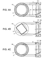
- Figs. 4A, 4B and 4C are diagrams each showing specific configuration of a shading member of the imaging apparatus according to Example 1.
- the shield member FS according to Example 1 is constructed by applying shield paint P on the periphery of the object side surface of the negative meniscus lens L11 forming a circular aperture portion O having an inner diameter ⁇ 1.
- a shield member FS according to the present application is not limited to this, any other configurations as shown in Fig. 4B and 4C may be used.
- a plate-like shield member Q having an aperture portion with rectangular shape projecting an external shape of effective pixels of the solid-state imaging device 7 onto the object side lens surface of the negative meniscus lens L11 may be disposed as the shield member FS in such a manner that the shield member Q is disposed inside of the lens barrel 2a holding the high zoom ratio zoom lens system, and comes in contact with the lens surface. With this configuration, it becomes possible to effectively prevent stray light from entering into the high zoom ratio zoom lens system.
- Example 1 as shown in Fig. 4C , when the inner diameter of an annular member R, such as a so-called retaining ring, which is screwed and fixed into the lens barrel 2a so as to fix the position of the negative meniscus lens L11 in a direction of the optical axis is made to be ⁇ 1, it becomes possible to make the annular member R function as a shield member FS.
- an annular member R having a high retaining ability is suitable for a large diameter lens.
- f denotes a focal length
- FNO denotes an f-number
- ⁇ 0 denoted an effective diameter of the negative meniscus lens L11
- ⁇ 1 denotes an inner diameter of the aperture portion O of the shield member FS, which is the maximum effective diameter of the negative meniscus lens L11 upon carrying out vibration reduction
- IH denotes a diagonal length of the solid-state imaging device from the center to a corner
- L denotes a total lens length of the high zoom ratio zoom lens system in a wide-angle end state
- ⁇ hw denotes the maximum moving amount of the solid-state imaging device 7 in the wide-angle end state
- ⁇ ht denotes the maximum moving amount of the solid-state imaging device 7 in the telephoto end state.
- surface shows the lens surface number counted in order from the object side
- r shows a radius of curvature
- d shows a distance to the next surface
- Bf denotes back focal length.
- E-n denotes " ⁇ 10 -n ".
- y denotes a vertical height from the optical axis
- X(y) denotes a sag amount which is a distance along the optical axis from the tangent surface at the vertex of the aspherical surface to the aspherical surface at the vertical height y from the optical axis
- r denotes a radius of curvature of a reference sphere
- ⁇ denotes a conical coefficient
- Cn denotes an aspherical coefficient of n-th order
- f denotes a focal length
- ⁇ denotes an imaging magnification
- D0 denotes a distance between an object and the object side surface of the negative meniscus lens L11 in the first lens group G1 (a photo-taking distance)
- Bf denotes a back focal length
- TL denotes a total lens length.
- mm is generally used for the unit of length such as the focal length, the radius of curvature and the like.
- the unit is not necessarily to be limited to "mm", and any other suitable unit can be used.
- Figs. 6A, 6B and 6C are graphs showing various aberrations of the high zoom ratio zoom lens system according to Example 1 upon focusing on infinity, in which Fig. 2A is in a wide-angle end state, Fig. 2B is in an intermediate focal length state, and Fig. 2C is in a telephoto end state.
- FNO denotes an f-number
- NA denotes a numerical aperture
- Y denotes an image height.
- the zoom lens system according to Example 1 shows superb optical performance as a result of good corrections to various aberrations in the wide-angle end state, in the intermediate focal length state, and in the telephoto end state upon focusing on infinity and on a close object.
- Example 2 The basic configuration of an imaging apparatus according to Example 2 is the same as Example 1, so that the duplicated explanations are omitted, and a high zoom ratio zoom lens system according to Example 2, which has different configuration from that of Example 1, is precisely explained below.
- Fig. 8 is diagram showing the high zoom ratio zoom lens system attached to the imaging apparatus according to Example 2 upon focusing on infinity in a wide-angle end state W, in an intermediate focal length state M, and in a telephoto end state T.
- the high zoom ratio zoom lens system according to Example 2 is composed of, in order from an object, a first lens group G1 having positive refractive power, a second lens group G2 having negative refractive power, an aperture stop S, a third lens group G3 having positive refractive power, a fourth lens group G4 having positive refractive power, a fifth lens group having positive refractive power, an optical low-pass filter LF, and a cover glass CG for a solid-state imaging device 7.
- the first lens group G1 is composed of, in order from the object, a cemented positive lens constructed by a negative meniscus lens L11 having a convex surface facing the object cemented with a positive meniscus lens L12 having a convex surface facing the object, and a positive meniscus lens L13 having a convex surface facing the object.
- the second lens group G2 is composed of, in order from the object, a negative meniscus lens L21 having a convex surface facing the object, and a cemented negative lens constructed by a double concave negative lens L22 cemented with a positive meniscus lens L23 having a convex surface facing the object.
- the third lens group G3 is composed of, in order from the object, a double convex positive lens L31, and a negative meniscus lens L32 having a concave surface facing the object.
- the fourth lens group G4 is composed of, in order from the object, a front group G4F having positive refractive power, and a rear group G4R having negative refractive power.
- the front group G4F is composed of a double convex positive lens L41 having an aspherical surface facing the image.
- the rear group G4R is composed of a cemented negative lens constructed by, in order from the object, a double convex positive lens L42 cemented with a double concave negative lens L43.
- the fifth lens group G5 is composed of a positive meniscus lens L51 having a convex surface facing the object.
- the first lens group G1 upon zooming from a wide-angle end state to a telephoto end state, the first lens group G1 is moved to the object, the second lens group G2 is moved at first to the image and then to the object, which has a zoom trajectory having a concave shape facing the object, the third lens group G3 is moved to the object, and the fourth lens group G4 is moved to the object.
- the aperture stop S is moved in a body with the third lens group G3.
- the fifth lens group G5 that is fixed upon zooming is move to the object.
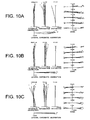
- Figs. 10A, 10B and 10C are graphs showing various aberrations of the high zoom ratio zoom lens system according to Example 2 upon focusing on infinity, in which Fig. 10A is in a wide-angle end state, Fig. 10B is in an intermediate focal length state, and Fig. 10C is in a telephoto end state.
- the zoom lens system according to Example 2 shows superb optical performance as a result of good corrections to various aberrations in the wide-angle end state, in the intermediate focal length state, and in the telephoto end state upon focusing on infinity and on a close object.
- any lens surface composing the high zoom ratio zoom lens system according to the present application may be an aspherical surface.
- the aspherical surface may be fabricated by a fine grinding process, a glass molding process that a glass material is formed into an aspherical shape by a mold, or a compound type process that a resin material is formed into an aspherical shape on a glass surface.
- An antireflection coating having high transmittance over a broad wavelength range may be applied to each lens surface of the high zoom ratio zoom lens system according to the present application to reduce flare or ghost images, so that high optical performance with a high contrast can be attained.
- each Example only shows an specific example of a high zoom ratio zoom lens system, so that the present invention is not limited to such Examples.
- an imaging apparatus an imaging method, and a high zoom ratio zoom lens carrying out vibration reduction by moving an imaging device in a direction substantially perpendicular to an optical axis, capable of efficiently using effective pixels of the solid-state imaging device, and capable of securing an excellent peripheral light quantity ratio of an object image even upon carrying out vibration reduction.
- a high zoom ration zoom lens system is suitable for an electronic still camera, and the like, capable of realizing a half angle of view of 4 degrees or less in a telephoto end state, an f-number in the telephoto end state of 6 or less, a zoom ratio of about 10, and compactness in the diameter of the lens barrel.
Abstract
Description
- The present invention relates to an imaging apparatus, an imaging method and a high zoom ratio zoom lens system.
- There has been proposed an imaging apparatus that reads out image information in a designated image frame as an object image from image information obtained by a solid-state imaging device, and is suitably changing the read out position of the designated image frame in accordance with variation in a position of the object image caused by a play of the lens barrel upon zooming a zoom lens system so as to correct the variation (for example, Japanese Patent Application Laid-Open No.
5-37849 - Moreover, there has been proposed an imaging apparatus capable of moving a solid-state imaging device in a direction along an optical axis in order to correct variation in an object image position along the optical axis caused upon zooming (for example, Japanese Patent Application Laid-Open No.
6-339054 - However, since the imaging apparatus disclosed in Japanese Patent Application Laid-Open No.
5-37849 - On the other hand, the imaging apparatus disclosed in Japanese Patent Application Laid-Open No.
6-339054 - The present invention is made in view of the aforementioned problems and has an object to provide an imaging apparatus, an imaging method, and a high zoom ratio zoom lens system carrying out vibration reduction by moving a solid-state imaging device in a direction substantially perpendicular to an optical axis, capable of efficiently using effective pixels of the solid-state imaging device, and capable of securing an excellent peripheral light quantity ratio of an object image even upon carrying out vibration reduction.
- According to a first aspect of the present invention, there is provided an imaging apparatus comprising: a high zoom ratio zoom lens system comprising, in order from an object, a first lens group having positive refractive power, a second lens group having negative refractive power, a third lens group, a fourth lens group, and a fifth lens group, upon zooming from a wide-angle end state to a telephoto end state, the first lens group, the second lens group, the third lens group, and the fourth lens group being moved along an optical axis; a solid-state imaging device capturing an object image formed by the high zoom ratio zoom lens system; a detecting member that detects variation in a position of the object image; a driving member that moves the solid-state imaging device in a direction substantially perpendicular to the optical axis; a control member that controls the driving member in order to correct variation in the position of the object image; and a shield member with an aperture portion for limiting bundle of rays incident on the periphery of the most object side lens in the first lens group of the high zoom ratio zoom lens system; and the following conditional expression being satisfied:

- According to a second aspect of the present invention, there is provided an imaging method for capturing an object image formed by a high zoom ratio zoom lens system by means of a solid-state imaging device with detecting variation in a position of the object image, and moving the solid-state imaging device in a direction substantially perpendicular to the optical axis so as to correct variation in the position of the object image, the imaging method comprising steps of: providing the high zoom ratio zoom lens system comprising, in order from the object, a first lens group having positive refractive power, a second lens group having negative refractive power, a third lens group, a fourth lens group, and a fifth lens group, upon zooming from a wide-angle end state to a telephoto end state, the first lens group, the second lens group, the third lens group, and the fourth lens group being moved along the optical axis; limiting bundle of rays incident on the periphery of the most object side lens in the first lens group of the high zoom ratio zoom lens system by a shield member with an aperture portion; and satisfying the following conditional expression:

- According to the present invention, it becomes possible to provide an imaging apparatus, an imaging method, and a high zoom ratio zoom lens system carrying out vibration reduction by moving a solid-state imaging device in a direction substantially perpendicular to an optical axis, capable of efficiently using effective pixels of the solid-state imaging device, and capable of securing an excellent peripheral light quantity ratio of an object image even upon carrying out vibration reduction.
-
-
Fig. 1 is a diagram showing an imaging apparatus according to Example 1 of the present application. -
Fig. 2 is a diagram showing lens configuration of a high zoom ratio zoom lens system attached to the imaging apparatus according to Example 1 together with a movement of an imaging device. -
Fig. 3 is diagram showing the high zoom ratio zoom lens system attached to the imaging apparatus according to Example 1 upon focusing on infinity in a wide-angle end state W, in an intermediate focal length state M, and in a telephoto end state T. -
Figs. 4A, 4B and 4C are diagrams each showing specific configuration of a shading member of the imaging apparatus according to Example 1. -
Figs. 5A, 5B and 5C are graphs showing light amount distribution on the object image in the wide-angle end state upon focusing on infinity in Example 1, in whichFig. 5A shows without vibration reduction (Φ1-Φ0=2.0mm),Fig. 5B shows upon carrying out maximum vibration reduction (Φ1-Φ=0.0mm), andFig. 5C shows upon carrying out maximum vibration reduction (Φ1-Φ0=2.0mm). -
Figs. 6A, 6B and 6C are graphs showing various aberrations of the high zoom ratio zoom lens system according to Example 1 upon focusing on infinity, in whichFig. 2A is in a wide-angle end state,Fig. 2B is in an intermediate focal length state, andFig. 2C is in a telephoto end state. -
Figs. 7A, 7B and 7C are graphs showing various aberrations of the high zoom ratio zoom lens system according to Example 1 upon focusing on a close object, in whichFig. 7A is in the wide-angle end state (Rw=300mm),Fig. 7B is in the intermediate focal length state (Rm=300mm), andFig. 7C is in the telephoto end state (Rt=1000mm). -
Fig. 8 is diagram showing the high zoom ratio zoom lens system attached to the imaging apparatus according to Example 2 upon focusing on infinity in a wide-angle end state W, in an intermediate focal length state M, and in a telephoto end state T. -
Figs. 9A, 9B and 9C are graphs showing light amount distribution on the object image in the wide-angle end state upon focusing on infinity in Example 2, in whichFig. 9A shows without vibration reduction (Φ1-Φ0=0.4mm),Fig. 9B shows upon carrying out maximum vibration reduction (Φ1-Φ0=0.0mm), andFig. 9C shows upon carrying out maximum vibration reduction (Φ1-Φ0=0.4mm). -
Figs. 10A, 10B and 10C are graphs showing various aberrations of the high zoom ratio zoom lens system according to Example 2 upon focusing on infinity, in whichFig. 10A is in a wide-angle end state,Fig. 10B is in an intermediate focal length state, andFig. 10C is in a telephoto end state. -
Figs. 11A, 11B and 11C are graphs showing various aberrations of the high zoom ratio zoom lens system according to Example 2 upon focusing on a close object, in whichFig. 11A is in the wide-angle end state (Rw=300mm),Fig. 11B is in the intermediate focal length state (Rm=300mm), andFig. 11C is in the telephoto end state (Rt=1000mm). - An imaging apparatus, an imaging method, and a high zoom ratio zoom lens system according to the present application are explained below with reference to accompanying drawings.
- An imaging apparatus according to the present application including: a high zoom ratio zoom lens system comprising, in order from an object, a first lens group having positive refractive power, a second lens group having negative refractive power, a third lens group having positive refractive power, a fourth lens group having positive refractive power, and a fifth lens group having positive refractive power, upon zooming from a wide-angle end state to a telephoto end state, the first lens group, the second lens group, the third lens group, and the fourth lens group being moved along an optical axis; a solid-state imaging device capturing an object image formed by the high zoom ratio zoom lens system; a detecting member that detects variation in a position of the object image; a driving member that moves the solid-state imaging device in a direction substantially perpendicular to the optical axis; a control member that controls the driving member in order to correct variation in the position of the object image; and a shield member with an aperture portion for limiting bundle of rays incident on the periphery of the most object side lens in the first lens group of the high zoom ratio zoom lens system; and the following conditional expression (1) being satisfied:

- With making refractive power of the third lens group positive, that of the fourth lens group positive, and that of the fifth lens group positive, it becomes possible to further secure the effect of the present application.
- Conditional expression (1) defines the diameter of the aperture portion in the shield member.
- When the value {L×(Δht/ft)}/(Φ1-Φ0) is equal to or falls below the lower limit of conditional expression (1), coma on the periphery of the image becomes large, so that it is undesirable. In order to secure the effect of the present application, it is preferable to set the lower limit of conditional expression (1) to 0.15.
- On the other hand, when the value {L×(Δht/ft)}/(Φ1-Φ0) is equal to or exceeds the upper limit of conditional expression (1), light quantity on the periphery of the image becomes uneven, so that it is undesirable. Moreover, when the maximum moving amount (a vibration reduction correction amount) of the solid-state imaging device in the telephoto end state is maximum, variation in the image plane becomes large, and variation in curvature of field is generated, so that it is undesirable. In order to further secure the effect of the present application, it is preferable to set the upper limit of conditional expression (1) to 1.50.
- In an imaging apparatus according to the present application, the aperture portion of the shield member is preferably an aperture having a circular shape.
- With this construction, since the aperture portion has a rotational symmetry centered on the optical axis, desired shield effect can be obtained without performing rotational adjustment. Incidentally, the inner diameter of the aperture portion having a circular shape becomes Φ1 in conditional expression (1).
- In an imaging apparatus according to the present application, the aperture portion of the shield member is preferably an aperture having a rectangular shape corresponding to the solid-state imaging device.
- With this construction, it becomes possible to set the shape of the aperture portion of the shield member to be an external shape of effective pixels of the solid-state imaging device projected on the most object side lens surface in the first lens group. Accordingly, it becomes possible to effectively prevent stray light from entering into the high zoom ratio zoom lens system. The diagonal length of the aperture portion having a rectangular shape becomes Φ1 in conditional expression (1).
- In an imaging apparatus according to the present application, the following conditional expression (2) is preferably satisfied:

- Conditional expression (2) defines an appropriate range of the maximum moving amount of the solid-state imaging device and a focal length of the high zoom ratio zoom lens system.
- When the value (fw×Δht)/(ft×Δhw) exceeds the upper limit of conditional expression (2), variation in the image plane becomes large in the case when the maximum moving amount of the solid-state imaging device become maximum. Moreover, variation in curvature of field is generated, so that it is undesirable. In order to secure the effect of the present application, it is preferable to set the upper limit of conditional expression (2) to 0.9.
- On the other hand, when the value (fw×Δht)/(ft×Δhw) is equal to or falls below the lower limit of conditional expression (2), the effective diameter of the most object side lens in the first lens group becomes too large, so that it is undesirable. In order to keep the effective diameter small, refractive power of the third lens group has to be large. As a result, coma becomes large, so that it is undesirable. In order to secure the effect of the present application, it is preferable to set the lower limit of conditional expression (2) to 0.2.
- In an imaging apparatus according to the present application, it is preferable that the shield member is made up by applying shielding paint on the most object side lens surface of the first lens group.
- As described above, with making up the shield member by applying shielding paint on the outer periphery of the most object side lens surface of the first lens group, it becomes possible to make the diameter of the aperture portion of the shield member small. Moreover, it becomes possible to make the number of assembly parts of the high zoom ratio zoom lens system fewer, so that cost reduction can be attained.
- In an imaging apparatus according to the present application, the shield member is preferably a plate-like member disposed on the most object side lens surface of the first lens group of the high zoom ratio zoom lens system.
- With this construction, it becomes possible to make the diameter of the aperture portion of the shield member small. The above-described plate-like member includes a thin sheet member.
- In an imaging apparatus according to the present application, the shield member is preferably formed in a body with a lens-fixing member for fixing the most object side lens of the first lens group in the high zoom ratio zoom lens system.
- With this construction, since an annular fixing member for being screwed and fixing the most object side lens of the first lens group into a lens barrel can be used as the shield member, the number of assembly parts can be fewer, so that the high zoom ratio zoom lens system can be simplified.
- In an imaging apparatus according to the present application, the high zoom ratio zoom lens system preferably carries out focusing by moving the fifth lens group along the optical axis.
- In this manner, with such configuration that focusing is carried out by the fifth lens group, which is fixed upon zooming, driving mechanism can be simplified.
- In an imaging apparatus according to the present application, in order to keep excellent aberration correction state with reducing the diameter of the shield member, the fourth lens group of the high zoom ratio zoom lens system is preferably composed of, in order from the object, a front group having positive refractive power, and a rear group having negative refractive power, and the following conditional expression (3) is preferably satisfied:

- Conditional expression (3) defines an appropriate range of the focal lengths of the front group and rear group of the fourth lens group.
- When the value (f4F+f4R)/f4 is equal to or exceeds the upper limit of conditional expression (3), inner coma is generated in an intermediate focal length state, so that it is undesirable. In order to secure the effect of the present application and to excellently suppress generation of inner coma in the intermediate focal length state, it is preferable to set the upper limit of conditional expression (3) to -0.25.
- On the other hand, when the value (f4F+f4R)/f4 is equal to or falls below the lower limit of conditional expression (3), the diameter of the aperture portion of the shield member becomes large, so that it is undesirable. In order to secure the effect of the present application, it is preferable to set the lower limit of conditional expression (3) to -0.40.
- An imaging method for capturing an object image formed by a high zoom ratio zoom lens system by means of a solid-state imaging device with detecting variation in a position of the object image, and moving the solid-state imaging device in a direction substantially perpendicular to the optical axis so as to correct variation in the position of the object image, the imaging method comprising steps of: providing the high zoom ratio zoom lens comprising, in order from the object, a first lens group having positive refractive power, a second lens group having negative refractive power, a third lens group, a fourth lens group, and a fifth lens group, upon zooming from a wide-angle end state to a telephoto end state, the first lens group, the second lens group, the third lens group, and the fourth lens group being moved along the optical axis; limiting bundle of rays incident on the periphery of the most object side lens in the first lens group of the high zoom ratio zoom lens system by a shield member with an aperture portion; and satisfying the following conditional expression:

- With this construction, it becomes possible to realize an imaging method carrying out vibration reduction by moving an imaging device in a direction substantially perpendicular to an optical axis, capable of efficiently using effective pixels of the solid-state imaging device, and capable of securing an excellent peripheral light quantity ratio of a shot image even upon carrying out vibration reduction.
- A high zoom ratio zoom lens system according to the present application that is used as an image-taking lens of an imaging apparatus having a configuration that upon capturing an object image formed by the image-taking lens by means of a solid-state imaging device, variation in a position of the object image is detected, and in order to correct variation in the position of the object image the solid-state imaging device is moved in a direction substantially perpendicular to an optical axis, the high zoom ratio zoom lens system comprising, in order from the object: a first lens group having positive refractive power; a second lens group having negative refractive power; a third lens group; a fourth lens group; and a fifth lens group, upon zooming from a wide-angle end state to a telephoto end state, the first lens group, the second lens group, the third lens group and the fourth lens group being moved along the optical axis, a shield member with an aperture portion for limiting bundle of rays incident on the periphery of the most object side lens in the first lens group being disposed, and the following conditional expression (1) being satisfied:

- With this construction, it becomes possible to realize a high zoom ratio zoom lens system carrying out vibration reduction by moving an imaging device in a direction substantially perpendicular to an optical axis, capable of efficiently using effective pixels of the solid-state imaging device, and capable of securing an excellent peripheral light quantity ratio of a shot image even upon carrying out vibration reduction.
- An imaging apparatus according to the present application is explained below with reference to accompanying drawings.
-
Fig. 1 is a diagram showing an imaging apparatus according to Example 1 of the present application. - As shown in
Fig. 1 , theimaging apparatus 1 is a single-lens reflex digital camera equipped with a high zoom ratio zoom lens system explained later as an image-taking lens. - In the
imaging apparatus 1, light emitted from an object (not shown) is converged by a high zoom ratiozoom lens system 2, and focused on a focusingscreen 4 through aquick return mirror 3. The object image focused on the focusingscreen 4 is reflected a plurality of times by apentagonal roof prism 5, and led to aneyepiece 6. Therefore, a photographer can observe the object image as an erected image through theeyepiece 6. - When the photographer presses a shutter release button (not shown), the
quick return mirror 3 is removed from an optical path, and the light from the object (not shown) reaches a solid-state imaging device 7. Accordingly, light from the object is captured by the solid-state imaging device 7 and stored in amemory 8 as an object image. In this manner, the photographer can take a picture of the object by theimaging apparatus 1. - In addition to the above-described solid-
state imaging device 7 for capturing the object image formed by the high zoom ratiozoom lens system 2, theimaging apparatus 1 includes a camera-shake detector 9 for detecting an image blur, in other words, variation in the position of the object image caused by a camera shake of a user of theimaging apparatus 1, adriver 10 for moving the solid-state imaging device 7 in a direction substantially perpendicular to the optical axis, and acontroller 11 for controlling each member of theimaging apparatus 1 such as thedriver 10 so as to correcting variation in the position of the object image. - In the
imaging apparatus 1 described above, at first variation in the position of the object image is detected by the camera-shake detector 9. Then, thecontroller 11 controls thedriver 10 on the basis of the detected signal of the camera-shake detector 9 to move the solid-state imaging device 7 in a direction substantially perpendicular to the optical axis. Accordingly, variation in the position of the object image can be corrected. In this manner, vibration reduction of theimaging apparatus 1 is realized, and a failure in shooting caused by a camera shake can be prevented. - Then, a high zoom ratio zoom lens system, which is the most specific feature of Example 1, is explained.
-
Fig. 2 is a diagram showing lens configuration of a high zoom ratio zoom lens system attached to the imaging apparatus according to Example 1 together with a movement of an imaging device. -
Fig. 3 is diagram showing the high zoom ratio zoom lens system attached to the imaging apparatus according to Example 1 upon focusing on infinity in a wide-angle end state W, in an intermediate focal length state M, and in a telephoto end state T. - The high zoom ratio zoom lens system according to Example 1 is composed of, in order from an object, a first lens group G1 having positive refractive power, a second lens group G2 having negative refractive power, an aperture stop S, a third lens group G3 having positive refractive power, a fourth lens group G4 having positive refractive power, a fifth lens group G5 having positive refractive power, an optical low-pass filter LF, and a cover glass CG for the solid-
state imaging device 7. - The first lens group G1 is composed of, in order from the object, a cemented positive lens constructed by a negative meniscus lens L11 having a convex surface facing the object cemented with a positive meniscus lens L12 having a convex surface facing the object, and a positive meniscus lens L13 having a convex surface facing the object.
- The second lens group G2 is composed of, in order from the object, a negative meniscus lens L21 having a convex surface facing the object, and a cemented negative lens constructed by a double concave negative lens L22 cemented with a double convex positive lens L23.
- The third lens group G3 is composed of, in order from the object, a double convex positive lens L31, and a negative meniscus lens L32 having a concave surface facing the object.
- The fourth lens group G4 is composed of, in order from the object, a front group G4F having positive refractive power, and a rear group G4R having negative refractive power. The front group G4F is composed of a double convex positive lens L41 having an aspherical surface facing an image. The rear group G4R is composed of a cemented negative lens constructed by, in order from the object, a double convex positive lens L42 cemented with a double concave negative lens L43.
- The fifth lens group G5 is composed of a positive meniscus lens L51 having a convex surface facing the object.
- In a high zoom ratio zoom lens system according to Example 1, upon zooming from a wide-angle end state to a telephoto end state, the first lens group G1 is moved to the object, the second lens group G2 is moved at first to the image and then to the object which has a zoom trajectory with a concave shape facing the object, the third lens group G3 is moved to the object, and the fourth lens group G4 is moved to the object. On this occasion, the aperture stop S is moved in a body with the third lens group G3.
- In a high zoom ratio zoom lens system according to Example 1, upon focusing from infinity to a close object, the fifth lens group that is fixed upon zooming is moved to the object.
- In a high zoom ratio zoom lens system having such construction, a shield member FS having a circular aperture portion O is disposed in the vicinity of the object side lens surface of the negative meniscus lens L11, which is the most object side lens in the first lens group G1, in order to shield unnecessary bundle of rays incident on the periphery of the lens surface.
- In the aperture portion O of the shield member FS, the inner diameter Φ1 is larger than the effective diameter Φ0 of the negative meniscus lens L11, and the above-described conditional expression (1) is satisfied. With this configuration, it becomes possible to excellently secure peripheral light quantity ratio of the object image with shielding unnecessary bundle of rays incident on the periphery of the lens surface even upon carrying out vibration reduction in the
imaging apparatus 1 by moving the solid-state imaging device 7 in a direction substantially perpendicular to the optical axis. -
Figs. 4A, 4B and 4C are diagrams each showing specific configuration of a shading member of the imaging apparatus according to Example 1. - As shown in
Fig. 4A , the shield member FS according to Example 1 is constructed by applying shield paint P on the periphery of the object side surface of the negative meniscus lens L11 forming a circular aperture portion O having an inner diameter Φ1. - Here, a shield member FS according to the present application is not limited to this, any other configurations as shown in
Fig. 4B and 4C may be used. - Moreover, as shown in
Fig. 4B , a plate-like shield member Q having an aperture portion with rectangular shape projecting an external shape of effective pixels of the solid-state imaging device 7 onto the object side lens surface of the negative meniscus lens L11 may be disposed as the shield member FS in such a manner that the shield member Q is disposed inside of thelens barrel 2a holding the high zoom ratio zoom lens system, and comes in contact with the lens surface. With this configuration, it becomes possible to effectively prevent stray light from entering into the high zoom ratio zoom lens system. - Furthermore, in Example 1, as shown in
Fig. 4C , when the inner diameter of an annular member R, such as a so-called retaining ring, which is screwed and fixed into thelens barrel 2a so as to fix the position of the negative meniscus lens L11 in a direction of the optical axis is made to be Φ1, it becomes possible to make the annular member R function as a shield member FS. Such an annular member R having a high retaining ability is suitable for a large diameter lens. - Then, specific numerical data of a high zoom ratio zoom lens system according to Example 1 are shown below.
- Various values associated with a high zoom ratio zoom lens system according to Example 1 are listed in Table 1.
- In [Specifications], f denotes a focal length, FNO denotes an f-number, Φ0 denoted an effective diameter of the negative meniscus lens L11, Φ1 denotes an inner diameter of the aperture portion O of the shield member FS, which is the maximum effective diameter of the negative meniscus lens L11 upon carrying out vibration reduction, IH denotes a diagonal length of the solid-state imaging device from the center to a corner, L denotes a total lens length of the high zoom ratio zoom lens system in a wide-angle end state, Δhw denotes the maximum moving amount of the solid-
state imaging device 7 in the wide-angle end state, Δht denotes the maximum moving amount of the solid-state imaging device 7 in the telephoto end state. - In [Lens Data], "surface" shows the lens surface number counted in order from the object side, "r" shows a radius of curvature, "d" shows a distance to the next surface, "νd" shows Abbe number at d-line (wavelength λ=587.6nm), and "nd" shows refractive index at d-line (wavelength λ=587.6nm). Moreover, r=0.0000 denotes a plane surface, and Bf denotes back focal length. Refractive index of the air nd=1.000000 is omitted.
- In [Aspherical Data], "E-n" denotes "×10-n". A rotationally symmetrical aspherical surface is exhibited by the following expression:

- In [Variable Distances], f denotes a focal length, β denotes an imaging magnification, D0 denotes a distance between an object and the object side surface of the negative meniscus lens L11 in the first lens group G1 (a photo-taking distance), Bf denotes a back focal length, and TL denotes a total lens length.
- In the tables for various values, "mm" is generally used for the unit of length such as the focal length, the radius of curvature and the like. However, since similar optical performance can be obtained by an optical system proportionally enlarged or reduced its dimension, the unit is not necessarily to be limited to "mm", and any other suitable unit can be used.
- The explanation of reference symbols is the same in the other Examples.
Table 1 [Specifications] W T f= 6.36 60.00 FNO= 2.6 5.4 Φ0= 22.0 Φ1= 24.0 IH= 3.52 L= 74.1 Δhw= 0.150 Δht= 0.314 [Lens Data] surface r d νd nd 1) 49.9711 1.2000 23.78 1.846660 2) 29.4301 3.3000 55.53 1.696797 3) 5378.9855 0.1000 4) 33.8916 2.3000 82.56 1.497820 5) 117.7111 (d5) 6) 411.5528 1.0000 40.76 1.882997 7) 9.1748 2.8000 8) -14.4058 1.0000 61.14 1.589130 9) 10.8161 2.3000 22.76 1.808095 10) -352.1299 (d10) 11) 0.0000 0.5000 Aperture Stop S 12) 14.2018 2.3000 60.67 1.563839 13) -19.3736 1.4000 14) -12.1858 1.0000 23.78 1.846660 15) -32.4283 (d15) 16) 103.3476 2.2000 40.87 1.804320 17) -16.9719 0.1000 18) 8.5267 3.6000 82.56 1.497820 19) -17.5207 1.1000 40.76 1.882997 20) 9.6921 (d20) 21) 14.2621 1.9000 48.84 1.531717 22) 75.3615 (d22) 23) 0.0000 1.6000 70.51 1.544370 24) 0.0000 0.5000 25) 0.0000 0.5000 64.10 1.516800 26) 0.0000 Bf [Aspherical Data] Surface Number: 17 κ= -0.1290 C4= 0.00000E+00 C6= -1.77080E-07 C8= 1.51460E-09 [Variable Distances] (Upon focusing on infinity) W M T f 6.36000 28.00000 60.00000 D0 ∞ ∞ ∞ d5 1.58729 15.69746 22.06330 d10 22.98517 7.63292 2.74873 d15 9.89944 5.01384 3.95498 d20 2.90783 18.06457 26.11013 d22 5.00000 5.00000 5.00000 Bf 1.02477 1.02477 1.02477 TL 74.10449 83.13355 91.60191 (Upon focusing on close object) W M T β -0.02598 -0.09576 -0.05429 D0 225.8955 216.8664 908.3982 d5 1.58729 15.69746 22.06330 d10 22.98517 7.63292 2.74873 d15 9.89944 5.01384 3.95498 d20 2.57693 13.52669 20.75771 d22 5.33090 9.53788 10.35242 Bf 1.02477 1.02477 1.02477 TL 74.10449 83.13355 91.60191 [Values for Conditional Expressions] (1) : {L×(Δht/ft)}/(Φ1-Φ0)= 0.19 (2) : (fw×Δht)/(ft×Δhw)= 0.22 (3) : (f4F+f4R)/f4= -0.326 -
Figs. 5A, 5B and 5C are graphs showing light amount distribution on the object image in the wide-angle end state upon focusing on infinity in Example 1, in whichFig. 5A shows without vibration reduction (Φ1-Φ0=2.0mm),Fig. 5B shows upon carrying out maximum vibration reduction (Φ1-Φ0=0.0mm), andFig. 5C shows upon carrying out maximum vibration reduction (Φ1-Φ0=2.0mm). - As is apparent from
Figs. 5A, 5B and 5C , when the value Φ1-Φ0 is kept relatively large value in the vicinity of the lower limit of conditional expression (1), light amount on the corner of the image frame becomes excellent. -
Figs. 6A, 6B and 6C are graphs showing various aberrations of the high zoom ratio zoom lens system according to Example 1 upon focusing on infinity, in whichFig. 2A is in a wide-angle end state,Fig. 2B is in an intermediate focal length state, andFig. 2C is in a telephoto end state. -
Figs. 7A, 7B and 7C are graphs showing various aberrations of the high zoom ratio zoom lens system according to Example 1 upon focusing on a close object, in whichFig. 7A is in the wide-angle end state (Rw=300mm),Fig. 7B is in the intermediate focal length state (Rm=300mm), andFig. 7C is in the telephoto end state (Rt=1000mm). - In respective graphs, FNO denotes an f-number, NA denotes a numerical aperture, Y denotes an image height. In respective graphs, d denotes an aberration curve at d-line (wavelength λ=587.6nm), g denotes an aberration curve at g-line (wavelength λ=435.8nm), C denotes an aberration curve at C-line (wavelength λ=656.3nm), and F denotes an aberration curve at F-line (wavelength λ=486.1nm).
- In graphs showing spherical aberration, an f-number or a numerical aperture with respect to the maximum aperture is shown. In graphs showing coma, coma with respect to each image height is shown. In the graph showing astigmatism, a solid line indicates a sagittal image plane, and a broken line indicates a meridional image plane. The above-described explanation regarding various aberration graphs is the same as the other Examples.
- As is apparent from the respective graphs, the zoom lens system according to Example 1 shows superb optical performance as a result of good corrections to various aberrations in the wide-angle end state, in the intermediate focal length state, and in the telephoto end state upon focusing on infinity and on a close object.
- The basic configuration of an imaging apparatus according to Example 2 is the same as Example 1, so that the duplicated explanations are omitted, and a high zoom ratio zoom lens system according to Example 2, which has different configuration from that of Example 1, is precisely explained below.
-
Fig. 8 is diagram showing the high zoom ratio zoom lens system attached to the imaging apparatus according to Example 2 upon focusing on infinity in a wide-angle end state W, in an intermediate focal length state M, and in a telephoto end state T. - The high zoom ratio zoom lens system according to Example 2 is composed of, in order from an object, a first lens group G1 having positive refractive power, a second lens group G2 having negative refractive power, an aperture stop S, a third lens group G3 having positive refractive power, a fourth lens group G4 having positive refractive power, a fifth lens group having positive refractive power, an optical low-pass filter LF, and a cover glass CG for a solid-
state imaging device 7. - The first lens group G1 is composed of, in order from the object, a cemented positive lens constructed by a negative meniscus lens L11 having a convex surface facing the object cemented with a positive meniscus lens L12 having a convex surface facing the object, and a positive meniscus lens L13 having a convex surface facing the object.
- The second lens group G2 is composed of, in order from the object, a negative meniscus lens L21 having a convex surface facing the object, and a cemented negative lens constructed by a double concave negative lens L22 cemented with a positive meniscus lens L23 having a convex surface facing the object.
- The third lens group G3 is composed of, in order from the object, a double convex positive lens L31, and a negative meniscus lens L32 having a concave surface facing the object.
- The fourth lens group G4 is composed of, in order from the object, a front group G4F having positive refractive power, and a rear group G4R having negative refractive power. The front group G4F is composed of a double convex positive lens L41 having an aspherical surface facing the image. The rear group G4R is composed of a cemented negative lens constructed by, in order from the object, a double convex positive lens L42 cemented with a double concave negative lens L43.
- The fifth lens group G5 is composed of a positive meniscus lens L51 having a convex surface facing the object.
- In the high zoom ratio zoom lens system according to Example 2, upon zooming from a wide-angle end state to a telephoto end state, the first lens group G1 is moved to the object, the second lens group G2 is moved at first to the image and then to the object, which has a zoom trajectory having a concave shape facing the object, the third lens group G3 is moved to the object, and the fourth lens group G4 is moved to the object. On this occasion, the aperture stop S is moved in a body with the third lens group G3.
- In the high zoom ratio zoom lens system according to Example 2, upon focusing from infinity to a close object, the fifth lens group G5 that is fixed upon zooming is move to the object.
- Various values associated with the high zoom ratio zoom lens system according to Example 2 are listed in Table 2.
Table 2 [Specifications] W T f= 6.36 60.00 FNO= 2.7 5.9 Φ0= 21.8 Φ1= 22.2 IH= 3.52 L= 75.3 Δhw= 0.040 Δht= 0.314 [Lens Data] surface r d νd nd 1) 55.0652 1.2000 33.89 1.803840 2) 23.7762 3.6000 55.53 1.696797 3) 215.8744 0.1000 4) 36.5812 2.3000 82.56 1.497820 5) 2497.9174 (d5) 6) 60.2908 1.2000 40.76 1.882997 7) 8.5204 3.3000 8) -12.7297 1.1000 64.10 1.516800 9) 10.7779 2.4000 22.76 1.808095 10) 135.4699 (d10) 11) 0.5000 Aperture Stop S 12) 14.1390 2.3000 82.52 1.497820 13) -19.3654 2.6000 14) -10.6233 1.1000 23.78 1.846660 15) -19.0400 (d15) 16) 68.4505 2.2000 40.87 1.804320 17) -18.2949 0.1000 18) 9.1400 3.6000 82.56 1.497820 19) -19.6293 1.1000 40.76 1.882997 20) 9.7796 (d20) 21) 12.6808 1.9000 48.84 1.531717 22) 48.0770 (d22) 23) 0.0000 1.6000 70.51 1.544370 24) 0.0000 0.5000 25) 0.0000 0.5000 64.10 1.516800 26) 0.0000 Bf [Aspherical Data] Surface Number: 8 κ= 1.4722 C4= 0.00000E+00 C6= -1.17080E-06 C8= 5.18160E-09 Surface Number: 17 κ= -0.2417 C4= 0.00000E+00 C6= -8.07840E-08 C8= 1.57540E-10 [Variable Distances] (Upon focusing on infinity) W M T f 6.36000 28.00000 60.00000 D0 ∞ ∞ ∞ d5 1.53220 16.37499 22.66404 d10 22.72841 7.26469 2.92108 d15 9.23659 4.47495 3.24643 d20 2.52172 20.12208 33.21485 d22 5.20000 5.20000 5.20000 Bf 0.83352 0.83352 0.83352 TL 75.25244 87.47022 101.27992 (Upon focusing on close object) W M T β -0.02607 -0.09698 -0.05408 D0 224.7476 212.5298 898.7201 d5 1.53220 16.37499 22.66404 d10 22.72841 7.26469 2.92108 d15 9.23659 4.47495 3.24643 d20 2.20140 15.66133 28.02150 d22 5.52032 9.66074 10.39335 Bf 0.83352 0.83352 0.83352 TL 75.25244 87.47022 101.27992 [Values for Conditional Expressions] (1):{ L×(Δht/ft)}/(Φ1-Φ0)= 0.985 (2): (fw×Δht)/(ft×Δhw)= 0.84 (3): (f4F+f4R)/f4= -0.26 -
Figs. 9A, 9B and 9C are graphs showing light amount distribution on the object image in the wide-angle end state upon focusing on infinity in Example 2, in whichFig. 9A shows without vibration reduction (Φ1-Φ0=0.4mm),Fig. 9B shows upon carrying out maximum vibration reduction (Φ1-Φ0=0.0mm), andFig. 9C shows upon carrying out maximum vibration reduction (Φ1-Φ0=0.4mm). - As shown in
Figs. 9A, 9B and 9C , even if the value Φ1-Φ0=0.0mm in the vicinity of the upper limit of conditional expression (1), since variation in light amount ratio is small as shown inFig. 9B , light amount on the corner of the image frame becomes excellent. -
Figs. 10A, 10B and 10C are graphs showing various aberrations of the high zoom ratio zoom lens system according to Example 2 upon focusing on infinity, in whichFig. 10A is in a wide-angle end state,Fig. 10B is in an intermediate focal length state, andFig. 10C is in a telephoto end state. -
Figs. 11A, 11B and 11C are graphs showing various aberrations of the high zoom ratio zoom lens system according to Example 2 upon focusing on a close object, in whichFig. 11A is in the wide-angle end state (Rw=300mm),Fig. 11B is in the intermediate focal length state (Rm=300mm), andFig. 11C is in the telephoto end state (Rt=1000mm). - As is apparent from the respective graphs, the zoom lens system according to Example 2 shows superb optical performance as a result of good corrections to various aberrations in the wide-angle end state, in the intermediate focal length state, and in the telephoto end state upon focusing on infinity and on a close object.
- It is needless to say that although a high zoom ratio zoom lens system with a five-lens-group configuration is shown as each Example of the present application, a zoom lens system simply added by a lens group to the five-lens-group configuration is included in the scope of the present invention as set out by the appended claims.
- Moreover, any lens surface composing the high zoom ratio zoom lens system according to the present application may be an aspherical surface. The aspherical surface may be fabricated by a fine grinding process, a glass molding process that a glass material is formed into an aspherical shape by a mold, or a compound type process that a resin material is formed into an aspherical shape on a glass surface.
- An antireflection coating having high transmittance over a broad wavelength range may be applied to each lens surface of the high zoom ratio zoom lens system according to the present application to reduce flare or ghost images, so that high optical performance with a high contrast can be attained.
- The above-described each Example only shows an specific example of a high zoom ratio zoom lens system, so that the present invention is not limited to such Examples.
- According to each example of the present application, it becomes possible to provide an imaging apparatus, an imaging method, and a high zoom ratio zoom lens carrying out vibration reduction by moving an imaging device in a direction substantially perpendicular to an optical axis, capable of efficiently using effective pixels of the solid-state imaging device, and capable of securing an excellent peripheral light quantity ratio of an object image even upon carrying out vibration reduction.
- Moreover, a high zoom ration zoom lens system according to the present application is suitable for an electronic still camera, and the like, capable of realizing a half angle of view of 4 degrees or less in a telephoto end state, an f-number in the telephoto end state of 6 or less, a zoom ratio of about 10, and compactness in the diameter of the lens barrel.
Claims (13)
- An imaging apparatus (1) comprising:a high zoom ratio zoom lens system (2) comprising, in order from an object side, a first lens group (G1) having positive refractive power, a second lens group (G2) having negative refractive power, a third lens group (G3), a fourth lens group (G4), and a fifth lens group (G5), for zooming from the wide-angle end state to the telephoto end state, the first lens group (G1), the second lens group (G2), the third lens group (G3), and the fourth lens group (G4) being movable along the optical axis;a solid-state imaging device (7) arranged for capturing the image formed by the high zoom ratio zoom lens system (2);a detecting member (9) arranged for detecting variation in the position of the image;a driving member (10) arranged for moving the solid-state imaging device (7) in a direction substantially perpendicular to the optical axis;a control member (11) arranged for controlling the driving member (10) in order to correct variation in the position of the object image; anda shield member (FS) with an aperture portion (O) arranged for limiting bundle of rays incident on the periphery of the most object side lens in the first lens group (G1) of the high zoom ratio zoom lens system; andthe following conditional expression being satisfied:

- The imaging apparatus (1) according to claim 1, wherein the third lens group (G3) has positive refractive power, the fourth lens group (G4) has positive refractive power, and the fifth lens group (G5) has positive refractive power.
- The imaging apparatus (1) according to claim 1 or 2, wherein the following conditional expression is satisfied:

- The imaging apparatus (1) according to claim 1, 2 or 3, wherein the fourth lens group (G4) consists of, in order from the object side, a front group (GF) having positive refractive power, and a rear group (G4R) having negative refractive power, and the following conditional expression is satisfied:

- The imaging apparatus according to any preceding claim, wherein the aperture portion (O) in the shield member (FS) is a circular aperture.
- The imaging apparatus according to any of claims 1 to 5, wherein the aperture portion in the shield member is a rectangular aperture.
- The imaging apparatus according to any preceding claim, wherein the following conditional expression is satisfied:

- The imaging apparatus (1) according to any preceding claim, wherein the shield member (FS) is made up by applying shielding paint on the most object side lens surface of the first lens group (G1).
- The imaging apparatus (1) according to any of claims 1 to 7, wherein the shield member (FS) is a plate-like member disposed in the vicinity of the most object side lens surface of the first lens group (G1) in the high zoom ratio zoom lens system (2).
- The imaging apparatus (1) according to any of claims 1 to 7, wherein the shield member is formed in a body with a lens-fixing member for fixing the most object side lens of the first lens group in the high zoom ratio zoom lens system.
- The imaging apparatus (1) according to any preceding claim, wherein the high zoom ratio zoom lens system (2) carries out focusing by moving the fifth lens group (G5) along the optical axis.
- An imaging method for capturing an image formed by a high zoom ratio zoom lens system (2) by means of a solid-state imaging device (7) with detecting variation in the position of the image, and moving the solid-state imaging device (7) in a direction substantially perpendicular to the optical axis so as to correct the variation in the position of the image, the imaging method comprising steps of:providing the high zoom ratio zoom lens system (2) comprising, in order from the object side, a first lens group (G1) having positive refractive power, a second lens group (G2) having negative refractive power, a third lens group (G3), a fourth lens group (G4), and a fifth lens group (G5), upon zooming from the wide-angle end state to the telephoto end state, the first lens group (G1), the second lens group (G2), the third lens group (G3), and the fourth lens group (G4) being moved along the optical axis;limiting bundle of rays incident on the periphery of the most object side lens in the first lens group (G1) of the high zoom ratio zoom lens system (2) by a shield member (FS) with an aperture portion (O); andsatisfying the following conditional expression:

- The imaging method according to claim 12,
wherein the imaging apparatus is according to any of claims 2 to 11.
Applications Claiming Priority (2)
| Application Number | Priority Date | Filing Date | Title |
|---|---|---|---|
| JP2006099295 | 2006-03-31 | ||
| PCT/JP2007/053696 WO2007113952A1 (en) | 2006-03-31 | 2007-02-21 | Imaging device, imaging method, highly variable magnification zoom lens |
Publications (3)
| Publication Number | Publication Date |
|---|---|
| EP2003479A1 EP2003479A1 (en) | 2008-12-17 |
| EP2003479A4 EP2003479A4 (en) | 2009-07-15 |
| EP2003479B1 true EP2003479B1 (en) | 2010-12-29 |
Family
ID=38563225
Family Applications (1)
| Application Number | Title | Priority Date | Filing Date |
|---|---|---|---|
| EP07715031A Not-in-force EP2003479B1 (en) | 2006-03-31 | 2007-02-21 | Zoom lens of the telephoto type with a high zoom ratio |
Country Status (7)
| Country | Link |
|---|---|
| US (1) | US7843647B2 (en) |
| EP (1) | EP2003479B1 (en) |
| JP (1) | JP5071380B2 (en) |
| CN (1) | CN101395518B (en) |
| AT (1) | ATE493682T1 (en) |
| DE (1) | DE602007011584D1 (en) |
| WO (1) | WO2007113952A1 (en) |
Families Citing this family (15)
| Publication number | Priority date | Publication date | Assignee | Title |
|---|---|---|---|---|
| JP4813448B2 (en) * | 2007-11-16 | 2011-11-09 | 富士フイルム株式会社 | IMAGING SYSTEM, IMAGING DEVICE EQUIPPED WITH THIS IMAGING SYSTEM, PORTABLE TERMINAL DEVICE, IN-VEHICLE DEVICE, AND MEDICAL DEVICE |
| JP2009139697A (en) * | 2007-12-07 | 2009-06-25 | Fujinon Corp | Imaging system, and imaging apparatus, portable terminal apparatus, in-vehicle apparatus and medical apparatus with imaging system, and method for manufacturing imaging system |
| JP5154981B2 (en) * | 2008-03-10 | 2013-02-27 | オリンパスイメージング株式会社 | Image pickup apparatus having a zoom lens |
| JP5423235B2 (en) * | 2009-08-20 | 2014-02-19 | ソニー株式会社 | Imaging device |
| JP5293716B2 (en) * | 2010-09-30 | 2013-09-18 | 株式会社ニコン | Interchangeable lens, camera body and camera system |
| JP5734769B2 (en) * | 2011-06-28 | 2015-06-17 | シャープ株式会社 | Imaging lens and imaging module |
| TWI420143B (en) * | 2011-07-01 | 2013-12-21 | Asia Optical Co Inc | Zoom lens |
| CN103135195A (en) * | 2011-12-01 | 2013-06-05 | 佛山普立华科技有限公司 | Zoom lens and imaging device |
| CN103163637A (en) * | 2011-12-17 | 2013-06-19 | 鸿富锦精密工业(深圳)有限公司 | Zoom lens |
| CN103207446A (en) * | 2013-04-23 | 2013-07-17 | 中国科学院西安光学精密机械研究所 | Optical coupling system for glimmer detection |
| US9602727B2 (en) * | 2015-03-06 | 2017-03-21 | Panasonic Intellectual Property Management Co., Ltd. | Imaging apparatus and imaging method |
| US10171739B2 (en) * | 2016-03-02 | 2019-01-01 | Panasonic Intellectual Property Management Co., Ltd. | Image pickup device |
| US11209578B2 (en) | 2017-08-02 | 2021-12-28 | Sintai Optical (Shenzhen) Co., Ltd. | Camera device |
| TWI627439B (en) * | 2017-08-02 | 2018-06-21 | 信泰光學(深圳)有限公司 | Camera device |
| JP2021139973A (en) * | 2020-03-03 | 2021-09-16 | キヤノン株式会社 | Imaging apparatus, control method thereof, and imaging system |
Family Cites Families (12)
| Publication number | Priority date | Publication date | Assignee | Title |
|---|---|---|---|---|
| JP3153273B2 (en) | 1991-08-01 | 2001-04-03 | オリンパス光学工業株式会社 | camera |
| JPH06160779A (en) * | 1992-11-25 | 1994-06-07 | Canon Inc | Vibration proof optical system provided with variable apex angle prism device |
| JPH06339054A (en) * | 1993-05-31 | 1994-12-06 | Nikon Corp | Variable power image pickup device |
| US5587739A (en) | 1993-03-26 | 1996-12-24 | Nikon Corporation | Variable magnification image taking device |
| US5579171A (en) | 1993-03-30 | 1996-11-26 | Nikon Corporation | Zoom lens equipped with the image stabilizing function |
| JPH06289298A (en) * | 1993-03-30 | 1994-10-18 | Nikon Corp | Zoom lens with vibrationproofing function |
| JP2001337272A (en) * | 2000-05-26 | 2001-12-07 | Matsushita Electric Ind Co Ltd | Zoom lens incorporated with camera shake correcting function and video camera using the same |
| JP4288408B2 (en) * | 2003-02-20 | 2009-07-01 | 株式会社ニコン | Zoom lens with image shift |
| JP4606105B2 (en) * | 2004-09-24 | 2011-01-05 | Hoya株式会社 | Image blur correction device |
| JP4774710B2 (en) | 2004-09-30 | 2011-09-14 | 株式会社ニコン | Zoom lens |
| JP2007033879A (en) * | 2005-07-27 | 2007-02-08 | Sony Corp | Imaging lens device and imaging apparatus |
| US20080297901A1 (en) * | 2007-05-29 | 2008-12-04 | Nikon Corporation | Zoom lens system, optical apparatus, and method for forming an image |
-
2007
- 2007-02-21 EP EP07715031A patent/EP2003479B1/en not_active Not-in-force
- 2007-02-21 JP JP2008508461A patent/JP5071380B2/en not_active Expired - Fee Related
- 2007-02-21 DE DE602007011584T patent/DE602007011584D1/en active Active
- 2007-02-21 AT AT07715031T patent/ATE493682T1/en not_active IP Right Cessation
- 2007-02-21 US US12/160,568 patent/US7843647B2/en active Active
- 2007-02-21 CN CN2007800081558A patent/CN101395518B/en not_active Expired - Fee Related
- 2007-02-21 WO PCT/JP2007/053696 patent/WO2007113952A1/en active Application Filing
Also Published As
| Publication number | Publication date |
|---|---|
| CN101395518B (en) | 2012-01-25 |
| EP2003479A1 (en) | 2008-12-17 |
| JPWO2007113952A1 (en) | 2009-08-13 |
| WO2007113952A1 (en) | 2007-10-11 |
| US20100232032A1 (en) | 2010-09-16 |
| CN101395518A (en) | 2009-03-25 |
| US7843647B2 (en) | 2010-11-30 |
| ATE493682T1 (en) | 2011-01-15 |
| DE602007011584D1 (en) | 2011-02-10 |
| JP5071380B2 (en) | 2012-11-14 |
| EP2003479A4 (en) | 2009-07-15 |
Similar Documents
| Publication | Publication Date | Title |
|---|---|---|
| EP2003479B1 (en) | Zoom lens of the telephoto type with a high zoom ratio | |
| EP2071379B1 (en) | Macro lens of the telephoto type having three lens groups and front focusing, method for its manufacture | |
| EP1881357B1 (en) | Vibration-proof telephoto zoom lens having four lens groups | |
| EP2620796B1 (en) | Optical system and imaging apparatus | |
| EP2397881B1 (en) | Negative-lead zoom lens having four lens groups | |
| EP2360504B1 (en) | Zoom lens system, optical apparatus and method for manufacturing zoom lens system | |
| US7551367B2 (en) | Wide-angle lens, optical apparatus and method for focusing | |
| EP2045637B1 (en) | Zoom lens system | |
| EP1998204B1 (en) | Zoom lens of the telephoto type having four groups, rear focusing and an image shake correction function | |
| EP2112542A2 (en) | Optical system, method for focusing, and imaging apparatus equipped therewith | |
| EP1870760A1 (en) | Retrofocus type of zoom lens having four lens groups | |
| US7940472B2 (en) | Zoom lens and optical apparatus equipped therewith | |
| EP2020613A2 (en) | Optical system | |
| EP2015122A1 (en) | Zoom lens and optical device with the same | |
| JP5839062B2 (en) | Zoom lens, optical device | |
| US8040615B2 (en) | Zoom lens and optical apparatus equipped therewith | |
| EP3176621B1 (en) | Variable-power optical system, optical device, and method for manufacturing variable-power optical system | |
| JP4817551B2 (en) | Zoom lens | |
| JP2003149553A (en) | Zoom lens and optical equipment having the same | |
| JP2015172695A (en) | Zoom lens, optical device, and method for manufacturing zoom lens |
Legal Events
| Date | Code | Title | Description |
|---|---|---|---|
| PUAI | Public reference made under article 153(3) epc to a published international application that has entered the european phase |
Free format text: ORIGINAL CODE: 0009012 |
|
| 17P | Request for examination filed |
Effective date: 20080711 |
|
| AK | Designated contracting states |
Kind code of ref document: A1 Designated state(s): AT BE BG CH CY CZ DE DK EE ES FI FR GB GR HU IE IS IT LI LT LU LV MC NL PL PT RO SE SI SK TR |
|
| A4 | Supplementary search report drawn up and despatched |
Effective date: 20090617 |
|
| RIC1 | Information provided on ipc code assigned before grant |
Ipc: G02B 15/173 20060101AFI20090610BHEP Ipc: H04N 5/232 20060101ALI20090610BHEP Ipc: G03B 17/02 20060101ALI20090610BHEP Ipc: G02B 7/02 20060101ALN20090610BHEP Ipc: G02B 27/64 20060101ALI20090610BHEP |
|
| 17Q | First examination report despatched |
Effective date: 20090917 |
|
| RTI1 | Title (correction) |
Free format text: ZOOM LENS OF THE TELEPHOTO TYPE WITH A HIGH ZOOM RATIO |
|
| GRAP | Despatch of communication of intention to grant a patent |
Free format text: ORIGINAL CODE: EPIDOSNIGR1 |
|
| RAP1 | Party data changed (applicant data changed or rights of an application transferred) |
Owner name: NIKON CORPORATION |
|
| GRAS | Grant fee paid |
Free format text: ORIGINAL CODE: EPIDOSNIGR3 |
|
| GRAA | (expected) grant |
Free format text: ORIGINAL CODE: 0009210 |
|
| AK | Designated contracting states |
Kind code of ref document: B1 Designated state(s): AT BE BG CH CY CZ DE DK EE ES FI FR GB GR HU IE IS IT LI LT LU LV MC NL PL PT RO SE SI SK TR |
|
| REG | Reference to a national code |
Ref country code: GB Ref legal event code: FG4D |
|
| REG | Reference to a national code |
Ref country code: CH Ref legal event code: EP |
|
| RIN2 | Information on inventor provided after grant (corrected) |
Inventor name: SATO, SUSUMU |
|
| REG | Reference to a national code |
Ref country code: IE Ref legal event code: FG4D |
|
| REF | Corresponds to: |
Ref document number: 602007011584 Country of ref document: DE Date of ref document: 20110210 Kind code of ref document: P |
|
| REG | Reference to a national code |
Ref country code: DE Ref legal event code: R096 Ref document number: 602007011584 Country of ref document: DE Effective date: 20110210 |
|
| REG | Reference to a national code |
Ref country code: NL Ref legal event code: VDEP Effective date: 20101229 |
|
| PG25 | Lapsed in a contracting state [announced via postgrant information from national office to epo] |
Ref country code: LT Free format text: LAPSE BECAUSE OF FAILURE TO SUBMIT A TRANSLATION OF THE DESCRIPTION OR TO PAY THE FEE WITHIN THE PRESCRIBED TIME-LIMIT Effective date: 20101229 |
|
| LTIE | Lt: invalidation of european patent or patent extension |
Effective date: 20101229 |
|
| PG25 | Lapsed in a contracting state [announced via postgrant information from national office to epo] |
Ref country code: CY Free format text: LAPSE BECAUSE OF FAILURE TO SUBMIT A TRANSLATION OF THE DESCRIPTION OR TO PAY THE FEE WITHIN THE PRESCRIBED TIME-LIMIT Effective date: 20101229 Ref country code: AT Free format text: LAPSE BECAUSE OF FAILURE TO SUBMIT A TRANSLATION OF THE DESCRIPTION OR TO PAY THE FEE WITHIN THE PRESCRIBED TIME-LIMIT Effective date: 20101229 Ref country code: SI Free format text: LAPSE BECAUSE OF FAILURE TO SUBMIT A TRANSLATION OF THE DESCRIPTION OR TO PAY THE FEE WITHIN THE PRESCRIBED TIME-LIMIT Effective date: 20101229 Ref country code: LV Free format text: LAPSE BECAUSE OF FAILURE TO SUBMIT A TRANSLATION OF THE DESCRIPTION OR TO PAY THE FEE WITHIN THE PRESCRIBED TIME-LIMIT Effective date: 20101229 Ref country code: SE Free format text: LAPSE BECAUSE OF FAILURE TO SUBMIT A TRANSLATION OF THE DESCRIPTION OR TO PAY THE FEE WITHIN THE PRESCRIBED TIME-LIMIT Effective date: 20101229 Ref country code: FI Free format text: LAPSE BECAUSE OF FAILURE TO SUBMIT A TRANSLATION OF THE DESCRIPTION OR TO PAY THE FEE WITHIN THE PRESCRIBED TIME-LIMIT Effective date: 20101229 Ref country code: BG Free format text: LAPSE BECAUSE OF FAILURE TO SUBMIT A TRANSLATION OF THE DESCRIPTION OR TO PAY THE FEE WITHIN THE PRESCRIBED TIME-LIMIT Effective date: 20110329 |
|
| PG25 | Lapsed in a contracting state [announced via postgrant information from national office to epo] |
Ref country code: BE Free format text: LAPSE BECAUSE OF FAILURE TO SUBMIT A TRANSLATION OF THE DESCRIPTION OR TO PAY THE FEE WITHIN THE PRESCRIBED TIME-LIMIT Effective date: 20101229 Ref country code: ES Free format text: LAPSE BECAUSE OF FAILURE TO SUBMIT A TRANSLATION OF THE DESCRIPTION OR TO PAY THE FEE WITHIN THE PRESCRIBED TIME-LIMIT Effective date: 20110409 Ref country code: IS Free format text: LAPSE BECAUSE OF FAILURE TO SUBMIT A TRANSLATION OF THE DESCRIPTION OR TO PAY THE FEE WITHIN THE PRESCRIBED TIME-LIMIT Effective date: 20110429 Ref country code: PT Free format text: LAPSE BECAUSE OF FAILURE TO SUBMIT A TRANSLATION OF THE DESCRIPTION OR TO PAY THE FEE WITHIN THE PRESCRIBED TIME-LIMIT Effective date: 20110429 Ref country code: EE Free format text: LAPSE BECAUSE OF FAILURE TO SUBMIT A TRANSLATION OF THE DESCRIPTION OR TO PAY THE FEE WITHIN THE PRESCRIBED TIME-LIMIT Effective date: 20101229 Ref country code: GR Free format text: LAPSE BECAUSE OF FAILURE TO SUBMIT A TRANSLATION OF THE DESCRIPTION OR TO PAY THE FEE WITHIN THE PRESCRIBED TIME-LIMIT Effective date: 20110330 Ref country code: CZ Free format text: LAPSE BECAUSE OF FAILURE TO SUBMIT A TRANSLATION OF THE DESCRIPTION OR TO PAY THE FEE WITHIN THE PRESCRIBED TIME-LIMIT Effective date: 20101229 |
|
| PG25 | Lapsed in a contracting state [announced via postgrant information from national office to epo] |
Ref country code: SK Free format text: LAPSE BECAUSE OF FAILURE TO SUBMIT A TRANSLATION OF THE DESCRIPTION OR TO PAY THE FEE WITHIN THE PRESCRIBED TIME-LIMIT Effective date: 20101229 Ref country code: RO Free format text: LAPSE BECAUSE OF FAILURE TO SUBMIT A TRANSLATION OF THE DESCRIPTION OR TO PAY THE FEE WITHIN THE PRESCRIBED TIME-LIMIT Effective date: 20101229 Ref country code: NL Free format text: LAPSE BECAUSE OF FAILURE TO SUBMIT A TRANSLATION OF THE DESCRIPTION OR TO PAY THE FEE WITHIN THE PRESCRIBED TIME-LIMIT Effective date: 20101229 Ref country code: PL Free format text: LAPSE BECAUSE OF FAILURE TO SUBMIT A TRANSLATION OF THE DESCRIPTION OR TO PAY THE FEE WITHIN THE PRESCRIBED TIME-LIMIT Effective date: 20101229 |
|
| PG25 | Lapsed in a contracting state [announced via postgrant information from national office to epo] |
Ref country code: MC Free format text: LAPSE BECAUSE OF NON-PAYMENT OF DUE FEES Effective date: 20110228 |
|
| REG | Reference to a national code |
Ref country code: CH Ref legal event code: PL |
|
| PG25 | Lapsed in a contracting state [announced via postgrant information from national office to epo] |
Ref country code: DK Free format text: LAPSE BECAUSE OF FAILURE TO SUBMIT A TRANSLATION OF THE DESCRIPTION OR TO PAY THE FEE WITHIN THE PRESCRIBED TIME-LIMIT Effective date: 20101229 Ref country code: CH Free format text: LAPSE BECAUSE OF NON-PAYMENT OF DUE FEES Effective date: 20110228 Ref country code: LI Free format text: LAPSE BECAUSE OF NON-PAYMENT OF DUE FEES Effective date: 20110228 |
|
| PLBE | No opposition filed within time limit |
Free format text: ORIGINAL CODE: 0009261 |
|
| STAA | Information on the status of an ep patent application or granted ep patent |
Free format text: STATUS: NO OPPOSITION FILED WITHIN TIME LIMIT |
|
| REG | Reference to a national code |
Ref country code: IE Ref legal event code: MM4A |
|
| 26N | No opposition filed |
Effective date: 20110930 |
|
| REG | Reference to a national code |
Ref country code: DE Ref legal event code: R097 Ref document number: 602007011584 Country of ref document: DE Effective date: 20110930 |
|
| PG25 | Lapsed in a contracting state [announced via postgrant information from national office to epo] |
Ref country code: IE Free format text: LAPSE BECAUSE OF NON-PAYMENT OF DUE FEES Effective date: 20110221 |
|
| PG25 | Lapsed in a contracting state [announced via postgrant information from national office to epo] |
Ref country code: IT Free format text: LAPSE BECAUSE OF FAILURE TO SUBMIT A TRANSLATION OF THE DESCRIPTION OR TO PAY THE FEE WITHIN THE PRESCRIBED TIME-LIMIT Effective date: 20101229 |
|
| PG25 | Lapsed in a contracting state [announced via postgrant information from national office to epo] |
Ref country code: LU Free format text: LAPSE BECAUSE OF NON-PAYMENT OF DUE FEES Effective date: 20110221 |
|
| PG25 | Lapsed in a contracting state [announced via postgrant information from national office to epo] |
Ref country code: TR Free format text: LAPSE BECAUSE OF FAILURE TO SUBMIT A TRANSLATION OF THE DESCRIPTION OR TO PAY THE FEE WITHIN THE PRESCRIBED TIME-LIMIT Effective date: 20101229 |
|
| PG25 | Lapsed in a contracting state [announced via postgrant information from national office to epo] |
Ref country code: HU Free format text: LAPSE BECAUSE OF FAILURE TO SUBMIT A TRANSLATION OF THE DESCRIPTION OR TO PAY THE FEE WITHIN THE PRESCRIBED TIME-LIMIT Effective date: 20101229 |
|
| REG | Reference to a national code |
Ref country code: FR Ref legal event code: PLFP Year of fee payment: 10 |
|
| REG | Reference to a national code |
Ref country code: FR Ref legal event code: PLFP Year of fee payment: 11 |
|
| REG | Reference to a national code |
Ref country code: FR Ref legal event code: PLFP Year of fee payment: 12 |
|
| PGFP | Annual fee paid to national office [announced via postgrant information from national office to epo] |
Ref country code: DE Payment date: 20200211 Year of fee payment: 14 Ref country code: GB Payment date: 20200212 Year of fee payment: 14 |
|
| PGFP | Annual fee paid to national office [announced via postgrant information from national office to epo] |
Ref country code: FR Payment date: 20200113 Year of fee payment: 14 |
|
| REG | Reference to a national code |
Ref country code: DE Ref legal event code: R119 Ref document number: 602007011584 Country of ref document: DE |
|
| GBPC | Gb: european patent ceased through non-payment of renewal fee |
Effective date: 20210221 |
|
| PG25 | Lapsed in a contracting state [announced via postgrant information from national office to epo] |
Ref country code: GB Free format text: LAPSE BECAUSE OF NON-PAYMENT OF DUE FEES Effective date: 20210221 Ref country code: FR Free format text: LAPSE BECAUSE OF NON-PAYMENT OF DUE FEES Effective date: 20210228 Ref country code: DE Free format text: LAPSE BECAUSE OF NON-PAYMENT OF DUE FEES Effective date: 20210901 |