EP2003298B1 - Exhaust purification apparatus for internal combustion engine - Google Patents
Exhaust purification apparatus for internal combustion engine Download PDFInfo
- Publication number
- EP2003298B1 EP2003298B1 EP07740186A EP07740186A EP2003298B1 EP 2003298 B1 EP2003298 B1 EP 2003298B1 EP 07740186 A EP07740186 A EP 07740186A EP 07740186 A EP07740186 A EP 07740186A EP 2003298 B1 EP2003298 B1 EP 2003298B1
- Authority
- EP
- European Patent Office
- Prior art keywords
- engine
- hydrogen peroxide
- catalyst
- aqueous hydrogen
- internal combustion
- Prior art date
- Legal status (The legal status is an assumption and is not a legal conclusion. Google has not performed a legal analysis and makes no representation as to the accuracy of the status listed.)
- Not-in-force
Links
Images

Classifications
-
- F—MECHANICAL ENGINEERING; LIGHTING; HEATING; WEAPONS; BLASTING
- F01—MACHINES OR ENGINES IN GENERAL; ENGINE PLANTS IN GENERAL; STEAM ENGINES
- F01N—GAS-FLOW SILENCERS OR EXHAUST APPARATUS FOR MACHINES OR ENGINES IN GENERAL; GAS-FLOW SILENCERS OR EXHAUST APPARATUS FOR INTERNAL-COMBUSTION ENGINES
- F01N3/00—Exhaust or silencing apparatus having means for purifying, rendering innocuous, or otherwise treating exhaust
- F01N3/08—Exhaust or silencing apparatus having means for purifying, rendering innocuous, or otherwise treating exhaust for rendering innocuous
- F01N3/0807—Exhaust or silencing apparatus having means for purifying, rendering innocuous, or otherwise treating exhaust for rendering innocuous by using absorbents or adsorbents
- F01N3/0871—Exhaust or silencing apparatus having means for purifying, rendering innocuous, or otherwise treating exhaust for rendering innocuous by using absorbents or adsorbents using means for controlling, e.g. purging, the absorbents or adsorbents
- F01N3/0885—Regeneration of deteriorated absorbents or adsorbents, e.g. desulfurization of NOx traps
-
- B—PERFORMING OPERATIONS; TRANSPORTING
- B01—PHYSICAL OR CHEMICAL PROCESSES OR APPARATUS IN GENERAL
- B01D—SEPARATION
- B01D53/00—Separation of gases or vapours; Recovering vapours of volatile solvents from gases; Chemical or biological purification of waste gases, e.g. engine exhaust gases, smoke, fumes, flue gases, aerosols
- B01D53/34—Chemical or biological purification of waste gases
- B01D53/92—Chemical or biological purification of waste gases of engine exhaust gases
- B01D53/94—Chemical or biological purification of waste gases of engine exhaust gases by catalytic processes
- B01D53/9481—Catalyst preceded by an adsorption device without catalytic function for temporary storage of contaminants, e.g. during cold start
-
- F—MECHANICAL ENGINEERING; LIGHTING; HEATING; WEAPONS; BLASTING
- F01—MACHINES OR ENGINES IN GENERAL; ENGINE PLANTS IN GENERAL; STEAM ENGINES
- F01N—GAS-FLOW SILENCERS OR EXHAUST APPARATUS FOR MACHINES OR ENGINES IN GENERAL; GAS-FLOW SILENCERS OR EXHAUST APPARATUS FOR INTERNAL-COMBUSTION ENGINES
- F01N13/00—Exhaust or silencing apparatus characterised by constructional features
- F01N13/009—Exhaust or silencing apparatus characterised by constructional features having two or more separate purifying devices arranged in series
-
- F—MECHANICAL ENGINEERING; LIGHTING; HEATING; WEAPONS; BLASTING
- F01—MACHINES OR ENGINES IN GENERAL; ENGINE PLANTS IN GENERAL; STEAM ENGINES
- F01N—GAS-FLOW SILENCERS OR EXHAUST APPARATUS FOR MACHINES OR ENGINES IN GENERAL; GAS-FLOW SILENCERS OR EXHAUST APPARATUS FOR INTERNAL-COMBUSTION ENGINES
- F01N3/00—Exhaust or silencing apparatus having means for purifying, rendering innocuous, or otherwise treating exhaust
- F01N3/08—Exhaust or silencing apparatus having means for purifying, rendering innocuous, or otherwise treating exhaust for rendering innocuous
- F01N3/0807—Exhaust or silencing apparatus having means for purifying, rendering innocuous, or otherwise treating exhaust for rendering innocuous by using absorbents or adsorbents
- F01N3/0814—Exhaust or silencing apparatus having means for purifying, rendering innocuous, or otherwise treating exhaust for rendering innocuous by using absorbents or adsorbents combined with catalytic converters, e.g. NOx absorption/storage reduction catalysts
-
- F—MECHANICAL ENGINEERING; LIGHTING; HEATING; WEAPONS; BLASTING
- F01—MACHINES OR ENGINES IN GENERAL; ENGINE PLANTS IN GENERAL; STEAM ENGINES
- F01N—GAS-FLOW SILENCERS OR EXHAUST APPARATUS FOR MACHINES OR ENGINES IN GENERAL; GAS-FLOW SILENCERS OR EXHAUST APPARATUS FOR INTERNAL-COMBUSTION ENGINES
- F01N3/00—Exhaust or silencing apparatus having means for purifying, rendering innocuous, or otherwise treating exhaust
- F01N3/08—Exhaust or silencing apparatus having means for purifying, rendering innocuous, or otherwise treating exhaust for rendering innocuous
- F01N3/10—Exhaust or silencing apparatus having means for purifying, rendering innocuous, or otherwise treating exhaust for rendering innocuous by thermal or catalytic conversion of noxious components of exhaust
- F01N3/18—Exhaust or silencing apparatus having means for purifying, rendering innocuous, or otherwise treating exhaust for rendering innocuous by thermal or catalytic conversion of noxious components of exhaust characterised by methods of operation; Control
- F01N3/20—Exhaust or silencing apparatus having means for purifying, rendering innocuous, or otherwise treating exhaust for rendering innocuous by thermal or catalytic conversion of noxious components of exhaust characterised by methods of operation; Control specially adapted for catalytic conversion
- F01N3/206—Adding periodically or continuously substances to exhaust gases for promoting purification, e.g. catalytic material in liquid form, NOx reducing agents
-
- B—PERFORMING OPERATIONS; TRANSPORTING
- B01—PHYSICAL OR CHEMICAL PROCESSES OR APPARATUS IN GENERAL
- B01D—SEPARATION
- B01D2251/00—Reactants
- B01D2251/20—Reductants
- B01D2251/204—Carbon monoxide
-
- B—PERFORMING OPERATIONS; TRANSPORTING
- B01—PHYSICAL OR CHEMICAL PROCESSES OR APPARATUS IN GENERAL
- B01D—SEPARATION
- B01D2251/00—Reactants
- B01D2251/20—Reductants
- B01D2251/208—Hydrocarbons
-
- B—PERFORMING OPERATIONS; TRANSPORTING
- B01—PHYSICAL OR CHEMICAL PROCESSES OR APPARATUS IN GENERAL
- B01D—SEPARATION
- B01D53/00—Separation of gases or vapours; Recovering vapours of volatile solvents from gases; Chemical or biological purification of waste gases, e.g. engine exhaust gases, smoke, fumes, flue gases, aerosols
- B01D53/34—Chemical or biological purification of waste gases
- B01D53/92—Chemical or biological purification of waste gases of engine exhaust gases
- B01D53/94—Chemical or biological purification of waste gases of engine exhaust gases by catalytic processes
- B01D53/9404—Removing only nitrogen compounds
- B01D53/9409—Nitrogen oxides
- B01D53/9413—Processes characterised by a specific catalyst
- B01D53/9418—Processes characterised by a specific catalyst for removing nitrogen oxides by selective catalytic reduction [SCR] using a reducing agent in a lean exhaust gas
-
- B—PERFORMING OPERATIONS; TRANSPORTING
- B01—PHYSICAL OR CHEMICAL PROCESSES OR APPARATUS IN GENERAL
- B01D—SEPARATION
- B01D53/00—Separation of gases or vapours; Recovering vapours of volatile solvents from gases; Chemical or biological purification of waste gases, e.g. engine exhaust gases, smoke, fumes, flue gases, aerosols
- B01D53/34—Chemical or biological purification of waste gases
- B01D53/92—Chemical or biological purification of waste gases of engine exhaust gases
- B01D53/94—Chemical or biological purification of waste gases of engine exhaust gases by catalytic processes
- B01D53/9445—Simultaneously removing carbon monoxide, hydrocarbons or nitrogen oxides making use of three-way catalysts [TWC] or four-way-catalysts [FWC]
- B01D53/945—Simultaneously removing carbon monoxide, hydrocarbons or nitrogen oxides making use of three-way catalysts [TWC] or four-way-catalysts [FWC] characterised by a specific catalyst
-
- F—MECHANICAL ENGINEERING; LIGHTING; HEATING; WEAPONS; BLASTING
- F01—MACHINES OR ENGINES IN GENERAL; ENGINE PLANTS IN GENERAL; STEAM ENGINES
- F01N—GAS-FLOW SILENCERS OR EXHAUST APPARATUS FOR MACHINES OR ENGINES IN GENERAL; GAS-FLOW SILENCERS OR EXHAUST APPARATUS FOR INTERNAL-COMBUSTION ENGINES
- F01N2240/00—Combination or association of two or more different exhaust treating devices, or of at least one such device with an auxiliary device, not covered by indexing codes F01N2230/00 or F01N2250/00, one of the devices being
- F01N2240/22—Combination or association of two or more different exhaust treating devices, or of at least one such device with an auxiliary device, not covered by indexing codes F01N2230/00 or F01N2250/00, one of the devices being a condensation chamber
-
- F—MECHANICAL ENGINEERING; LIGHTING; HEATING; WEAPONS; BLASTING
- F01—MACHINES OR ENGINES IN GENERAL; ENGINE PLANTS IN GENERAL; STEAM ENGINES
- F01N—GAS-FLOW SILENCERS OR EXHAUST APPARATUS FOR MACHINES OR ENGINES IN GENERAL; GAS-FLOW SILENCERS OR EXHAUST APPARATUS FOR INTERNAL-COMBUSTION ENGINES
- F01N2240/00—Combination or association of two or more different exhaust treating devices, or of at least one such device with an auxiliary device, not covered by indexing codes F01N2230/00 or F01N2250/00, one of the devices being
- F01N2240/38—Combination or association of two or more different exhaust treating devices, or of at least one such device with an auxiliary device, not covered by indexing codes F01N2230/00 or F01N2250/00, one of the devices being an ozone (O3) generator, e.g. for adding ozone after generation of ozone from air
-
- F—MECHANICAL ENGINEERING; LIGHTING; HEATING; WEAPONS; BLASTING
- F01—MACHINES OR ENGINES IN GENERAL; ENGINE PLANTS IN GENERAL; STEAM ENGINES
- F01N—GAS-FLOW SILENCERS OR EXHAUST APPARATUS FOR MACHINES OR ENGINES IN GENERAL; GAS-FLOW SILENCERS OR EXHAUST APPARATUS FOR INTERNAL-COMBUSTION ENGINES
- F01N2610/00—Adding substances to exhaust gases
- F01N2610/04—Adding substances to exhaust gases the substance being hydrogen
-
- Y—GENERAL TAGGING OF NEW TECHNOLOGICAL DEVELOPMENTS; GENERAL TAGGING OF CROSS-SECTIONAL TECHNOLOGIES SPANNING OVER SEVERAL SECTIONS OF THE IPC; TECHNICAL SUBJECTS COVERED BY FORMER USPC CROSS-REFERENCE ART COLLECTIONS [XRACs] AND DIGESTS
- Y02—TECHNOLOGIES OR APPLICATIONS FOR MITIGATION OR ADAPTATION AGAINST CLIMATE CHANGE
- Y02T—CLIMATE CHANGE MITIGATION TECHNOLOGIES RELATED TO TRANSPORTATION
- Y02T10/00—Road transport of goods or passengers
- Y02T10/10—Internal combustion engine [ICE] based vehicles
- Y02T10/12—Improving ICE efficiencies
Definitions
- the present invention relates to an exhaust purification device of an internal combustion engine.
- an exhaust gas purification device designed to remove the NO x by spraying exhaust gas discharged from the engine into a bubbling tank filled with water to dissolve the NO x in the water in the bubbling tank, supplying the water dissolving the NO x into a neutralizing tank provided with a large number of electrode plates to convert the NO x contained in the water to a soluble substance by electrolytic action, and discharging the water (see Japanese Patent Publication (A) No. 2003-30171d ).
- the electrode plates are consumables. Accordingly, there is a problem in that the electrode plates must be replaced often.
- JP 2006 009761 A constitutes the closest art and describes an exhaust emission control device in order to remove nitrogen oxide in exhaust gas of an internal combustion engine to purify the exhaust gas by including an oxidation means oxidizing nitrogen monoxide in the exhaust gas, an adsorbing part adsorbing nitrogen oxide oxidized by the oxidation means, a washing liquid circulation means diffusing nitrogen oxide adsorbed by the adsorption part and moving it to a reservoir tank.
- An object of the present invention is to provide an exhaust purification device of an internal combustion engine capable of removing NO x in the exhaust gas from the time of engine startup without using consumables requiring frequent replacement.
- an exhaust purification device of an internal combustion engine wherein a catalyst able to purify NO x is arranged in an engine exhaust passage, an NO x adsorbent adsorbing NO x in exhaust gas is arranged in the engine exhaust passage downstream of the catalyst, an NO x removal solvent supply device supplying an NO x removal solvent for removing by dissolution NO x adsorbed by the NO x adsorbent is provided, an NO x -containing solvent supply device supplying an NO x -containing solvent containing the NO x removed by dissolution from the NO x adsorbent into the engine exhaust passage upstream of the catalyst is provided, NO x discharged from the engine is adsorbed by the NO x adsorbent after the engine starts up until the catalyst is activated, the NO x -containing solvent is supplied from the NO x -containing solvent supply device into the engine exhaust passage when the catalyst is activated, and NO x in the NO x -containing solvent supplied at this time is pur
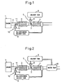
- FIG. 1 is an overall view of an exhaust purification device
- FIG. 2 is an overall view showing another embodiment, of an exhaust purification device
- FIG. 3 is an overall view of an exhaust purification device
- FIG. 4 is a view showing an NO x adsorption amount
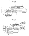
- FIG. 5 is an overall view showing another embodiment of an exhaust purification device
- FIG. 6 is an overall view showing still another embodiment of an exhaust purification device.
- 1 indicates a gasoline engine or diesel engine
- 2 indicates an exhaust passage of the engine 1
- 3 indicates a catalyst 3 able to purify the NO x and arranged in the exhaust passage 2.
- the catalyst 3 any of a three-way catalyst, an NO x purification catalyst purifying NO x in the exhaust gas in the presence of a hydrocarbon, or an NO x storage-reduction type three-way catalyst absorbing NO x in the exhaust gas may be used.
- an NO x adsorbent 4 for adsorbing the NO x in the exhaust gas is arranged.
- the NO x adsorbent 4 comprises one of alumina Al 2 O 3 , ceria CeO 2 , zirconia ZrO 2 , titania TiO 2 , and zeolite. At least one precious metal selected from platinum Pt, palladium Pd, rhodium Rh, and gold Au is carried on the NO x adsorbent 4.
- an NO x removal solvent supply device 5 supplying an NO x removal solvent for dissolving the NO x adsorbed on the NO x adsorbent 4 and a solvent tank 6 for storing the NO x removal solvent are provided.
- the NO x removal solvent supply device 5 is provided with an injector 7 for spraying the NO x removal solvent stored in the solvent tank 6 in the exhaust passage 2 upstream of the NO x adsorbent 4 and a fuel pump 8 for pumping this NO x removal solvent to the injector 7.
- the solvent in the solvent tank 6 becomes low, the solvent is supplied in the solvent tank 6 from the outside.
- an NO x -containing solvent tank 9 for storing an NO x -containing solvent containing NO x removed from the NO x adsorbent 4 by dissolution and an NO x -containing solvent supply device 10 for supplying this NO x -containing solvent in the exhaust passage 2 upstream of the catalyst 3 are provided.
- the NO x -containing solvent supply device 10 is provided with an injector 11 for spraying the NO x -containing solvent stored in the NO x -containing solvent tank 9 into the exhaust passage 2 and a feed pump 12 for pumping this NO x -containing solvent to the injector 11.
- the air-fuel ratio in the combustion chamber of the engine 1 is made the stoichiometric air-fuel ratio or lean.
- the air-fuel ratio in the combustion chamber can be made lean for almost all of the operation period from start of the engine to when the engine is stopped.
- the air-fuel ratio in the combustion chamber is made lean, the oxygen becomes in excess, so unburned HC and CO are not generated so much, but a large amount of NO x is generated.
- the catalyst 3 does not have the ability to purify NO x until the catalyst 3 becomes activated. Accordingly, in the period from when the engine operation is started until the catalyst 3 becomes activated, the large amount of NO x contained in the exhaust gas passes straight through the catalyst 3 without being purified in the catalyst 3.
- NO x which passes straight through the catalyst 3, that is, NO x discharged from the engine 1 is adsorbed on the NO x adsorbent 4. Accordingly, during that time, the discharge of NO x into the air is prevented.
- the catalyst 3 when the catalyst 3 is activated, the NO x in the exhaust gas is purified in the catalyst 3. Accordingly, in this case as well, the discharge of NO x into the air is prevented.
- NO x adsorbed at the NO x adsorbent 4 is removed by dissolution by supplying the NO x removal solvent from the injector 7. That is, specifically speaking, in an embodiment according to the present invention, immediately before the engine stops and immediately after the engine stops, the NO x removal solvent stored in the solvent tank 6 is sprayed from the injector 7 toward the NO x adsorbent 4. By doing so, the NO x adsorbed at the NO x adsorbent 4 is dissolved in the NO x removal solvent and removed from the NO x adsorbent 4. The NO x -containing solvent containing NO x removed from the NO x adsorbent 4 by dissolution is sent to and stored in the NO x -containing solvent tank 9.
- the NO x -containing solvent stored in the NO x -containing solvent tank 9 is supplied from the NO x -containing solvent supply device 10 into the exhaust passage 2.
- the NO x in the NO x -containing solvent supplied at this time is purified in the catalyst 3. Specifically, when the catalyst 3 is activated or sometime after the catalyst 3 is activated, the NO x -containing solvent in the NO x -containing solvent tank 9 is sprayed by the feed pump 12 from the injector 11 into the exhaust passage 2 over a predetermined period. While the NO x -containing solvent is being sprayed, the air-fuel ratio in the combustion chamber is made slightly rich.
- the aforementioned NO x purification catalyst purifying the NO x in the exhaust gas in the presence of a hydrocarbon or the NO x storage-reduction type three-way catalyst absorbing the NO x in the exhaust gas are used.
- this NO x purification catalyst 3 for example, is comprised of Cu zeolite and performs an NO x reduction effect under a lean air-fuel ratio of the exhaust gas.
- the NO x storage-reduction type three-way catalyst 3 for example, carries an NO x absorbent comprising an alkali metal or alkali earth metal.
- the NO x in the exhaust gas is absorbed by the NO x absorbent.
- the air-fuel ratio of the exhaust gas flowing into the NO x storage-reduction type three-way catalyst 3 is made temporarily rich, the NO x absorbed in the NO x absorbent is released from the NO x absorbent and reduced.
- a three-way catalyst is used as the catalyst 3.
- the three-way catalyst 3 and the air-fuel ratio in the combustion chamber is maintained at substantially the stoichiometric air-fuel ratio, not only is the NO x in the exhaust gas removed, but also the unburned HC and CO are removed.
- FIG. 2 shows a different embodiment using water as the NO x removal solvent and therefore not requiring refill of the solvent.
- a water trap 13 for trapping moisture contained in the exhaust gas is arranged in the exhaust passage 2 downstream of the NO x adsorbent 4. Water trapped in the water trap 13 is sent into the solvent tank 6.
- the water stored in the solvent tank 6, that is, the water trapped in the water trap 13 is used.
- the water used for removing the NO x from the NO x adsorbent 4 by dissolution in this way is trapped from inside the exhaust gas, so water does not have to be particularly refilled from the outside.
- FIG. 3 shows a case where aqueous hydrogen peroxide is used as the NO x removal solvent.
- the solvent tank 6 shown in FIG. 1 stores the aqueous hydrogen peroxide inside it, so this solvent tank 6 is called an "aqueous hydrogen peroxide tank 6" in the case shown in FIG. 3 .
- the NO x -containing solvent tank 9 shown in FIG. 1 stores the NO x -containing aqueous solution containing NO x removed from the NO x adsorbent 4 by dissolution, so this NO x -containing solvent tank 9 is called an "NO x -containing aqueous solution tank 9" in the case shown in FIG. 3 .
- NO x which passes through the catalyst 3, that is, NO x discharged from the engine 1 is adsorbed at the NO x adsorbent 4.
- the NO x adsorbent 4 adsorbs the majority of the NO x in the form of NO 2 - and a portion in the form of NO.
- the aqueous hydrogen peroxide is supplied to the adsorbed NO x from the injector 7, the following reaction occurs.
- the adsorbed NO x is dissolved in the water in the form of nitric acid ions NO 3 - and removed from the NO x adsorbent 4.
- FIG. 4 shows the results of an experiment of the NO x adsorption amount when using a 35 cc test piece of the NO x adsorbent 4.
- X indicates an NO x adsorption amount when NO x is first adsorbed on the test piece
- Y indicates an NO x adsorption amount after 150 cc of aqueous hydrogen peroxide of the concentration shown in the abssisa is run over the test piece.
- the NO x adsorption amount after NO x had been removed by dissolution once from the NO x adsorbent 4 increases the higher the concentration of aqueous hydrogen peroxide.
- the concentration of aqueous hydrogen peroxide the more preferable.
- the aqueous hydrogen peroxide will become a poison when it becomes a concentration of 6% or more, it can be said to be preferable for the concentration of the aqueous hydrogen peroxide to be used to be made as high as possible within 6%.
- the NO x adsorbed on the NO x adsorbent 4 is removed by dissolution by supplying aqueous hydrogen peroxide from the injector 7. That is, specifically speaking, in an embodiment according to the present invention, immediately before the engine is stopped and immediately after the engine is stopped, aqueous hydrogen peroxide stored in the aqueous hydrogen peroxide tank 6 is sprayed from the injector 7 toward the NO x adsorbent 4. By doing this, the NO x adsorbed on the NO x adsorbent 4 dissolves in water in the form of NO 3 - and is removed from the NO x adsorbent 4. The NO x removed by dissolution from the NO x adsorbent 4, that is, the NO x -containing aqueous solution containing NO 3 - , is sent to and stored in the NO x -containing aqueous solution tank 9.
- the NO x -containing aqueous solution stored in the NO x -containing aqueous solution tank 9 is supplied from the NO x -containing aqueous solution supply device 10 into the exhaust passage 2.
- the NO x in the NO x -containing aqueous solution supplied at this time is purified in the catalyst 3.
- the NO x -containing aqueous solution in the NO x -containing aqueous solution tank 9 is sprayed by the feed pump 12 from the injector 11 into the exhaust passage 2 over a predetermined period.
- the air-fuel ratio in the combustion chamber is made slightly rich.
- the air-fuel ratio in the combustion chamber is rich, large amounts of unburned HC and CO are contained in the exhaust gas.
- the NO x in the NO x -containing solvent sprayed from the injector 11 is reduced by these unburned HC and CO on the catalyst 3. That is, the NO x contained in the spray is purified in the catalyst 3.
- FIG. 5 and FIG. 6 respectively show different embodiments not requiring refilling aqueous hydrogen peroxide.
- a water trap 13 for trapping moisture contained in the exhaust gas is arranged in the exhaust passage 2 downstream of the NO x adsorbent 4.
- Aqueous hydrogen peroxide is produced using water trapped in the water trap 13.
- an aqueous hydrogen peroxide generator 15 for converting water trapped in the water trap 13 to aqueous hydrogen peroxide is provided in the water guide passage 14 connecting the water trap 13 and the aqueous hydrogen peroxide tank 6.
- the aqueous hydrogen peroxide produced in the aqueous hydrogen peroxide generator 15 is supplied into the aqueous hydrogen peroxide tank 6. Accordingly, in this embodiment, it is not necessary in particular to refill the aqueous hydrogen peroxide from the outside.
- the aqueous hydrogen peroxide generator shown in FIG. 5 comes in various types. Giving one example, an aqueous hydrogen peroxide generator provided with an anode and cathode arranged facing each other in the water and electrolytically reducing the oxygen at the cathode so as to produce aqueous hydrogen peroxide may be used.
- the water trapped in the water trap 13 is supplied through the water guide passage 14 into the aqueous hydrogen peroxide tank 6, and an ozone feed part 16 for supplying ozone into the aqueous hydrogen peroxide tank 6 is provided.
- ozone is supplied into the aqueous hydrogen peroxide, water is changed into aqueous hydrogen peroxide and the aqueous hydrogen peroxide is made to contain ozone.
- the degree of solubility of the NO x in water increases, therefore the NO x adsorbed at the NO x adsorbent 4 may be dissolved further easily.
- an ozonator is used to generate ozone from the oxygen in the air. Accordingly, in the embodiment shown in FIG. 6 , it is not necessary to refill aqueous hydrogen peroxide and ozone from the outside.
- an aqueous solution of sodium hydroxide or an alkaline aqueous solution such as ammonia water may be used as an NO x removal solvent.
Landscapes
- Engineering & Computer Science (AREA)
- Chemical & Material Sciences (AREA)
- Combustion & Propulsion (AREA)
- Chemical Kinetics & Catalysis (AREA)
- General Engineering & Computer Science (AREA)
- Mechanical Engineering (AREA)
- Health & Medical Sciences (AREA)
- Materials Engineering (AREA)
- Biomedical Technology (AREA)
- Environmental & Geological Engineering (AREA)
- Analytical Chemistry (AREA)
- General Chemical & Material Sciences (AREA)
- Oil, Petroleum & Natural Gas (AREA)
- Toxicology (AREA)
- Exhaust Gas After Treatment (AREA)
- Electrical Control Of Air Or Fuel Supplied To Internal-Combustion Engine (AREA)
Description
- The present invention relates to an exhaust purification device of an internal combustion engine.
- Known in the art is an exhaust gas purification device designed to remove the NOx by spraying exhaust gas discharged from the engine into a bubbling tank filled with water to dissolve the NOx in the water in the bubbling tank, supplying the water dissolving the NOx into a neutralizing tank provided with a large number of electrode plates to convert the NOx contained in the water to a soluble substance by electrolytic action, and discharging the water (see Japanese Patent Publication (A) No.
2003-30171d - However, in the above mentioned exhaust gas purification device, the electrode plates are consumables. Accordingly, there is a problem in that the electrode plates must be replaced often.
- Document D1 (
JP 2006 009761 A - An object of the present invention is to provide an exhaust purification device of an internal combustion engine capable of removing NOx in the exhaust gas from the time of engine startup without using consumables requiring frequent replacement.
- According to the present invention, these is provided an exhaust purification device of an internal combustion engine, wherein a catalyst able to purify NOx is arranged in an engine exhaust passage, an NOx adsorbent adsorbing NOx in exhaust gas is arranged in the engine exhaust passage downstream of the catalyst, an NOx removal solvent supply device supplying an NOx removal solvent for removing by dissolution NOx adsorbed by the NOx adsorbent is provided, an NOx-containing solvent supply device supplying an NOx-containing solvent containing the NOx removed by dissolution from the NOx adsorbent into the engine exhaust passage upstream of the catalyst is provided, NOx discharged from the engine is adsorbed by the NOx adsorbent after the engine starts up until the catalyst is activated, the NOx-containing solvent is supplied from the NOx-containing solvent supply device into the engine exhaust passage when the catalyst is activated, and NOx in the NOx-containing solvent supplied at this time is purified in the catalyst.
-
FIG. 1 is an overall view of an exhaust purification device,FIG. 2 is an overall view showing another embodiment, of an exhaust purification device,FIG. 3 is an overall view of an exhaust purification device,FIG. 4 is a view showing an NOx adsorption amount,FIG. 5 is an overall view showing another embodiment of an exhaust purification device, andFIG. 6 is an overall view showing still another embodiment of an exhaust purification device. - Referring to
FIG. 1, 1 indicates a gasoline engine or diesel engine, 2 indicates an exhaust passage of theengine catalyst 3 able to purify the NOx and arranged in theexhaust passage 2. As thecatalyst 3, any of a three-way catalyst, an NOx purification catalyst purifying NOx in the exhaust gas in the presence of a hydrocarbon, or an NOx storage-reduction type three-way catalyst absorbing NOx in the exhaust gas may be used. - In the
exhaust passage 2 downstream of thecatalyst 3, an NOx adsorbent 4 for adsorbing the NOx in the exhaust gas is arranged. In an embodiment of the present invention, the NOx adsorbent 4 comprises one of alumina Al2O3, ceria CeO2, zirconia ZrO2, titania TiO2, and zeolite. At least one precious metal selected from platinum Pt, palladium Pd, rhodium Rh, and gold Au is carried on the NOx adsorbent 4. - In the embodiment shown in
FIG. 1 , an NOx removalsolvent supply device 5 supplying an NOx removal solvent for dissolving the NOx adsorbed on the NOx adsorbent 4 and asolvent tank 6 for storing the NOx removal solvent are provided. The NOx removalsolvent supply device 5 is provided with aninjector 7 for spraying the NOx removal solvent stored in thesolvent tank 6 in theexhaust passage 2 upstream of the NOx adsorbent 4 and afuel pump 8 for pumping this NOx removal solvent to theinjector 7. In the embodiment shown inFIG. 1 , if the solvent in thesolvent tank 6 becomes low, the solvent is supplied in thesolvent tank 6 from the outside. - On the other hand, in the embodiment shown in
FIG. 1 , an NOx-containingsolvent tank 9 for storing an NOx-containing solvent containing NOx removed from the NOx adsorbent 4 by dissolution and an NOx-containingsolvent supply device 10 for supplying this NOx-containing solvent in theexhaust passage 2 upstream of thecatalyst 3 are provided. The NOx-containingsolvent supply device 10 is provided with aninjector 11 for spraying the NOx-containing solvent stored in the NOx-containingsolvent tank 9 into theexhaust passage 2 and afeed pump 12 for pumping this NOx-containing solvent to theinjector 11. - In an embodiment according to the present invention, at the time of engine startup and in the interval after engine startup to at least when the
catalyst 3 is activated, the air-fuel ratio in the combustion chamber of theengine 1 is made the stoichiometric air-fuel ratio or lean. Of course, in this case, the air-fuel ratio in the combustion chamber can be made lean for almost all of the operation period from start of the engine to when the engine is stopped. When the air-fuel ratio in the combustion chamber is made lean, the oxygen becomes in excess, so unburned HC and CO are not generated so much, but a large amount of NOx is generated. Accordingly, in the period from when the engine operation is started to when thecatalyst 3 becomes activated, if the air-fuel ratio in the combustion chamber is made lean, a large amount of NOx is discharged into theexhaust passage 2. On the other hand, thecatalyst 3 does not have the ability to purify NOx until thecatalyst 3 becomes activated. Accordingly, in the period from when the engine operation is started until thecatalyst 3 becomes activated, the large amount of NOx contained in the exhaust gas passes straight through thecatalyst 3 without being purified in thecatalyst 3. - The same is true when maintaining the air-fuel ratio in the combustion chamber at about the stoichiometric air-fuel ratio. That is, in this case, when the air-fuel ratio in the combustion chamber becomes even slightly lean, a large amount of NOx is generated. Accordingly, in the period from when the engine operation is started until the
catalyst 3 becomes activated, even if the air-fuel ratio in the combustion chamber is maintained at about the stoichiometric air-fuel ratio, a large amount of NOx is discharged into theexhaust passage 2. At this time, as explained above, thecatalyst 3 does not have the ability to purify NOx. Accordingly, in this case as well, in the period from when the engine operation is started until thecatalyst 3 becomes activated, the large amount of NOx contained in the exhaust gas passes straight through thecatalyst 3 without being purified in thecatalyst 3. - In the present invention, in the period from when the engine operation is started until the
catalyst 3 becomes activated, NOx which passes straight through thecatalyst 3, that is, NOx discharged from theengine 1, is adsorbed on the NOx adsorbent 4. Accordingly, during that time, the discharge of NOx into the air is prevented. On the other hand, when thecatalyst 3 is activated, the NOx in the exhaust gas is purified in thecatalyst 3. Accordingly, in this case as well, the discharge of NOx into the air is prevented. - On the other hand, NOx adsorbed at the NOx adsorbent 4 is removed by dissolution by supplying the NOx removal solvent from the
injector 7. That is, specifically speaking, in an embodiment according to the present invention, immediately before the engine stops and immediately after the engine stops, the NOx removal solvent stored in thesolvent tank 6 is sprayed from theinjector 7 toward the NOx adsorbent 4. By doing so, the NOx adsorbed at the NOx adsorbent 4 is dissolved in the NOx removal solvent and removed from the NOx adsorbent 4. The NOx-containing solvent containing NOx removed from the NOx adsorbent 4 by dissolution is sent to and stored in the NOx-containingsolvent tank 9. - When the engine is operated next and the
catalyst 3 is activated, the NOx-containing solvent stored in the NOx-containingsolvent tank 9 is supplied from the NOx-containingsolvent supply device 10 into theexhaust passage 2. The NOx in the NOx-containing solvent supplied at this time is purified in thecatalyst 3. Specifically, when thecatalyst 3 is activated or sometime after thecatalyst 3 is activated, the NOx-containing solvent in the NOx-containingsolvent tank 9 is sprayed by thefeed pump 12 from theinjector 11 into theexhaust passage 2 over a predetermined period. While the NOx-containing solvent is being sprayed, the air-fuel ratio in the combustion chamber is made slightly rich. When the air-fuel ratio in the combustion chamber is made rich, a large amount of unburned HC and CO are contained in the exhaust gas. The NOx in the NOx-containing solvent sprayed from theinjector 11 is reduced by these unburned HC and CO in thecatalyst 3. That is, the NOx contained in the spray is purified in thecatalyst 3. - Except when the NOx-containing solvent is being sprayed from the
injector 11, when the air-fuel ratio in the combustion chamber is made lean even after thecatalyst 3 is activated, as thecatalyst 3, the aforementioned NOx purification catalyst purifying the NOx in the exhaust gas in the presence of a hydrocarbon or the NOx storage-reduction type three-way catalyst absorbing the NOx in the exhaust gas are used. Note that this NOx purification catalyst 3, for example, is comprised of Cu zeolite and performs an NOx reduction effect under a lean air-fuel ratio of the exhaust gas. On the other hand, the NOx storage-reduction type three-way catalyst 3, for example, carries an NOx absorbent comprising an alkali metal or alkali earth metal. When the air-fuel ratio of the exhaust gas flowing into the NOx storage-reduction type three-way catalyst 3 is lean, the NOx in the exhaust gas is absorbed by the NOx absorbent. In this case, when the air-fuel ratio of the exhaust gas flowing into the NOx storage-reduction type three-way catalyst 3 is made temporarily rich, the NOx absorbed in the NOx absorbent is released from the NOx absorbent and reduced. - On the other hand, except when the NOx-containing solvent is being sprayed from the
injector 11, when the air-fuel ratio in the combustion chamber is maintained at about the stoichiometric air-fuel ratio after thecatalyst 3 is activated, a three-way catalyst is used as thecatalyst 3. When using the three-way catalyst 3 and the air-fuel ratio in the combustion chamber is maintained at substantially the stoichiometric air-fuel ratio, not only is the NOx in the exhaust gas removed, but also the unburned HC and CO are removed. - As explained above, in the embodiment shown in
FIG. 1 , when the solvent in thesolvent tank 6 becomes low, the solvent must be refilled.FIG. 2 shows a different embodiment using water as the NOx removal solvent and therefore not requiring refill of the solvent. - Referring to
FIG. 2 , in this embodiment, awater trap 13 for trapping moisture contained in the exhaust gas is arranged in theexhaust passage 2 downstream of the NOx adsorbent 4. Water trapped in thewater trap 13 is sent into thesolvent tank 6. In this embodiment, when removing NOx adsorbed from the NOx adsorbent 4 by dissolution, the water stored in thesolvent tank 6, that is, the water trapped in thewater trap 13, is used. The water used for removing the NOx from the NOx adsorbent 4 by dissolution in this way is trapped from inside the exhaust gas, so water does not have to be particularly refilled from the outside. -
FIG. 3 shows a case where aqueous hydrogen peroxide is used as the NOx removal solvent. In this case, thesolvent tank 6 shown inFIG. 1 stores the aqueous hydrogen peroxide inside it, so thissolvent tank 6 is called an "aqueoushydrogen peroxide tank 6" in the case shown inFIG. 3 . Further, the NOx-containingsolvent tank 9 shown inFIG. 1 stores the NOx-containing aqueous solution containing NOx removed from the NOx adsorbent 4 by dissolution, so this NOx-containingsolvent tank 9 is called an "NOx-containingaqueous solution tank 9" in the case shown inFIG. 3 . Note that, in this embodiment as well, in the same way as in the embodiment shown inFIG. 1 , when the aqueous hydrogen peroxide in the aqueoushydrogen peroxide tank 6 becomes low, the aqueous hydrogen peroxide is refilled from the outside into the aqueoushydrogen peroxide tank 6. - In this embodiment as well, in the period from when the engine operation is started until the
catalyst 3 becomes activated, NOx which passes through thecatalyst 3, that is, NOx discharged from theengine 1, is adsorbed at the NOx adsorbent 4. At this time, the NOx adsorbent 4 adsorbs the majority of the NOx in the form of NO2 - and a portion in the form of NO. When the aqueous hydrogen peroxide is supplied to the adsorbed NOx from theinjector 7, the following reaction occurs. As a result, the adsorbed NOx is dissolved in the water in the form of nitric acid ions NO3 - and removed from the NOx adsorbent 4.
NO2 -+H2O2→NO3 -+H2O
NO+2H2O2→NO3 -+2H2O
- Here, the results of an experiment relating to a concentration of aqueous hydrogen peroxide suitable for removing NOx from the NOx adsorbent 4 by dissolution will be explained. In this experiment, as the NOx adsorbent 4, an NOx adsorbent 4 obtained by first wash-coating alumina Al2O3 (200 g/l) on a honeycomb structure comprising cordierite, then firing this at 500°C for 2 hours, then impregnating 2 (g/l) of platinum Pt by using a dinitro diammine Pt nitrate solution (4%), then firing this at 500°C for 2 hours is used.
-
FIG. 4 shows the results of an experiment of the NOx adsorption amount when using a 35 cc test piece of the NOx adsorbent 4. Note that, inFIG. 4 , X indicates an NOx adsorption amount when NOx is first adsorbed on the test piece, and Y indicates an NOx adsorption amount after 150 cc of aqueous hydrogen peroxide of the concentration shown in the abssisa is run over the test piece. As shown in Y ofFIG. 4 , the NOx adsorption amount after NOx had been removed by dissolution once from the NOx adsorbent 4 increases the higher the concentration of aqueous hydrogen peroxide. Accordingly, the higher the concentration of aqueous hydrogen peroxide, the more preferable. However, the aqueous hydrogen peroxide will become a poison when it becomes a concentration of 6% or more, it can be said to be preferable for the concentration of the aqueous hydrogen peroxide to be used to be made as high as possible within 6%. - As explained above, the NOx adsorbed on the NOx adsorbent 4 is removed by dissolution by supplying aqueous hydrogen peroxide from the
injector 7. That is, specifically speaking, in an embodiment according to the present invention, immediately before the engine is stopped and immediately after the engine is stopped, aqueous hydrogen peroxide stored in the aqueoushydrogen peroxide tank 6 is sprayed from theinjector 7 toward the NOx adsorbent 4. By doing this, the NOx adsorbed on the NOx adsorbent 4 dissolves in water in the form of NO3 - and is removed from the NOx adsorbent 4. The NOx removed by dissolution from the NOx adsorbent 4, that is, the NOx-containing aqueous solution containing NO3 -, is sent to and stored in the NOx-containingaqueous solution tank 9. - When the engine is operated next and the
catalyst 3 is activated, the NOx-containing aqueous solution stored in the NOx-containingaqueous solution tank 9 is supplied from the NOx-containing aqueoussolution supply device 10 into theexhaust passage 2. The NOx in the NOx-containing aqueous solution supplied at this time is purified in thecatalyst 3. Specifically speaking, when thecatalyst 3 is activated or sometime after thecatalyst 3 becomes activated, the NOx-containing aqueous solution in the NOx-containingaqueous solution tank 9 is sprayed by thefeed pump 12 from theinjector 11 into theexhaust passage 2 over a predetermined period. In the period when the NOx-containing solvent is sprayed, the air-fuel ratio in the combustion chamber is made slightly rich. When the air-fuel ratio in the combustion chamber is rich, large amounts of unburned HC and CO are contained in the exhaust gas. The NOx in the NOx-containing solvent sprayed from theinjector 11 is reduced by these unburned HC and CO on thecatalyst 3. That is, the NOx contained in the spray is purified in thecatalyst 3. - As explained above, in the embodiment shown in
FIG. 3 , when the aqueous hydrogen peroxide in the aqueoushydrogen peroxide tank 6 becomes low, the aqueous hydrogen peroxide must be refilled.FIG. 5 and FIG. 6 respectively show different embodiments not requiring refilling aqueous hydrogen peroxide. - Referring to
FIG. 5 , in this embodiment, awater trap 13 for trapping moisture contained in the exhaust gas is arranged in theexhaust passage 2 downstream of the NOx adsorbent 4. Aqueous hydrogen peroxide is produced using water trapped in thewater trap 13. Specifically speaking, in the embodiment shown inFIG. 5 , in thewater guide passage 14 connecting thewater trap 13 and the aqueoushydrogen peroxide tank 6, an aqueoushydrogen peroxide generator 15 for converting water trapped in thewater trap 13 to aqueous hydrogen peroxide is provided. The aqueous hydrogen peroxide produced in the aqueoushydrogen peroxide generator 15 is supplied into the aqueoushydrogen peroxide tank 6. Accordingly, in this embodiment, it is not necessary in particular to refill the aqueous hydrogen peroxide from the outside. - The aqueous hydrogen peroxide generator shown in
FIG. 5 comes in various types. Giving one example, an aqueous hydrogen peroxide generator provided with an anode and cathode arranged facing each other in the water and electrolytically reducing the oxygen at the cathode so as to produce aqueous hydrogen peroxide may be used. - On the other hand, in the embodiment shown in
FIG. 6 , the water trapped in thewater trap 13 is supplied through thewater guide passage 14 into the aqueoushydrogen peroxide tank 6, and anozone feed part 16 for supplying ozone into the aqueoushydrogen peroxide tank 6 is provided. When ozone is supplied into the aqueous hydrogen peroxide, water is changed into aqueous hydrogen peroxide and the aqueous hydrogen peroxide is made to contain ozone. When ozone is contained in the water, the degree of solubility of the NOx in water increases, therefore the NOx adsorbed at the NOx adsorbent 4 may be dissolved further easily. - In the
ozone feed part 16, for example, an ozonator is used to generate ozone from the oxygen in the air. Accordingly, in the embodiment shown inFIG. 6 , it is not necessary to refill aqueous hydrogen peroxide and ozone from the outside. - Note that, an aqueous solution of sodium hydroxide or an alkaline aqueous solution such as ammonia water may be used as an NOx removal solvent.
-
- 1 engine
- 2 exhaust passage
- 3 catalyst
- 4 NOx adsorbent
- 5 NOx removal solvent supply device, aqueous hydrogen peroxide supply device
- 6 solvent tank, aqueous hydrogen peroxide tank
- 7, 11 injector
- 8, 12 fuel pump
- 9 NOx-containing solvent tank, NOx-containing aqueous solution tank
- 10 NOx-containing solvent supply device, NOx-containing aqueous solution supply device
Claims (15)
- An exhaust purification device of an internal combustion engine, wherein a catalyst (3) able to purify NOx is arranged in an engine exhaust passage (2), an NOx adsorbent (4) adsorbing NOx in exhaust gas is arranged in the engine exhaust passage(2) downstream of the catalyst (3), an NOx removal solvent supply device (5) supplying an NOx removal solvent for removing by dissolution NOx adsorbed by the NOx adsorbent (4) is provided, characterized by an NOx-containing solvent supply device (10) supplying an NOx-containing solvent containing the NOx removed by dissolution from the NOx adsorbent (4) into the engine exhaust passage (2) upstream of said catalyst (3) is provided, NOx discharged from the engine (1) is adsorbed by said NOx adsorbent (4) after the engine (1) starts up until said catalyst (3) is activated, the NOx-containing solvent is supplied from the NOx-containing solvent supply device (10) into the engine exhaust passage (2) when said catalyst (3) is activated, and NOx in the NOx-containing solvent supplied at this time is purified in said catalyst (3).
- An exhaust purification device of an internal combustion engine as claimed in claim 1, wherein when NOx-containing solvent is supplied into the engine exhaust passage (2), an air-fuel ratio is made rich.
- An exhaust purification device of an internal combustion engine as claimed in claim 1, wherein an air-fuel ratio is made the stoichiometric air-fuel ratio or lean in the interval after engine startup to at least when said catalyst (3) is activated.
- An exhaust purification device of an internal combustion engine as claimed in claim 1, wherein immediately before the engine (1) is stopped or immediately after the engine (1) is stopped, the NOx removal solvent is supplied to the NOx adsorbent (4).
- An exhaust purification device of an internal combustion engine as claimed in claim 1, wherein said catalyst (3) comprises a three-way catalyst (3), an NOx purification catalyst (3) purifying NOx in the exhaust gas in the presence of hydrocarbons, or an NOx storage-reduction type three-way catalyst (3) absorbing NOx in the exhaust gas.
- An exhaust purification device of an internal combustion engine as claimed in claim 1, wherein said NOx adsorbent (4) comprises one of alumina, ceria, zirconia, titania, and zeolite, and one precious metal selected from platinum, palladium, rhodium, and gold is carried on the NOx adsorbent (4).
- An exhaust purification device of an internal combustion engine as claimed in claim 1, wherein an NOx-containing solvent tank (9) for storing an NOx-containing solvent is provided and said NOx-containing solvent supply device (10) is provided with an injector (11) for spraying the NOx-containing solvent stored in the NOx-containing solvent tank (9) into the engine exhaust passage (2).
- An exhaust purification device of an internal combustion engine as claimed in claim 1, wherein a solvent tank (6) for storing the NOx removal solvent is provided, and said NOx removal solvent supply device (5) is provided with an injector (7) for spraying the NOx removal solvent stored in the solvent tank (6) in the engine exhaust passage (2) upstream of the NOx adsorbent (4).
- An exhaust purification device of an internal combustion engine as claimed in claim 1, wherein said NOx removal solvent is comprised of water.
- An exhaust purification device of an internal combustion engine as claimed in claim 9, wherein a water trap (13) for trapping moisture contained in the exhaust gas is arranged in the engine exhaust passage (2) downstream of said NOx adsorbent (4), and water trapped in said water trap (13) is used as said NOx removal solvent.
- An exhaust purification device of an internal combustion engine as claimed in claim 1, wherein said NOx removal solvent is comprised of aqueous hydrogen peroxide.
- An exhaust purification device of an internal combustion engine as claimed in claim 11, wherein a water trap (13) for trapping moisture contained in the exhaust gas is arranged in the engine exhaust passage (2) downstream of said NOx adsorbent (4), and aqueous hydrogen peroxide is produced by using water trapped in said water trap (13).
- An exhaust purification device of an internal combustion engine as claimed in claim 12, wherein an aqueous hydrogen peroxide generator (15) for converting water trapped in said water trap (13) into aqueous hydrogen peroxide is provided, the aqueous hydrogen peroxide produced in the aqueous hydrogen peroxide generator (15) is supplied into an aqueous hydrogen peroxide tank (6), and the aqueous hydrogen peroxide stored in the aqueous hydrogen peroxide tank (6) is used as the NOx removal solvent.
- An exhaust purification device of an internal combustion engine as claimed in claim 12, wherein water trapped in said water trap (13) is supplied into said aqueous hydrogen peroxide tank (6), and said aqueous hydrogen peroxide tank (6) is supplied with ozone to convert the water to aqueous hydrogen peroxide and make the aqueous hydrogen peroxide in the aqueous hydrogen peroxide tank (6) contain ozone.
- An exhaust purification device of an internal combustion engine as claimed in claim 14, wherein said ozone is generated using oxygen in the air.
Applications Claiming Priority (3)
| Application Number | Priority Date | Filing Date | Title |
|---|---|---|---|
| JP2006098013 | 2006-03-31 | ||
| JP2006098119 | 2006-03-31 | ||
| PCT/JP2007/056748 WO2007114201A1 (en) | 2006-03-31 | 2007-03-22 | Exhaust purification apparatus for internal combustion engine |
Publications (3)
| Publication Number | Publication Date |
|---|---|
| EP2003298A1 EP2003298A1 (en) | 2008-12-17 |
| EP2003298A4 EP2003298A4 (en) | 2010-01-27 |
| EP2003298B1 true EP2003298B1 (en) | 2011-02-16 |
Family
ID=38563470
Family Applications (1)
| Application Number | Title | Priority Date | Filing Date |
|---|---|---|---|
| EP07740186A Not-in-force EP2003298B1 (en) | 2006-03-31 | 2007-03-22 | Exhaust purification apparatus for internal combustion engine |
Country Status (5)
| Country | Link |
|---|---|
| US (1) | US8042327B2 (en) |
| EP (1) | EP2003298B1 (en) |
| JP (1) | JP4697304B2 (en) |
| DE (1) | DE602007012527D1 (en) |
| WO (1) | WO2007114201A1 (en) |
Families Citing this family (3)
| Publication number | Priority date | Publication date | Assignee | Title |
|---|---|---|---|---|
| JP4780230B2 (en) * | 2009-06-05 | 2011-09-28 | トヨタ自動車株式会社 | Exhaust gas purification device for internal combustion engine |
| GB2510171B (en) | 2013-01-28 | 2015-01-28 | Cool Flame Technologies As | Method and cleaning apparatus for removal of SOx and NOx from exhaust gas |
| JP2018031358A (en) * | 2016-08-26 | 2018-03-01 | トヨタ自動車株式会社 | Exhaust pipe structure |
Family Cites Families (11)
| Publication number | Priority date | Publication date | Assignee | Title |
|---|---|---|---|---|
| JPS4917366A (en) * | 1972-06-10 | 1974-02-15 | ||
| JPH04118021A (en) | 1990-09-07 | 1992-04-20 | Mitsui Eng & Shipbuild Co Ltd | Nox and co2 exhausting quantity reducing device for coordinated energy recovering device |
| DK0548499T3 (en) | 1991-11-02 | 1996-02-05 | Degussa | Process for oxidative purification of exhaust gases containing nitrogen oxides |
| JP2634563B2 (en) | 1994-07-27 | 1997-07-30 | 株式会社三条東和 | Engine exhaust gas purification device |
| JP3347225B2 (en) * | 1994-08-23 | 2002-11-20 | 勲 山本 | NOx reduction device for exhaust gas |
| JPH10266831A (en) | 1997-03-24 | 1998-10-06 | Akira Mizuno | Exhaust gas control system |
| US6171337B1 (en) | 1999-03-31 | 2001-01-09 | Miles A. Galin | Positive power anterior chamber ocular implant |
| JP3560147B2 (en) | 1999-07-02 | 2004-09-02 | 日産自動車株式会社 | Exhaust gas purification system |
| JP2003301714A (en) * | 2002-04-11 | 2003-10-24 | Denso Corp | Exhaust emission control device |
| JP2006009761A (en) * | 2004-06-29 | 2006-01-12 | Denso Corp | Exhaust emission control device |
| EP1625884B1 (en) * | 2004-08-11 | 2011-01-26 | Umicore AG & Co. KG | Device and method of reducing vehicular NOx emissions |
-
2007
- 2007-03-22 EP EP07740186A patent/EP2003298B1/en not_active Not-in-force
- 2007-03-22 WO PCT/JP2007/056748 patent/WO2007114201A1/en not_active Ceased
- 2007-03-22 US US12/295,354 patent/US8042327B2/en not_active Expired - Fee Related
- 2007-03-22 DE DE602007012527T patent/DE602007012527D1/en active Active
- 2007-03-22 JP JP2008508579A patent/JP4697304B2/en not_active Expired - Fee Related
Also Published As
| Publication number | Publication date |
|---|---|
| JPWO2007114201A1 (en) | 2009-08-13 |
| US8042327B2 (en) | 2011-10-25 |
| EP2003298A1 (en) | 2008-12-17 |
| DE602007012527D1 (en) | 2011-03-31 |
| JP4697304B2 (en) | 2011-06-08 |
| US20090272100A1 (en) | 2009-11-05 |
| WO2007114201A1 (en) | 2007-10-11 |
| EP2003298A4 (en) | 2010-01-27 |
Similar Documents
| Publication | Publication Date | Title |
|---|---|---|
| EP2098699B1 (en) | Exhaust gas purifying apparatus for internal combustion engine | |
| EP2003298B1 (en) | Exhaust purification apparatus for internal combustion engine | |
| JP2019203487A (en) | Fuel reforming device and control method therefor | |
| CN101573514A (en) | Exhaust gas purification device for internal combustion engine | |
| JP2010017694A (en) | NOx ABSORBING CATALYST FOR REDUCTION | |
| JP4453700B2 (en) | Exhaust gas purification device for internal combustion engine | |
| RU2385760C2 (en) | Method and device for treatment of exhaust gas | |
| JP5094199B2 (en) | Exhaust gas purification device | |
| JP4626854B2 (en) | Exhaust gas purification device for internal combustion engine | |
| KR101000935B1 (en) | Exhaust purifier of internal combustion engine | |
| JP4525442B2 (en) | Exhaust gas purification device for internal combustion engine | |
| JP4161478B2 (en) | Exhaust gas purification catalyst | |
| JP3560147B2 (en) | Exhaust gas purification system | |
| JP4997967B2 (en) | Exhaust gas purification device for internal combustion engine | |
| JP4877574B2 (en) | Exhaust gas purification device for internal combustion engine | |
| JP4867655B2 (en) | Exhaust gas purification device for internal combustion engine | |
| JP2005211862A (en) | Exhaust purification catalyst | |
| JP4172370B2 (en) | Method for producing exhaust gas purification catalyst | |
| JP2002070538A (en) | NOx purification method | |
| JP2002143647A (en) | Nitrogen oxide purifying element | |
| KR20080101451A (en) | Exhaust gas purifier using plasma reformer | |
| JP2007113497A (en) | Exhaust gas purification device for internal combustion engine | |
| CN120693212A (en) | Catalysts for exhaust gas purification | |
| JP2006037811A (en) | Exhaust gas purification device for internal combustion engine and exhaust gas purification method |
Legal Events
| Date | Code | Title | Description |
|---|---|---|---|
| PUAI | Public reference made under article 153(3) epc to a published international application that has entered the european phase |
Free format text: ORIGINAL CODE: 0009012 |
|
| 17P | Request for examination filed |
Effective date: 20080926 |
|
| AK | Designated contracting states |
Kind code of ref document: A1 Designated state(s): DE FR GB IT |
|
| DAX | Request for extension of the european patent (deleted) | ||
| RBV | Designated contracting states (corrected) |
Designated state(s): DE FR GB IT |
|
| A4 | Supplementary search report drawn up and despatched |
Effective date: 20091229 |
|
| RIC1 | Information provided on ipc code assigned before grant |
Ipc: F01N 3/24 20060101ALI20100311BHEP Ipc: B01D 53/94 20060101ALI20100311BHEP Ipc: F01N 3/08 20060101AFI20100311BHEP Ipc: F02D 43/00 20060101ALI20100311BHEP Ipc: F01N 3/04 20060101ALI20100311BHEP |
|
| GRAP | Despatch of communication of intention to grant a patent |
Free format text: ORIGINAL CODE: EPIDOSNIGR1 |
|
| GRAC | Information related to communication of intention to grant a patent modified |
Free format text: ORIGINAL CODE: EPIDOSCIGR1 |
|
| GRAS | Grant fee paid |
Free format text: ORIGINAL CODE: EPIDOSNIGR3 |
|
| RIN1 | Information on inventor provided before grant (corrected) |
Inventor name: SOBUE, YUICHI Inventor name: INATOMI, YUSAKU Inventor name: TOYOSHIMA, NAGAO Inventor name: MATSUBARA, HIROYUKI |
|
| GRAA | (expected) grant |
Free format text: ORIGINAL CODE: 0009210 |
|
| AK | Designated contracting states |
Kind code of ref document: B1 Designated state(s): DE FR GB IT |
|
| REG | Reference to a national code |
Ref country code: GB Ref legal event code: FG4D |
|
| REF | Corresponds to: |
Ref document number: 602007012527 Country of ref document: DE Date of ref document: 20110331 Kind code of ref document: P |
|
| REG | Reference to a national code |
Ref country code: DE Ref legal event code: R096 Ref document number: 602007012527 Country of ref document: DE Effective date: 20110331 |
|
| PLBE | No opposition filed within time limit |
Free format text: ORIGINAL CODE: 0009261 |
|
| STAA | Information on the status of an ep patent application or granted ep patent |
Free format text: STATUS: NO OPPOSITION FILED WITHIN TIME LIMIT |
|
| 26N | No opposition filed |
Effective date: 20111117 |
|
| REG | Reference to a national code |
Ref country code: DE Ref legal event code: R097 Ref document number: 602007012527 Country of ref document: DE Effective date: 20111117 |
|
| PGFP | Annual fee paid to national office [announced via postgrant information from national office to epo] |
Ref country code: FR Payment date: 20120319 Year of fee payment: 6 |
|
| PGFP | Annual fee paid to national office [announced via postgrant information from national office to epo] |
Ref country code: IT Payment date: 20120317 Year of fee payment: 6 Ref country code: GB Payment date: 20120321 Year of fee payment: 6 |
|
| PGFP | Annual fee paid to national office [announced via postgrant information from national office to epo] |
Ref country code: DE Payment date: 20120411 Year of fee payment: 6 |
|
| REG | Reference to a national code |
Ref country code: GB Ref legal event code: 746 Effective date: 20121219 |
|
| REG | Reference to a national code |
Ref country code: DE Ref legal event code: R084 Ref document number: 602007012527 Country of ref document: DE Effective date: 20121213 |
|
| GBPC | Gb: european patent ceased through non-payment of renewal fee |
Effective date: 20130322 |
|
| REG | Reference to a national code |
Ref country code: FR Ref legal event code: ST Effective date: 20131129 |
|
| REG | Reference to a national code |
Ref country code: DE Ref legal event code: R119 Ref document number: 602007012527 Country of ref document: DE Effective date: 20131001 |
|
| PG25 | Lapsed in a contracting state [announced via postgrant information from national office to epo] |
Ref country code: FR Free format text: LAPSE BECAUSE OF NON-PAYMENT OF DUE FEES Effective date: 20130402 Ref country code: DE Free format text: LAPSE BECAUSE OF NON-PAYMENT OF DUE FEES Effective date: 20131001 Ref country code: GB Free format text: LAPSE BECAUSE OF NON-PAYMENT OF DUE FEES Effective date: 20130322 |
|
| PG25 | Lapsed in a contracting state [announced via postgrant information from national office to epo] |
Ref country code: IT Free format text: LAPSE BECAUSE OF NON-PAYMENT OF DUE FEES Effective date: 20130322 |