EP2003218A1 - Anodised magnesium alloy member, method for producing the same, and transporter comprising the same - Google Patents
Anodised magnesium alloy member, method for producing the same, and transporter comprising the same Download PDFInfo
- Publication number
- EP2003218A1 EP2003218A1 EP20080010621 EP08010621A EP2003218A1 EP 2003218 A1 EP2003218 A1 EP 2003218A1 EP 20080010621 EP20080010621 EP 20080010621 EP 08010621 A EP08010621 A EP 08010621A EP 2003218 A1 EP2003218 A1 EP 2003218A1
- Authority
- EP
- European Patent Office
- Prior art keywords
- anodic oxidation
- magnesium alloy
- main body
- layer
- member main
- Prior art date
- Legal status (The legal status is an assumption and is not a legal conclusion. Google has not performed a legal analysis and makes no representation as to the accuracy of the status listed.)
- Granted
Links
Images




Classifications
-
- C—CHEMISTRY; METALLURGY
- C22—METALLURGY; FERROUS OR NON-FERROUS ALLOYS; TREATMENT OF ALLOYS OR NON-FERROUS METALS
- C22B—PRODUCTION AND REFINING OF METALS; PRETREATMENT OF RAW MATERIALS
- C22B26/00—Obtaining alkali, alkaline earth metals or magnesium
- C22B26/20—Obtaining alkaline earth metals or magnesium
- C22B26/22—Obtaining magnesium
-
- C—CHEMISTRY; METALLURGY
- C22—METALLURGY; FERROUS OR NON-FERROUS ALLOYS; TREATMENT OF ALLOYS OR NON-FERROUS METALS
- C22C—ALLOYS
- C22C23/00—Alloys based on magnesium
- C22C23/02—Alloys based on magnesium with aluminium as the next major constituent
-
- C—CHEMISTRY; METALLURGY
- C25—ELECTROLYTIC OR ELECTROPHORETIC PROCESSES; APPARATUS THEREFOR
- C25D—PROCESSES FOR THE ELECTROLYTIC OR ELECTROPHORETIC PRODUCTION OF COATINGS; ELECTROFORMING; APPARATUS THEREFOR
- C25D11/00—Electrolytic coating by surface reaction, i.e. forming conversion layers
- C25D11/02—Anodisation
- C25D11/30—Anodisation of magnesium or alloys based thereon
-
- Y—GENERAL TAGGING OF NEW TECHNOLOGICAL DEVELOPMENTS; GENERAL TAGGING OF CROSS-SECTIONAL TECHNOLOGIES SPANNING OVER SEVERAL SECTIONS OF THE IPC; TECHNICAL SUBJECTS COVERED BY FORMER USPC CROSS-REFERENCE ART COLLECTIONS [XRACs] AND DIGESTS
- Y10—TECHNICAL SUBJECTS COVERED BY FORMER USPC
- Y10T—TECHNICAL SUBJECTS COVERED BY FORMER US CLASSIFICATION
- Y10T428/00—Stock material or miscellaneous articles
- Y10T428/249921—Web or sheet containing structurally defined element or component
- Y10T428/249953—Composite having voids in a component [e.g., porous, cellular, etc.]
-
- Y—GENERAL TAGGING OF NEW TECHNOLOGICAL DEVELOPMENTS; GENERAL TAGGING OF CROSS-SECTIONAL TECHNOLOGIES SPANNING OVER SEVERAL SECTIONS OF THE IPC; TECHNICAL SUBJECTS COVERED BY FORMER USPC CROSS-REFERENCE ART COLLECTIONS [XRACs] AND DIGESTS
- Y10—TECHNICAL SUBJECTS COVERED BY FORMER USPC
- Y10T—TECHNICAL SUBJECTS COVERED BY FORMER US CLASSIFICATION
- Y10T428/00—Stock material or miscellaneous articles
- Y10T428/26—Web or sheet containing structurally defined element or component, the element or component having a specified physical dimension
- Y10T428/263—Coating layer not in excess of 5 mils thick or equivalent
- Y10T428/264—Up to 3 mils
- Y10T428/265—1 mil or less
Definitions
- the present invention relates to a magnesium alloy member, and in particular to a magnesium alloy member including an anodic oxidation coating.
- the present invention also relates to a method for producing such a magnesium alloy member and a transporter including such a magnesium alloy member.
- alloys of titanium, aluminum and magnesium as materials for members of transporters.
- the weight of the transporters can be significantly reduced because the density of magnesium is about 23% of that of steel.
- magnesium alloys are more likely to be corroded than aluminum alloys in certain environments.
- an anodic oxidation coating is formed on a surface of a magnesium alloy.
- An anodic oxidation coating on an aluminum alloy is known to include a porous layer and a non-porous barrier layer. These layers can be observed by an electron microscope.
- An anodic oxidation coating on a magnesium alloy also includes a porous layer and a barrier layer as disclosed in Japanese Laid-Open Patent Publication No. 2006-291278 .
- This publication describes that the corrosion resistance of magnesium alloys can be improved by reducing an average diameter of micropores in a surface area of the porous layer from that in the conventional art to 100 nm to 25 ⁇ m.
- transporters are mainly used outdoors and therefore members forming the transporters are often exposed to severe environments.
- magnesium alloys are desired to have more improved corrosion resistance.
- magnesium alloy members practically used today are used for domestic electronic appliances, particularly for reducing the weight of small mobile devices.
- the magnesium alloy members for these applications are small interior components and are not required to have such a high corrosion resistance as is required of those used for transporters.
- anodic oxidation coating formed on a magnesium alloy member used for domestic electronic appliances often has a thickness of about 5 ⁇ m to 15 ⁇ m.
- an anodic oxidation coating of such a thickness is formed on a magnesium alloy member for transporters by a conventional technique, a sufficient corrosion resistance is not provided.
- Studies performed by the present inventors have found that a thickness exceeding 15 ⁇ m is required in order to guarantee a sufficient corrosion resistance for a magnesium alloy member used for transporters.
- a porous layer which is mainly formed of magnesium oxide (MgO) or magnesium hydroxide (MgOH), has a convex and concave surface and thus is more brittle than the magnesium alloy which is the starting material.
- MgO magnesium oxide
- MgOH magnesium hydroxide
- preferred embodiments of the present invention provide a method for improving the corrosion resistance of a magnesium alloy without increasing the thickness of the anodic oxidation coating, or even while further reducing the thickness of the anodic oxidation coating than that in the conventional art.
- preferred embodiments of the present invention provide a magnesium alloy member which is superb both in corrosion resistance and fatigue strength, a method for producing the same, and a transporter including such a magnesium alloy member.
- a preferred embodiment of the present invention provides a magnesium alloy member including a member main body formed of a magnesium alloy containing aluminum, and an anodic oxidation coating covering at least a portion of the member main body.
- the anodic oxidation coating includes a porous first layer and a second layer located between the first layer and the member main body and having a higher aluminum content than that of the first layer.
- the ratio of a thickness of the second layer with respect to a thickness of the anodic oxidation coating is preferably 5% or higher and 20% or lower.
- the aluminum content of the second layer is preferably 10% by mass or higher and 20% by mass or lower.
- the thickness of the anodic oxidation coating is preferably 2 ⁇ m or larger and 5 ⁇ m or smaller, and the thickness of the second layer is preferably 200 nm or larger and 500 nm or smaller.
- the first layer preferably has a porosity of 10% or higher; and the second layer preferably has a porosity of lower than 10%.
- the member main body preferably has an aluminum content of 5.5% by mass or higher and 10.0% by mass or lower in an area within 100 ⁇ m from an interface with the anodic oxidation coating.
- the member main body preferably has an average crystalline diameter of 20 ⁇ m or smaller in an area within 100 ⁇ m from an interface with the anodic oxidation coating.
- the anodic oxidation coating preferably has a 10 point average surface roughness of 6.4 Rz or smaller at a surface thereof.
- a magnesium alloy member includes a member main body formed of a magnesium alloy containing aluminum; and an anodic oxidation coating covering at least a portion of the member main body.
- the anodic oxidation coating includes a porous first layer and a second layer located between the first layer and the member main body and having a higher aluminum content than that of the first layer.
- the anodic oxidation coating preferably has a thickness of 2 ⁇ m or larger and 5 ⁇ m or smaller; and the second layer preferably has a thickness of 200 nm or larger and 500 nm or smaller.
- a transporter according to a preferred embodiment of the present invention includes a magnesium alloy member having the above-described structure.
- a method for producing a magnesium alloy member includes the steps of preparing a member main body formed of a magnesium alloy containing aluminum; and forming an anodic oxidation coating on a surface of the member main body.
- the step of forming the anodic oxidation coating is carried out by repeating, a plurality of times, an anodic oxidation step of treating the member main body with anodic oxidation at a prescribed voltage for a prescribed time period; and the anodic oxidation step at each of the second and subsequent times is carried out at a voltage higher than the voltage used for the immediately previous time.
- the anodic oxidation step is carried out at a voltage of preferably 40 V or higher and 150 V or lower.
- the anodic oxidation step at each time is carried out for a time period of preferably 0.001 seconds or longer and 120 seconds or shorter.
- the anodic oxidation step at each of the second and subsequent times is carried out at a voltage higher than the voltage used for the immediately previous time preferalby by 0.5 V or more and 5.0 V or less.
- the anodic oxidation step is repeated at least five times.
- the step of preparing the member main body includes the step of molding the member main body from the magnesium alloy containing aluminum by die-casting.
- the method for producing a magnesium alloy member according to the present invention further includes the step of, before the step of forming the anodic oxidation coating, immersing the member main body in an acidic solution preferably having a concentration of 0.1 mol/1 or higher and 1.0 mol/l or lower and a temperature of 25°C or higher and 40°C or lower for a time period of 60 seconds or longer and 300 seconds or shorter.
- the anodic oxidation coating of the magnesium alloy member according to a preferred embodiment of the present invention includes a porous first layer and a second layer located between the first layer and the member main body and having a higher aluminum content than that of the first layer.
- the ratio of the thickness of the second layer with respect to the thickness of the anodic oxidation coating is preferably 5% or higher and 20% or lower, which is higher than that in the conventional art. Therefore, the thickness of the second layer can be increased without particularly increasing the entire thickness of the anodic oxidation coating. This can further improve the corrosion resistance while preventing the decrease in the fatigue strength. In other words, the magnesium alloy member which is superb both in the fatigue strength and the corrosion resistance is obtained.
- the aluminum content of the second layer preferably is typically 10% by mass or higher and 20% by mass or lower.
- the thickness of the anodic oxidation coating is 2 ⁇ m or larger and 5 ⁇ m or smaller
- a sufficient fatigue strength and a sufficient corrosion resistance are obtained by, for example, forming the second layer with a thickness which is 200 nm or larger and 500 nm or smaller.
- the first layer preferably has a porosity of 10% or higher, whereas the second layer preferably has a porosity of lower than 10%, and more preferably 5% or lower.
- the aluminum content in the vicinity of the surface of the member main body preferably is 5.5% by mass or larger and 10.0% by mass or lower.
- the aluminum content is lower than 5.5% by mass, the formation of spinel (an oxide of magnesium and aluminum as described below) is inhibited and thus the second layer having a sufficient thickness may not be formed.
- the aluminum content is higher than 10.0% by mass, the tenacity of the magnesium alloy is reduced to be inappropriate for being used for the magnesium alloy member.
- each anodic oxidation step the dissolution of the member main body in the vicinity of the surface thereof and the generation of the anodic oxidation coating occur at the same time in parallel. Therefore, where the average crystalline diameter in the vicinity of the surface of the member main body is sufficiently small, the surface is unlikely to be roughened when the member main body is dissolved in the vicinity of the surface thereof and thus, variations in the thickness of the second layer (area-by area variance) can be prevented. Specifically, where the average crystalline diameter of the member main body in an area within 100 ⁇ m from the interface with the anodic oxidation coating preferably is 20 ⁇ m or smaller, the effect of suppressing the variance of the thickness of the second layer is large.
- the surface roughness of the member main body used for the anodic oxidation step is small.
- the member main body preferably has a 10 point average surface roughness of 3.2 Rz or smaller.
- the 10 point average surface roughness of the anodic oxidation coating is 6.4 Rz or smaller.
- the magnesium alloy member in which the 10 point average surface roughness of the anodic oxidation coating is 6.4 Rz or smaller has a sufficiently small variance of the thickness of the second layer.
- the magnesium alloy member according to the various preferred embodiments is superb in corrosion resistance and fatigue strength, and therefore is preferably used for various types of transporters.
- the step of forming an anodic oxidation coating is carried out by repeating, a plurality of times, an anodic oxidation step of treating the member main body with anodic oxidation at a prescribed voltage for a prescribed time period.
- the anodic oxidation step at each of the second and subsequent times is carried out at a higher voltage than the voltage used for the immediately previous time. More specifically, during the step of forming the anodic oxidation coating, the applied voltage is raised step by step.
- Such a manner of forming the anodic oxidation coating allows the ratio of the thickness of the second layer with respect to the thickness of the anodic oxidation coating preferably to be 5% or higher and 20% or lower, which is higher than that in the conventional art. For this reason, the thickness of the second layer can be increased without increasing the entire thickness of the anodic oxidation coating. This can further improve the corrosion resistance while preventing the decrease in the fatigue strength. In other words, the magnesium alloy member which is superb both in fatigue strength and corrosion resistance is obtained.
- each anodic oxidation step is carried out at a voltage of 40 V or higher and 150 V or lower.
- the voltage is lower than 40 V, the formation of spinel is inhibited and thus the second layer having a sufficient thickness may not be formed.
- the voltage is higher than 150 V, the thickness of the second layer is varied and is not likely to be uniform, which may reduce the productivity.
- each anodic oxidation step is carried out for a time period of 0.001 seconds or longer and 120 seconds or shorter. It is basically more preferable as the time spent for each anodic oxidation step is shorter. However, when the time period is shorter than 0.001 seconds, the time of voltage application is excessively short and the generation rate of the coating may be significantly reduced. In consideration of the cost and productivity, the time period for each anodic oxidation step is preferably 0.001 seconds or longer. When the time period is longer than 120 seconds, the growth rate of the first layer is increased and thus the ratio of the thickness of the second layer with respect to the entire thickness of the anodic oxidation coating is decreased. In order to keep high the ratio of the thickness of the second layer, the time period for each anodic oxidation step is preferably 120 seconds or shorter, and more preferably 90 seconds or shorter.
- the difference in the voltage between one anodic oxidation step and the immediately subsequent anodic oxidation step is large to a certain degree.
- the anodic oxidation step at each of the second and subsequent times is carried out at a voltage higher, by at least 0.5 V, than the voltage used for the immediately previous time. It should be noted that when the voltage difference is excessively large, it may be difficult to repeat the anodic oxidation step many times and still maintain the voltage in the final anodic oxidation step (final voltage) at a level which is unlikely to vary the thickness of the second layer (for example, 150 V or lower as described above).
- the anodic oxidation step at each of the second and subsequent times is preferably carried out at a voltage which is not different, by more than 5.0 V, than the voltage used for the immediately previous time. Consequently, the anodic oxidation step at each of the second and subsequent times is preferably carried out at a voltage which is higher, by 0.5 V or more and 5.0 V or less, than the voltage used for the immediately previous time.
- the anodic oxidation step In order to increase the ratio of the thickness of the second layer with respect to the thickness of the anodic oxidation coating, it is preferable to carry out the anodic oxidation step at least a certain number of times. Specifically, it is preferable to carry out the anodic oxidation step at least five times.
- the step of preparing the member main body preferably includes the step of molding the member main body from the magnesium alloy containing aluminum by die-casting. With die-casting, the molten magnesium alloy containing aluminum is rapidly cooled. This allows the average crystalline diameter in the vicinity of the surface of the member main body to be smaller than that of an inner portion of the member main body.
- the step may be carried out of immersing the member main body in an acidic solution having a concentration of 0.1 mol/l or higher and 1.0 mol/l or lower and a temperature of 25°C or higher and 40°C or lower for a time period of 60 seconds or longer and 300 seconds or shorter.
- the surface roughness of the member main body can be sufficiently decreased (for example, to a 10 point average surface roughness of 3.2 Rz or smaller).
- a magnesium alloy member which is superb both in corrosion resistance and fatigue strength, and a method for producing the same are provided. Also according to another preferred embodiment of the present invention, a transporter including such a magnesium alloy member is provided.
- FIG. 1 schematically shows a cross-sectional structure of a magnesium alloy member 10 according to a preferred embodiment of the present invention.
- FIG. 2 is a flowchart schematically illustrating a method for producing the magnesium alloy member 10.
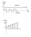
- FIG. 3 is a graph showing an example of the relationship between the applied voltage and the time in the step of forming an anodic oxidation coating on the magnesium alloy member 10.
- FIG. 4 is a graph showing a transition in the voltage at a surface of a member main body 1 of the magnetic alloy member 10 obtained when the member main body 1 is treated with anodic oxidation at a constant voltage.
- FIG. 5 is a graph showing the relationship between the applied voltage and the time in a conventional step of forming a conventional anodic oxidation coating.
- FIG. 6 is a graph showing another example of the relationship between the applied voltage and the time in the step of forming an anodic oxidation coating of the magnesium alloy member 10.
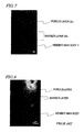
- FIG. 7 is a micrograph of a cross-section of the magnesium alloy member 10.
- FIG. 8 is a micrograph of a cross-section of a conventional magnesium alloy member.
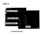
- FIG. 9 is a micrograph showing the sites of the magnesium alloy member 10 subjected to EDX analysis.
- FIG. 10 is a side view schematically showing a motorcycle.
- FIG. 11 is a perspective view schematically showing a frame of the motorcycle.
- FIG. 12 is an exploded perspective view schematically showing a crankcase.
- FIG. 13 is a perspective view schematically showing a wheel.
- FIG. 1 shows a cross-section of a magnesium alloy member (hereinafter, also referred to simply as the "member") 10 according to a preferred embodiment.
- the member 10 includes a member main body 1 and an anodic oxidation coating 2 covering at least a portion of the member main body 1.
- the anodic oxidation coating 2 may be coated with a paint film when necessary.
- the member main body 1 is formed of a magnesium alloy containing aluminum.
- the magnesium alloy any of various compositions is usable. Examples of usable additive elements other than aluminum include manganese, zinc, calcium, rare earth elements and the like.
- the member main body 1 is molded into a prescribed shape by, for example, casting.
- the anodic oxidation coating 2 has a multiple layer structure, and includes a first layer 2a which is a porous layer, and a second layer 2b located between the first layer 2 and the member main body 1.
- the anodic oxidation coating 2 includes the second layer 2b and the first layer 2a stacked in this order from the member main body 1 side.
- the first layer 2a is mainly formed of magnesium oxide (MgO) and magnesium hydroxide (MgOH), and is porous as described above.
- the second layer 2b is mainly formed of spinel.
- Spinel is an oxide of magnesium and aluminum, and has a stoichiometric composition of AlMg 2 O 4 (not necessarily limited to this, needless to say).
- the second layer 2b has a higher aluminum content than that of the first layer 2a and is substantially non-porous.
- the porous first layer 2a will also be referred to as the "porous layer”
- the non-porous second layer 2b will also be referred to as the "barrier layer”.
- the barrier layer 2b is a layer which is first formed when the member main body 1 is treated with anodic oxidation.
- the porous layer 2a is formed on the barrier layer 2b after the barrier layer 2b is formed.
- the porous layer 2a preferably has a porosity of 10% or higher and 50% or lower, whereas the barrier layer 2b preferably has a porosity of lower than 10%, and more preferably 5% or lower.
- the aluminum content of the porous layer 2a is preferably 1% by mass or higher and 10% by mass or lower, whereas the aluminum content of the barrier layer 2b is preferably 10% by mass or higher and 20% by mass or lower.
- the porous layer 2a preferably has an average pore diameter of micropores of 10 nm or larger and 4.5 ⁇ m or smaller, whereas the average pore diameter of the non-porous barrier layer 2b is not defined (needless to say, there are a very small number of holes in actuality).
- the ratio of a thickness t b of the barrier layer 2b with respect to a thickness t of the anodic oxidation coating 2 preferably is 5% or higher and 20%or lower.
- the ratio of the thickness of the barrier layer with respect to the thickness of the anodic oxidation coating preferably is 1% or higher but lower than 5%.
- the porous layer 2a is porous and has a higher porosity than that of the barrier layer 2b. Therefore, the actual thickness of the porous layer 2a is locally varied, and the porous layer 2a has a portion having a very small thickness.
- the barrier layer 2b is non-porous and has a lower porosity than that of the porous layer 2a. Therefore, the thickness of the barrier layer 2b is less varied than that of the porous layer 2a. For this reason, the corrosion resistance of the entire anodic oxidation coating 2 can be uniformly improved by forming the barrier layer 2b so as to be thick. More specifically, the barrier layer 2b significantly contributes to the improvement of the corrosion resistance.
- the ratio of the thickness t b of the barrier layer 2b with respect to the thickness t of the anodic oxidation coating 2 preferably is 5% or higher and 20% or lower, which is higher than that in the conventional art. Therefore, the thickness t b of the barrier layer 2b can be increased without particularly increasing the entire thickness t of the anodic oxidation coating 2 or a thickness t a of the porous layer 2a. This can further improve the corrosion resistance while suppressing the decrease in the fatigue strength. In other words, the magnesium alloy member 10 which is superb both in fatigue strength and corrosion resistance is obtained.
- the anodic oxidation coating 2 in which the thickness t b of the barrier layer 2b has a higher ratio than in the conventional art with respect to the thickness t of the anodic oxidation coating 2 can be produced by, for example, the following technique.
- the entire thickness t of the anodic oxidation coating 2 preferably is 2 ⁇ m or larger and 5 ⁇ m or smaller
- a sufficient fatigue strength and a sufficient corrosion resistance are obtained by forming the barrier layer 2b with a thickness which preferably is 200 nm or larger and 500 nm or smaller.
- FIG. 2 is a flowchart illustrating the method for producing the magnesium alloy member 10.
- the member main body 1 formed of a magnesium alloy containing aluminum is prepared (step S1).
- the member main body 1 has a higher aluminum content in the vicinity of a surface thereof (i.e., in the vicinity of the anodic oxidation coating 2 to be formed later) than in a central area in a thickness direction thereof.
- the barrier layer 2b is a layer formed by oxidizing a portion of the member main body 1 in the vicinity of the surface thereof. Therefore, in the case where the member main body 1 has a higher aluminum content in the vicinity of the surface, the barrier layer 2b having a larger thickness can be formed than in the case where the aluminum content is substantially the same throughout the entirety of the member main body 1 even though the amount of aluminum is the same.
- the member main body 1 may be formed by any of various known methods, but metal mold casting with a high cooling rate, especially die-casting is preferable. With die-casting, the molten magnesium alloy containing aluminum is rapidly cooled. This allows the aluminum content in the vicinity of the surface of the member main body 1 to be higher than that of an inner portion of the member main body 1. For the reasons described below, it is preferable that the magnesium alloy has a smaller average crystalline diameter in the vicinity of the surface of the member main body 1 than in the inner portion thereof. This is made possible by die-casting.
- the aluminum content in the vicinity of the surface of the member main body 1 preferably is 5.5% by mass or larger and 10.0% by mass or lower.
- the aluminum content is lower than 5.5% by mass, the formation of spinel is inhibited and thus the barrier layer 2b having a sufficient thickness may not be formed.
- the aluminum content is higher than 10.0% by mass, the tenacity of the magnesium alloy is reduced to be inappropriate for being used for the magnesium alloy member.
- the aluminum content in the vicinity of the surface of the member main body 1 preferably can be 5.5% by mass or larger and 10.0% by mass or lower by molding the member main body 1 by die-casting using a magnesium alloy such as, for example, AM60B, AM80, AZ91D, AZ61 or the like.
- the member main body 1 is sequentially treated with degreasing, water rinsing, removal of outermost surface layer, water rinsing, surface adjustment, and water rinsing (steps S2 through S7).
- Degreasing is to remove an oil component attached to the surface of the member main body 1.
- Removal of the outermost surface layer is to remove a contaminated surface layer from the surface of the member main body 1.
- Surface adjustment is to remove byproducts generated on the surface of the member main body 1 by the removal of the outermost surface layer and thus to clean the surface.
- the steps from degreasing to surface adjustment are not absolutely necessary, but it is preferable to carry out these steps depending on the member main body 1.
- the member main body 1 is a die-cast mold with a release agent attached thereto, it is preferable to carry out these steps.
- the anodic oxidation coating 2 is formed on the surface of the member main body 1 (step S8).
- This step of forming the anodic oxidation coating 2 is carried out by repeating, a plurality of times, an anodic oxidation step of treating the member main body 1 with anodic oxidation at a prescribed voltage for a prescribed time period.
- FIG. 3 shows an example of the relationship between the applied voltage and the time in step S8.
- the anodic oxidation step is repeated 10 times (from steps S8-1 to S8-10). Also as shown in FIG. 3 , the anodic oxidation step at each of the second and subsequent times is carried out at a voltage higher than the voltage used for the immediately previous time.
- an alkaline solution of any of various known compositions is usable.
- easily available alkaline solutions aqueous solutions of NaHCO 3 or aqueous solutions of NaOH having a concentration of 0.5 to 2 mol/l were preferably used.
- the current density preferably was 8 A/dm 2 to 15 A/dm 2 .
- step S9 through S12 water rinsing, post-treatment, pure water rinsing and drying are sequentially performed.
- post-treatment for example, pore closure treatment of closing the micropores on the surface of the anodic oxidation coating 2 is performed.
- the magnesium alloy member 10 including the anodic oxidation coating 2 is completed.
- step S8 of forming the anodic oxidation coating 2 is carried out by repeating, a plurality of times, the anodic oxidation step of treating the member main body 1 with anodic oxidation at a prescribed voltage for a prescribed time period.
- the anodic oxidation step at each of the second and subsequent times is carried out at a voltage higher than the voltage used for the immediately previous time. More specifically, during the step of forming the anodic oxidation coating 2, the applied voltage is raised step by step.
- Such a manner of forming the anodic oxidation coating 2 allows the ratio of the thickness t b of the barrier layer 2b with respect to the thickness t of the anodic oxidation coating 2 preferably to be 5% or higher and 20% or lower, which is higher than that in the conventional art. The reason for this will now be described with reference to FIG. 4 .
- FIG. 4 shows a transition in the voltage at the surface of the member main body 1 obtained when the member main body 1 is treated with anodic oxidation at a constant voltage.
- the voltage at the surface of the member main body 1 is gradually raised from immediately after the voltage application, and finally is converged to a certain value.
- Such a voltage transition is divided into four stages A through D by the generation state of the anodic oxidation coating 2.
- the voltage is rapidly raised, and the barrier layer 2b containing spinel as a main component is generated on the surface of the member main body 1.
- the barrier layer 2b is generated as in the first stage A, but the voltage is raised more slowly and the generation rate of the barrier layer 2b is slower.
- the porous layer 2a containing magnesium oxide or magnesium hydroxide containing as a main component is generated. The voltage keeps on rising slightly, and the barrier layer 2b is also generated although in a very small amount.
- the final stage D only the porous layer 2a is generated. The voltage is substantially converged to a constant value.
- the anodic oxidation steps at each of the second and subsequent times is carried out at a higher voltage than the voltage used for the immediately previous time, so as to repeat the stages A and B (i.e., the stages in which the barrier layer 2b is generated).
- the ratio of the thickness t b of the barrier layer 2b with respect to the thickness t of the anodic oxidation coating 2 can be made higher (practically 5% or higher and 20% or lower) than that in the conventional art.
- the thickness t b of the barrier layer 2b can be increased without increasing the entire thickness t of the anodic oxidation coating 2. This can further improve the corrosion resistance while preventing the decrease in the fatigue strength.
- the magnesium alloy member 10 which is superb both in fatigue strength and corrosion resistance, is obtained.
- the anodic oxidation is performed at the same voltage throughout the step of forming the anodic oxidation coating. Therefore, the ratio of the thickness of the barrier layer with respect to the entire thickness of the anodic oxidation coating cannot be sufficiently high.
- FIG. 3 shows the case where a plurality of anodic oxidation steps S8-1 through S8-10 with different applied voltages are continuously carried out.
- anodic oxidation steps S8-1 through S8-6 may be carried out non-continuously, i.e., intermittently.
- each anodic oxidation step preferably is carried out at a voltage of 40 V or higher and 150 V or lower.
- the voltage is lower than 40 V, the formation of spinel is inhibited and thus the barrier layer 2b having a sufficient thickness may not be formed.
- the voltage is higher than 150 V, the thickness t b of the barrier layer 2b is varied and is not likely to be uniform, which may reduce the productivity.
- the voltage for the first anodic oxidation step is preferably 75 V or higher and 120 V or lower.
- each anodic oxidation step is carried out for a time period of 0.001 seconds or longer and 120 seconds or shorter. It is basically more preferable that the time spent for each anodic oxidation step is shorter. However, when the time period is shorter than 0.001 seconds, the time of voltage application is excessively short and the generation rate of the coating may be significantly reduced. In consideration of the cost and productivity, the time period for each anodic oxidation step is preferably 0.001 seconds or longer. When the time period is longer than 120 seconds, the growth rate of the first layer is increased and thus the ratio of the thickness t b of the second layer 2b with respect to the entire thickness t of the anodic oxidation coating 2 is decreased.
- the time period for each anodic oxidation step is preferably 120 seconds or shorter, and more preferably 90 seconds or shorter.
- the entire step of forming the anodic oxidation coating 2 is typically carried out preferably for 5 to 50 minutes.
- the anodic oxidation step In order to increase the ratio of the thickness t b of the barrier layer 2b with respect to the thickness t of the anodic oxidation coating 2, it is preferable to carry out the anodic oxidation step at least a certain number of times. Specifically, it is preferable to carry out the anodic oxidation step at least five times.
- the difference in the voltage between one anodic oxidation step and the immediately subsequent anodic oxidation step is large to a certain degree.
- the anodic oxidation step at each of the second and subsequent times is carried out at a voltage higher by at least 0.5 V than the voltage used for the immediately previous time. It should be noted that when the voltage difference is excessively large, it may be difficult to repeat the anodic oxidation step many times and still maintain the voltage in the final anodic oxidation step (final voltage) at a level which does not reduce the productivity (for example, 150 V or lower as described above).
- the anodic oxidation step at each of the second and subsequent times is preferably carried out at a voltage which is not different, by more than 5.0 V, from the voltage used for the immediately previous time.
- the anodic oxidation step at each of the second and subsequent times is preferably carried out at a voltage which is higher, by 0.5 V or more and 5.0 V or less, than the voltage used for the immediately previous time.
- each anodic oxidation step the dissolution of the member main body 1 in the vicinity of the surface thereof and the generation of the anodic oxidation coating 2 occur at the same time in parallel. Therefore, where the average crystalline diameter in the vicinity of the surface of the member main body 1 (average crystalline diameter of the magnesium alloy) is sufficiently small, the surface is unlikely to be roughened when the member main body 1 is dissolved in the vicinity of the surface thereof and thus the variance of the thickness t b of the barrier layer 2b (area-by area variance) can be suppressed.
- the average crystalline diameter of the member main body 1 in an area within 100 ⁇ m from the interface with the anodic oxidation coating 2 is 20 ⁇ m or smaller, the effect of suppressing the variance of the thickness t b of the barrier layer 2b is large.
- the surface roughness of the member main body 1 used for the anodic oxidation step is small.
- the member main body 1 preferably has a 10 point average surface roughness of 3.2 Rz or smaller.
- the 10 point average surface roughness of the anodic oxidation coating 2 is 6.4 Rz or smaller.
- the magnesium alloy member 10, in which the 10 point average surface roughness of the anodic oxidation coating 2 preferably is 6.4 Rz or smaller is considered to have a sufficiently small variance of the thickness t b of the barrier layer 2.
- the surface roughness of the member main body 1 can be decreased by performing a treatment for smoothing the surface of the member main body 1 during the step of removing the outermost surface layer (step S4 in FIG. 2 ).
- the surface roughness of the member main body 1 can be decreased by using a fine grit polisher (for example, by polishing using emery paper of #400 to #500).
- the temperature and the concentration of the treating solution may be reduced to extend the treating time than in the conventional art.
- the surface roughness of the member main body 1 can be sufficiently decreased (for example, to a 10 point average surface roughness of 3.2 Rz or smaller) by immersing the member main body 1 in an acidic solution having a concentration of 0.1 mol/l or higher and 1.0 mol/l or lower and a temperature of 25°C or higher and 40°C or lower (for example, a phosphoric acid solution or a nitric acid solution) for a time period of 60 seconds or longer and 300 seconds or shorter.
- FIG. 7 shows a micrograph of a cross-section of the magnesium alloy member 10 produced by the production method according to a preferred embodiment.
- FIG. 8 shows a micrograph of a cross-section of a magnesium alloy member produced by a conventional method. The cross-sections were observed using these micrographs to measure the thicknesses of the anodic oxidation coatings and the barrier layers.
- the entire thickness t of the anodic oxidation coating 2 was 5 ⁇ m or smaller
- the thickness t b of the barrier layer 2b was 200 nm to 500 nm.
- the thickness of the barrier layer was 60 nm to 300 nm, with the average value being smaller than 200 nm.
- the production method according to the present preferred embodiment can form the barrier layer 2b so as to be thicker than by the conventional method.
- Tables 1 and 2 show the results of EDX analysis (energy dispersive X-ray spectrometry) performed on the magnesium alloy member 10 produced by the production method according to the present preferred embodiment. As shown in FIG. 9 , the EDX analysis was performed on four sites, i.e., analysis sites 1 and 2 corresponding to the porous layer 2a, analysis site 3 corresponding to the barrier layer 2b, and analysis site 4 corresponding to the member main body 1.
- EDX analysis energy dispersive X-ray spectrometry
- the aluminum content of the barrier layer 2b is higher than that of the porous layer 2a. From this result, it is understood that the barrier layer 2b is mainly formed of spinel and the porous layer 2a is mainly formed of magnesium oxide or magnesium hydroxide.
- Table 3 shows the results of evaluation of the corrosion resistance and the fatigue strength made on magnesium alloy members 10 produced by the production method according to the present preferred embodiment (Examples 1 through 6) and magnesium alloy members produced by conventional production methods (Comparative Examples 1 through 3).
- the voltage application conditions and the time period of each anodic oxidation step in Examples 1 through 6 and Comparative Examples 1 through 3 shown in Table 3 are as shown in Table 4.
- Example 2 Starting voltage: 60 V; Increased by 0.5 V; Final voltage: 140 V 1 sec.
- Example 3 Starting voltage: 70 V; Increased by 1.0 V; Final voltage: 150 V 1 sec.
- Example 4 Starting voltage: 60 V; Increased by 0.5 V; Final voltage: 110 V 0.1 sec.
- Example 5 Starting voltage: 60 V; Increased by 1.0 V; Final voltage: 110 V 1 sec.
- Example 6 Starting voltage: 40 V; Increased by 1.0 V; Final voltage: 140 V 1 sec. Comparative Example 1 DC, 200 V 30 min. Comparative Example 2 AC, 400 V, 1000 Hz 10 min. Comparative Example 3 DC, 300 V 45 min.
- the ratio of the thickness t b of the barrier layer 2b with respect to the thickness t of the anodic oxidation coating 2 is high (5% or higher and 20% or lower). Owing to such a thick barrier layer 2b, the corrosion resistance is superb. Since the entire thickness t itself of the anodic oxidation coating 2 is not so large, the fatigue strength is also superb.
- Comparative Examples 1 through 3 the ratio of the thickness of the barrier layer with respect to the thickness of the anodic oxidation coating is low (specifically, lower than 5%). For this reason, the barrier layer is excessively thin and thus the corrosion resistance is insufficient as in Comparative Example 1, or the anodic oxidation coating is excessively thick and thus the fatigue strength is insufficient as in Comparative Examples 2 and 3.
- Table 4 shows that the time period for each anodic oxidation step is 1 or 0.1 seconds, as an example, in each of Examples 1 through 6, but the time period for each anodic oxidation step may be shorter, for example, 0.001 seconds.
- the magnesium alloy member 10 is superb in corrosion resistance and fatigue strength, and therefore is preferably used for various types of transporters including a motorcycle 100 as shown in FIG. 10 .
- Transporters are mainly used outdoors and so the members forming the transporters are often exposed to severe environments.
- Use of the magnesium alloy member 10 according to preferred embodiments for a transporter reduces the weight thereof, prevents the corrosion even under severe environments, and improves the durability thereof.
- the magnesium alloy member 10 is, for example, a frame 20 of the motorcycle shown in FIG. 11 .
- the magnesium alloy member 10 according to a preferred embodiment is, for example, a crankcase 30 shown in FIG. 12 or a wheel 40 shown in FIG. 13 .
- the magnesium alloy member 10 according to the various preferred embodiments is not limited to being used for these exemplary applications, and may be preferably used as various other members of transporters.
- a magnesium alloy member superb both in corrosion resistance and fatigue strength, and a method for producing the same, are provided.
- the magnesium alloy member according to the preferred embodiments of the present invention is widely usable for vehicles such as, for example, motorcycles and four-wheel automobiles and also various other transporters such as, for example, watercrafts and aircrafts.
Landscapes
- Chemical & Material Sciences (AREA)
- Engineering & Computer Science (AREA)
- Materials Engineering (AREA)
- Metallurgy (AREA)
- Organic Chemistry (AREA)
- Mechanical Engineering (AREA)
- Chemical Kinetics & Catalysis (AREA)
- Electrochemistry (AREA)
- Life Sciences & Earth Sciences (AREA)
- Environmental & Geological Engineering (AREA)
- General Life Sciences & Earth Sciences (AREA)
- Geology (AREA)
- Manufacturing & Machinery (AREA)
- Other Surface Treatments For Metallic Materials (AREA)
- Powder Metallurgy (AREA)
Abstract
The anodisation process includes a plurality of successive anodisation steps with incrementally increasing voltage in a range of 40 V to 150 V.
Description
- The present invention relates to a magnesium alloy member, and in particular to a magnesium alloy member including an anodic oxidation coating. The present invention also relates to a method for producing such a magnesium alloy member and a transporter including such a magnesium alloy member.
- Conventionally, steel has widely been used as a material for transporters because of superior mechanical properties, superior processability and low cost thereof. In order to improve the fuel efficiency and running performance, however, transporters are desired to be more lightweight. Research has been made to use materials more lightweight than steel.
- Recently, low-cost refining methods for titanium, aluminum, magnesium and the like, which have a lower specific gravity than that of steel, and methods for producing alloys containing such metal materials have been developed. Technologies for improving the strength and processability of alloys of such metal materials have also been developed.
- In such a situation, it has been proposed to use alloys of titanium, aluminum and magnesium as materials for members of transporters. Particularly, when magnesium alloys are used, the weight of the transporters can be significantly reduced because the density of magnesium is about 23% of that of steel.
- However, magnesium alloys are more likely to be corroded than aluminum alloys in certain environments. As one technique to improve the corrosion resistance of magnesium alloys, an anodic oxidation coating is formed on a surface of a magnesium alloy.
- An anodic oxidation coating on an aluminum alloy is known to include a porous layer and a non-porous barrier layer. These layers can be observed by an electron microscope. An anodic oxidation coating on a magnesium alloy also includes a porous layer and a barrier layer as disclosed in Japanese Laid-Open Patent Publication No.
2006-291278 - This publication describes that the corrosion resistance of magnesium alloys can be improved by reducing an average diameter of micropores in a surface area of the porous layer from that in the conventional art to 100 nm to 25 µm.
- However, transporters are mainly used outdoors and therefore members forming the transporters are often exposed to severe environments. Hence, magnesium alloys are desired to have more improved corrosion resistance.
- Most of the magnesium alloy members practically used today are used for domestic electronic appliances, particularly for reducing the weight of small mobile devices. The magnesium alloy members for these applications are small interior components and are not required to have such a high corrosion resistance as is required of those used for transporters.
- In general, as the anodic oxidation coating is thicker, the corrosion resistance is higher. An anodic oxidation coating formed on a magnesium alloy member used for domestic electronic appliances often has a thickness of about 5 µm to 15 µm. When an anodic oxidation coating of such a thickness is formed on a magnesium alloy member for transporters by a conventional technique, a sufficient corrosion resistance is not provided. Studies performed by the present inventors have found that a thickness exceeding 15 µm is required in order to guarantee a sufficient corrosion resistance for a magnesium alloy member used for transporters.
- However, when the anodic oxidation coating is thickened, the porous layer is also thickened accordingly. A porous layer, which is mainly formed of magnesium oxide (MgO) or magnesium hydroxide (MgOH), has a convex and concave surface and thus is more brittle than the magnesium alloy which is the starting material. When the porous layer is thickened, and the height difference between the convex area and the concave area becomes large, such a location with a large height difference is likely to cause fatigue destruction and thus decrease the fatigue strength.
- In order to overcome the problems described above, preferred embodiments of the present invention provide a method for improving the corrosion resistance of a magnesium alloy without increasing the thickness of the anodic oxidation coating, or even while further reducing the thickness of the anodic oxidation coating than that in the conventional art.
- In addition, preferred embodiments of the present invention provide a magnesium alloy member which is superb both in corrosion resistance and fatigue strength, a method for producing the same, and a transporter including such a magnesium alloy member.
- A preferred embodiment of the present invention provides a magnesium alloy member including a member main body formed of a magnesium alloy containing aluminum, and an anodic oxidation coating covering at least a portion of the member main body. The anodic oxidation coating includes a porous first layer and a second layer located between the first layer and the member main body and having a higher aluminum content than that of the first layer. The ratio of a thickness of the second layer with respect to a thickness of the anodic oxidation coating is preferably 5% or higher and 20% or lower.
- In one preferred embodiment, the aluminum content of the second layer is preferably 10% by mass or higher and 20% by mass or lower.
- In one preferred embodiment, the thickness of the anodic oxidation coating is preferably 2 µm or larger and 5 µm or smaller, and the thickness of the second layer is preferably 200 nm or larger and 500 nm or smaller.
- In one preferred embodiment, the first layer preferably has a porosity of 10% or higher; and the second layer preferably has a porosity of lower than 10%.
- In one preferred embodiment, the member main body preferably has an aluminum content of 5.5% by mass or higher and 10.0% by mass or lower in an area within 100 µm from an interface with the anodic oxidation coating.
- In one preferred embodiment, the member main body preferably has an average crystalline diameter of 20 µm or smaller in an area within 100 µm from an interface with the anodic oxidation coating.
- In one preferred embodiment, the anodic oxidation coating preferably has a 10 point average surface roughness of 6.4 Rz or smaller at a surface thereof.
- Alternatively, a magnesium alloy member according to a preferred embodiment of the present invention includes a member main body formed of a magnesium alloy containing aluminum; and an anodic oxidation coating covering at least a portion of the member main body. The anodic oxidation coating includes a porous first layer and a second layer located between the first layer and the member main body and having a higher aluminum content than that of the first layer. The anodic oxidation coating preferably has a thickness of 2 µm or larger and 5 µm or smaller; and the second layer preferably has a thickness of 200 nm or larger and 500 nm or smaller.
- A transporter according to a preferred embodiment of the present invention includes a magnesium alloy member having the above-described structure.
- A method for producing a magnesium alloy member according to a preferred embodiment of the present invention includes the steps of preparing a member main body formed of a magnesium alloy containing aluminum; and forming an anodic oxidation coating on a surface of the member main body. The step of forming the anodic oxidation coating is carried out by repeating, a plurality of times, an anodic oxidation step of treating the member main body with anodic oxidation at a prescribed voltage for a prescribed time period; and the anodic oxidation step at each of the second and subsequent times is carried out at a voltage higher than the voltage used for the immediately previous time.
- In one preferred embodiment, the anodic oxidation step is carried out at a voltage of preferably 40 V or higher and 150 V or lower.
- In one preferred embodiment, the anodic oxidation step at each time is carried out for a time period of preferably 0.001 seconds or longer and 120 seconds or shorter.
- In one preferred embodiment, the anodic oxidation step at each of the second and subsequent times is carried out at a voltage higher than the voltage used for the immediately previous time preferalby by 0.5 V or more and 5.0 V or less.
- In one preferred embodiment, the anodic oxidation step is repeated at least five times.
- In one preferred embodiment, the step of preparing the member main body includes the step of molding the member main body from the magnesium alloy containing aluminum by die-casting.
- In one preferred embodiment, the method for producing a magnesium alloy member according to the present invention further includes the step of, before the step of forming the anodic oxidation coating, immersing the member main body in an acidic solution preferably having a concentration of 0.1 mol/1 or higher and 1.0 mol/l or lower and a temperature of 25°C or higher and 40°C or lower for a time period of 60 seconds or longer and 300 seconds or shorter.
- The anodic oxidation coating of the magnesium alloy member according to a preferred embodiment of the present invention includes a porous first layer and a second layer located between the first layer and the member main body and having a higher aluminum content than that of the first layer. In the magnesium alloy member according to a preferred embodiment of the present invention, the ratio of the thickness of the second layer with respect to the thickness of the anodic oxidation coating is preferably 5% or higher and 20% or lower, which is higher than that in the conventional art. Therefore, the thickness of the second layer can be increased without particularly increasing the entire thickness of the anodic oxidation coating. This can further improve the corrosion resistance while preventing the decrease in the fatigue strength. In other words, the magnesium alloy member which is superb both in the fatigue strength and the corrosion resistance is obtained.
- The aluminum content of the second layer preferably is typically 10% by mass or higher and 20% by mass or lower.
- Where the thickness of the anodic oxidation coating is 2 µm or larger and 5 µm or smaller, a sufficient fatigue strength and a sufficient corrosion resistance are obtained by, for example, forming the second layer with a thickness which is 200 nm or larger and 500 nm or smaller.
- The first layer preferably has a porosity of 10% or higher, whereas the second layer preferably has a porosity of lower than 10%, and more preferably 5% or lower.
- It is preferable that the aluminum content in the vicinity of the surface of the member main body (more practically, an area within 100 µm from the interface between the member main body and the anodic oxidation coating) preferably is 5.5% by mass or larger and 10.0% by mass or lower. When the aluminum content is lower than 5.5% by mass, the formation of spinel (an oxide of magnesium and aluminum as described below) is inhibited and thus the second layer having a sufficient thickness may not be formed. When the aluminum content is higher than 10.0% by mass, the tenacity of the magnesium alloy is reduced to be inappropriate for being used for the magnesium alloy member.
- During each anodic oxidation step, the dissolution of the member main body in the vicinity of the surface thereof and the generation of the anodic oxidation coating occur at the same time in parallel. Therefore, where the average crystalline diameter in the vicinity of the surface of the member main body is sufficiently small, the surface is unlikely to be roughened when the member main body is dissolved in the vicinity of the surface thereof and thus, variations in the thickness of the second layer (area-by area variance) can be prevented. Specifically, where the average crystalline diameter of the member main body in an area within 100 µm from the interface with the anodic oxidation coating preferably is 20 µm or smaller, the effect of suppressing the variance of the thickness of the second layer is large.
- For the same reason (for the purpose of making the surface of the member main body less likely to be roughened when the member main body is dissolved in the vicinity of the surface so as to suppress the variance of the thickness of the second layer), it is preferable that the surface roughness of the member main body used for the anodic oxidation step is small. Specifically, the member main body preferably has a 10 point average surface roughness of 3.2 Rz or smaller. When the anodic oxidation coating is formed on the member main body having a 10 point average surface roughness 3.2 Rz or smaller, the 10 point average surface roughness of the anodic oxidation coating is 6.4 Rz or smaller. More specifically, the magnesium alloy member in which the 10 point average surface roughness of the anodic oxidation coating is 6.4 Rz or smaller has a sufficiently small variance of the thickness of the second layer.
- The magnesium alloy member according to the various preferred embodiments is superb in corrosion resistance and fatigue strength, and therefore is preferably used for various types of transporters.
- According to the production method of a magnesium alloy member of a preferred embodiment of the present invention, the step of forming an anodic oxidation coating is carried out by repeating, a plurality of times, an anodic oxidation step of treating the member main body with anodic oxidation at a prescribed voltage for a prescribed time period. The anodic oxidation step at each of the second and subsequent times is carried out at a higher voltage than the voltage used for the immediately previous time. More specifically, during the step of forming the anodic oxidation coating, the applied voltage is raised step by step. Such a manner of forming the anodic oxidation coating allows the ratio of the thickness of the second layer with respect to the thickness of the anodic oxidation coating preferably to be 5% or higher and 20% or lower, which is higher than that in the conventional art. For this reason, the thickness of the second layer can be increased without increasing the entire thickness of the anodic oxidation coating. This can further improve the corrosion resistance while preventing the decrease in the fatigue strength. In other words, the magnesium alloy member which is superb both in fatigue strength and corrosion resistance is obtained.
- Preferably, each anodic oxidation step is carried out at a voltage of 40 V or higher and 150 V or lower. When the voltage is lower than 40 V, the formation of spinel is inhibited and thus the second layer having a sufficient thickness may not be formed. When the voltage is higher than 150 V, the thickness of the second layer is varied and is not likely to be uniform, which may reduce the productivity.
- Preferably, each anodic oxidation step is carried out for a time period of 0.001 seconds or longer and 120 seconds or shorter. It is basically more preferable as the time spent for each anodic oxidation step is shorter. However, when the time period is shorter than 0.001 seconds, the time of voltage application is excessively short and the generation rate of the coating may be significantly reduced. In consideration of the cost and productivity, the time period for each anodic oxidation step is preferably 0.001 seconds or longer. When the time period is longer than 120 seconds, the growth rate of the first layer is increased and thus the ratio of the thickness of the second layer with respect to the entire thickness of the anodic oxidation coating is decreased. In order to keep high the ratio of the thickness of the second layer, the time period for each anodic oxidation step is preferably 120 seconds or shorter, and more preferably 90 seconds or shorter.
- In order to form the second layer efficiently, it is preferable that the difference in the voltage between one anodic oxidation step and the immediately subsequent anodic oxidation step is large to a certain degree. Specifically, it is preferable that the anodic oxidation step at each of the second and subsequent times is carried out at a voltage higher, by at least 0.5 V, than the voltage used for the immediately previous time. It should be noted that when the voltage difference is excessively large, it may be difficult to repeat the anodic oxidation step many times and still maintain the voltage in the final anodic oxidation step (final voltage) at a level which is unlikely to vary the thickness of the second layer (for example, 150 V or lower as described above). Therefore, the anodic oxidation step at each of the second and subsequent times is preferably carried out at a voltage which is not different, by more than 5.0 V, than the voltage used for the immediately previous time. Consequently, the anodic oxidation step at each of the second and subsequent times is preferably carried out at a voltage which is higher, by 0.5 V or more and 5.0 V or less, than the voltage used for the immediately previous time.
- In order to increase the ratio of the thickness of the second layer with respect to the thickness of the anodic oxidation coating, it is preferable to carry out the anodic oxidation step at least a certain number of times. Specifically, it is preferable to carry out the anodic oxidation step at least five times.
- The step of preparing the member main body preferably includes the step of molding the member main body from the magnesium alloy containing aluminum by die-casting. With die-casting, the molten magnesium alloy containing aluminum is rapidly cooled. This allows the average crystalline diameter in the vicinity of the surface of the member main body to be smaller than that of an inner portion of the member main body.
- Before the step of forming the anodic oxidation coating, the step may be carried out of immersing the member main body in an acidic solution having a concentration of 0.1 mol/l or higher and 1.0 mol/l or lower and a temperature of 25°C or higher and 40°C or lower for a time period of 60 seconds or longer and 300 seconds or shorter. Thus, the surface roughness of the member main body can be sufficiently decreased (for example, to a 10 point average surface roughness of 3.2 Rz or smaller).
- According to the preferred embodiments of the present invention, a magnesium alloy member which is superb both in corrosion resistance and fatigue strength, and a method for producing the same are provided. Also according to another preferred embodiment of the present invention, a transporter including such a magnesium alloy member is provided.
- Other features, elements, steps, characteristics and advantages of the present invention will become more apparent from the following detailed description of preferred embodiments of the present invention with reference to the attached drawings.
-
FIG. 1 schematically shows a cross-sectional structure of amagnesium alloy member 10 according to a preferred embodiment of the present invention. -
FIG. 2 is a flowchart schematically illustrating a method for producing themagnesium alloy member 10. -
FIG. 3 is a graph showing an example of the relationship between the applied voltage and the time in the step of forming an anodic oxidation coating on themagnesium alloy member 10. -
FIG. 4 is a graph showing a transition in the voltage at a surface of a membermain body 1 of themagnetic alloy member 10 obtained when the membermain body 1 is treated with anodic oxidation at a constant voltage. -
FIG. 5 is a graph showing the relationship between the applied voltage and the time in a conventional step of forming a conventional anodic oxidation coating. -
FIG. 6 is a graph showing another example of the relationship between the applied voltage and the time in the step of forming an anodic oxidation coating of themagnesium alloy member 10. -
FIG. 7 is a micrograph of a cross-section of themagnesium alloy member 10. -
FIG. 8 is a micrograph of a cross-section of a conventional magnesium alloy member. -
FIG. 9 is a micrograph showing the sites of themagnesium alloy member 10 subjected to EDX analysis. -
FIG. 10 is a side view schematically showing a motorcycle. -
FIG. 11 is a perspective view schematically showing a frame of the motorcycle. -
FIG. 12 is an exploded perspective view schematically showing a crankcase. -
FIG. 13 is a perspective view schematically showing a wheel. - Hereinafter, the present invention will be described by way of preferred embodiments with reference to the drawings. The present invention is not limited in any way by the following
-
FIG. 1 shows a cross-section of a magnesium alloy member (hereinafter, also referred to simply as the "member") 10 according to a preferred embodiment. As shown inFIG. 1 , themember 10 includes a membermain body 1 and ananodic oxidation coating 2 covering at least a portion of the membermain body 1. Although not shown inFIG. 1 , theanodic oxidation coating 2 may be coated with a paint film when necessary. - The member
main body 1 is formed of a magnesium alloy containing aluminum. As the magnesium alloy, any of various compositions is usable. Examples of usable additive elements other than aluminum include manganese, zinc, calcium, rare earth elements and the like. The membermain body 1 is molded into a prescribed shape by, for example, casting. - The
anodic oxidation coating 2 has a multiple layer structure, and includes afirst layer 2a which is a porous layer, and asecond layer 2b located between thefirst layer 2 and the membermain body 1. In other words, theanodic oxidation coating 2 includes thesecond layer 2b and thefirst layer 2a stacked in this order from the membermain body 1 side. - The
first layer 2a is mainly formed of magnesium oxide (MgO) and magnesium hydroxide (MgOH), and is porous as described above. By contrast, thesecond layer 2b is mainly formed of spinel. Spinel is an oxide of magnesium and aluminum, and has a stoichiometric composition of AlMg2O4 (not necessarily limited to this, needless to say). As is seen from the formula of the main component, thesecond layer 2b has a higher aluminum content than that of thefirst layer 2a and is substantially non-porous. Hereinafter, the porousfirst layer 2a will also be referred to as the "porous layer", and the non-poroussecond layer 2b will also be referred to as the "barrier layer". Thebarrier layer 2b is a layer which is first formed when the membermain body 1 is treated with anodic oxidation. Theporous layer 2a is formed on thebarrier layer 2b after thebarrier layer 2b is formed. - The
porous layer 2a preferably has a porosity of 10% or higher and 50% or lower, whereas thebarrier layer 2b preferably has a porosity of lower than 10%, and more preferably 5% or lower. The aluminum content of theporous layer 2a is preferably 1% by mass or higher and 10% by mass or lower, whereas the aluminum content of thebarrier layer 2b is preferably 10% by mass or higher and 20% by mass or lower. - The
porous layer 2a preferably has an average pore diameter of micropores of 10 nm or larger and 4.5 µm or smaller, whereas the average pore diameter of thenon-porous barrier layer 2b is not defined (needless to say, there are a very small number of holes in actuality). - In the
magnesium alloy member 10 according to the present preferred embodiment, the ratio of a thickness tb of thebarrier layer 2b with respect to a thickness t of theanodic oxidation coating 2 preferably is 5% or higher and 20%or lower. By contrast, in the conventional magnesium alloy member, the ratio of the thickness of the barrier layer with respect to the thickness of the anodic oxidation coating preferably is 1% or higher but lower than 5%. - The
porous layer 2a is porous and has a higher porosity than that of thebarrier layer 2b. Therefore, the actual thickness of theporous layer 2a is locally varied, and theporous layer 2a has a portion having a very small thickness. By contrast, thebarrier layer 2b is non-porous and has a lower porosity than that of theporous layer 2a. Therefore, the thickness of thebarrier layer 2b is less varied than that of theporous layer 2a. For this reason, the corrosion resistance of the entireanodic oxidation coating 2 can be uniformly improved by forming thebarrier layer 2b so as to be thick. More specifically, thebarrier layer 2b significantly contributes to the improvement of the corrosion resistance. - In the present preferred embodiment, as described above, the ratio of the thickness tb of the
barrier layer 2b with respect to the thickness t of theanodic oxidation coating 2 preferably is 5% or higher and 20% or lower, which is higher than that in the conventional art. Therefore, the thickness tb of thebarrier layer 2b can be increased without particularly increasing the entire thickness t of theanodic oxidation coating 2 or a thickness ta of theporous layer 2a. This can further improve the corrosion resistance while suppressing the decrease in the fatigue strength. In other words, themagnesium alloy member 10 which is superb both in fatigue strength and corrosion resistance is obtained. Theanodic oxidation coating 2 in which the thickness tb of thebarrier layer 2b has a higher ratio than in the conventional art with respect to the thickness t of theanodic oxidation coating 2 can be produced by, for example, the following technique. - Where, for example, the entire thickness t of the
anodic oxidation coating 2 preferably is 2 µm or larger and 5 µm or smaller, a sufficient fatigue strength and a sufficient corrosion resistance are obtained by forming thebarrier layer 2b with a thickness which preferably is 200 nm or larger and 500 nm or smaller. - Now, with reference to
FIG. 2 , a method for producing themagnesium alloy member 10 according to the present preferred embodiment will be described.FIG. 2 is a flowchart illustrating the method for producing themagnesium alloy member 10. - First, the member
main body 1 formed of a magnesium alloy containing aluminum is prepared (step S1). Preferably, the membermain body 1 has a higher aluminum content in the vicinity of a surface thereof (i.e., in the vicinity of theanodic oxidation coating 2 to be formed later) than in a central area in a thickness direction thereof. Thebarrier layer 2b is a layer formed by oxidizing a portion of the membermain body 1 in the vicinity of the surface thereof. Therefore, in the case where the membermain body 1 has a higher aluminum content in the vicinity of the surface, thebarrier layer 2b having a larger thickness can be formed than in the case where the aluminum content is substantially the same throughout the entirety of the membermain body 1 even though the amount of aluminum is the same. - The member
main body 1 may be formed by any of various known methods, but metal mold casting with a high cooling rate, especially die-casting is preferable. With die-casting, the molten magnesium alloy containing aluminum is rapidly cooled. This allows the aluminum content in the vicinity of the surface of the membermain body 1 to be higher than that of an inner portion of the membermain body 1. For the reasons described below, it is preferable that the magnesium alloy has a smaller average crystalline diameter in the vicinity of the surface of the membermain body 1 than in the inner portion thereof. This is made possible by die-casting. - It is preferable that the aluminum content in the vicinity of the surface of the member main body 1 (more practically, an area within 100 µm from an interface between the member
main body 1 and the anodic oxidation coating 2) preferably is 5.5% by mass or larger and 10.0% by mass or lower. When the aluminum content is lower than 5.5% by mass, the formation of spinel is inhibited and thus thebarrier layer 2b having a sufficient thickness may not be formed. When the aluminum content is higher than 10.0% by mass, the tenacity of the magnesium alloy is reduced to be inappropriate for being used for the magnesium alloy member. The aluminum content in the vicinity of the surface of the membermain body 1 preferably can be 5.5% by mass or larger and 10.0% by mass or lower by molding the membermain body 1 by die-casting using a magnesium alloy such as, for example, AM60B, AM80, AZ91D, AZ61 or the like. - Next, the member
main body 1 is sequentially treated with degreasing, water rinsing, removal of outermost surface layer, water rinsing, surface adjustment, and water rinsing (steps S2 through S7). Degreasing is to remove an oil component attached to the surface of the membermain body 1. Removal of the outermost surface layer is to remove a contaminated surface layer from the surface of the membermain body 1. Surface adjustment is to remove byproducts generated on the surface of the membermain body 1 by the removal of the outermost surface layer and thus to clean the surface. These steps may be carried out by any of various known techniques. For example, the removal of the outermost surface layer may be performed mechanically or chemically. The steps from degreasing to surface adjustment are not absolutely necessary, but it is preferable to carry out these steps depending on the membermain body 1. For example, in the case where the membermain body 1 is a die-cast mold with a release agent attached thereto, it is preferable to carry out these steps. - Next, the
anodic oxidation coating 2 is formed on the surface of the member main body 1 (step S8). This step of forming theanodic oxidation coating 2 is carried out by repeating, a plurality of times, an anodic oxidation step of treating the membermain body 1 with anodic oxidation at a prescribed voltage for a prescribed time period. -
FIG. 3 shows an example of the relationship between the applied voltage and the time in step S8. In the example shown inFIG. 3 , the anodic oxidation step is repeated 10 times (from steps S8-1 to S8-10). Also as shown inFIG. 3 , the anodic oxidation step at each of the second and subsequent times is carried out at a voltage higher than the voltage used for the immediately previous time. - As an electrolyte for the anodic oxidation, an alkaline solution of any of various known compositions is usable. In examples described below, easily available alkaline solutions (aqueous solutions of NaHCO3 or aqueous solutions of NaOH) having a concentration of 0.5 to 2 mol/l were preferably used.
- As an electric current, a DC current is used but a PR current (having a DC-like waveform obtained as a result of a control on an AC current) is also usable. There is no specific limitation on the current density. In the examples, described below, the current density preferably was 8 A/dm2 to 15 A/dm2.
- Then, water rinsing, post-treatment, pure water rinsing and drying are sequentially performed (steps S9 through S12). As the post-treatment, for example, pore closure treatment of closing the micropores on the surface of the
anodic oxidation coating 2 is performed. Thus, themagnesium alloy member 10 including theanodic oxidation coating 2 is completed. - As described above, according to the production method in the present preferred embodiment, step S8 of forming the
anodic oxidation coating 2 is carried out by repeating, a plurality of times, the anodic oxidation step of treating the membermain body 1 with anodic oxidation at a prescribed voltage for a prescribed time period. The anodic oxidation step at each of the second and subsequent times is carried out at a voltage higher than the voltage used for the immediately previous time. More specifically, during the step of forming theanodic oxidation coating 2, the applied voltage is raised step by step. Such a manner of forming theanodic oxidation coating 2 allows the ratio of the thickness tb of thebarrier layer 2b with respect to the thickness t of theanodic oxidation coating 2 preferably to be 5% or higher and 20% or lower, which is higher than that in the conventional art. The reason for this will now be described with reference toFIG. 4 . -
FIG. 4 shows a transition in the voltage at the surface of the membermain body 1 obtained when the membermain body 1 is treated with anodic oxidation at a constant voltage. The voltage at the surface of the membermain body 1 is gradually raised from immediately after the voltage application, and finally is converged to a certain value. Such a voltage transition is divided into four stages A through D by the generation state of theanodic oxidation coating 2. - In the first stage A, the voltage is rapidly raised, and the
barrier layer 2b containing spinel as a main component is generated on the surface of the membermain body 1. In the next stage B, thebarrier layer 2b is generated as in the first stage A, but the voltage is raised more slowly and the generation rate of thebarrier layer 2b is slower. In the next stage C, theporous layer 2a containing magnesium oxide or magnesium hydroxide containing as a main component is generated. The voltage keeps on rising slightly, and thebarrier layer 2b is also generated although in a very small amount. In the final stage D, only theporous layer 2a is generated. The voltage is substantially converged to a constant value. - According to the production method in the present preferred embodiment, the anodic oxidation steps at each of the second and subsequent times is carried out at a higher voltage than the voltage used for the immediately previous time, so as to repeat the stages A and B (i.e., the stages in which the
barrier layer 2b is generated). As a result, the ratio of the thickness tb of thebarrier layer 2b with respect to the thickness t of theanodic oxidation coating 2 can be made higher (practically 5% or higher and 20% or lower) than that in the conventional art. For this reason, the thickness tb of thebarrier layer 2b can be increased without increasing the entire thickness t of theanodic oxidation coating 2. This can further improve the corrosion resistance while preventing the decrease in the fatigue strength. In other words, themagnesium alloy member 10, which is superb both in fatigue strength and corrosion resistance, is obtained. - By contrast, according to the conventional production method, as shown in
FIG. 5 , the anodic oxidation is performed at the same voltage throughout the step of forming the anodic oxidation coating. Therefore, the ratio of the thickness of the barrier layer with respect to the entire thickness of the anodic oxidation coating cannot be sufficiently high. -
FIG. 3 shows the case where a plurality of anodic oxidation steps S8-1 through S8-10 with different applied voltages are continuously carried out. Alternatively, as shown inFIG. 6 , anodic oxidation steps S8-1 through S8-6 may be carried out non-continuously, i.e., intermittently. - Preferably, each anodic oxidation step preferably is carried out at a voltage of 40 V or higher and 150 V or lower. When the voltage is lower than 40 V, the formation of spinel is inhibited and thus the
barrier layer 2b having a sufficient thickness may not be formed. When the voltage is higher than 150 V, the thickness tb of thebarrier layer 2b is varied and is not likely to be uniform, which may reduce the productivity. In order to shorten the time required for performing the anodic oxidation step a plurality of times, the voltage for the first anodic oxidation step (starting voltage) is preferably 75 V or higher and 120 V or lower. - Preferably, each anodic oxidation step is carried out for a time period of 0.001 seconds or longer and 120 seconds or shorter. It is basically more preferable that the time spent for each anodic oxidation step is shorter. However, when the time period is shorter than 0.001 seconds, the time of voltage application is excessively short and the generation rate of the coating may be significantly reduced. In consideration of the cost and productivity, the time period for each anodic oxidation step is preferably 0.001 seconds or longer. When the time period is longer than 120 seconds, the growth rate of the first layer is increased and thus the ratio of the thickness tb of the
second layer 2b with respect to the entire thickness t of theanodic oxidation coating 2 is decreased. In order to keep high the ratio of the thickness tb of thesecond layer 2b, the time period for each anodic oxidation step is preferably 120 seconds or shorter, and more preferably 90 seconds or shorter. The entire step of forming theanodic oxidation coating 2 is typically carried out preferably for 5 to 50 minutes. - In order to increase the ratio of the thickness tb of the
barrier layer 2b with respect to the thickness t of theanodic oxidation coating 2, it is preferable to carry out the anodic oxidation step at least a certain number of times. Specifically, it is preferable to carry out the anodic oxidation step at least five times. - In order to repeat the steps A and B, it is preferable that the difference in the voltage between one anodic oxidation step and the immediately subsequent anodic oxidation step is large to a certain degree. Specifically, it is preferable that the anodic oxidation step at each of the second and subsequent times is carried out at a voltage higher by at least 0.5 V than the voltage used for the immediately previous time. It should be noted that when the voltage difference is excessively large, it may be difficult to repeat the anodic oxidation step many times and still maintain the voltage in the final anodic oxidation step (final voltage) at a level which does not reduce the productivity (for example, 150 V or lower as described above). Therefore, the anodic oxidation step at each of the second and subsequent times is preferably carried out at a voltage which is not different, by more than 5.0 V, from the voltage used for the immediately previous time. Namely, the anodic oxidation step at each of the second and subsequent times is preferably carried out at a voltage which is higher, by 0.5 V or more and 5.0 V or less, than the voltage used for the immediately previous time.
- During each anodic oxidation step, the dissolution of the member
main body 1 in the vicinity of the surface thereof and the generation of theanodic oxidation coating 2 occur at the same time in parallel. Therefore, where the average crystalline diameter in the vicinity of the surface of the member main body 1 (average crystalline diameter of the magnesium alloy) is sufficiently small, the surface is unlikely to be roughened when the membermain body 1 is dissolved in the vicinity of the surface thereof and thus the variance of the thickness tb of thebarrier layer 2b (area-by area variance) can be suppressed. Specifically, where the average crystalline diameter of the membermain body 1 in an area within 100 µm from the interface with theanodic oxidation coating 2 is 20 µm or smaller, the effect of suppressing the variance of the thickness tb of thebarrier layer 2b is large. - For the same reason (for the purpose of making the surface of the member
main body 1 less likely to be roughened when the membermain body 1 is dissolved in the vicinity of the surface so as to suppress the variance of the thickness tb of thebarrier layer 2b), it is preferable that the surface roughness of the membermain body 1 used for the anodic oxidation step is small. Specifically, the membermain body 1 preferably has a 10 point average surface roughness of 3.2 Rz or smaller. When theanodic oxidation coating 2 is formed on the membermain body 1 having a 10 point average surface roughness 3.2 Rz or smaller, the 10 point average surface roughness of theanodic oxidation coating 2 is 6.4 Rz or smaller. More specifically, themagnesium alloy member 10, in which the 10 point average surface roughness of theanodic oxidation coating 2 preferably is 6.4 Rz or smaller, is considered to have a sufficiently small variance of the thickness tb of thebarrier layer 2. - The surface roughness of the member
main body 1 can be decreased by performing a treatment for smoothing the surface of the membermain body 1 during the step of removing the outermost surface layer (step S4 inFIG. 2 ). - Where, for example, the outermost surface layer is removed by mechanical polishing, the surface roughness of the member
main body 1 can be decreased by using a fine grit polisher (for example, by polishing using emery paper of #400 to #500). - Where the outermost surface layer is removed by etching which is a chemical technique, the temperature and the concentration of the treating solution (etchant) may be reduced to extend the treating time than in the conventional art. Specifically, the surface roughness of the member
main body 1 can be sufficiently decreased (for example, to a 10 point average surface roughness of 3.2 Rz or smaller) by immersing the membermain body 1 in an acidic solution having a concentration of 0.1 mol/l or higher and 1.0 mol/l or lower and a temperature of 25°C or higher and 40°C or lower (for example, a phosphoric acid solution or a nitric acid solution) for a time period of 60 seconds or longer and 300 seconds or shorter. -
FIG. 7 shows a micrograph of a cross-section of themagnesium alloy member 10 produced by the production method according to a preferred embodiment.FIG. 8 shows a micrograph of a cross-section of a magnesium alloy member produced by a conventional method. The cross-sections were observed using these micrographs to measure the thicknesses of the anodic oxidation coatings and the barrier layers. In themagnesium alloy member 10 shown inFIG. 7 , the entire thickness t of theanodic oxidation coating 2 was 5 µm or smaller, and the thickness tb of thebarrier layer 2b was 200 nm to 500 nm. By contrast, in the conventional magnesium alloy member shown inFIG. 8 , the thickness of the barrier layer was 60 nm to 300 nm, with the average value being smaller than 200 nm. Thus, the production method according to the present preferred embodiment can form thebarrier layer 2b so as to be thicker than by the conventional method. - Tables 1 and 2 show the results of EDX analysis (energy dispersive X-ray spectrometry) performed on the
magnesium alloy member 10 produced by the production method according to the present preferred embodiment. As shown inFIG. 9 , the EDX analysis was performed on four sites, i.e.,analysis sites porous layer 2a, analysis site 3 corresponding to thebarrier layer 2b, andanalysis site 4 corresponding to the membermain body 1.Table 1 % by mass Analysis site O Mg Al 1 38.00 57.17 4.83 2 37.95 57.42 4.63 3 46.64 42.12 11.24 4 8.89 82.93 8.18 Table 2 % by atom Analysis site O Mg Al 1 48.42 47.93 3.65 2 48.36 48.15 3.49 3 57.56 34.21 8.23 4 13.01 79.89 7.10 - As shown in Tables 1 and 2, the aluminum content of the
barrier layer 2b is higher than that of theporous layer 2a. From this result, it is understood that thebarrier layer 2b is mainly formed of spinel and theporous layer 2a is mainly formed of magnesium oxide or magnesium hydroxide. - Table 3 shows the results of evaluation of the corrosion resistance and the fatigue strength made on
magnesium alloy members 10 produced by the production method according to the present preferred embodiment (Examples 1 through 6) and magnesium alloy members produced by conventional production methods (Comparative Examples 1 through 3). The corrosion resistance was evaluated by the salt spray (fog) testing conformed to ASTM-B-117, and the fatigue strength was evaluated by a plane bending fatigue test performed with a stress ratio of R = -1. The voltage application conditions and the time period of each anodic oxidation step in Examples 1 through 6 and Comparative Examples 1 through 3 shown in Table 3 are as shown in Table 4.Table 3 Anodic oxidation coating thickness (µm) Barrier layer thickness (µm) Barrier layer thickness/anodic oxidation coating thickness Corrosion resistace Fatigue strength decrease ratio Example 1 3 0.3 10% ○ ○:5% Example 2 4 0.4 10% ○ ○:10% Example 3 5 0.25 5% ○ ○:10% Example 4 2 0.4 20% ○ ○:5% Example 5 2 0.2 10% ○ ○ :5% Example 6 5 0.5 10% ○ ○:10% Comparative example 1 5 0.1 2% × ○:10% Comparative example 2 8 0.2 2.5% ○ ×:15% Comparative example 3 15 0.2 1.3% ○ ×: 30% Table 4 Voltage application conditions Time period of each anodic oxidation step Example 1 Starting voltage: 40 V; Increased by 0.5 V; Final voltage: 120 V 1 sec. Example 2 Starting voltage: 60 V; Increased by 0.5 V; Final voltage: 140 V 1 sec. Example 3 Starting voltage: 70 V; Increased by 1.0 V; Final voltage: 150 V 1 sec. Example 4 Starting voltage: 60 V; Increased by 0.5 V; Final voltage: 110 V 0.1 sec. Example 5 Starting voltage: 60 V; Increased by 1.0 V; Final voltage: 110 V 1 sec. Example 6 Starting voltage: 40 V; Increased by 1.0 V; Final voltage: 140 V 1 sec. Comparative Example 1 DC, 200 V 30 min. Comparative Example 2 AC, 400 V, 1000 Hz 10 min. Comparative Example 3 DC, 300 V 45 min. - As shown in Table 3, in Examples 1 through 6, the ratio of the thickness tb of the
barrier layer 2b with respect to the thickness t of theanodic oxidation coating 2 is high (5% or higher and 20% or lower). Owing to such athick barrier layer 2b, the corrosion resistance is superb. Since the entire thickness t itself of theanodic oxidation coating 2 is not so large, the fatigue strength is also superb. - By contrast, in Comparative Examples 1 through 3, the ratio of the thickness of the barrier layer with respect to the thickness of the anodic oxidation coating is low (specifically, lower than 5%). For this reason, the barrier layer is excessively thin and thus the corrosion resistance is insufficient as in Comparative Example 1, or the anodic oxidation coating is excessively thick and thus the fatigue strength is insufficient as in Comparative Examples 2 and 3.
- Table 4 shows that the time period for each anodic oxidation step is 1 or 0.1 seconds, as an example, in each of Examples 1 through 6, but the time period for each anodic oxidation step may be shorter, for example, 0.001 seconds.
- The
magnesium alloy member 10 according to the various preferred embodiments is superb in corrosion resistance and fatigue strength, and therefore is preferably used for various types of transporters including amotorcycle 100 as shown inFIG. 10 . - Transporters are mainly used outdoors and so the members forming the transporters are often exposed to severe environments. Use of the
magnesium alloy member 10 according to preferred embodiments for a transporter reduces the weight thereof, prevents the corrosion even under severe environments, and improves the durability thereof. - The
magnesium alloy member 10 according to a preferred embodiment is, for example, aframe 20 of the motorcycle shown inFIG. 11 . Alternatively, themagnesium alloy member 10 according to a preferred embodiment is, for example, acrankcase 30 shown inFIG. 12 or awheel 40 shown inFIG. 13 . Needless to say, themagnesium alloy member 10 according to the various preferred embodiments is not limited to being used for these exemplary applications, and may be preferably used as various other members of transporters. - According to the preferred embodiments of the present invention, a magnesium alloy member superb both in corrosion resistance and fatigue strength, and a method for producing the same, are provided. The magnesium alloy member according to the preferred embodiments of the present invention is widely usable for vehicles such as, for example, motorcycles and four-wheel automobiles and also various other transporters such as, for example, watercrafts and aircrafts.
- While the present invention has been described with respect to preferred embodiments thereof, it will be apparent to those skilled in the art that the disclosed invention may be modified in numerous ways and may assume many embodiments other than those specifically described above. Accordingly, it is intended by the appended claims to cover all modifications of the invention that fall within the true spirit and scope of the invention.
Claims (15)
- A magnesium alloy member, comprising:a member main body made of a magnesium alloy containing aluminum; andan anodic oxidation coating covering at least a portion of the member main body; whereinthe anodic oxidation coating includes a porous first layer and a second layer located between the first layer and the member main body and having a higher aluminum content than that of the first layer; andthe ratio of a thickness of the second layer with respect to a thickness of the anodic oxidation coating is 5% or higher and 20% or lower.
- The magnesium alloy member of claim 1, wherein the aluminum content of the second layer is 10% by mass or higher and 20% by mass or lower.
- The magnesium alloy member of claim 1 or 2, wherein:the thickness of the anodic oxidation coating is 2 µm or larger and 5 µm or smaller; andthe thickness of the second layer is 200 nm or larger and 500 nm or smaller.
- The magnesium alloy member of any of claims 1 to 3, wherein:the first layer has a porosity of 10% or higher; andthe second layer has a porosity of lower than 10%.
- The magnesium alloy member of any of claims 1 to 4, wherein the member main body has an aluminum content of 5.5% by mass or higher and 10.0% by mass or lower in an area within 100 µm from an interface with the anodic oxidation coating.
- The magnesium alloy member of any of claims 1 to 5, wherein the member main body has an average crystalline diameter of 20 µm or smaller in an area within 100 µm from an interface with the anodic oxidation coating.
- The magnesium alloy member of any of claims 1 to 6, wherein the anodic oxidation coating has a 10 point average surface roughness of 6.4 Rz or smaller at a surface thereof.
- A transporter comprising a magnesium alloy member of any of claims 1 to 7.
- A method for producing a magnesium alloy member, comprising the steps of:preparing a member main body formed of a magnesium alloy containing aluminum; andforming an anodic oxidation coating on a surface of the member main body; whereinthe step of forming the anodic oxidation coating is carried out by repeating, a plurality of times, an anodic oxidation step of treating the member main body with anodic oxidation at a prescribed voltage for a prescribed time period; andthe anodic oxidation step at each of the second and subsequent times is carried out at a voltage higher than the voltage used for the immediately previous time.
- The method for producing a magnesium alloy member of claim 9, wherein the anodic oxidation step is carried out at a voltage of 40 V or higher and 150 V or lower.
- The method for producing a magnesium alloy member of claim 9 or 10, wherein each anodic oxidation step is carried out for a time period of 0.001 seconds or longer and 120 seconds or shorter.
- The method for producing a magnesium alloy member of any of claims 9 to 11, wherein the anodic oxidation step at each of the second and subsequent times is carried out at a voltage higher than the voltage used for the time immediately prior time by 0.5 V or more and 5.0 V or less.
- The method for producing a magnesium alloy member of any of claims 9 to 12, wherein the anodic oxidation step is repeated at least five times.
- The method for producing a magnesium alloy member of any of claims 9 to 13, wherein the step of preparing the member main body includes the step of molding the member main body from the magnesium alloy containing aluminum by die-casting.
- The method for producing a magnesium alloy member of any of claims 9 to 14, further comprising the step of, before the step of forming the anodic oxidation coating, immersing the member main body in an acidic solution having a concentration of 0.1 mol/l or higher and 1.0 mol/l or lower and a temperature of 25°C or higher and 40°C or lower for a time period of 60 seconds or longer and 300 seconds or shorter.
Applications Claiming Priority (1)
| Application Number | Priority Date | Filing Date | Title |
|---|---|---|---|
| JP2007155338 | 2007-06-12 |
Publications (2)
| Publication Number | Publication Date |
|---|---|
| EP2003218A1 true EP2003218A1 (en) | 2008-12-17 |
| EP2003218B1 EP2003218B1 (en) | 2010-04-28 |
Family
ID=39790163
Family Applications (1)
| Application Number | Title | Priority Date | Filing Date |
|---|---|---|---|
| EP20080010621 Active EP2003218B1 (en) | 2007-06-12 | 2008-06-11 | Anodised magnesium alloy member, method for producing the same, and transporter comprising the same |
Country Status (5)
| Country | Link |
|---|---|
| US (1) | US7892650B2 (en) |
| EP (1) | EP2003218B1 (en) |
| JP (1) | JP5329848B2 (en) |
| AT (1) | ATE466114T1 (en) |
| DE (1) | DE602008001079D1 (en) |
Cited By (1)
| Publication number | Priority date | Publication date | Assignee | Title |
|---|---|---|---|---|
| US10941502B2 (en) | 2015-10-27 | 2021-03-09 | Metal Protection Lenoli Inc. | Electrolytic process and apparatus for the surface treatment of non-ferrous metals |
Families Citing this family (4)
| Publication number | Priority date | Publication date | Assignee | Title |
|---|---|---|---|---|
| US8454078B2 (en) * | 2009-11-17 | 2013-06-04 | GM Global Technology Operations LLC | Automotive vehicle door construction |
| EP3321392A4 (en) * | 2015-07-10 | 2018-08-08 | Posco | Color-treated substrate and color treatment method therefor |
| JP6753899B2 (en) * | 2017-08-23 | 2020-09-09 | 株式会社栗本鐵工所 | Film formation method and metal material |
| CN112680645B (en) * | 2020-12-17 | 2022-05-31 | 中国科学院长春应用化学研究所 | Rare earth Sm-containing self-foaming porous magnesium alloy and preparation method thereof |
Citations (7)
| Publication number | Priority date | Publication date | Assignee | Title |
|---|---|---|---|---|
| JPS5554593A (en) | 1978-10-12 | 1980-04-21 | Tanaka Kenji | Anodic oxidation treating method of magnesium and magnesium alloy |
| EP0333048A1 (en) | 1988-03-15 | 1989-09-20 | Electro Chemical Engineering GmbH | Method for producing corrosion and wear resistant protective coatings on magnesium and magnesium alloys |
| WO2002028838A2 (en) | 2000-10-05 | 2002-04-11 | Magnesium Technology Limited | Magnesium anodisation system and methods |
| WO2003069026A1 (en) | 2002-02-13 | 2003-08-21 | Universite Pierre Et Marie Curie | Compositions for the treatment of magnesium alloys |
| JP2003328188A (en) | 2002-05-10 | 2003-11-19 | Mitsui Mining & Smelting Co Ltd | Surface treatment of magnesium alloy |
| JP2006291278A (en) * | 2005-04-11 | 2006-10-26 | Denka Himaku Kogyo Kk | Magnesium metallic material having excellent corrosion resistance, and method for producing the same |
| JP2007177262A (en) * | 2005-12-27 | 2007-07-12 | Honda Motor Co Ltd | Magnesium metal material and method for producing the same |
Family Cites Families (8)
| Publication number | Priority date | Publication date | Assignee | Title |
|---|---|---|---|---|
| JPH04193998A (en) | 1990-11-27 | 1992-07-14 | Sawa Mekki Kogyo Kk | High-speed anodization method by repeated instantaneous current application |
| JP2002256494A (en) * | 2000-12-28 | 2002-09-11 | Fuji Kogyo Co Ltd | Method of forming anodized film on magnesium alloy |
| US6916414B2 (en) | 2001-10-02 | 2005-07-12 | Henkel Kommanditgesellschaft Auf Aktien | Light metal anodization |
| JP4468101B2 (en) * | 2003-08-01 | 2010-05-26 | 電化皮膜工業株式会社 | Metal material and surface treatment method |
| KR20060073941A (en) * | 2003-08-19 | 2006-06-29 | 오카야마켄 | Products made of magnesium or magnesium alloys and preparation method thereof |
| JP4418985B2 (en) * | 2004-03-24 | 2010-02-24 | アーク岡山株式会社 | Manufacturing method of product made of magnesium or magnesium alloy |
| JP4264036B2 (en) * | 2004-06-30 | 2009-05-13 | スギムラ化学工業株式会社 | Electrolytic oxidation treatment method and electrolytic oxidation treatment metal material |
| JP4734035B2 (en) * | 2005-05-31 | 2011-07-27 | 株式会社マグネス | Intermediate of magnesium or magnesium-based alloy and method for producing the same |
-
2008
- 2008-06-09 JP JP2008150210A patent/JP5329848B2/en active Active
- 2008-06-11 EP EP20080010621 patent/EP2003218B1/en active Active
- 2008-06-11 US US12/136,899 patent/US7892650B2/en active Active
- 2008-06-11 AT AT08010621T patent/ATE466114T1/en not_active IP Right Cessation
- 2008-06-11 DE DE200860001079 patent/DE602008001079D1/en active Active
Patent Citations (7)
| Publication number | Priority date | Publication date | Assignee | Title |
|---|---|---|---|---|
| JPS5554593A (en) | 1978-10-12 | 1980-04-21 | Tanaka Kenji | Anodic oxidation treating method of magnesium and magnesium alloy |
| EP0333048A1 (en) | 1988-03-15 | 1989-09-20 | Electro Chemical Engineering GmbH | Method for producing corrosion and wear resistant protective coatings on magnesium and magnesium alloys |
| WO2002028838A2 (en) | 2000-10-05 | 2002-04-11 | Magnesium Technology Limited | Magnesium anodisation system and methods |
| WO2003069026A1 (en) | 2002-02-13 | 2003-08-21 | Universite Pierre Et Marie Curie | Compositions for the treatment of magnesium alloys |
| JP2003328188A (en) | 2002-05-10 | 2003-11-19 | Mitsui Mining & Smelting Co Ltd | Surface treatment of magnesium alloy |
| JP2006291278A (en) * | 2005-04-11 | 2006-10-26 | Denka Himaku Kogyo Kk | Magnesium metallic material having excellent corrosion resistance, and method for producing the same |
| JP2007177262A (en) * | 2005-12-27 | 2007-07-12 | Honda Motor Co Ltd | Magnesium metal material and method for producing the same |
Non-Patent Citations (1)
| Title |
|---|
| DATABASE WPI Week 197746, Derwent World Patents Index; AN 1977-82558Y, XP002498732 * |
Cited By (1)
| Publication number | Priority date | Publication date | Assignee | Title |
|---|---|---|---|---|
| US10941502B2 (en) | 2015-10-27 | 2021-03-09 | Metal Protection Lenoli Inc. | Electrolytic process and apparatus for the surface treatment of non-ferrous metals |
Also Published As
| Publication number | Publication date |
|---|---|
| US20080308424A1 (en) | 2008-12-18 |
| JP2009019269A (en) | 2009-01-29 |
| JP5329848B2 (en) | 2013-10-30 |
| DE602008001079D1 (en) | 2010-06-10 |
| US7892650B2 (en) | 2011-02-22 |
| ATE466114T1 (en) | 2010-05-15 |
| EP2003218B1 (en) | 2010-04-28 |
Similar Documents
| Publication | Publication Date | Title |
|---|---|---|
| JP5394021B2 (en) | Aluminum alloy piston member and manufacturing method thereof | |
| EP2003218B1 (en) | Anodised magnesium alloy member, method for producing the same, and transporter comprising the same | |
| KR101463319B1 (en) | Magnesium alloy material | |
| KR101821659B1 (en) | Surface-treated metal sheet and process for producing formed article from the surface-treated metal sheet | |
| Peng et al. | Preparation of anodic films on 2024 aluminum alloy in boric acid-containing mixed electrolyte | |
| KR101177605B1 (en) | Oxide coating on magnesium alloy with anti-corrosion and anti-microbial properties and Manufacturing method thereof | |
| JP2000226692A (en) | Surface treatment of aluminum body through anode discharge precipitation | |
| JP3200365B2 (en) | Manufacturing method of fluororesin coated aluminum alloy member | |
| US7935427B2 (en) | Magnesium alloy part and production method thereof | |
| JP3178079B2 (en) | Metal member provided with alumina crystal growth layer and method of manufacturing the same | |
| JP2008081839A (en) | Member made of aluminum alloy, method for producing the same, and fuel pump with the member made of aluminum alloy | |
| JP2013234363A (en) | Aluminum alloy molding and method for producing the same | |
| CN115066514B (en) | Metal material and method for producing metal material | |
| JP4651837B2 (en) | Tableware and manufacturing method thereof | |
| JP3916222B2 (en) | Surface treatment method of magnesium alloy | |
| JP4539912B2 (en) | Aluminum foil for electrolytic capacitor anode and manufacturing method thereof | |
| EP2511391A1 (en) | Magnesium alloy member | |
| JP4308556B2 (en) | Aluminum material for electrolytic capacitor electrode, method for producing electrolytic capacitor electrode material, and electrolytic capacitor | |
| KR20180131280A (en) | Method of desmut treatment of aluminum alloy | |
| JPWO2013094753A1 (en) | Manufacturing method of magnesium alloy products | |
| JPH04214893A (en) | Aluminum base material having coated layer and production thereof | |
| JPH0673596A (en) | Highly corrosion resistant mg or mg alloy material | |
| JP2004018981A (en) | Magnesium-based member, method for manufacturing the same, and surface treatment method for magnesium-based member | |
| JP5334445B2 (en) | Aluminum alloy member and manufacturing method thereof | |
| JP5004267B2 (en) | Aluminum alloy plate for printing plate, method for producing the same, and photosensitive planographic printing plate |
Legal Events
| Date | Code | Title | Description |
|---|---|---|---|
| PUAI | Public reference made under article 153(3) epc to a published international application that has entered the european phase |
Free format text: ORIGINAL CODE: 0009012 |
|
| AK | Designated contracting states |
Kind code of ref document: A1 Designated state(s): AT BE BG CH CY CZ DE DK EE ES FI FR GB GR HR HU IE IS IT LI LT LU LV MC MT NL NO PL PT RO SE SI SK TR |
|
| AX | Request for extension of the european patent |
Extension state: AL BA MK RS |
|
| 17P | Request for examination filed |
Effective date: 20090526 |
|
| AKX | Designation fees paid |
Designated state(s): AT BE BG CH CY CZ DE DK EE ES FI FR GB GR HR HU IE IS IT LI LT LU LV MC MT NL NO PL PT RO SE SI SK TR |
|
| GRAP | Despatch of communication of intention to grant a patent |
Free format text: ORIGINAL CODE: EPIDOSNIGR1 |
|
| GRAS | Grant fee paid |
Free format text: ORIGINAL CODE: EPIDOSNIGR3 |
|
| GRAA | (expected) grant |
Free format text: ORIGINAL CODE: 0009210 |
|
| AK | Designated contracting states |
Kind code of ref document: B1 Designated state(s): AT BE BG CH CY CZ DE DK EE ES FI FR GB GR HR HU IE IS IT LI LT LU LV MC MT NL NO PL PT RO SE SI SK TR |
|
| REG | Reference to a national code |
Ref country code: GB Ref legal event code: FG4D |
|
| REG | Reference to a national code |
Ref country code: CH Ref legal event code: EP |
|
| REG | Reference to a national code |
Ref country code: IE Ref legal event code: FG4D |
|
| REF | Corresponds to: |
Ref document number: 602008001079 Country of ref document: DE Date of ref document: 20100610 Kind code of ref document: P |
|
| REG | Reference to a national code |
Ref country code: DE Ref legal event code: R096 Ref document number: 602008001079 Country of ref document: DE Effective date: 20100610 |
|
| REG | Reference to a national code |
Ref country code: NL Ref legal event code: VDEP Effective date: 20100428 |
|
| LTIE | Lt: invalidation of european patent or patent extension |
Effective date: 20100428 |
|
| PG25 | Lapsed in a contracting state [announced via postgrant information from national office to epo] |
Ref country code: LT Free format text: LAPSE BECAUSE OF FAILURE TO SUBMIT A TRANSLATION OF THE DESCRIPTION OR TO PAY THE FEE WITHIN THE PRESCRIBED TIME-LIMIT Effective date: 20100428 Ref country code: NO Free format text: LAPSE BECAUSE OF FAILURE TO SUBMIT A TRANSLATION OF THE DESCRIPTION OR TO PAY THE FEE WITHIN THE PRESCRIBED TIME-LIMIT Effective date: 20100728 Ref country code: NL Free format text: LAPSE BECAUSE OF FAILURE TO SUBMIT A TRANSLATION OF THE DESCRIPTION OR TO PAY THE FEE WITHIN THE PRESCRIBED TIME-LIMIT Effective date: 20100428 Ref country code: SE Free format text: LAPSE BECAUSE OF FAILURE TO SUBMIT A TRANSLATION OF THE DESCRIPTION OR TO PAY THE FEE WITHIN THE PRESCRIBED TIME-LIMIT Effective date: 20100428 Ref country code: ES Free format text: LAPSE BECAUSE OF FAILURE TO SUBMIT A TRANSLATION OF THE DESCRIPTION OR TO PAY THE FEE WITHIN THE PRESCRIBED TIME-LIMIT Effective date: 20100808 |
|
| PG25 | Lapsed in a contracting state [announced via postgrant information from national office to epo] |
Ref country code: FI Free format text: LAPSE BECAUSE OF FAILURE TO SUBMIT A TRANSLATION OF THE DESCRIPTION OR TO PAY THE FEE WITHIN THE PRESCRIBED TIME-LIMIT Effective date: 20100428 Ref country code: HR Free format text: LAPSE BECAUSE OF FAILURE TO SUBMIT A TRANSLATION OF THE DESCRIPTION OR TO PAY THE FEE WITHIN THE PRESCRIBED TIME-LIMIT Effective date: 20100428 Ref country code: IS Free format text: LAPSE BECAUSE OF FAILURE TO SUBMIT A TRANSLATION OF THE DESCRIPTION OR TO PAY THE FEE WITHIN THE PRESCRIBED TIME-LIMIT Effective date: 20100828 Ref country code: LV Free format text: LAPSE BECAUSE OF FAILURE TO SUBMIT A TRANSLATION OF THE DESCRIPTION OR TO PAY THE FEE WITHIN THE PRESCRIBED TIME-LIMIT Effective date: 20100428 Ref country code: SI Free format text: LAPSE BECAUSE OF FAILURE TO SUBMIT A TRANSLATION OF THE DESCRIPTION OR TO PAY THE FEE WITHIN THE PRESCRIBED TIME-LIMIT Effective date: 20100428 Ref country code: AT Free format text: LAPSE BECAUSE OF FAILURE TO SUBMIT A TRANSLATION OF THE DESCRIPTION OR TO PAY THE FEE WITHIN THE PRESCRIBED TIME-LIMIT Effective date: 20100428 |
|
| PG25 | Lapsed in a contracting state [announced via postgrant information from national office to epo] |
Ref country code: PL Free format text: LAPSE BECAUSE OF FAILURE TO SUBMIT A TRANSLATION OF THE DESCRIPTION OR TO PAY THE FEE WITHIN THE PRESCRIBED TIME-LIMIT Effective date: 20100428 Ref country code: CY Free format text: LAPSE BECAUSE OF FAILURE TO SUBMIT A TRANSLATION OF THE DESCRIPTION OR TO PAY THE FEE WITHIN THE PRESCRIBED TIME-LIMIT Effective date: 20100602 |
|
| PG25 | Lapsed in a contracting state [announced via postgrant information from national office to epo] |
Ref country code: DK Free format text: LAPSE BECAUSE OF FAILURE TO SUBMIT A TRANSLATION OF THE DESCRIPTION OR TO PAY THE FEE WITHIN THE PRESCRIBED TIME-LIMIT Effective date: 20100428 Ref country code: MC Free format text: LAPSE BECAUSE OF NON-PAYMENT OF DUE FEES Effective date: 20100630 Ref country code: EE Free format text: LAPSE BECAUSE OF FAILURE TO SUBMIT A TRANSLATION OF THE DESCRIPTION OR TO PAY THE FEE WITHIN THE PRESCRIBED TIME-LIMIT Effective date: 20100428 |
|
| PG25 | Lapsed in a contracting state [announced via postgrant information from national office to epo] |
Ref country code: SK Free format text: LAPSE BECAUSE OF FAILURE TO SUBMIT A TRANSLATION OF THE DESCRIPTION OR TO PAY THE FEE WITHIN THE PRESCRIBED TIME-LIMIT Effective date: 20100428 Ref country code: RO Free format text: LAPSE BECAUSE OF FAILURE TO SUBMIT A TRANSLATION OF THE DESCRIPTION OR TO PAY THE FEE WITHIN THE PRESCRIBED TIME-LIMIT Effective date: 20100428 Ref country code: CZ Free format text: LAPSE BECAUSE OF FAILURE TO SUBMIT A TRANSLATION OF THE DESCRIPTION OR TO PAY THE FEE WITHIN THE PRESCRIBED TIME-LIMIT Effective date: 20100428 Ref country code: BE Free format text: LAPSE BECAUSE OF FAILURE TO SUBMIT A TRANSLATION OF THE DESCRIPTION OR TO PAY THE FEE WITHIN THE PRESCRIBED TIME-LIMIT Effective date: 20100428 |
|
| PLBE | No opposition filed within time limit |
Free format text: ORIGINAL CODE: 0009261 |
|
| STAA | Information on the status of an ep patent application or granted ep patent |
Free format text: STATUS: NO OPPOSITION FILED WITHIN TIME LIMIT |
|
| 26N | No opposition filed |
Effective date: 20110131 |
|
| PG25 | Lapsed in a contracting state [announced via postgrant information from national office to epo] |
Ref country code: MT Free format text: LAPSE BECAUSE OF FAILURE TO SUBMIT A TRANSLATION OF THE DESCRIPTION OR TO PAY THE FEE WITHIN THE PRESCRIBED TIME-LIMIT Effective date: 20100428 Ref country code: IE Free format text: LAPSE BECAUSE OF NON-PAYMENT OF DUE FEES Effective date: 20100611 |
|
| REG | Reference to a national code |
Ref country code: DE Ref legal event code: R097 Ref document number: 602008001079 Country of ref document: DE Effective date: 20110131 |
|
| PG25 | Lapsed in a contracting state [announced via postgrant information from national office to epo] |
Ref country code: GR Free format text: LAPSE BECAUSE OF FAILURE TO SUBMIT A TRANSLATION OF THE DESCRIPTION OR TO PAY THE FEE WITHIN THE PRESCRIBED TIME-LIMIT Effective date: 20100729 |
|
| PG25 | Lapsed in a contracting state [announced via postgrant information from national office to epo] |
Ref country code: PT Free format text: LAPSE BECAUSE OF FAILURE TO SUBMIT A TRANSLATION OF THE DESCRIPTION OR TO PAY THE FEE WITHIN THE PRESCRIBED TIME-LIMIT Effective date: 20100928 Ref country code: HU Free format text: LAPSE BECAUSE OF FAILURE TO SUBMIT A TRANSLATION OF THE DESCRIPTION OR TO PAY THE FEE WITHIN THE PRESCRIBED TIME-LIMIT Effective date: 20101029 Ref country code: BG Free format text: LAPSE BECAUSE OF FAILURE TO SUBMIT A TRANSLATION OF THE DESCRIPTION OR TO PAY THE FEE WITHIN THE PRESCRIBED TIME-LIMIT Effective date: 20100428 Ref country code: LU Free format text: LAPSE BECAUSE OF NON-PAYMENT OF DUE FEES Effective date: 20100611 |
|
| PG25 | Lapsed in a contracting state [announced via postgrant information from national office to epo] |
Ref country code: TR Free format text: LAPSE BECAUSE OF FAILURE TO SUBMIT A TRANSLATION OF THE DESCRIPTION OR TO PAY THE FEE WITHIN THE PRESCRIBED TIME-LIMIT Effective date: 20100428 |
|
| REG | Reference to a national code |
Ref country code: CH Ref legal event code: PL |
|
| REG | Reference to a national code |
Ref country code: CH Ref legal event code: PL |
|
| PG25 | Lapsed in a contracting state [announced via postgrant information from national office to epo] |
Ref country code: LI Free format text: LAPSE BECAUSE OF NON-PAYMENT OF DUE FEES Effective date: 20120630 Ref country code: CH Free format text: LAPSE BECAUSE OF NON-PAYMENT OF DUE FEES Effective date: 20120630 |
|
| PG25 | Lapsed in a contracting state [announced via postgrant information from national office to epo] |
Ref country code: BG Free format text: LAPSE BECAUSE OF FAILURE TO SUBMIT A TRANSLATION OF THE DESCRIPTION OR TO PAY THE FEE WITHIN THE PRESCRIBED TIME-LIMIT Effective date: 20100728 |
|
| REG | Reference to a national code |
Ref country code: FR Ref legal event code: PLFP Year of fee payment: 9 |
|
| REG | Reference to a national code |
Ref country code: FR Ref legal event code: PLFP Year of fee payment: 10 |
|
| REG | Reference to a national code |
Ref country code: FR Ref legal event code: PLFP Year of fee payment: 11 |
|
| PGFP | Annual fee paid to national office [announced via postgrant information from national office to epo] |
Ref country code: GB Payment date: 20210625 Year of fee payment: 14 |
|
| GBPC | Gb: european patent ceased through non-payment of renewal fee |
Effective date: 20220611 |
|
| PG25 | Lapsed in a contracting state [announced via postgrant information from national office to epo] |
Ref country code: GB Free format text: LAPSE BECAUSE OF NON-PAYMENT OF DUE FEES Effective date: 20220611 |
|
| P01 | Opt-out of the competence of the unified patent court (upc) registered |
Effective date: 20230526 |
|
| PGFP | Annual fee paid to national office [announced via postgrant information from national office to epo] |
Ref country code: DE Payment date: 20250618 Year of fee payment: 18 |
|
| PGFP | Annual fee paid to national office [announced via postgrant information from national office to epo] |
Ref country code: FR Payment date: 20250620 Year of fee payment: 18 |
|
| PGFP | Annual fee paid to national office [announced via postgrant information from national office to epo] |
Ref country code: IT Payment date: 20250624 Year of fee payment: 18 |