EP2003051A2 - Method for electronically controlling a bicycle gearshift and bicycle electronic system - Google Patents
Method for electronically controlling a bicycle gearshift and bicycle electronic system Download PDFInfo
- Publication number
- EP2003051A2 EP2003051A2 EP08005437A EP08005437A EP2003051A2 EP 2003051 A2 EP2003051 A2 EP 2003051A2 EP 08005437 A EP08005437 A EP 08005437A EP 08005437 A EP08005437 A EP 08005437A EP 2003051 A2 EP2003051 A2 EP 2003051A2
- Authority
- EP
- European Patent Office
- Prior art keywords
- time
- gearshifting
- value
- carry out
- driving unit
- Prior art date
- Legal status (The legal status is an assumption and is not a legal conclusion. Google has not performed a legal analysis and makes no representation as to the accuracy of the status listed.)
- Granted
Links
Images




Classifications
-
- B—PERFORMING OPERATIONS; TRANSPORTING
- B62—LAND VEHICLES FOR TRAVELLING OTHERWISE THAN ON RAILS
- B62M—RIDER PROPULSION OF WHEELED VEHICLES OR SLEDGES; POWERED PROPULSION OF SLEDGES OR SINGLE-TRACK CYCLES; TRANSMISSIONS SPECIALLY ADAPTED FOR SUCH VEHICLES
- B62M25/00—Actuators for gearing speed-change mechanisms specially adapted for cycles
- B62M25/08—Actuators for gearing speed-change mechanisms specially adapted for cycles with electrical or fluid transmitting systems
-
- B—PERFORMING OPERATIONS; TRANSPORTING
- B62—LAND VEHICLES FOR TRAVELLING OTHERWISE THAN ON RAILS
- B62M—RIDER PROPULSION OF WHEELED VEHICLES OR SLEDGES; POWERED PROPULSION OF SLEDGES OR SINGLE-TRACK CYCLES; TRANSMISSIONS SPECIALLY ADAPTED FOR SUCH VEHICLES
- B62M9/00—Transmissions characterised by use of an endless chain, belt, or the like
- B62M9/04—Transmissions characterised by use of an endless chain, belt, or the like of changeable ratio
- B62M9/06—Transmissions characterised by use of an endless chain, belt, or the like of changeable ratio using a single chain, belt, or the like
- B62M9/10—Transmissions characterised by use of an endless chain, belt, or the like of changeable ratio using a single chain, belt, or the like involving different-sized wheels, e.g. rear sprocket chain wheels selectively engaged by the chain, belt, or the like
- B62M9/12—Transmissions characterised by use of an endless chain, belt, or the like of changeable ratio using a single chain, belt, or the like involving different-sized wheels, e.g. rear sprocket chain wheels selectively engaged by the chain, belt, or the like the chain, belt, or the like being laterally shiftable, e.g. using a rear derailleur
- B62M9/121—Rear derailleurs
- B62M9/122—Rear derailleurs electrically or fluid actuated; Controls thereof
Definitions
- the present invention concerns a method for electronically controlling a bicycle gearshift, in particular a method for carrying out a multiple gearshifting, as well as a bicycle electronic system.
- a system for transmitting motion in a bicycle comprises a chain extending between toothed wheels associated with the crank axle and with the hub of the rear wheel.
- a gearshift is provided comprising a chain guide element, also known as derailleur, movable so as to move the chain between the toothed wheels in order to change the gear ratio.
- an electromechanical actuator typically comprising an electric motor and an articulated parallelogram system.
- Control electronics drives the actuator automatically, for example based upon one or more detected variables such as travel speed, crank rotation speed, slope of the travel ground, cyclist's heart rate and similar, and/or based upon commands manually entered by the cyclist through suitable control members, for example levers or push buttons.
- EP 1 500 582 provides for a multiple gearshifting to be carried out through two or more single gearshiftings, under this expression in the present disclosure and in the attached claims a gearshifting from an initial toothed wheel to a destination toothed wheel immediately adjacent thereto being meant. More specifically, such a document provides for an electronic control unit, upon a multiple gearshifting request generated by itself or by manual commands, to emit a plurality of single gearshifting request signals to a driving unit of the actuator or power board. The electronic control unit introduces a waiting time between two successive single gearshiftings, which allows the temporary effective engagement of the chain with the or each intermediate toothed wheel between the initial toothed wheel and the destination toothed wheel of the multiple gearshifting.
- the Applicant has now recognized that the wait for the optimal moment for sending a gearshifting request to a driving unit slows down the operation of the electronic control unit with the risk of compromising performance thereof, undesirably delaying the gearshifting operations themselves and/or the other functions for which it is intended, such as the management of errors and the management of a display unit, sensors and other peripheral devices.
- the technical problem at the basis of the present invention is to overcome such a drawback without using a more powerful and expensive electronic control unit.
- the invention concerns a method for carrying out a multiple gearshifting in a bicycle gearshift, comprising the steps, repeated at least twice, of:
- the computing capability of the electronic control unit is not affected by the management of the wait, and the electronic control unit is free to carry out other functions, for example the management of errors of the electronic system, communication with a display unit or various sensors of the electronic system, etc.
- the method further comprises the step of:
- Step d) of waiting for a waiting time can be carried out after step c) of moving the chain.
- the driving unit immediately executes each single gearshifting request and waits before executing a possible further single gearshifting request during the course of a multiple gearshifting.
- the waiting step is moreover carried out before the first execution of the step of moving the chain, in other words step d) of waiting for a waiting time precedes step c) of moving the chain.
- the possible successful single gearshifting signal can be immediately transmitted to the electronic control unit, which is therefore immediately updated on the current gear ratio.
- step a) of transmitting a single gearshifting request comprises transmitting from the electronic control unit to the driving unit a data packet containing a time value indicative of the waiting time.
- the value of the waiting time is established by the electronic control unit.
- Transmission step a) and/or step e) of transmitting a successful single gearshifting signal can also take place through a wireless communication channel.
- transmission step a) and/or step e) of transmitting a successful single gearshifting signal take(s) place through a communication channel via cable.
- transmission step a) and/or step e) of transmitting a successful single gearshifting signal take place through a half duplex asynchronous serial communication protocol.
- the data packet is transmitted at least a second time.
- the multiple sending of the data packet can allow the frequency of checking the communication channel by the driving unit and the possible communication errors to be reduced, especially in the case of wireless communication.
- the time distance between the sending of one packet and the next one in a multiple sending is preferably comprised between 10 ms and 120 ms, more preferably comprised between 30 ms and 70 ms, even more preferably it is 50 ms.
- the data packet is transmitted with a predetermined repetition frequency until receipt of said successful single gearshifting signal
- the time value indicative of the waiting time can coincide with the waiting time.
- the time value indicative of the waiting time can be a desired total time to complete a single gearshifting, the step of:
- the method can therefore be parametrically implemented, so that changes in the time to carry out a single gearshifting, for example caused by changes of mechanical resistances, replacements of the actuator used or of the set of toothed wheels, etc., can easily be taken into consideration by the driving unit.
- the estimated time to carry out a single gearshifting is variable, for example it is calculated by the driving unit itself based upon the times to carry out the previous gearshiftings, as a moving average.
- step a) is carried out as a consequence of a step of:
- the method can comprise the step of
- the waiting time is preferably comprised between 0 ms and 500 ms.
- the waiting time waited in step d) carried out before the first execution of step c) is comprised between 0 ms and 50 ms, more preferably between 0 ms and 10 ms.
- the waiting time waited in step d) associated with a single gearshifting following the first single gearshifting of a multiple gearshifting is comprised between 50 ms and 500 ms, more preferably between 200 ms and 400 ms, even more preferably it is 300 ms.
- the waiting time associated with different single gearshiftings of a multiple gearshifting can be different.
- the waiting time can be a function of the direction of gearshifting, of the derailleur, of the specific starting toothed wheel and/or of the specific destination toothed wheel.
- the method further comprises the step of:
- manual adjustment step i) comprises increasing or decreasing said at least one time value and/or said estimated time to carry out a single gearshifting by a comparatively small amount at a time.
- Said comparatively small amount has preferably an absolute value of 2 ms.
- a minimum value and/or a maximum value of said at least one time value and/or of said estimated time to carry out a single gearshifting are provided.
- manual adjustment step i) comprises selecting between a predetermined number of alternatives of said at least one time value and/or of said estimated time to carry out a single gearshifting.
- said alternatives comprise a first value equal to 500 ms, corresponding to a low multiple shifting speed, a second value equal to 350 ms, corresponding to a medium multiple shifting speed, or a third value equal to 50 ms, corresponding to a high multiple shifting speed.
- the method further comprises a step, following said manual adjustment step i), of:
- the method further comprises a step, following said manual adjustment step i), of:
- the method further comprises a step, following said manual adjustment step i), of:
- the method further comprises the step of:
- step k) of selecting for use is carried out upon switching the electronic system on.
- one or more of said steps j1), j2), j3) and/or k) are carried out in said electronic control unit and the method further comprises the step of:
- the invention concerns a bicycle electronic system, comprising:
- the system further comprises at least one actuator associated with a chain guide element intended to move a motion transmission chain between toothed wheels associated with the crank axle and/or with the hub of the rear wheel of the bicycle, said driving unit being configured to drive said at least one actuator.
- at least one actuator associated with a chain guide element intended to move a motion transmission chain between toothed wheels associated with the crank axle and/or with the hub of the rear wheel of the bicycle, said driving unit being configured to drive said at least one actuator.
- said at least one actuator comprises an electric motor coupled with an articulated parallelogram.
- the electric motor is preferably a stepper motor.
- the system preferably further comprises at least one position transducer and said driving unit is configured to transmit a successful single gearshifting signal to the electronic control unit when said at least one position transducer indicates that the chain is at a destination toothed wheel of said adjacent toothed wheels.
- the driving unit can be configured to wait for the waiting time after the movement of the chain.
- the driving unit is further configured to wait for the waiting time prior to the movement of the chain.
- said electronic control unit is configured to transmit the gearshifting request through a data packet containing a time value indicative of the waiting time.
- the electronic control unit and the driving unit can be in wireless communication.
- the system comprises a communication channel via cable between the electronic control unit and the driving unit.
- the electronic control unit and the driving unit communicate through a half duplex asynchronous serial communication protocol.
- the electronic control unit is configured to transmit the data packet at least a second time.
- the time distance between the sending of one packet and the next one in a multiple sending is preferably comprised between 10 ms and 120 ms, more preferably between 30 ms and 70 ms, even more preferably it is 50 ms.
- the electronic control unit is configured to transmit the data packet with a predetermined repetition frequency until receipt of said successful single gearshifting signal.
- the time value indicative of the waiting time can coincide with the waiting time.
- the time value indicative of the waiting time can be a desired total time to complete a single gearshifting, the driving unit being configured to calculate the waiting time by subtraction of an estimated time to carry out a single gearshifting from the time value.
- the driving unit preferably comprises means for calculating the value of said estimated time to carry out a single gearshifting.
- the system can comprise manual actuation members to cause the transmission of said single gearshifting request.
- the bicycle electronic system can comprise travel parameter sensors, said electronic control unit generating said single gearshifting request based upon the outputs of said sensors.
- the system preferably further comprises a user interface.
- the interface is configured for manual adjustment of at least one time value indicative of the waiting time and/or of an estimated time to carry out a single gearshifting.
- the interface is configured to allow said at least one time value and/or said estimated time to carry out a single gearshifting to be increased or decreased by a comparatively small amount at a time.
- Said comparatively small amount has preferably an absolute value of 2 ms.
- the interface is configured to set a minimum value and/or a maximum value of said at least one time value and/or of said estimated time to carry out a single gearshifting.
- the interface is configured to allow the selection between a predetermined number of alternatives of said at least one time value and/or of said estimated time to carry out a single gearshifting.
- the system comprises a static memory and a volatile memory internal to the electronic control unit, and a static memory external to the electronic control unit.
- said internal static memory stores a default value of said at least one time value and/or of said estimated time to carry out a single gearshifting.
- said internal static memory is a flash memory.
- said volatile memory stores a current value of said at least one time value and/or of said estimated time to carry out a single gearshifting.
- said volatile memory is a RAM memory.
- said external static memory stores a value set by the user of said at least one time value and/or of said estimated time to carry out a single gearshifting.
- said external static memory is an EEPROM memory.
- the system comprises selective copying means among said internal static memory, volatile memory and external static memory.
- the invention concerns a method for electronically controlling a bicycle gearshift, comprising the steps of:
- the invention concerns a bicycle electronic system, comprising:
- the invention concerns a method for carrying out a multiple gearshifting in a bicycle gearshift, comprising the step, repeated at least twice, of:
- the invention concerns a bicycle electronic system configured to move a gearshift chain between two adjacent toothed wheels to carry out a single gearshifting, and comprising a user interface, characterized in that the system is configured to deliberately wait for a waiting time between successive movements of the chain of a multiple gearshifting, and in that the interface is configured for manual adjustment of at least one time value indicative of the waiting time.
- a bicycle electronic system 1 generally comprises an electronic control unit 2, at least one actuator 3 associated with a chain guide element or derailleur intended to move a chain for transmitting motion among toothed wheels associated with the crank axle and/or with the hub of the rear wheel of the bicycle, and a driving unit 4 of the actuator(s) 3.
- Said at least one actuator 3 can for example comprise an electric motor, preferably a stepper motor, coupled with an articulated parallelogram, but other types of motor or other types of actuator well known in the art can be used, for example a rack and pinion system or a worm gear system, for example the one described in U.S. 6,679,797 , herein incorporated by reference.
- the bicycle electronic system 1 preferably further comprises at least one position transducer 5 suitable for detecting the position of the actuator 3 and therefore indirectly of the derailleur, or for directly detecting the position of the derailleur, to cooperate with the driving unit 4 and/or with the actuator 3 itself in moving the derailleur.
- the electronic control unit 2 has a plurality of switches 6 of the normally open type associated therewith, actuated by the cyclist through levers or buttons to input manual gearshifting requests and/or one or more sensors 7 of travel parameters, such as travel speed, cranks rotation speed, slope of the travel ground, cyclist's heart rate and similar, from which the electronic control unit 2 derives a desired gear ratio and therefore the advisability of carrying out a gearshifting.
- the sensors 7, where provided for, are preferably under the control of a second electronic control unit 11, which can provide for pre-processing their outputs.
- the sensors 7 could be under the direct control of the electronic control unit 2 or even under the control of the driving unit 4 or of the display unit 8.
- the normally open switches 6 can of course be replaced by normally closed switches or by selector switches.
- the bicycle electronic system preferably further comprises a display unit 8 for providing the cyclist with information, with which further switches 9 are preferably associated, actuated by the cyclist through buttons or a multi-direction button (joystick) to select the type of data to be displayed and/or to input other parameters and/or commands, preferably by selecting areas of the display of the display unit 8 in the manner of a graphical user interface.
- the display unit 8 can be a touch screen.
- the display unit 8 can comprise its own logic unit suitable for managing the information displayed and for managing the communication with the other components of the system, in particular with the electronic control unit 2.
- the electronic control unit 2 is preferably positioned close to the cyclist actuatable command members, namely close to the handlebars, in particular it can be housed in the casing of the display unit 8 fixed to the centre of the handlebars.
- the driving unit 4 is preferably positioned close to the actuators 3, for example close to a bottle-holder of the bicycle.
- Communication is preferably via cable, but alternatively communication can be a radio transmission (wireless).
- the display unit 8 and the second electronic control unit or sensor unit 11, where provided for, also preferably communicate through the same communication channel and the same communication protocol.
- the communication channel in practice comprises two common signal lines "Tx/Rx" and "WU”, to which the electronic control unit 2 and the driving unit 4, as well as the possible other units 8, 11, are connected to form a communication network.
- the signal line Tx/Rx is a receiver/transmitter line for a bi-directional transmission of the data between the various components 2, 4, 8, 11, while the signal line WU is a status line with two values used for the communication protocol. For example, logic value "0" of the status line WU indicates that the transmission line Tx/Rx is busy, and logic value "1" of the status line WU indicates that the transmission line Tx/Rx is available for a communication process.
- the sender then transmits a packet of serial data on the transmission line Tx/Rx.
- Each data packet comprises one or more header bytes depending upon the communication protocol used, and one or more data bytes.
- the header bytes comprise the indication of the instructions that must be carried out by the recipient, such information being defined in terms of a code that also encodes the recipient itself, as well as the address of the sender.
- the data bytes depend, in length, structure and content, upon which unit 2, 4, 8, 11 is the sender, upon which unit 2, 4, 8, 11 is the recipient, and upon the type of information that is transmitted.
- the units 2, 4, 8, 11 connected in network begin to read the packet of serial data sent by the sender along the transmission line Tx/Rx.
- the other units 2, 4, 8, 11 connected in network, except for the sender and the recipient, are not involved in the transmission process and can perform other activities.
- the sender takes the status line WU to "1" thus releasing the communication network.
- the sender releases the network after a predetermined time out, taking the status line WU to "1".
- the described half duplex asynchronous serial communication is a "random access multi-master communication system", where the exclusive use of the network is carried out by the first "sender" unit 2, 4, 8, 11 that requires the network.
- a synchronous serial, duplex asynchronous serial, CAN, Ethernet or similar communication could be established, through a suitable communication channel.
- FIGs. 2 and 3 show block diagrams respectively relating to the electronic control unit 2 and to the driving unit 4.
- step 101 of establishing whether a gearshifting is necessary takes place through the detection of the switching of status, typically of the closing, of one of the normally open switches 6, caused by the actuation of the lever or button associated therewith.
- step 101 of establishing whether a gearshifting is necessary takes place in a way that is well known per se in the art based upon the data detected through the sensors 7. For example, a gearshifting request can be generated based upon the bicycle speed detected by a speed sensor.
- step 101 of establishing whether a gearshifting is necessary takes place both through detecting the switching of status, typically closing, of one of the normally open switches 6, and based upon the signals coming from the sensors 7.
- the fulfilment of a manual gearshifting request can be subordinated to checking the data detected through the sensors 7, or vice-versa a manual gearshifting request can take priority over the evaluation of the data detected through the sensors 7.
- the electronic control unit 2 establishes that a gearshifting is not necessary, it passes to performing other functions - block 102 -, for example to management of errors, to communication with the display unit 8, to reading the signals coming from the sensors 7 through the second electronic control unit 11 etc. It is worthwhile highlighting that the shown sequential nature between blocks 101 and 102 is purely illustrative: in an event-driven embodiment of the electronic system 1, the positive check of block 101 can for example consist of an interrupt generated at the switching of status of the switch 6.
- a gearshifting which as shall become clear hereinafter can be a first single gearshifting of a multiple gearshifting
- the electronic control unit 2 in a block 103 the electronic control unit 2 generates a data packet P1 -block 103 - and transmits it to the driving unit 4 on the communication channel 10 - block 104.
- the transmission of the data packet P1 can optionally be repeated cyclically - block 105 -, for example every 50 ms. More generally, the repetition interval can be between 10 ms and 120 ms, preferably between 30 ms and 70 ms.
- the gearshifting request and the type of gearshifting are encoded - i.e. whether it is an upward or downward gearshifting and whether it refers to the front or rear derailleur where they are both present.
- the data byte(s) of the data packet P1 contain (s) a time value T, which meaning shall become clear hereinafter.
- the driving unit 4 monitors the receipt of the data packet P1 - block 201 -, performing other functions - block 202 -, for example checking the signals coming from the transducer(s) 5, indicative of possible undesired movements of the actuator, until receipt of the data packet P1.
- the driving unit 4 When the driving unit 4 receives the data packet P1 - block 201 -, it decodes the information encoded therein - block 203 -, taking out the time value T.
- the time value T contained in the data byte(s) of the data packet P1 is a desired waiting time T1 that the driving unit 4 must let lapse without carrying out the single gearshifting.
- the waiting time T1 lapses, as shall be understood, between the completion of a single gearshifting and the start of another single gearshifting.
- the time value T contained in the data byte(s) of the data packet P1 is a desired total time to carry out the single gearshifting, in other words, during the course of a multiple gearshifting, the desired total time between the completion of a single gearshifting and the completion of another single gearshifting.
- the driving unit 4 knows the estimated time Ts to carry out a single gearshifting, for example stored in a memory location, and calculates - block 204 - a waiting time T1 as the difference between the time value T decoded by the data packet P1 and the estimated time Ts to carry out a single gearshifting.
- the estimated time Ts to carry out a single gearshifting can be fixed or calculated by the driving unit 4 itself based upon the times taken to carry out the previous gearshiftings - for example a moving average.
- the driving unit 4 therefore waits - block 205 - for a time equal to the waiting time T1, decoded or calculated, respectively.
- the driving unit 4 actuates - blocks 206, 207 - the single upward or downward gearshifting, of the front or rear derailleur, in accordance with what has been decoded from the header byte(s) of the data packet P1.
- the driving unit 4 sends - block 206 - a driving signal, in one direction or in the opposite one, to the front or rear actuator 3 until it checks - block 207- that the position of the derailleur -or the position of the actuator 3 and therefore indirectly of the derailleur-, detected through the position transducer 5, corresponds with the desired destination position, in other words at the immediately adjacent toothed wheel.
- the driving of the actuator 3 can take place with the sending of a driving signal of predetermined magnitude or duration, thereafter checking the position of the actuator 3 detected by the position transducer 5 and possibly generating a further driving signal of the actuator 3 in case a correction of the position of the actuator 3 and therefore indirectly of the derailleur is necessary.
- the driving of the actuator 3 can take place simply with the sending of a driving signal of predetermined magnitude or duration, without any check that the actuator 3 and therefore indirectly the derailleur have actually reached the desired position.
- the estimated time Ts can in particular coincide with the powering time of the derailleur 3 during step 206.
- the driving unit 4 immediately generates and sends on the communication channel a data packet Ack for the electronic control unit 2, encoding the completion of the single gearshifting - block 208.
- the electronic control unit 2 receives - block 106 - this data packet Ack and therefore detects the completion of the single gearshifting.
- Block 107 it is indicated that the electronic control unit 2 performs other functions until receipt of the data packet Ack - output yes of block 106, including the possible repeated sending of the data packet P1 - block 105.
- the shown sequential nature among blocks 105-107 is also purely illustrative: in an event-driven embodiment of the electronic system 1, the positive check of block 106 can for example consist of an interrupt.
- step 108 of establishing whether a further gearshifting is necessary takes place through detecting that the status of the switch 6 still corresponds with the gearshifting request, for example because the cyclist is exerting a prolonged pressure on the lever or button associated with the switch 6, or he/she has pressed it a second time in quick succession after the first time.
- the electronic control unit 2 will have established - beforehand in block 101 or during the performance of the other functions in block 107 - whether a single gearshifting was necessary, and therefore the check of block 108 shall have a negative outcome, or a multiple gearshifting was necessary, and therefore the check of block 108 shall have a positive outcome.
- the electronic control unit 2 If, on the other hand, the check of block 108 has a positive outcome, it is a multiple gearshifting and therefore at least one further single gearshifting is necessary.
- the electronic control unit 2 generates a data packet P2 - block 109 - and transmits it to the driving unit 4 - block 110.
- the data packet P2 is analogous to the data packet P1 generated in block 103, but it encodes a time value T preferably larger than the data packet P1.
- the behaviour of the driving unit 4 totally corresponds to what has been described relative to the data packet P1.
- the driving unit 4 When the driving unit 4 receives the data packet P2 - block 201 - or the first of the data packets P2 in the case of a multiple sending, it decodes it - block 203 -, taking out the time value T.
- the time value T contained in the data byte(s) of the data packet P2 is a desired waiting time T2 between the completion of a single gearshifting and the start of another single gearshifting during the course of a multiple gearshifting, or a desired total time between the completion of one single gearshifting and the completion of another single gearshifting during the course of a multiple gearshifting.
- the driving unit 4 thus waits - block 205 - for a time equal to the waiting time T2 decoded from the data packet P2, or calculated in block 204 as the difference between the time value T decoded from the data packet P2 and the estimated time Ts to carry out a single gearshifting.
- the driving unit 4 actuates - blocks 206, 207 - the single upward or downward gearshifting, of the front or rear derailleur, in accordance with what has been decoded from the header byte(s) of the data packet P2.
- the driving unit 4 immediately generates and sends on the communication channel a second data packet Ack for the electronic control unit 2, encoding the completion of the single gearshifting - block 208.
- the check of block 108 has a positive outcome, it is at least a triple gearshifting and the electronic control unit 2 generates a data packet P3 - block 109 - and transmits it to the driving unit 4 - block 110 -, which processes it in a manner totally corresponding to what described relative to the data packets P1 and P2. The above described operating cycle is repeated until completion of the multiple gearshifting.
- the data packet P3,... is analogous to the data packets P1 and P2 and encodes a time value T preferably larger than the data packet P1, not necessarily distinct from the time value encoded in the data packet P2.
- a waiting time T2, T3, ... is introduced by the driving unit 4.
- the actuator 3 is still and the chain manages to engage the toothed wheel and to ensure a secure gearshifting before it is moved for a subsequent single gearshifting of a multiple gearshifting.
- the waiting time T1 introduced before the first single gearshifting is preferably minimized, possibly even equal to zero, in which case no actual delay is introduced. Indeed, the bicycle electronic system 1 is desired to immediately react to the first actuation of the gearshifting lever or button by the cyclist, or as soon as the electronic control unit 2 considers it advisable.
- the optional multiple sending of the data packet P1, P2 (, P3...) by the electronic control unit 2 - block 105- can allow the frequency of check of the communication channel by the driving unit 4 and the possible communication errors to be reduced, especially in the case of wireless communication.
- the driving unit 4 processes just one of the data packets P1, P2.
- block 201 is again carried out only after the data packet Ack of successful gearshifting has been sent, as a consequence of which the electronic control unit 2 stops sending the data packet P1, possibly sending the data packet P2 (P3,).
- the driving unit 4 In order to further reduce the risk of the driving unit 4 processing the same data packet P1, P2 (, P3...) twice, it is also possible to consider that the time values T encoded in distinct data packets never coincide, for example increasing the time value T in each new data packet generated by the electronic control unit 2 even only by one millisecond. In this case, the driving unit 4 shall ignore data packets in which there is a time value T identical to that of the data packet just processed.
- the waiting time values T1, T2, T3,... and therefore the time values T transmitted in each data packet P1, P2, P3... are suitably selected.
- the waiting time T1 introduced before the first single gearshifting can be selected as 0 ms as stated above, or 10 ms and therefore the time value T transmitted in the first data packet P1 can be 0 ms or 10 ms, respectively, in case it represents the desired time between the completion of a single gearshifting and the start of another single gearshifting during the course of a multiple gearshifting and the calculation step of block 204 is not carried out, or T can for example be 200 ms or 210 ms, respectively, in case it represents the desired total time between the completion of a single gearshifting and the completion of another single gearshifting during the course of a multiple gearshifting and the calculation step 204 is carried out, assuming an estimated time Ts to carry out a single gearshifting of 200 ms.
- the waiting time T2 introduced before the second single gearshifting can be selected for example as 300 ms and therefore the time value T transmitted in the second data packet P2 can be 300 ms in the absence of calculation step 204, or 500 ms in the presence of calculation step 204.
- the waiting time T3,... introduced before the further single gearshiftings can be selected, as stated above, equal to the waiting time T2 introduced before the second single gearshifting, namely 300 ms, or slightly above, even just equal to 301 ms, ... and therefore the time value T transmitted in the third, ... data packet P3, ... can be 300 ms or 301, ... ms in the absence of the calculation step 204, or 500 ms or 501, ... ms in the presence of the calculation step 204.
- the waiting time T1 can be comprised between 0 ms and 50 ms, more preferably between 0 and 10 ms.
- the waiting time(s) T2, T3,... can be comprised between 50 and 500 ms, more preferably between 200 and 400 ms.
- the estimated time Ts to carry out a single gearshifting depends upon the type of actuator 3 and upon its control.
- the value of 200 ms used in the above examples is purely indicative.
- the estimated time Ts can for example be about 350ms, in the case of the rear actuator for example about 100ms.
- the estimated time Ts can be adjusted updating it based upon the real times of the previously carried out gearshiftings.
- waiting step 205 by the driving unit 4 for a waiting time T1, T2, T3, ... can be carried out after the driving unit 4 has detected that the single gearshifting is complete - output yes from block 207 - and before generating and transmitting the data packet Ack indicative thereof - block 208.
- Waiting step 205 by the driving unit 4 for a waiting time T1, T2, T3, ... can also be carried out after the driving unit 4 has generated and transmitted the data packet Ack.
- the driving unit 4 receives a further data packet P2, P3,... during the waiting time T1, T2, T3..., it will suspend its processing until the end of the waiting time T1, T2, T3... itself.
- the waiting time T1 associated with the first single gearshifting is also selected of a suitable not null value, possibly equal to the next waiting time(s) T2, T3, ..., to allow the secure engagement of the chain on the immediately adjacent toothed wheel, where it is immediately taken upon receipt of the first data packet P1.
- the imposition of a waiting time T1 by the electronic control unit 2 - through the transmission of the waiting time T1 or of the total time T corresponding to the sum of the waiting time T1 and of the estimated time Ts to carry out a gearshifting - allows the sending of the gearshifting request to the driving unit 4 to be advanced, thus freeing the electronic control unit 2 earlier.
- the electronic control unit 2 in the case of exclusively automatic operation or in an automatic operating mode, could establish that the bicycle is accelerating considering it advisable to gearshift in a short time, but not immediately, and allocate to the driving unit 4 the time waiting prior to gearshifting (for example a few seconds).
- the electronic control unit 2 could establish that it is advisable to delay the actuation of a gearshifting request by the cyclist, to actuate it at an optimal speed calculated based upon the instantaneous acceleration at the moment of the manual request; also in this case the electronic control unit 2 can allocate to the driving unit 4 the time waiting prior to gearshifting.
- the electronic control unit 2 could transmit to the driving unit 4 a request to carry out a gearshifting within the total time indicated by the time value T, the choice of the moment when to begin gearshifting, lasting substantially as the estimated time Ts to carry out a gearshifting, during such a time interval T being allocated to the driving unit 4, which in this case could also carry out two distinct waits, one before and one after the actuation of the gearshifting.
- the various time values considered in the bicycle electronic system 1 namely the waiting times T2, T3, ... and possibly T1 directly transmitted as time value T in the absence of calculation step 204, or the time values T transmitted and/or the estimated time Ts to carry out a single gearshifting in the presence of the calculation step 204, can be a function of the direction of gearshifting, of the derailleur, of the specific starting toothed wheel and/or of the specific destination toothed wheel.
- the electronic control unit 2 will each time transmit to the driving unit 4 a suitable time value T, according to the specific gearshifting operation.
- the various time values considered in the bicycle electronic system 1, namely the waiting times T2, T3, ... and possibly T1 directly transmitted as time value T in the absence of the calculation step 204, or the time values T transmitted and/or the estimated time Ts to carry out a single gearshifting in the presence of the calculation step 204, can be adjusted to take the preferences of the cyclist and mechanical variations of the bicycle transmission system, for example because of replacements of parts after wear or damage, into account.
- the waiting time T1 possibly provided for before the first single gearshifting of a multiple gearshifting, namely when the waiting by the driving unit 4 takes place before the gearshifting is carried out, preferably cannot however be modified, since as stated above it is suitable for it to keep a low or zero value to maximize the speed of response of the bicycle electronic system 1.
- the bicycle electronic system 1 can comprise, as shown in FIG. 4 , a static memory 12, for example a flash memory, and a volatile memory 13, for example a RAM memory, internal to the electronic control unit 2, and a static memory 14, for example an EEPROM memory 13, external to the electronic control unit 2.
- the driving unit 4 can have a similar memory structure or it can receive the value of the estimated time Ts or its default value in the case of adjustment based upon the real time of the previous gearshiftings, from the electronic control unit 2 through the communication channel 10.
- the various default time values are stored at factory.
- the time values to be used to generate the data packets P1, P2 (P3,%) during the use of the electronic system 1 are stored.
- the default time values are stored at the moment when it leaves the factory, and thereafter the time values set by the user as described hereinafter.
- the adjustment of the time values takes place for example as described hereinafter with reference to FIG. 5 .
- the electronic system 1 for a bicycle displays - block 301- on the display unit 8, for example after one of the buttons 9 associated therewith has been pressed, a setting page of one of the time values, for example the waiting time T2 or a waiting time in the case of upward gearshifting or a waiting time in the case of downward gearshifting, and allows the user to adjust its value - block 302- through the buttons 9 associated with the display unit 8 or through other manual command members, for example the manual command members associated with the switches 6 and managed in a context sensitive manner, or one or more buttons provided on the command device carrying the manual command members associated with the switches 6, or also by pressing areas of a touch screen of the display unit 8.
- exclusive reference to the buttons 9 associated with the display unit 8 will be made for the sake of brevity.
- the displayed page can have the appearance shown in FIG. 6 , wherein the type of value being adjusted is shown in a title 20 and its current value is shown in a central area 21, initially read from the volatile memory 13, as well as two increase and decrease icons 22 cooperating with two of the buttons 9 associated with the display unit 8 to form a graphical user interface.
- buttons 9 allows the value displayed in the central area 21 and stored in the volatile memory 13 to be respectively increased or decreased - block 302 of FIG. 5 .
- each time the buttons 9 are pressed corresponds to a small change in the value displayed in the central area 21, for example by an absolute value of 2 ms. In this way it is possible for the user to perform a fine adjustment of the time value.
- a minimum value for example 50 ms
- a maximum value for example 500 ms
- the time value can be selected between a predetermined number of alternatives, for example three.
- a first value equal to 500 ms, corresponding to a low multiple gearshifting speed
- a second value equal to 350 ms, corresponding to a medium multiple gearshifting speed
- a third value equal to 50 ms, corresponding to a high multiple gearshifting speed
- the displayed page can have the appearance shown in FIG. 7 , wherein in the central area 21 three bars of different heights are displayed, which could be replaced by numbers 1, 2, 3, by wordings (Low, Medium, High), by initials (L, M, H), by icons, etc.
- buttons 9 associated with the display unit 8 allow the waiting time to be increased or decreased, in accordance with the icons 22, which could however be left out.
- a single button can also be used, the current selection cyclically passing among the three - or more - displayed alternatives.
- the current selection can be highlighted for example through the movement of a cursor 23 among the displayed alternatives, making the current selection flash or change colour or background, displaying only the icon relating to the current selection, etc.
- the adjustment can be carried out in terms of multiple gearshifting speed, which stands in an inverse relationship with the waiting time(s), the bicycle electronic system 1 taking care of converting the desired multiple gearshifting speed in terms of waiting time(s).
- the bicycle electronic system 1 offers the user, for example through a suitable graphical interface made with the display unit 8 and the buttons 9 associated therewith, the possibility of selecting among three alternatives - block 303.
- a first alternative consists of saving the time value modified during the adjustment of steps 301 and 302 for later use.
- the value stored in the volatile memory 13 is copied into the external static memory 14 - block 304.
- a second alternative consists of not saving the time value modified during the adjustment of steps 301 and 302 for later use.
- the value stored in the external static memory 14 during the course of a previous adjustment - or when the system is switched on for the first time upon leaving the factory if adjustments have never been made - is copied in the volatile memory 13 - block 305.
- a third alternative consists of not saving and reloading the default values, also deleting the previous adjustments.
- the value stored in the internal static memory 12 is copied both into the volatile memory 13 and into the external static memory 14 - block 306.
- the cyclist could also be allowed to test the new adjustment stored in the volatile memory 13, preserving his/her adjustment previously stored in the external static memory 14, in other words a further alternative upon selection of which none of the blocks 304-306 is carried out.
- the current value of the volatile memory 13 can later be sent to the other units of the bicycle electronic system 1, through the communication channel 10 - block 307, in particular to the display unit 8 and to the driving unit 4, for example in the case of adjustment of the value of the estimated time Ts to carry out a single gearshifting.
- the adjustment carried out by the user and stored in the external static memory 14 is preserved by the bicycle electronic system 1 also in case it is switched off, as is the default adjustment stored in the internal static memory 12.
- the time value (s) to be currently used are present in the volatile memory 13 only when the bicycle electronic system 1 is powered.
- the bicycle electronic system 1 therefore offers the user the possibility of selecting between two alternatives - block 403-, for example through a suitable graphical interface made analogously to what has been described above.
- a first alternative consists of using the default value(s).
- the value(s) stored in the internal static memory 12 (and in the volatile memory 13) is/are copied in the external static memory 14 - block 404.
- a second alternative consists of using the value(s) previously stored by the user.
- the value(s) stored in the external static memory 14 is/are copied in the volatile memory 13 - block 405, leaving the default value(s) present in the internal static memory 12 unmodified.
- the current value(s) of the volatile memory 13 can later be sent to the other units of the bicycle electronic system 1, through the communication channel 10 - block 307 -, in particular to the display unit 8 and to the driving unit 4, for example in the case of adjustment of the value of the estimated time Ts to carry out a single gearshifting.
- the data packets P1, P2, P3... transmitted from the electronic control unit 2 to the driving unit 4 could lack the indication of the waiting time, the duration of the waiting time T1, T2, T3... being defined in the driving unit 4 itself.
- the wait - block 205 - is carried out before the actuation of each single gearshifting - blocks 206, 207-, it is suitable to indicate in the data packet P1 the fact that it is a single gearshifting or the first single gearshifting of a multiple gearshifting, so that the driving unit 4 can wait a shorter time with respect to the subsequent gearshiftings to preserve the desired speed of response.
- the division of a multiple gearshifting request into at least two single gearshiftings with the interposition of the wait could also be entirely managed within the driving unit 4, the electronic control unit 2 in this case transmitting a multiple gearshifting request, for example a data packet wherein the destination toothed wheel or the number of single gearshiftings to be carried out is identified.
Landscapes
- Engineering & Computer Science (AREA)
- Chemical & Material Sciences (AREA)
- Combustion & Propulsion (AREA)
- Transportation (AREA)
- Mechanical Engineering (AREA)
- Control Of Transmission Device (AREA)
- Automatic Cycles, And Cycles In General (AREA)
- Traffic Control Systems (AREA)
- Control Of Vehicle Engines Or Engines For Specific Uses (AREA)
Abstract
Description
- The present invention concerns a method for electronically controlling a bicycle gearshift, in particular a method for carrying out a multiple gearshifting, as well as a bicycle electronic system.
- A system for transmitting motion in a bicycle comprises a chain extending between toothed wheels associated with the crank axle and with the hub of the rear wheel. When there are more than one toothed wheel at at least one of the crank axle and the hub of the rear wheel, a gearshift is provided comprising a chain guide element, also known as derailleur, movable so as to move the chain between the toothed wheels in order to change the gear ratio.
- In the case of an electronically servo-assisted gearshift or briefly electronic gearshift, the movement of the derailleur takes place through an electromechanical actuator, typically comprising an electric motor and an articulated parallelogram system. Control electronics drives the actuator automatically, for example based upon one or more detected variables such as travel speed, crank rotation speed, slope of the travel ground, cyclist's heart rate and similar, and/or based upon commands manually entered by the cyclist through suitable control members, for example levers or push buttons.
- In order to change the gear ratio under certain conditions, the need may arise to carry out a multiple gearshifting, under this expression in the present disclosure and in the attached claims a gearshifting from an initial toothed wheel to a destination toothed wheel not immediately adjacent thereto being meant.
- It is known that during a multiple gearshifting problems may arise if the derailleur and the chain are moved directly from the initial toothed wheel to the destination toothed wheel, caused i.a. by the particularly oblique configuration taken up by the chain and by the fact that, in passing directly from the initial toothed wheel to the destination toothed wheel, the chain does not correctly engage the intermediate toothed wheel(s), with a consequent reduction in the power transmitted by the transmission system to the rear wheel.
- In order to overcome these drawbacks,
EP 1 500 582 - The Applicant has now recognized that the wait for the optimal moment for sending a gearshifting request to a driving unit slows down the operation of the electronic control unit with the risk of compromising performance thereof, undesirably delaying the gearshifting operations themselves and/or the other functions for which it is intended, such as the management of errors and the management of a display unit, sensors and other peripheral devices.
- The technical problem at the basis of the present invention is to overcome such a drawback without using a more powerful and expensive electronic control unit.
- In a first aspect thereof, the invention concerns a method for carrying out a multiple gearshifting in a bicycle gearshift, comprising the steps, repeated at least twice, of:
- a) transmitting a single gearshifting request from an electronic control unit,
- b) receiving said single gearshifting request in a driving unit,
- c) moving a chain of the gearshift between two adjacent toothed wheels through said driving unit to carry out a single gearshifting,
and the step, carried out between two successive executions of step c), of: - d) deliberately waiting for a waiting time,
- In the present disclosure and in the attached claims, under deliberately wait, to actively monitor the passing of a time period is meant, as opposed to waiting for an uncontrolled time that naturally ensues from the wait for a given event.
- By providing for the wait, which allows the secure engagement of the chain with the destination toothed wheel and also with the or every intermediate toothed wheel while a multiple gearshifting is carried out, to be carried out in the driving unit, the computing capability of the electronic control unit is not affected by the management of the wait, and the electronic control unit is free to carry out other functions, for example the management of errors of the electronic system, communication with a display unit or various sensors of the electronic system, etc.
- Preferably the method further comprises the step of:
- e) transmitting a successful single gearshifting signal from the driving unit to the electronic control unit.
- Step d) of waiting for a waiting time can be carried out after step c) of moving the chain. In other words, the driving unit immediately executes each single gearshifting request and waits before executing a possible further single gearshifting request during the course of a multiple gearshifting.
- However, preferably the waiting step is moreover carried out before the first execution of the step of moving the chain, in other words step d) of waiting for a waiting time precedes step c) of moving the chain.
- In this way it may be easier to determine the length of the waiting time by the electronic control unit; moreover, the possible successful single gearshifting signal can be immediately transmitted to the electronic control unit, which is therefore immediately updated on the current gear ratio.
- Preferably, step a) of transmitting a single gearshifting request comprises transmitting from the electronic control unit to the driving unit a data packet containing a time value indicative of the waiting time.
- In this way, the value of the waiting time is established by the electronic control unit.
- Transmission step a) and/or step e) of transmitting a successful single gearshifting signal can also take place through a wireless communication channel.
- However, preferably transmission step a) and/or step e) of transmitting a successful single gearshifting signal take(s) place through a communication channel via cable.
- Preferably, transmission step a) and/or step e) of transmitting a successful single gearshifting signal take place through a half duplex asynchronous serial communication protocol.
- Advantageously, the data packet is transmitted at least a second time.
- The multiple sending of the data packet can allow the frequency of checking the communication channel by the driving unit and the possible communication errors to be reduced, especially in the case of wireless communication.
- The time distance between the sending of one packet and the next one in a multiple sending is preferably comprised between 10 ms and 120 ms, more preferably comprised between 30 ms and 70 ms, even more preferably it is 50 ms.
- Preferably, the data packet is transmitted with a predetermined repetition frequency until receipt of said successful single gearshifting signal
- The time value indicative of the waiting time can coincide with the waiting time.
- Alternatively, the time value indicative of the waiting time can be a desired total time to complete a single gearshifting, the step of:
- f) calculating, in the driving unit, the waiting time by subtracting an estimated time to carry out a single gearshifting from the time value indicative of the waiting time
- The method can therefore be parametrically implemented, so that changes in the time to carry out a single gearshifting, for example caused by changes of mechanical resistances, replacements of the actuator used or of the set of toothed wheels, etc., can easily be taken into consideration by the driving unit.
- Preferably, the estimated time to carry out a single gearshifting is variable, for example it is calculated by the driving unit itself based upon the times to carry out the previous gearshiftings, as a moving average.
- Preferably, step a) is carried out as a consequence of a step of:
- g) receiving a manual gearshifting request from the user.
- Alternatively or in addition, the method can comprise the step of
- h) detecting travel parameters and generating said gearshifting request based upon the detected travel parameters.
- The waiting time is preferably comprised between 0 ms and 500 ms.
- More preferably, the waiting time waited in step d) carried out before the first execution of step c) is comprised between 0 ms and 50 ms, more preferably between 0 ms and 10 ms.
- In this way, when the wait is carried out before carrying out the gearshifting, the response speed of the electronic system is maximised, the delay provided to allow the secure engagement of the chain on the toothed wheel being effectively only inserted between two successive single gearshiftings of a multiple gearshifting.
- Preferably, moreover, the waiting time waited in step d) associated with a single gearshifting following the first single gearshifting of a multiple gearshifting is comprised between 50 ms and 500 ms, more preferably between 200 ms and 400 ms, even more preferably it is 300 ms.
- Similar values shall be considered in the case of the first single gearshifting should the step d) of waiting be carried out after step c) of moving the chain.
- The waiting time associated with different single gearshiftings of a multiple gearshifting can be different.
- In this way it is possible to reduce the risk of the driving unit processing a same data packet indicative of a same single gearshifting request twice.
- To the same purpose it can be provided to associate a unique identifier, or a reference to the starting or destination toothed wheel, with each data packet.
- Alternatively or in addition, the waiting time can be a function of the direction of gearshifting, of the derailleur, of the specific starting toothed wheel and/or of the specific destination toothed wheel.
- Preferably, the method further comprises the step of:
- i) manually adjusting at least one time value indicative of the waiting time and/or an estimated time to carry out a single gearshifting.
- In an embodiment, manual adjustment step i) comprises increasing or decreasing said at least one time value and/or said estimated time to carry out a single gearshifting by a comparatively small amount at a time.
- Said comparatively small amount has preferably an absolute value of 2 ms.
- In this way it is possible to carry out a fine adjustment of the or each waiting time and/or of the estimated time to carry out a single gearshifting.
- Preferably, in the manual adjustment step i) a minimum value and/or a maximum value of said at least one time value and/or of said estimated time to carry out a single gearshifting are provided.
- In another embodiment, manual adjustment step i) comprises selecting between a predetermined number of alternatives of said at least one time value and/or of said estimated time to carry out a single gearshifting.
- Preferably, in the case of the waiting time waited in step d) associated with a single gearshifting following the first single gearshifting of a multiple gearshifting, said alternatives comprise a first value equal to 500 ms, corresponding to a low multiple shifting speed, a second value equal to 350 ms, corresponding to a medium multiple shifting speed, or a third value equal to 50 ms, corresponding to a high multiple shifting speed.
- Similar values shall be considered in the case of the first single gearshifting should the step d) of waiting be carried out after step c) of moving the chain.
- Preferably, the method further comprises a step, following said manual adjustment step i), of:
- j1) storing for later use said at least one adjusted time value and/or said adjusted estimated time to carry out a single gearshifting.
- Alternatively, the method further comprises a step, following said manual adjustment step i), of:
- j2) returning to a previously adjusted value of said at least one time value and/or of said estimated time to carry out a single gearshifting.
- Still alternatively, the method further comprises a step, following said manual adjustment step i), of:
- j3) returning to a default value of said at least one time value and/or of said estimated time to carry out a single gearshifting.
- Advantageously, the method further comprises the step of:
- k) selecting for use a default value of said at least one time value and/or of said estimated time to carry out a single gearshifting or a previously adjusted value of said at least one time value and/or of said estimated time to carry out a single gearshifting.
- Preferably, step k) of selecting for use is carried out upon switching the electronic system on.
- Advantageously, one or more of said steps j1), j2), j3) and/or k) are carried out in said electronic control unit and the method further comprises the step of:
- l) transmitting said default or adjusted, respectively, at least one time value and/or estimated time to carry out a single gearshifting to other units of the electronic system.
- In a second aspect thereof, the invention concerns a bicycle electronic system, comprising:
- an electronic control unit configured to transmit at least two single gearshifting requests to carry out a multiple gearshifting,
- a driving unit configured to receive said at least two single gearshifting requests and move a gearshift chain between two adjacent toothed wheels to carry out a single gearshifting as a consequence of having received each single gearshifting request,
- Preferably, the system further comprises at least one actuator associated with a chain guide element intended to move a motion transmission chain between toothed wheels associated with the crank axle and/or with the hub of the rear wheel of the bicycle, said driving unit being configured to drive said at least one actuator.
- Preferably, said at least one actuator comprises an electric motor coupled with an articulated parallelogram.
- The electric motor is preferably a stepper motor.
- Alternatively, other types of motor or other types of actuator well known in the art can be used, for example a rack and pinion system or a worm gear system.
- The system preferably further comprises at least one position transducer and said driving unit is configured to transmit a successful single gearshifting signal to the electronic control unit when said at least one position transducer indicates that the chain is at a destination toothed wheel of said adjacent toothed wheels.
- The driving unit can be configured to wait for the waiting time after the movement of the chain.
- However, preferably the driving unit is further configured to wait for the waiting time prior to the movement of the chain.
- Preferably, said electronic control unit is configured to transmit the gearshifting request through a data packet containing a time value indicative of the waiting time.
- The electronic control unit and the driving unit can be in wireless communication.
- Preferably, however, the system comprises a communication channel via cable between the electronic control unit and the driving unit.
- Preferably, moreover, the electronic control unit and the driving unit communicate through a half duplex asynchronous serial communication protocol.
- Advantageously, the electronic control unit is configured to transmit the data packet at least a second time.
- The time distance between the sending of one packet and the next one in a multiple sending is preferably comprised between 10 ms and 120 ms, more preferably between 30 ms and 70 ms, even more preferably it is 50 ms.
- Preferably, the electronic control unit is configured to transmit the data packet with a predetermined repetition frequency until receipt of said successful single gearshifting signal.
- The time value indicative of the waiting time can coincide with the waiting time.
- Alternatively, the time value indicative of the waiting time can be a desired total time to complete a single gearshifting, the driving unit being configured to calculate the waiting time by subtraction of an estimated time to carry out a single gearshifting from the time value.
- The driving unit preferably comprises means for calculating the value of said estimated time to carry out a single gearshifting.
- The system can comprise manual actuation members to cause the transmission of said single gearshifting request.
- Alternatively or in addition, the bicycle electronic system can comprise travel parameter sensors, said electronic control unit generating said single gearshifting request based upon the outputs of said sensors.
- The system preferably further comprises a user interface.
- Preferably, the interface is configured for manual adjustment of at least one time value indicative of the waiting time and/or of an estimated time to carry out a single gearshifting.
- In an embodiment, the interface is configured to allow said at least one time value and/or said estimated time to carry out a single gearshifting to be increased or decreased by a comparatively small amount at a time.
- Said comparatively small amount has preferably an absolute value of 2 ms.
- Preferably, the interface is configured to set a minimum value and/or a maximum value of said at least one time value and/or of said estimated time to carry out a single gearshifting.
- In another embodiment, the interface is configured to allow the selection between a predetermined number of alternatives of said at least one time value and/or of said estimated time to carry out a single gearshifting.
- Preferably, the system comprises a static memory and a volatile memory internal to the electronic control unit, and a static memory external to the electronic control unit.
- Preferably, said internal static memory stores a default value of said at least one time value and/or of said estimated time to carry out a single gearshifting.
- More preferably, said internal static memory is a flash memory.
- Preferably, said volatile memory stores a current value of said at least one time value and/or of said estimated time to carry out a single gearshifting.
- More preferably, said volatile memory is a RAM memory.
- Preferably, said external static memory stores a value set by the user of said at least one time value and/or of said estimated time to carry out a single gearshifting.
- More preferably, said external static memory is an EEPROM memory.
- Preferably, the system comprises selective copying means among said internal static memory, volatile memory and external static memory.
- As far as the various time values are concerned, what has been outlined with reference to the method of the invention applies.
- In a third aspect thereof, the invention concerns a method for electronically controlling a bicycle gearshift, comprising the steps of:
- a) transmitting a gearshifting request from an electronic control unit,
- b) receiving said gearshifting request in a driving unit,
- c) moving a gearshift chain between two adjacent toothed wheels through said driving unit to carry out said gearshifting, and
- d) deliberately waiting for a waiting time,
- Preferred characteristics of such a method are analogous to what has been described above.
- In a fourth aspect thereof, the invention concerns a bicycle electronic system, comprising:
- an electronic control unit configured to transmit a gearshifting request,
- a driving unit configured to receive said gearshifting request and move a gearshift chain between two adjacent toothed wheels to carry out said gearshifting,
- Preferred characteristics of such a system are analogous to what has been described above.
- In a fifth aspect thereof, the invention concerns a method for carrying out a multiple gearshifting in a bicycle gearshift, comprising the step, repeated at least twice, of:
- a) moving a gearshift chain between two adjacent toothed wheels to carry out a single gearshifting,
and the step of: - b) deliberately waiting for a waiting time between two successive executions of step a),
characterized by further comprising the step of: - c) manually adjusting at least one time value indicative of the waiting time.
- Preferred characteristics of such a method are analogous to what has been described above.
- In a sixth aspect thereof, the invention concerns a bicycle electronic system configured to move a gearshift chain between two adjacent toothed wheels to carry out a single gearshifting, and comprising a user interface,
characterized in that the system is configured to deliberately wait for a waiting time between successive movements of the chain of a multiple gearshifting,
and in that the interface is configured for manual adjustment of at least one time value indicative of the waiting time. - Preferred characteristics of such a system are analogous to what has been described above.
- Further features and advantages of the present invention shall become clearer from the following detailed description of some preferred embodiments thereof, made with reference to the attached drawings. In such drawings:
-
FIG. 1 shows a block diagram of a bicycle electronic system of the invention; -
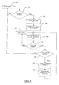
FIG. 2 shows a block diagram of the operation of an electronic control unit of the system ofFIG. 1 ; -
FIG. 3 shows a block diagram of the operation of a driving unit of the system ofFIG. 1 ; -
FIG. 4 shows a memory structure of the system ofFIG. 1 ; -
FIG. 5 shows a block diagram of operation for adjusting time variables in the system ofFIG. 1 ; -
FIGs. 6 and 7 show examples of interfaces for adjusting time variables in the system ofFIG. 1 ; and -
FIG. 8 shows a block diagram of operation for selecting time variables in the system ofFIG. 1 . - With reference to
fig. 1 , a bicycleelectronic system 1 according to an embodiment of the invention generally comprises anelectronic control unit 2, at least oneactuator 3 associated with a chain guide element or derailleur intended to move a chain for transmitting motion among toothed wheels associated with the crank axle and/or with the hub of the rear wheel of the bicycle, and adriving unit 4 of the actuator(s) 3. - Said at least one
actuator 3 can for example comprise an electric motor, preferably a stepper motor, coupled with an articulated parallelogram, but other types of motor or other types of actuator well known in the art can be used, for example a rack and pinion system or a worm gear system, for example the one described inU.S. 6,679,797 , herein incorporated by reference. - The bicycle
electronic system 1 preferably further comprises at least oneposition transducer 5 suitable for detecting the position of theactuator 3 and therefore indirectly of the derailleur, or for directly detecting the position of the derailleur, to cooperate with the drivingunit 4 and/or with theactuator 3 itself in moving the derailleur. - In the bicycle
electronic system 1, theelectronic control unit 2 has a plurality ofswitches 6 of the normally open type associated therewith, actuated by the cyclist through levers or buttons to input manual gearshifting requests and/or one ormore sensors 7 of travel parameters, such as travel speed, cranks rotation speed, slope of the travel ground, cyclist's heart rate and similar, from which theelectronic control unit 2 derives a desired gear ratio and therefore the advisability of carrying out a gearshifting. Thesensors 7, where provided for, are preferably under the control of a secondelectronic control unit 11, which can provide for pre-processing their outputs. Alternatively, thesensors 7 could be under the direct control of theelectronic control unit 2 or even under the control of thedriving unit 4 or of the display unit 8. - The normally
open switches 6 can of course be replaced by normally closed switches or by selector switches. - The bicycle electronic system preferably further comprises a display unit 8 for providing the cyclist with information, with which further switches 9 are preferably associated, actuated by the cyclist through buttons or a multi-direction button (joystick) to select the type of data to be displayed and/or to input other parameters and/or commands, preferably by selecting areas of the display of the display unit 8 in the manner of a graphical user interface. Alternatively, the display unit 8 can be a touch screen. The display unit 8 can comprise its own logic unit suitable for managing the information displayed and for managing the communication with the other components of the system, in particular with the
electronic control unit 2. - The
electronic control unit 2 is preferably positioned close to the cyclist actuatable command members, namely close to the handlebars, in particular it can be housed in the casing of the display unit 8 fixed to the centre of the handlebars. - The driving
unit 4 is preferably positioned close to theactuators 3, for example close to a bottle-holder of the bicycle. - The
electronic control unit 2 and thedriving unit 4 communicate through acommunication channel 10. - Communication is preferably via cable, but alternatively communication can be a radio transmission (wireless).
- The display unit 8 and the second electronic control unit or
sensor unit 11, where provided for, also preferably communicate through the same communication channel and the same communication protocol. - More specifically, in the case of half duplex asynchronous serial communication, the communication channel in practice comprises two common signal lines "Tx/Rx" and "WU", to which the
electronic control unit 2 and thedriving unit 4, as well as the possibleother units 8, 11, are connected to form a communication network. - The signal line Tx/Rx is a receiver/transmitter line for a bi-directional transmission of the data between the
various components - When one of the
units units - The sender then transmits a packet of serial data on the transmission line Tx/Rx.
- Each data packet comprises one or more header bytes depending upon the communication protocol used, and one or more data bytes.
- There can also be data for checking the transmission, for example parity or check-sum bit(s).
- The header bytes comprise the indication of the instructions that must be carried out by the recipient, such information being defined in terms of a code that also encodes the recipient itself, as well as the address of the sender.
- The data bytes depend, in length, structure and content, upon which
unit unit - When the status line WU is taken to "0" by the sender, the
units unit other units - At the end of the transmission from the recipient to the sender, the sender takes the status line WU to "1" thus releasing the communication network. In the case in which none of the
units - The described half duplex asynchronous serial communication is a "random access multi-master communication system", where the exclusive use of the network is carried out by the first "sender"
unit - If more than one
unit various units - This occurs, for example, when two or
more units - As an alternative to the half duplex asynchronous serial communication described above, between the
units - The operation of the bicycle
electronic system 1 shall be described hereinafter with reference toFIGs. 2 and3 , which show block diagrams respectively relating to theelectronic control unit 2 and to thedriving unit 4. - In a
block 101, theelectronic control unit 2 establishes whether a gearshifting is necessary. In the case of exclusively manual operation of theelectronic system 1 or in the case of a manual operating mode, step 101 of establishing whether a gearshifting is necessary takes place through the detection of the switching of status, typically of the closing, of one of the normallyopen switches 6, caused by the actuation of the lever or button associated therewith. In the case of exclusively automatic operation of theelectronic system 1 or in the case of an automatic operating mode, step 101 of establishing whether a gearshifting is necessary takes place in a way that is well known per se in the art based upon the data detected through thesensors 7. For example, a gearshifting request can be generated based upon the bicycle speed detected by a speed sensor. In the case of exclusively semiautomatic operation of theelectronic system 1 or in the case of a semiautomatic operating mode, step 101 of establishing whether a gearshifting is necessary takes place both through detecting the switching of status, typically closing, of one of the normallyopen switches 6, and based upon the signals coming from thesensors 7. In the latter case, the fulfilment of a manual gearshifting request can be subordinated to checking the data detected through thesensors 7, or vice-versa a manual gearshifting request can take priority over the evaluation of the data detected through thesensors 7. - If in
block 101 theelectronic control unit 2 establishes that a gearshifting is not necessary, it passes to performing other functions - block 102 -, for example to management of errors, to communication with the display unit 8, to reading the signals coming from thesensors 7 through the secondelectronic control unit 11 etc. It is worthwhile highlighting that the shown sequential nature betweenblocks electronic system 1, the positive check ofblock 101 can for example consist of an interrupt generated at the switching of status of theswitch 6. - If, on the other hand, in
block 101 theelectronic control unit 2 establishes that a gearshifting is necessary, which as shall become clear hereinafter can be a first single gearshifting of a multiple gearshifting, in ablock 103 theelectronic control unit 2 generates a data packet P1 -block 103 - and transmits it to thedriving unit 4 on the communication channel 10 -block 104. The transmission of the data packet P1 can optionally be repeated cyclically - block 105 -, for example every 50 ms. More generally, the repetition interval can be between 10 ms and 120 ms, preferably between 30 ms and 70 ms. - In the header byte(s) of the data packet P1, the gearshifting request and the type of gearshifting are encoded - i.e. whether it is an upward or downward gearshifting and whether it refers to the front or rear derailleur where they are both present. The data byte(s) of the data packet P1 contain (s) a time value T, which meaning shall become clear hereinafter.
- With reference to
FIG. 3 , the drivingunit 4 monitors the receipt of the data packet P1 - block 201 -, performing other functions - block 202 -, for example checking the signals coming from the transducer(s) 5, indicative of possible undesired movements of the actuator, until receipt of the data packet P1. - When the driving
unit 4 receives the data packet P1 - block 201 -, it decodes the information encoded therein - block 203 -, taking out the time value T. - In an embodiment, the time value T contained in the data byte(s) of the data packet P1 is a desired waiting time T1 that the driving
unit 4 must let lapse without carrying out the single gearshifting. During the course of a multiple gearshifting, the waiting time T1 lapses, as shall be understood, between the completion of a single gearshifting and the start of another single gearshifting. - In another embodiment, the time value T contained in the data byte(s) of the data packet P1 is a desired total time to carry out the single gearshifting, in other words, during the course of a multiple gearshifting, the desired total time between the completion of a single gearshifting and the completion of another single gearshifting.
- In the case of this second embodiment, the driving
unit 4 knows the estimated time Ts to carry out a single gearshifting, for example stored in a memory location, and calculates - block 204 - a waiting time T1 as the difference between the time value T decoded by the data packet P1 and the estimated time Ts to carry out a single gearshifting. The estimated time Ts to carry out a single gearshifting can be fixed or calculated by the drivingunit 4 itself based upon the times taken to carry out the previous gearshiftings - for example a moving average. - In both embodiments, the driving
unit 4 therefore waits - block 205 - for a time equal to the waiting time T1, decoded or calculated, respectively. - After the waiting time T1, the driving
unit 4 actuates -blocks 206, 207 - the single upward or downward gearshifting, of the front or rear derailleur, in accordance with what has been decoded from the header byte(s) of the data packet P1. - More specifically, according to the block diagram of
FIG. 3 , to carry out the gearshifting the drivingunit 4 sends - block 206 - a driving signal, in one direction or in the opposite one, to the front orrear actuator 3 until it checks - block 207- that the position of the derailleur -or the position of theactuator 3 and therefore indirectly of the derailleur-, detected through theposition transducer 5, corresponds with the desired destination position, in other words at the immediately adjacent toothed wheel. - In another embodiment, the driving of the
actuator 3 can take place with the sending of a driving signal of predetermined magnitude or duration, thereafter checking the position of theactuator 3 detected by theposition transducer 5 and possibly generating a further driving signal of theactuator 3 in case a correction of the position of theactuator 3 and therefore indirectly of the derailleur is necessary. - In yet another embodiment, wherein the
electronic system 1 lackstransducers 5, the driving of theactuator 3 can take place simply with the sending of a driving signal of predetermined magnitude or duration, without any check that theactuator 3 and therefore indirectly the derailleur have actually reached the desired position. - It should be noted that the estimated time Ts can in particular coincide with the powering time of the
derailleur 3 duringstep 206. - Once the single gearshifting is complete - output yes from block 207 -, the driving
unit 4 immediately generates and sends on the communication channel a data packet Ack for theelectronic control unit 2, encoding the completion of the single gearshifting -block 208. - Going back to
FIG. 2 , theelectronic control unit 2 receives - block 106 - this data packet Ack and therefore detects the completion of the single gearshifting. - With a
block 107 it is indicated that theelectronic control unit 2 performs other functions until receipt of the data packet Ack - output yes ofblock 106, including the possible repeated sending of the data packet P1 -block 105. The shown sequential nature among blocks 105-107 is also purely illustrative: in an event-driven embodiment of theelectronic system 1, the positive check ofblock 106 can for example consist of an interrupt. - As soon as the
electronic control unit 2 detects the completion of the single gearshifting - output yes from block 106 -, in ablock 108 it establishes whether a further gearshifting is necessary, totally analogously to what has been described above with reference to block 101. More specifically, in the case of manual operation or operating mode, step 108 of establishing whether a further gearshifting is necessary takes place through detecting that the status of theswitch 6 still corresponds with the gearshifting request, for example because the cyclist is exerting a prolonged pressure on the lever or button associated with theswitch 6, or he/she has pressed it a second time in quick succession after the first time. In the case of automatic or semiautomatic operation or operating mode of theelectronic system 1 or in the case of an automatic operating mode, theelectronic control unit 2 will have established - beforehand inblock 101 or during the performance of the other functions in block 107 - whether a single gearshifting was necessary, and therefore the check ofblock 108 shall have a negative outcome, or a multiple gearshifting was necessary, and therefore the check ofblock 108 shall have a positive outcome. - If the check of
block 108 has a negative outcome, the single gearshifting has ended and theelectronic control unit 2 goes back to performing its functions -blocks 101 and 102 -, including monitoring the manual gearshifting requests and/or evaluating the advisability of changing the gear ratio. - If, on the other hand, the check of
block 108 has a positive outcome, it is a multiple gearshifting and therefore at least one further single gearshifting is necessary. In this case, theelectronic control unit 2 generates a data packet P2 - block 109 - and transmits it to the driving unit 4 -block 110. The data packet P2 is analogous to the data packet P1 generated inblock 103, but it encodes a time value T preferably larger than the data packet P1. - The behaviour of the
driving unit 4 totally corresponds to what has been described relative to the data packet P1. - When the driving
unit 4 receives the data packet P2 - block 201 - or the first of the data packets P2 in the case of a multiple sending, it decodes it - block 203 -, taking out the time value T. - Similarly to the data packet P1, the time value T contained in the data byte(s) of the data packet P2 is a desired waiting time T2 between the completion of a single gearshifting and the start of another single gearshifting during the course of a multiple gearshifting, or a desired total time between the completion of one single gearshifting and the completion of another single gearshifting during the course of a multiple gearshifting.
- The driving
unit 4 thus waits - block 205 - for a time equal to the waiting time T2 decoded from the data packet P2, or calculated inblock 204 as the difference between the time value T decoded from the data packet P2 and the estimated time Ts to carry out a single gearshifting. - After the waiting time T2, the driving
unit 4 actuates -blocks 206, 207 - the single upward or downward gearshifting, of the front or rear derailleur, in accordance with what has been decoded from the header byte(s) of the data packet P2. - Once the second single gearshifting is complete - output yes from block 207-, the driving
unit 4 immediately generates and sends on the communication channel a second data packet Ack for theelectronic control unit 2, encoding the completion of the single gearshifting -block 208. - As soon as the
electronic control unit 2 detects the completion of the second single gearshifting - block 106 -, inblock 108 it establishes whether a further (third) gearshifting is necessary as described above. If the check ofblock 108 has a negative outcome, the multiple gearshifting (double gearshifting) has ended and theelectronic control unit 2 goes back to performing its own functions - blocks 101 and 102. - If, on the other hand, the check of
block 108 has a positive outcome, it is at least a triple gearshifting and theelectronic control unit 2 generates a data packet P3 - block 109 - and transmits it to the driving unit 4 - block 110 -, which processes it in a manner totally corresponding to what described relative to the data packets P1 and P2. The above described operating cycle is repeated until completion of the multiple gearshifting. - The data packet P3,... is analogous to the data packets P1 and P2 and encodes a time value T preferably larger than the data packet P1, not necessarily distinct from the time value encoded in the data packet P2.
- With the method described above, before starting each successive single gearshifting of a multiple gearshifting, with the movement of the
actuator 3 of the derailleur, a waiting time T2, T3, ... is introduced by the drivingunit 4. During such a waiting time T2, T3, ..., theactuator 3 is still and the chain manages to engage the toothed wheel and to ensure a secure gearshifting before it is moved for a subsequent single gearshifting of a multiple gearshifting. The waiting time T1 introduced before the first single gearshifting, on the other hand, is preferably minimized, possibly even equal to zero, in which case no actual delay is introduced. Indeed, the bicycleelectronic system 1 is desired to immediately react to the first actuation of the gearshifting lever or button by the cyclist, or as soon as theelectronic control unit 2 considers it advisable. - It should be noted that the optional multiple sending of the data packet P1, P2 (, P3...) by the electronic control unit 2 - block 105- can allow the frequency of check of the communication channel by the driving
unit 4 and the possible communication errors to be reduced, especially in the case of wireless communication. In any case, the drivingunit 4 processes just one of the data packets P1, P2.... Indeed, block 201 is again carried out only after the data packet Ack of successful gearshifting has been sent, as a consequence of which theelectronic control unit 2 stops sending the data packet P1, possibly sending the data packet P2 (P3,...). - In order to further reduce the risk of the
driving unit 4 processing the same data packet P1, P2 (, P3...) twice, it is also possible to consider that the time values T encoded in distinct data packets never coincide, for example increasing the time value T in each new data packet generated by theelectronic control unit 2 even only by one millisecond. In this case, the drivingunit 4 shall ignore data packets in which there is a time value T identical to that of the data packet just processed. - To the same purpose, alternatively it can be provided to associate a unique identifier, or a reference to the starting or destination toothed wheel, with each data packet P1, P2 (, P3...). In the case of a rear gearshift group with eleven toothed wheels, for example, four bits could be sufficient to encode the toothed wheel.
- The waiting time values T1, T2, T3,... and therefore the time values T transmitted in each data packet P1, P2, P3... are suitably selected.
- For example, the waiting time T1 introduced before the first single gearshifting can be selected as 0 ms as stated above, or 10 ms and therefore the time value T transmitted in the first data packet P1 can be 0 ms or 10 ms, respectively, in case it represents the desired time between the completion of a single gearshifting and the start of another single gearshifting during the course of a multiple gearshifting and the calculation step of
block 204 is not carried out, or T can for example be 200 ms or 210 ms, respectively, in case it represents the desired total time between the completion of a single gearshifting and the completion of another single gearshifting during the course of a multiple gearshifting and thecalculation step 204 is carried out, assuming an estimated time Ts to carry out a single gearshifting of 200 ms. The waiting time T2 introduced before the second single gearshifting can be selected for example as 300 ms and therefore the time value T transmitted in the second data packet P2 can be 300 ms in the absence ofcalculation step 204, or 500 ms in the presence ofcalculation step 204. The waiting time T3,... introduced before the further single gearshiftings can be selected, as stated above, equal to the waiting time T2 introduced before the second single gearshifting, namely 300 ms, or slightly above, even just equal to 301 ms, ... and therefore the time value T transmitted in the third, ... data packet P3, ... can be 300 ms or 301, ... ms in the absence of thecalculation step 204, or 500 ms or 501, ... ms in the presence of thecalculation step 204. - More generally, the waiting time T1 can be comprised between 0 ms and 50 ms, more preferably between 0 and 10 ms.
- The waiting time(s) T2, T3,... can be comprised between 50 and 500 ms, more preferably between 200 and 400 ms.
- The estimated time Ts to carry out a single gearshifting depends upon the type of
actuator 3 and upon its control. The value of 200 ms used in the above examples is purely indicative. In the case of the front actuator, the estimated time Ts can for example be about 350ms, in the case of the rear actuator for example about 100ms. As stated above, moreover, the estimated time Ts can be adjusted updating it based upon the real times of the previously carried out gearshiftings. - In another embodiment, waiting
step 205 by the drivingunit 4 for a waiting time T1, T2, T3, ... can be carried out after thedriving unit 4 has detected that the single gearshifting is complete - output yes from block 207 - and before generating and transmitting the data packet Ack indicative thereof -block 208. - Waiting
step 205 by the drivingunit 4 for a waiting time T1, T2, T3, ... can also be carried out after thedriving unit 4 has generated and transmitted the data packet Ack. In this case, if thedriving unit 4 receives a further data packet P2, P3,... during the waiting time T1, T2, T3..., it will suspend its processing until the end of the waiting time T1, T2, T3... itself. - In the case of waiting after the actuation of the gearshifting, the waiting time T1 associated with the first single gearshifting is also selected of a suitable not null value, possibly equal to the next waiting time(s) T2, T3, ..., to allow the secure engagement of the chain on the immediately adjacent toothed wheel, where it is immediately taken upon receipt of the first data packet P1.
- In the case of a single gearshifting, the imposition of a waiting time T1 by the electronic control unit 2 - through the transmission of the waiting time T1 or of the total time T corresponding to the sum of the waiting time T1 and of the estimated time Ts to carry out a gearshifting - allows the sending of the gearshifting request to the
driving unit 4 to be advanced, thus freeing theelectronic control unit 2 earlier. For example, theelectronic control unit 2, in the case of exclusively automatic operation or in an automatic operating mode, could establish that the bicycle is accelerating considering it advisable to gearshift in a short time, but not immediately, and allocate to thedriving unit 4 the time waiting prior to gearshifting (for example a few seconds). Again as an example, in the case of exclusively semiautomatic operation or in a semiautomatic operating mode, theelectronic control unit 2 could establish that it is advisable to delay the actuation of a gearshifting request by the cyclist, to actuate it at an optimal speed calculated based upon the instantaneous acceleration at the moment of the manual request; also in this case theelectronic control unit 2 can allocate to thedriving unit 4 the time waiting prior to gearshifting. - Even more generally, the
electronic control unit 2 could transmit to the driving unit 4 a request to carry out a gearshifting within the total time indicated by the time value T, the choice of the moment when to begin gearshifting, lasting substantially as the estimated time Ts to carry out a gearshifting, during such a time interval T being allocated to thedriving unit 4, which in this case could also carry out two distinct waits, one before and one after the actuation of the gearshifting. - Therefore, it is worthwhile highlighting that the transmission of the time value T associated with the gearshifting request is also advantageous irrespective of the provision of multiple gearshiftings, namely even in the absence of the blocks 107-110 of
FIG. 2 . - The various time values considered in the bicycle
electronic system 1 namely the waiting times T2, T3, ... and possibly T1 directly transmitted as time value T in the absence ofcalculation step 204, or the time values T transmitted and/or the estimated time Ts to carry out a single gearshifting in the presence of thecalculation step 204, can be a function of the direction of gearshifting, of the derailleur, of the specific starting toothed wheel and/or of the specific destination toothed wheel. - In these cases, the
electronic control unit 2 will each time transmit to the driving unit 4 a suitable time value T, according to the specific gearshifting operation. - Moreover, the various time values considered in the bicycle
electronic system 1, namely the waiting times T2, T3, ... and possibly T1 directly transmitted as time value T in the absence of thecalculation step 204, or the time values T transmitted and/or the estimated time Ts to carry out a single gearshifting in the presence of thecalculation step 204, can be adjusted to take the preferences of the cyclist and mechanical variations of the bicycle transmission system, for example because of replacements of parts after wear or damage, into account. - The waiting time T1 possibly provided for before the first single gearshifting of a multiple gearshifting, namely when the waiting by the driving
unit 4 takes place before the gearshifting is carried out, preferably cannot however be modified, since as stated above it is suitable for it to keep a low or zero value to maximize the speed of response of the bicycleelectronic system 1. - In order to allow such adjustment(s), the bicycle
electronic system 1 can comprise, as shown inFIG. 4 , astatic memory 12, for example a flash memory, and avolatile memory 13, for example a RAM memory, internal to theelectronic control unit 2, and astatic memory 14, for example anEEPROM memory 13, external to theelectronic control unit 2. In the case in which the estimated time Ts to carry out a single gearshifting is also adjustable, the drivingunit 4 can have a similar memory structure or it can receive the value of the estimated time Ts or its default value in the case of adjustment based upon the real time of the previous gearshiftings, from theelectronic control unit 2 through thecommunication channel 10. - In the
static memory 12 the various default time values are stored at factory. In thevolatile memory 13 the time values to be used to generate the data packets P1, P2 (P3,...) during the use of theelectronic system 1 are stored. In thestatic memory 14 the default time values are stored at the moment when it leaves the factory, and thereafter the time values set by the user as described hereinafter. - The adjustment of the time values takes place for example as described hereinafter with reference to
FIG. 5 . - The
electronic system 1 for a bicycle displays - block 301- on the display unit 8, for example after one of thebuttons 9 associated therewith has been pressed, a setting page of one of the time values, for example the waiting time T2 or a waiting time in the case of upward gearshifting or a waiting time in the case of downward gearshifting, and allows the user to adjust its value - block 302- through thebuttons 9 associated with the display unit 8 or through other manual command members, for example the manual command members associated with theswitches 6 and managed in a context sensitive manner, or one or more buttons provided on the command device carrying the manual command members associated with theswitches 6, or also by pressing areas of a touch screen of the display unit 8. Hereinafter, exclusive reference to thebuttons 9 associated with the display unit 8 will be made for the sake of brevity. - For example, the displayed page can have the appearance shown in
FIG. 6 , wherein the type of value being adjusted is shown in atitle 20 and its current value is shown in acentral area 21, initially read from thevolatile memory 13, as well as two increase and decreaseicons 22 cooperating with two of thebuttons 9 associated with the display unit 8 to form a graphical user interface. - Pressing the
buttons 9 allows the value displayed in thecentral area 21 and stored in thevolatile memory 13 to be respectively increased or decreased -block 302 ofFIG. 5 . - Preferably, each time the
buttons 9 are pressed corresponds to a small change in the value displayed in thecentral area 21, for example by an absolute value of 2 ms. In this way it is possible for the user to perform a fine adjustment of the time value. - Preferably, a minimum value, for example 50 ms, and a maximum value, for example 500 ms, can also be provided for in the case of adjustment of the waiting time T2 (T3,...) associated with the second (third,...) single gearshifting.
- In an alternative, the time value can be selected between a predetermined number of alternatives, for example three. In the case of adjustment of the waiting time T2 (T3,...) associated with the second (third,...) single gearshifting, for example, a first value equal to 500 ms, corresponding to a low multiple gearshifting speed, a second value equal to 350 ms, corresponding to a medium multiple gearshifting speed, or a third value equal to 50 ms, corresponding to a high multiple gearshifting speed can be provided for.
- The displayed page can have the appearance shown in
FIG. 7 , wherein in thecentral area 21 three bars of different heights are displayed, which could be replaced bynumbers - The
buttons 9 associated with the display unit 8 allow the waiting time to be increased or decreased, in accordance with theicons 22, which could however be left out. A single button can also be used, the current selection cyclically passing among the three - or more - displayed alternatives. The current selection can be highlighted for example through the movement of a cursor 23 among the displayed alternatives, making the current selection flash or change colour or background, displaying only the icon relating to the current selection, etc. - Still alternatively, the adjustment can be carried out in terms of multiple gearshifting speed, which stands in an inverse relationship with the waiting time(s), the bicycle
electronic system 1 taking care of converting the desired multiple gearshifting speed in terms of waiting time(s). - Going back to
FIG. 5 , once the user is satisfied with the adjustment that has been made, for example upon pressure of one of thebuttons 9 associated with the display unit 8, the bicycleelectronic system 1 offers the user, for example through a suitable graphical interface made with the display unit 8 and thebuttons 9 associated therewith, the possibility of selecting among three alternatives - block 303. - A first alternative consists of saving the time value modified during the adjustment of
steps volatile memory 13 is copied into the external static memory 14 -block 304. - A second alternative consists of not saving the time value modified during the adjustment of
steps static memory 14 during the course of a previous adjustment - or when the system is switched on for the first time upon leaving the factory if adjustments have never been made - is copied in the volatile memory 13 -block 305. - A third alternative consists of not saving and reloading the default values, also deleting the previous adjustments. In this case, the value stored in the internal
static memory 12 is copied both into thevolatile memory 13 and into the external static memory 14 -block 306. - The cyclist could also be allowed to test the new adjustment stored in the
volatile memory 13, preserving his/her adjustment previously stored in the externalstatic memory 14, in other words a further alternative upon selection of which none of the blocks 304-306 is carried out. - Irrespectively of the selected alternative, the current value of the
volatile memory 13 can later be sent to the other units of the bicycleelectronic system 1, through the communication channel 10 -block 307, in particular to the display unit 8 and to thedriving unit 4, for example in the case of adjustment of the value of the estimated time Ts to carry out a single gearshifting. - It should be understood that in the case of adjustment of several time values it can be provided for that the selection of whether to save, not to save or return to the default values -blocks 303-306 - to take place after adjustment -
steps 301 and 302 - of each time value or of all of the time values. - The adjustment carried out by the user and stored in the external
static memory 14 is preserved by the bicycleelectronic system 1 also in case it is switched off, as is the default adjustment stored in the internalstatic memory 12. On the other hand, the time value (s) to be currently used are present in thevolatile memory 13 only when the bicycleelectronic system 1 is powered. - When the bicycle
electronic system 1 is switched on -block 401 ofFIG. 8 -, the default value(s) contained in the internalstatic memory 12 is/are copied in the volatile memory 13 -block 402. - The bicycle
electronic system 1 therefore offers the user the possibility of selecting between two alternatives - block 403-, for example through a suitable graphical interface made analogously to what has been described above. - A first alternative consists of using the default value(s). In this case, the value(s) stored in the internal static memory 12 (and in the volatile memory 13) is/are copied in the external static memory 14 -
block 404. - A second alternative consists of using the value(s) previously stored by the user. In this case, the value(s) stored in the external
static memory 14 is/are copied in the volatile memory 13 -block 405, leaving the default value(s) present in the internalstatic memory 12 unmodified. - Irrespectively of the selected alternative, the current value(s) of the
volatile memory 13 can later be sent to the other units of the bicycleelectronic system 1, through the communication channel 10 - block 307 -, in particular to the display unit 8 and to thedriving unit 4, for example in the case of adjustment of the value of the estimated time Ts to carry out a single gearshifting. - The copy from the internal
static memory 12 to the external static memory 14 - block 404 - could be left out, therefore preserving a previous user adjustment for the possible use when theelectronic system 1 for a bicycle is switched on at a later time. - According to an alternative operating mode, when the bicycle
electronic system 1 is switched on it could directly propose the alternative of whether to use the default value(s) or the value(s) stored previously by the user, copying in thevolatile memory 13 the value of the internalstatic memory 12 or of the externalstatic memory 14, respectively. - Furthermore, it should be understood that the data packets P1, P2, P3... transmitted from the
electronic control unit 2 to thedriving unit 4 could lack the indication of the waiting time, the duration of the waiting time T1, T2, T3... being defined in thedriving unit 4 itself. In this case, if the wait - block 205 - is carried out before the actuation of each single gearshifting -blocks 206, 207-, it is suitable to indicate in the data packet P1 the fact that it is a single gearshifting or the first single gearshifting of a multiple gearshifting, so that the drivingunit 4 can wait a shorter time with respect to the subsequent gearshiftings to preserve the desired speed of response. - Even more generally, the division of a multiple gearshifting request into at least two single gearshiftings with the interposition of the wait could also be entirely managed within the driving
unit 4, theelectronic control unit 2 in this case transmitting a multiple gearshifting request, for example a data packet wherein the destination toothed wheel or the number of single gearshiftings to be carried out is identified. - Finally, it should be understood that the possibility of adjusting the waiting times T1, T2, T3,... can also be advantageous when the wait takes place in the
electronic control unit 2 instead of in thedriving unit 4 or when there is a single electronic control and driving unit.
Claims (99)
- Method for carrying out a multiple gearshifting in a bicycle gearshift, comprising the steps, repeated at least twice, of:a) transmitting (103, 104) a single gearshifting request (P1, P2, P3,...) from an electronic control unit (2),b) receiving (201) said single gearshifting request in a driving unit (4),c) moving (206, 207) a chain of the gearshift between two adjacent toothed wheels through said driving unit (4) to carry out a single gearshifting,
and the step, carried out between two executions of step c), of:d) deliberately waiting (205) for a waiting time (T1, T2, T3, ...),characterized in that said waiting step d) is carried out in said driving unit (4). - Method according to claim 1, further comprising the step of:e) transmitting (208) a successful single gearshifting signal (Ack) from the driving unit (4) to the electronic control unit (2).
- Method according to any of the previous claims, wherein step d) of waiting for a waiting time (T1, T2, T3,...) is also carried out before the first execution of step c) of moving (206, 207) the chain.
- Method according to any of the previous claims, wherein step a) of transmitting (103, 104) a single gearshifting request comprises transmitting a data packet (P1, P2, P3,...) containing a time value (T) indicative of the waiting time (T1, T2, T3, ...) from the electronic control unit (2) to the driving unit (4).
- Method according to any of the previous claims, wherein transmission step a) takes place through a communication channel via cable.
- Method according to any of the previous claims, wherein transmission step a) takes place through a half duplex asynchronous serial communication protocol.
- Method according to any of claims 4-6, wherein the data packet (P1, P2, P3,...) is transmitted (105) at least a second time.
- Method according to any of claims 4-7, wherein the data packet (P1, P2, P3,...) is transmitted (105) with a predetermined repetition frequency until receipt of said successful single gearshifting signal (Ack).
- Method according to any of claims 4-9, wherein the time value (T) indicative of the waiting time (T1, T2, T3,...) coincides with the waiting time (T1, T2, T3,...).
- Method according to claims 4-9, wherein the time value (T) indicative of the waiting time (T1, T2, T3,...) is a desired total time to complete a single gearshifting, the step of:f) calculating (204), in the driving unit (4), the waiting time (T1, T2, T3,...) by subtracting an estimated time (Ts) to carry out a single gearshifting from the time value (T) indicative of the waiting time (T1, T2, T3,...)being provided.
- Method according to claim 10, wherein the estimated time (Ts) to carry out a single gearshifting is variable.
- Method according to any of claims 2-11, wherein step e) of transmitting (208) a successful single gearshifting signal (Ack) takes place through a communication channel via cable.
- Method according to any of claims 2-12, wherein step e) of transmitting (208) a successful single gearshifting signal (Ack) takes place through a half duplex asynchronous serial communication protocol.
- Method according to any of the previous claims, wherein step a) is carried out as a consequence of a step of:g) receiving a manual gearshifting request (6) from the user.
- Method according to any of the previous claims, comprising the step ofh) detecting (7) travel parameters and generating said gearshifting request (P1, P2, P3,...) based upon the detected travel parameters.
- Method according to any of the previous claims, wherein the waiting time (T1, T2, T3,...) is comprised between 0 ms and 500 ms.
- Method according to any of claims 3-16, wherein the waiting time (T1) waited in step d) carried out before the first execution of step c) is comprised between 0 ms and 50 ms.
- Method according to any of the previous claims, wherein the waiting time (T2, T3,...) waited in step d) associated with a single gearshifting following the first single gearshifting of a multiple gearshifting is comprised between 50 ms and 500 ms.
- Method according to any of the previous claims, wherein the waiting time (T1, T2, T3,...) associated with different single gearshiftings of a multiple gearshifting is different.
- Method according to any of the previous claims, wherein the waiting time (T1, T2, T3,...) is a function of the gearshifting direction, of the derailleur, of the specific starting toothed wheel and/or of the specific destination toothed wheel.
- Method according to any of the previous claims, further comprising the step of:i) manually adjusting (301, 302) at least one time value (T1, T2, T3,..., T) indicative of the waiting time (T1, T2, T3,...) and/or an estimated time (Ts) to carry out a single gearshifting.
- Method according to claim 21, wherein manual adjustment step i) comprises increasing or decreasing said at least one time value (T1, T2, T3,..., T) and/or said estimated time (Ts) to carry out a single gearshifting by a comparatively small amount at a time.
- Method according to claim 22, wherein a minimum value and/or a maximum value of said at least one time value (T1, T2, T3,..., T) and/or of said estimated time (Ts) to carry out a single gearshifting are provided in the manual adjustment step i).
- Method according to claim 21, wherein manual adjustment step i) comprises selecting between a predetermined number of alternatives of said at least one time value (T1, T2, T3,..., T) and/or of said estimated time (Ts) to carry out a single gearshifting.
- Method according to any of claims 21-24, further comprising a step, following said manual adjustment step i), of:j1) storing (304) for later use said at least one adjusted time value (T1, T2, T3,..., T) and/or said adjusted estimated time (Ts) to carry out a single gearshifting.
- Method according to any of claims 21-24, further comprising a step, following said manual adjustment step i), of:j2) returning (305) to a previously adjusted value of said at least one time value (T1, T2, T3,..., T) and/or of said estimated time (Ts) to carry out a single gearshifting.
- Method according to any of claims 21-24, further comprising a step, following said manual adjustment step i), of:j3) returning (306) to a default value of said at least one time value (T1, T2, T3,..., T) and/or of said estimated time (Ts) to carry out a single gearshifting.
- Method according to any of claims 21-27, further comprising the step of:k) selecting (402-405) for use a default value of said at least one time value (T1, T2, T3,..., T) and/or of said estimated time (Ts) to carry out a single gearshifting or a previously adjusted value of said at least one time value (T1, T2, T3,..., T) and/or of said estimated time (Ts) to carry out a single gearshifting.
- Method according to claim 28, wherein step k) of selecting for use is carried out upon switching the electronic system (1) on.
- Method according to any of claims 25-29, wherein one or more of said steps j1), j2), j3) and/or k) are carried out in said electronic control unit (2) and the method further comprises the step of:l) transmitting (307, 406) said default or adjusted, respectively, at least one time value (T1, T2, T3,..., T) and/or estimated time (Ts) to carry out a single gearshifting to other units (4, 8, 11) of the electronic system (1).
- Bicycle electronic system (1), comprising:- an electronic control unit (2) configured to transmit (103, 104) at least two single gearshifting requests (P1, P2, P3,...) to carry out a multiple gearshifting,- a driving unit (4) configured to receive (201) said at least two single gearshifting requests (P1, P2, P3,...) and to move (206, 207) a gearshift chain between two adjacent toothed wheels to carry out a single gearshifting as a consequence of having received each single gearshifting request (P1, P2, P3),characterized in that said driving unit is configured to deliberately wait (205) for a waiting time (T1, T2, T3,...) between movements (206, 207) of the chain as a consequence of having received successive single gearshifting requests (P1, P2, P3) of a multiple gearshifting.
- System (1) according to claim 31, further comprising at least one actuator (3) associated with a chain guide element intended to move a chain for transmitting motion among toothed wheels associated with the crank axle and/or with the hub of the rear wheel of the bicycle, said driving unit (4) being configured to drive said at least one actuator (3).
- System (1) according to claim 32, wherein said at least one actuator (3) comprises an electric motor coupled with an articulated parallelogram.
- System (1) according to any of claims 31-33, further comprising at least one position transducer (5) and wherein said driving unit (4) is configured to transmit (208) a successful single gearshifting signal (Ack) to the electronic control unit (2) when said at least one position transducer (5) indicates that the chain is at a destination toothed wheel of said adjacent toothed wheels.
- System (1) according to any of claims 31-34, wherein the driving unit (4) is further configured to wait for the waiting time (T1, T2, T3,...) prior to the movement (206, 207) of the chain.
- System (1) according to any of claims 31-35, wherein said electronic control unit (2) is configured to transmit (103, 104) the gearshifting request through a data packet (P1, P2, P3,...) containing a time value (T) indicative of the waiting time (T1, T2, T3, ...).
- System (1) according to any of claims 31-36, further comprising a communication channel via cable between the electronic control unit (2) and the driving unit (4).
- System (1) according to any of claims 31-37, wherein the electronic control unit (2) and the driving unit (4) communicate through a half duplex asynchronous serial communication protocol.
- System (1) according to any of claims 36-38, wherein the electronic control unit (2) is configured to transmit (105) the data packet (P1, P2, P3,...) at least a second time.
- System (1) according to any of claims 36-39, wherein the electronic control unit (2) is configured to transmit (105) the data packet (P1, P2, P3,...) with a predetermined repetition frequency until receipt of said successful single gearshifting signal (Ack).
- System (1) according to any of claims 36-40, wherein the time value (T) indicative of the waiting time (T1, T2, T3,...) coincides with the waiting time (T1, T2, T3,...).
- System (1) according to any of claims 36-40, wherein the time value (T) indicative of the waiting time (T1, T2, T3,...) is a desired total time to complete a single gearshifting, the driving unit (4) being configured to calculate (204) the waiting time (T1, T2, T3,...) by subtraction of an estimated time (Ts) to carry out a single gearshifting from the time value (T).
- System (1) according to claim 42, wherein said driving unit (4) comprises means for calculating the value of said estimated time (Ts) to carry out single gearshifting.
- System (1) according to any of claims 31-43, further comprising manual actuation members (6) for causing the transmission of said single gearshifting request (P1, P2, P3,...).
- System (1) according to any of claims 31-44, further comprising travel parameter sensors (7), wherein said electronic control unit (2) generates said single gearshifting request (P1, P2, P3,...) based upon the outputs of said sensors (7).
- System (1) according to any of claims 31-45, further comprising a user interface (8, 9, 6).
- System (1) according to claim 46, wherein the interface (8, 9, 6) is configured for manual adjustment (301, 302) of at least one time value (T1, T2, T3,..., T) indicative of the waiting time (T1, T2, T3,...) and/or of an estimated time (Ts) to carry out a single gearshifting.
- System (1) according to any of claims 46-47, wherein the interface (8, 9, 6) is configured to allow said at least one time value (T1, T2, T3,..., T) and/or said estimated time (Ts) to carry out a single gearshifting to be increased or decreased by a comparatively small amount at a time.
- System (1) according to claim 48, wherein the interface (8, 9, 6) is configured to set a minimum value and/or a maximum value of said at least one time value (T1, T2, T3,..., T) and/or of said estimated time (Ts) to carry out a single gearshifting.
- System (1) according to claim 47, wherein the interface (8, 9, 6) is configured to allow the selection between a predetermined number of alternatives of said at least one time value (T1, T2, T3,..., T) and/or of said estimated time (Ts) to carry out a single gearshifting.
- System (1) according to any of claims 47-50, further comprising a static memory (12) and a volatile memory (13) internal to the electronic control unit (2), and a static memory (14) external to the electronic control unit (2).
- System (1) according to claim 51, wherein said internal static memory (12) stores a default value of said at least one time value (T1, T2, T3,..., T) and/or of said estimated time (Ts) to carry out a single gearshifting.
- System (1) according to any of claims 51-52, wherein said internal static memory (12) is a flash memory.
- System (1) according to any of claims 51-53, wherein said volatile memory (13) stores a current value of said at least one time value (T1, T2, T3,..., T) and/or of said estimated time (Ts) to carry out a single gearshifting.
- System (1) according to any of claims 51-54, wherein said volatile memory (13) is a RAM memory.
- System (1) according to any of claims 51-55, wherein said external static memory (14) stores a value set by the user of said at least one time value (T1, T2, T3,..., T) and/or of said estimated time (Ts) to carry out a single gearshifting.
- System (1) according to any of claims 51-56, wherein said external static memory (14) is an EEPROM memory.
- System (1) according to any of claims 51-57, wherein the system (1) comprises selective copying means among said internal static memory (12), volatile memory (13) and external static memory (14).
- Method for electronically controlling a bicycle gearshift, comprising the steps of:a) transmitting (103, 104) a gearshifting request (P1, P2, P3,...) from an electronic control unit (2),b) receiving (201) said gearshifting request in a driving unit (4),c) moving (206, 207) a gearshift chain between two adjacent toothed wheels through said driving unit (4) to carry out said gearshifting, andd) deliberately waiting (205) for a waiting time (T1, T2, T3,...),
characterized in that said gearshifting request transmitted in step a) comprises a time value (T, T1, T2, T3,...) indicative of said waiting time (T1, T2, T3, ...), and said waiting step d) is carried out in said driving unit (4). - Method according to claim 59, further comprising the step of:e) transmitting (208) a successful single gearshifting signal (Ack) from the driving unit (4) to the electronic control unit (2).
- Method according to any of claims 59-60, wherein step d) of waiting for a waiting time (T1, T2, T3,...) is carried out before step c) of moving (206, 207) the chain.
- Method according to any of claims 59-61, wherein step a) of transmitting (103, 104) a single gearshifting request comprises transmitting a data packet (P1, P2, P3,...) containing the time value (T) indicative of the waiting time (T1, T2, T3, ...) from the electronic control unit (2) to the driving unit (4).
- Method according to claim 62, wherein the data packet (P1, P2, P3,...) is transmitted (105) at least a second time.
- Method according to any of claims 59-63, wherein the time value (T) indicative of the waiting time (T1, T2, T3,...) coincides with the waiting time (T1, T2, T3,...).
- Method according to any of claims 59-63, wherein the time value (T) indicative of the waiting time (T1, T2, T3,...) is a desired total time to complete a single gearshifting, the step of:f) calculating (204), in the driving unit (4), the waiting time (T1, T2, T3,...) by subtraction of an estimated time (Ts) to carry out a single gearshifting from the time value (T)being provided.
- Method according to claim 65, wherein the estimated time (Ts) to carry out a single gearshifting is variable.
- Bicycle electronic system (1), comprising:- an electronic control unit (2) configured to transmit (103, 104) a gearshifting request (P1, P2, P3,...),- a driving unit (4) configured to receive (201) said gearshifting request (P1, P2, P3,...) and move (206, 207) a gearshift chain between two adjacent toothed wheels to carry out said gearshifting,characterized in that said electronic control unit (2) is configured to transmit within said gearshifting request a time value (T, T1, T2, T3,...) indicative of said waiting time (T1, T2, T3, ...), and said driving unit is configured to deliberately wait (205) for said waiting time (T1, T2, T3,...).
- System (1) according to claim 67, further comprising at least one position transducer (5), and wherein said driving unit (4) is configured to transmit (208) a successful single gearshifting signal (Ack) to the electronic control unit (2) when said at least one position transducer (5) indicates that the chain is at a destination toothed wheel of said adjacent toothed wheels.
- System (1) according to any of claims 67-68, wherein the driving unit (4) is configured to wait for the waiting time (T1, T2, T3,...) before the movement (206, 207) of the chain.
- System (1) according to any of claims 67-69, wherein said electronic control unit (2) is configured to transmit (103, 104) the gearshifting request through a data packet (P1, P2, P3,...) containing a time value (T) indicative of the waiting time (T1, T2, T3, ...).
- System (1) according to claim 70, wherein the electronic control unit (2) is configured to transmit (105) the data packet (P1, P2, P3,...) at least a second time.
- System (1) according to any of claims 67-71, wherein the time value (T) indicative of the waiting time (T1, T2, T3,...) coincides with the waiting time (T1, T2, T3,...).
- System (1) according to any of claims 67-71, wherein the time value (T) indicative of the waiting time (T1, T2, T3,...) is a desired time to complete a single gearshifting, the driving unit (4) being configured to calculate (204) the waiting time (T1, T2, T3,...) by subtraction of an estimated time (Ts) to carry out a single gearshifting from the time value (T).
- System (1) according to claim 73, wherein said driving unit (4) comprises means for calculating the value of said estimated time (Ts) to carry out a single gearshifting.
- Method for carrying out a multiple gearshifting in a bicycle gearshift, comprising the step, repeated at least twice, of:a) moving (206, 207) a gearshift chain between two adjacent toothed wheels to carry out a single gearshifting,
and the step of:b) deliberately waiting (205) for a waiting time (T1, T2, T3,...) between two successive executions of step a),
characterized by further comprising the step of:c) manually adjusting (301, 302) at least one time value (T1, T2, T3,..., T) indicative of the waiting time (T1, T2, T3, ...) . - Method according to claim 75, characterized by further comprising the steps of:d) transmitting (103, 104) a single gearshifting request (P1, P2, P3,...) from an electronic control unit (2), ande) receiving (201) said single gearshifting request in a driving unit (4).
- Method according to any of claims 75-76, characterized in that moving step a) is carried out through said driving unit (4).
- Method according to any of claims 75-77, wherein manual adjustment step c) comprises increasing or decreasing said at least one time value (T1, T2, T3,..., T) by a comparatively small amount at a time.
- Method according to claim 78, wherein in the manual adjustment step c) a minimum value and/or a maximum value of said at least one time value (T1, T2, T3,..., T) are provided for.
- Method according to any of claims 75-77, wherein manual adjustment step c) comprises selecting between a predetermined number of alternatives of said at least one time value (T1, T2, T3,..., T).
- Method according to any of claims 75-80, further comprising a step, following said manual adjustment step c), of:f1) storing (304) for later use said at least one adjusted time value (T1, T2, T3,..., T).
- Method according to any of claims 75-80, further comprising a step, following said manual adjustment step c), of:f2) returning (305) to a previously adjusted value of said at least one time value (T1, T2, T3,..., T) and/or of said estimated time (Ts) to carry out a single gearshifting.
- Method according to any of claims 75-80, further comprising a step, following said manual adjustment step c), of:f3) returning (306) to a default value of said at least one time value (T1, T2, T3,..., T) and/or of said estimated time (Ts) to carry out a single gearshifting.
- Method according to any of claims 75-83, further comprising the step of:k) selecting (402-405) for use a default value of said at least one time value (T1, T2, T3,..., T) or a previously adjusted value of said at least one time value (T1, T2, T3,..., T).
- Method according to claim 84, wherein step k) of selecting for use is carried out upon switching the electronic system (1) on.
- Method according to any of claims 75-85, wherein one or more of said steps f1), f2), f3) and/or k) are carried out in said electronic control unit (2), and the method further comprises the step of:l) transmitting (307, 406) said default or adjusted, respectively, at least one time value (T1, T2, T3,..., T) to other units of the electronic system (1).
- Bicycle electronic system (1) configured to move (206, 207) a gearshift chain between two adjacent toothed wheels to carry out a single gearshifting, and comprising a user interface (8, 9, 6),
characterized in that the system (1) is configured to deliberately wait (205) for a waiting time (T1, T2, T3,...) between successive movements (206, 207) of a multiple gearshifting,
and in that the interface (8, 9) is configured for manual adjustment (301, 302) of at least one time value (T1, T2, T3,..., T) indicative of the waiting time (T1, T2, T3,...). - System (1) according to claim 87, comprising:- an electronic control unit (2) configured to transmit (103, 104) at least two single gearshifting requests (P1, P2, P3,...) to carry out a multiple gearshifting, and- a driving unit (4) configured to receive (201) said at least two single gearshifting requests (P1, P2, P3,...) and move (206, 207) said gearshift chain between two adjacent toothed wheels to carry out said single gearshifting.
- System (1) according to claim 88, wherein the interface (8, 9) is configured to allow said at least one time value (T1, T2, T3,..., T) to be increased or decreased by a comparatively small amount at a time.
- System (1) according to claim 89, wherein the interface (8, 9) is configured to set a minimum value and/or a maximum value of said at least one time value (T1, T2, T3,..., T).
- System (1) according to claim 88, wherein the interface (8, 9) is configured to allow the selection between a predetermined number of alternatives of said at least one time value (T1, T2, T3,..., T).
- System (1) according to any of claims 88-91, further comprising a static memory (12) and a volatile memory (13) internal to the electronic control unit (2), and a static memory (14) external to the electronic control unit (2).
- System (1) according to claim 92, wherein said internal static memory (12) stores a default value of said at least one time value (T1, T2, T3,..., T).
- System (1) according to any of claims 92-93, wherein said internal static memory (12) is a flash memory.
- System (1) according to any of claims 92-94, wherein said volatile memory (13) stores a current value of said at least one time value (T1, T2, T3,..., T) and/or of said estimated time (Ts) to carry out a single gearshifting.
- System (1) according to any of claims 92-95, wherein said volatile memory (13) is a RAM memory.
- System (1) according to any of claims 92-96, wherein said external static memory (14) stores a value set by the user of said at least one time value (T1, T2, T3,..., T) and/or of said estimated time (Ts) to carry out a single gearshifting.
- System (1) according to any of claims 92-97, wherein said external static memory (14) is an EEPROM memory.
- System (1) according to any of claims 92-98, wherein the system (1) comprises selective copying means among said internal static memory (12), volatile memory (13) and external static memory (14).
Applications Claiming Priority (1)
| Application Number | Priority Date | Filing Date | Title |
|---|---|---|---|
| IT001181A ITMI20071181A1 (en) | 2007-06-12 | 2007-06-12 | ELECTRONIC CONTROL METHOD OF A BICYCLE CHANGE AND ELECTRONIC BICYCLE SYSTEM |
Publications (3)
| Publication Number | Publication Date |
|---|---|
| EP2003051A2 true EP2003051A2 (en) | 2008-12-17 |
| EP2003051A3 EP2003051A3 (en) | 2009-06-03 |
| EP2003051B1 EP2003051B1 (en) | 2011-09-07 |
Family
ID=38656468
Family Applications (1)
| Application Number | Title | Priority Date | Filing Date |
|---|---|---|---|
| EP08005437A Not-in-force EP2003051B1 (en) | 2007-06-12 | 2008-03-22 | Method for electronically controlling a bicycle gearshift and bicycle electronic system |
Country Status (7)
| Country | Link |
|---|---|
| US (1) | US8874338B2 (en) |
| EP (1) | EP2003051B1 (en) |
| JP (1) | JP5406469B2 (en) |
| CN (1) | CN101327824B (en) |
| AT (1) | ATE523420T1 (en) |
| IT (1) | ITMI20071181A1 (en) |
| TW (1) | TWI450837B (en) |
Cited By (4)
| Publication number | Priority date | Publication date | Assignee | Title |
|---|---|---|---|---|
| EP2399813A1 (en) * | 2010-06-23 | 2011-12-28 | Shimano Inc. | Bicycle control system |
| ITMI20121279A1 (en) * | 2012-07-23 | 2014-01-24 | Campagnolo Srl | METHOD OF ELECTRONICALLY CHECKING A BICYCLE CHANGE AND ELECTRICALLY ASSISTED BICYCLE CHANGE |
| ITMI20121990A1 (en) * | 2012-11-22 | 2014-05-23 | Campagnolo Srl | METHOD OF ELECTRONICALLY CHECKING A BICYCLE CHANGE AND ELECTRICALLY ASSISTED BICYCLE CHANGE |
| ITVI20130114A1 (en) * | 2013-04-22 | 2014-10-23 | Franco Celli | VARIATOR OF REPORTS FOR BICYCLES. |
Families Citing this family (62)
| Publication number | Priority date | Publication date | Assignee | Title |
|---|---|---|---|---|
| ITMI20070140A1 (en) * | 2007-01-30 | 2008-07-31 | Campagnolo Srl | MAN-BICYCLE INTERACTION DEVICE |
| ITMI20070737A1 (en) * | 2007-04-12 | 2008-10-13 | Campagnolo Srl | EQUIPMENT AND ELECTRONIC SYSTEM FOR BICYCLE AND RELATIVE METHODS |
| ITMI20071181A1 (en) | 2007-06-12 | 2008-12-13 | Campagnolo Srl | ELECTRONIC CONTROL METHOD OF A BICYCLE CHANGE AND ELECTRONIC BICYCLE SYSTEM |
| ITMI20072407A1 (en) * | 2007-12-20 | 2009-06-21 | Campagnolo Srl | ELECTRONIC EQUIPMENT FOR BICYCLE |
| JP5046909B2 (en) * | 2007-12-21 | 2012-10-10 | 株式会社日本マイクロニクス | Contact for electrical test, electrical connection device using the contact, and method for manufacturing contact |
| EP2088071B1 (en) * | 2008-02-06 | 2013-12-11 | Campagnolo S.r.l. | Method for electronically controlling a bicycle gearshift and electronic system for a bicycle |
| US8627932B2 (en) | 2009-01-07 | 2014-01-14 | Fox Factory, Inc. | Bypass for a suspension damper |
| US20120305350A1 (en) | 2011-05-31 | 2012-12-06 | Ericksen Everet O | Methods and apparatus for position sensitive suspension damping |
| US10047817B2 (en) | 2009-01-07 | 2018-08-14 | Fox Factory, Inc. | Method and apparatus for an adjustable damper |
| US20100170760A1 (en) | 2009-01-07 | 2010-07-08 | John Marking | Remotely Operated Bypass for a Suspension Damper |
| US11306798B2 (en) | 2008-05-09 | 2022-04-19 | Fox Factory, Inc. | Position sensitive suspension damping with an active valve |
| US10060499B2 (en) | 2009-01-07 | 2018-08-28 | Fox Factory, Inc. | Method and apparatus for an adjustable damper |
| US9033122B2 (en) | 2009-01-07 | 2015-05-19 | Fox Factory, Inc. | Method and apparatus for an adjustable damper |
| US9452654B2 (en) | 2009-01-07 | 2016-09-27 | Fox Factory, Inc. | Method and apparatus for an adjustable damper |
| US8393446B2 (en) | 2008-08-25 | 2013-03-12 | David M Haugen | Methods and apparatus for suspension lock out and signal generation |
| US12491961B2 (en) * | 2008-11-25 | 2025-12-09 | Fox Factory, Inc. | Seat post |
| US10036443B2 (en) | 2009-03-19 | 2018-07-31 | Fox Factory, Inc. | Methods and apparatus for suspension adjustment |
| EP3666347B1 (en) | 2008-11-25 | 2021-10-20 | Fox Factory, Inc. | Computer usable storage medium for virtual competition |
| US9140325B2 (en) | 2009-03-19 | 2015-09-22 | Fox Factory, Inc. | Methods and apparatus for selective spring pre-load adjustment |
| US9422018B2 (en) | 2008-11-25 | 2016-08-23 | Fox Factory, Inc. | Seat post |
| US11299233B2 (en) | 2009-01-07 | 2022-04-12 | Fox Factory, Inc. | Method and apparatus for an adjustable damper |
| US12122205B2 (en) | 2009-01-07 | 2024-10-22 | Fox Factory, Inc. | Active valve for an internal bypass |
| US9038791B2 (en) | 2009-01-07 | 2015-05-26 | Fox Factory, Inc. | Compression isolator for a suspension damper |
| US8936139B2 (en) | 2009-03-19 | 2015-01-20 | Fox Factory, Inc. | Methods and apparatus for suspension adjustment |
| EP2312180B1 (en) | 2009-10-13 | 2019-09-18 | Fox Factory, Inc. | Apparatus for controlling a fluid damper |
| US8672106B2 (en) | 2009-10-13 | 2014-03-18 | Fox Factory, Inc. | Self-regulating suspension |
| US10697514B2 (en) | 2010-01-20 | 2020-06-30 | Fox Factory, Inc. | Remotely operated bypass for a suspension damper |
| EP3778358B1 (en) | 2010-07-02 | 2023-04-12 | Fox Factory, Inc. | Positive lock adjustable seat post |
| US9327792B2 (en) * | 2011-01-28 | 2016-05-03 | Paha Designs, Llc | Gear transmission and derailleur system |
| US10207772B2 (en) * | 2011-01-28 | 2019-02-19 | Paha Designs, Llc | Gear transmission and derailleur system |
| EP3567272B1 (en) | 2011-09-12 | 2021-05-26 | Fox Factory, Inc. | Methods and apparatus for suspension set up |
| TW201317161A (en) * | 2011-10-18 | 2013-05-01 | J D Components Co Ltd | Bicycle gear shift control system capable of avoiding frequent gear shifting |
| US11279199B2 (en) | 2012-01-25 | 2022-03-22 | Fox Factory, Inc. | Suspension damper with by-pass valves |
| EP4424574A1 (en) * | 2012-04-25 | 2024-09-04 | Fox Factory, Inc. | Seat post |
| US10330171B2 (en) | 2012-05-10 | 2019-06-25 | Fox Factory, Inc. | Method and apparatus for an adjustable damper |
| US8909424B2 (en) | 2012-10-11 | 2014-12-09 | Sram, Llc | Electronic shifting systems and methods |
| US9802669B2 (en) | 2012-10-11 | 2017-10-31 | Sram, Llc | Electronic shifting systems and methods |
| US9008923B2 (en) * | 2013-04-05 | 2015-04-14 | Shimano Inc. | Bicycle derailleur adjusting apparatus |
| ITMI20130895A1 (en) | 2013-05-31 | 2014-12-01 | Campagnolo Srl | ELECTRONIC BICYCLE SYSTEM |
| JP5869620B2 (en) * | 2014-05-23 | 2016-02-24 | 株式会社シマノ | Bicycle electric components |
| EP2979970B1 (en) * | 2014-08-01 | 2017-09-13 | Campagnolo S.R.L. | Bicycle electronic gearshift system and related method |
| DE102014111917A1 (en) * | 2014-08-20 | 2016-02-25 | Gustav Magenwirth Gmbh & Co. Kg | Hand-operated transmitter unit |
| US9278728B1 (en) * | 2014-10-29 | 2016-03-08 | Shimano Inc. | Bicycle shifting control apparatus and method of controlling derailleur |
| JP6305322B2 (en) * | 2014-11-28 | 2018-04-04 | 株式会社シマノ | Components and communication systems |
| US10370060B2 (en) * | 2015-10-30 | 2019-08-06 | Shimano Inc. | Bicycle electrical component assembly |
| CN106143772B (en) * | 2015-03-26 | 2019-04-09 | 久鼎金属实业股份有限公司 | Method for controlling stepless speed ratio of bicycle matched with planetary gear set |
| US9616964B2 (en) | 2015-04-27 | 2017-04-11 | Shimano Inc. | Bicycle wireless control system |
| US10457350B2 (en) | 2015-04-27 | 2019-10-29 | Shimano Inc. | Bicycle control system |
| JP6797188B2 (en) * | 2015-08-25 | 2020-12-09 | バイクテック アーゲーBiketec Ag | Electric bicycle |
| US10737546B2 (en) | 2016-04-08 | 2020-08-11 | Fox Factory, Inc. | Electronic compression and rebound control |
| JP6798808B2 (en) * | 2016-07-11 | 2020-12-09 | 株式会社シマノ | Bicycle controls, bicycle components, and bicycle control systems |
| NL2021891B1 (en) * | 2018-10-26 | 2020-05-13 | Advancing Tech B V | Transmission system |
| US11192609B2 (en) * | 2018-12-27 | 2021-12-07 | Shimano Inc. | Shift control device and gear shifting device |
| US11518472B2 (en) | 2019-02-15 | 2022-12-06 | Sram, Llc | Bicycle control system |
| US12208858B2 (en) | 2019-02-15 | 2025-01-28 | Sram, Llc | Bicycle control system |
| US11530015B2 (en) * | 2019-02-15 | 2022-12-20 | Sram, Llc | Bicycle control system |
| US11738826B2 (en) | 2019-02-15 | 2023-08-29 | Sram, Llc | Bicycle control system |
| US10640171B2 (en) * | 2019-03-25 | 2020-05-05 | Hazem Nihad Hamed | Automatic bicycle shifter and user interface |
| US11535339B2 (en) * | 2019-08-30 | 2022-12-27 | Shimano Inc. | Bicycle derailleur |
| US11554832B2 (en) * | 2020-09-11 | 2023-01-17 | Shimano Inc. | Bicycle derailleur and method of controlling bicycle derailleur |
| US11945533B2 (en) | 2021-07-12 | 2024-04-02 | Sram, Llc | Bicycle component control |
| US11964725B2 (en) | 2021-08-31 | 2024-04-23 | Sram, Llc | Low power control for a control device for a bicycle |
Citations (2)
| Publication number | Priority date | Publication date | Assignee | Title |
|---|---|---|---|---|
| US6679797B2 (en) | 2000-08-03 | 2004-01-20 | Campagnolo Srl | Front derailleur for bicycle with electrical motor and gear reducer |
| EP1500582A1 (en) | 2003-07-24 | 2005-01-26 | Campagnolo S.R.L. | Method for carrying out a multiple gear-shifting in an electronically servo-assisted bicycle gearshift and related gearshift |
Family Cites Families (61)
| Publication number | Priority date | Publication date | Assignee | Title |
|---|---|---|---|---|
| US4490127A (en) | 1981-05-29 | 1984-12-25 | Sanyo Electric Co., Ltd. | Electrically operated transmission gear system for bicycles |
| JPS5878658A (en) * | 1981-11-05 | 1983-05-12 | 松下電工株式会社 | Massage member of massager |
| US4938733A (en) | 1988-01-06 | 1990-07-03 | Sram Corporation | Bicycle gear shifting method and apparatus |
| US4976435A (en) | 1988-10-17 | 1990-12-11 | Will Shatford | Video game control adapter |
| JP3007641B2 (en) | 1989-07-06 | 2000-02-07 | 株式会社シマノ | Operating device for bicycle derailleur |
| DE3938454A1 (en) | 1989-11-18 | 1991-05-23 | Dietrich Gerhard Ellsaesser | Electrohydraulic gearchange for bicycle - with hydraulic commands directed to slave cylinder via electric valves |
| US5059158A (en) | 1990-05-08 | 1991-10-22 | E.B.T., Inc. | Electronic transmission control system for a bicycle |
| DE4128866A1 (en) | 1991-08-30 | 1993-03-04 | Fichtel & Sachs Ag | ELECTROMECHANICAL GEAR SHIFT FOR BICYCLES |
| US5213548A (en) | 1992-03-02 | 1993-05-25 | Colbert Ralph G | Gear shifting system for derailleur equipped bicycle |
| DE4212320A1 (en) | 1992-04-13 | 1993-10-14 | Fichtel & Sachs Ag | Electric actuator |
| US5261858A (en) | 1992-06-19 | 1993-11-16 | Browning Automatic Transmission | Method and system for computer-controlled bicycle gear shifting |
| JPH0648366A (en) | 1992-07-28 | 1994-02-22 | Maeda Kogyo Kk | Bicycle gear shift operation device |
| IT1261090B (en) | 1993-07-08 | 1996-05-08 | Antonio Romano | MOTORIZED SPEED CHANGE UNIT FOR BICYCLES. |
| US5494307A (en) * | 1993-09-09 | 1996-02-27 | Anderson; Paul M. | Gear shifting apparatus |
| JP3470820B2 (en) | 1993-10-06 | 2003-11-25 | 株式会社シマノ | Bicycle transmission |
| IT1266817B1 (en) | 1994-02-24 | 1997-01-21 | Campagnolo Srl | SPEED CHANGE DEVICE FOR BICYCLES. |
| US5787757A (en) | 1994-08-02 | 1998-08-04 | Sugino Cycle Industries, Ltd. | Bicycle speed change operation device |
| IT1276417B1 (en) | 1995-06-07 | 1997-10-31 | Campagnolo Srl | "SPEED CHANGE DEVICE FOR BICYCLES WITH ELECTRONIC CONTROL" |
| US5599244A (en) | 1995-08-14 | 1997-02-04 | Ethington; Russell A. | Automatic transmission shifter for velocipedes |
| US6047230A (en) | 1997-02-27 | 2000-04-04 | Spencer; Marc D. | Automatic bicycle transmission |
| JP3231006B2 (en) | 1997-08-28 | 2001-11-19 | 株式会社シマノ | Gear change control device for bicycle |
| US6638190B2 (en) * | 1997-12-24 | 2003-10-28 | Richard A. Patterson | Compact hydraulically-operated derailleur shifting system for bicycles |
| US6819995B2 (en) * | 1998-11-13 | 2004-11-16 | Cummins, Inc. | System and method for controlling vehicle braking operation |
| JP2001071985A (en) | 1999-09-03 | 2001-03-21 | Akebono Brake Ind Co Ltd | Automatic transmission for bicycle |
| IT1310731B1 (en) | 1999-11-23 | 2002-02-22 | Campagnolo Srl | SPEED CHANGE DEVICE FOR BICYCLES. |
| IT1320286B1 (en) * | 2000-03-29 | 2003-11-26 | Campagnolo Srl | MULTIPROCESSOR CONTROL SYSTEM FOR CYCLES, FOR EXAMPLE COMPETITION BICYCLES. |
| IT1320285B1 (en) | 2000-03-29 | 2003-11-26 | Campagnolo Srl | PROCEDURE FOR CHECKING THE SPEED CHANGE IN A CYCLE, ITS SYSTEM AND ITS COMPONENTS. |
| IT1320339B1 (en) | 2000-05-09 | 2003-11-26 | Campagnolo Srl | ELECTRONIC CONTROL AND / OR POWER SUPPLY SYSTEM FOR A BICYCLE, FIXED IN THE SAME ANCHOR POINT OF THE BOTTLE-HOLDER GROUP. |
| US6367833B1 (en) * | 2000-09-13 | 2002-04-09 | Shimano, Inc. | Automatic shifting control device for a bicycle |
| JP3522226B2 (en) | 2001-03-07 | 2004-04-26 | 株式会社シマノ | Gear change control device for bicycle |
| US6767308B2 (en) * | 2001-03-09 | 2004-07-27 | Shimano Inc. | Method of controlling bicycle assembly |
| JP2003120799A (en) | 2001-10-15 | 2003-04-23 | Shimano Inc | Gear change control device for bicycle |
| JP2003130197A (en) | 2001-10-22 | 2003-05-08 | Shimano Inc | Bicycle shift control device and bicycle shift control method |
| US20030100392A1 (en) * | 2001-11-23 | 2003-05-29 | Tadashi Ichida | Method and apparatus for shifting a bicycle transmission |
| JP3654868B2 (en) * | 2002-02-21 | 2005-06-02 | 株式会社シマノ | Bicycle shift control device and bicycle shift control method |
| US20030166427A1 (en) * | 2002-03-01 | 2003-09-04 | Dillon Tom W. | Indexed cycle derailleur |
| US7059983B2 (en) * | 2002-03-20 | 2006-06-13 | Jon Heim | Multiple sprocket, multiple function chain guide |
| JP3740097B2 (en) * | 2002-07-10 | 2006-01-25 | 株式会社シマノ | Bicycle display system |
| EP1384659B1 (en) * | 2002-07-24 | 2009-12-23 | Shimano Inc. | Bicycle computer control arrangement and method |
| JP3770390B2 (en) * | 2002-09-19 | 2006-04-26 | 株式会社シマノ | Bicycle shift control device |
| JP3793143B2 (en) * | 2002-11-28 | 2006-07-05 | 株式会社シマノ | Bicycle electronic control device |
| ATE353814T1 (en) | 2002-12-06 | 2007-03-15 | Campagnolo Srl | ELECTRONIC, SERVO OPERATED BICYCLE GEARSHIFT AND ASSOCIATED METHOD |
| ATE521530T1 (en) | 2002-12-06 | 2011-09-15 | Campagnolo Srl | ELECTRONIC, SERVO OPERATED BICYCLE GEARSHIFT AND ASSOCIATED METHOD |
| EP1459975A1 (en) * | 2003-03-21 | 2004-09-22 | Campagnolo S.R.L. | System and method for controlling the operating functions of a cycle |
| ES2290421T3 (en) * | 2003-05-05 | 2008-02-16 | Campagnolo S.R.L. | CHANGE OF ELECTRONICALLY SERVOASISTIDE BIKE CYCLES. |
| US7077784B2 (en) * | 2004-01-15 | 2006-07-18 | Cummins, Inc. | System for controlling engine crankshaft deceleration by limiting engine retarding torque |
| JP4494034B2 (en) * | 2004-02-10 | 2010-06-30 | 本田技研工業株式会社 | Transmission cable arrangement structure |
| JP2005297712A (en) * | 2004-04-09 | 2005-10-27 | Shimano Inc | Speed-change control device for bicycle and control method |
| JP2005313748A (en) | 2004-04-28 | 2005-11-10 | Shimano Inc | Speed-change controller for cycles |
| JP4145836B2 (en) * | 2004-06-15 | 2008-09-03 | 株式会社シマノ | Bicycle shift drive |
| TWI266725B (en) * | 2004-08-27 | 2006-11-21 | Honda Motor Co Ltd | Gear-shifting apparatus, and bicycle incorporating same |
| JP2006224875A (en) * | 2005-02-18 | 2006-08-31 | Shimano Inc | Shift control device for bicycle |
| US7686721B2 (en) * | 2005-05-11 | 2010-03-30 | Shimano Inc. | Bicycle chainring |
| DE102005050988A1 (en) * | 2005-10-25 | 2007-06-14 | Sram Deutschland Gmbh | derailleur |
| JP2007203954A (en) * | 2006-02-03 | 2007-08-16 | Shimano Inc | Derailleur for bicycle |
| JP2007223349A (en) * | 2006-02-21 | 2007-09-06 | Shimano Inc | Speed change auxiliary tool for bicycle and front derailleur for bicycle |
| US20070270719A1 (en) * | 2006-05-03 | 2007-11-22 | Star Jwo | Automatic speed setting system for bicycle use |
| US7914407B2 (en) * | 2007-05-29 | 2011-03-29 | Shimano Inc. | Bicycle front derailleur assembly |
| US8549955B2 (en) * | 2007-06-01 | 2013-10-08 | Shimano Inc. | Bicycle control device |
| ITMI20071181A1 (en) | 2007-06-12 | 2008-12-13 | Campagnolo Srl | ELECTRONIC CONTROL METHOD OF A BICYCLE CHANGE AND ELECTRONIC BICYCLE SYSTEM |
| EP2088071B1 (en) | 2008-02-06 | 2013-12-11 | Campagnolo S.r.l. | Method for electronically controlling a bicycle gearshift and electronic system for a bicycle |
-
2007
- 2007-06-12 IT IT001181A patent/ITMI20071181A1/en unknown
-
2008
- 2008-03-22 EP EP08005437A patent/EP2003051B1/en not_active Not-in-force
- 2008-03-22 AT AT08005437T patent/ATE523420T1/en not_active IP Right Cessation
- 2008-06-05 US US12/133,625 patent/US8874338B2/en active Active
- 2008-06-10 JP JP2008151576A patent/JP5406469B2/en not_active Expired - Fee Related
- 2008-06-11 TW TW097121728A patent/TWI450837B/en not_active IP Right Cessation
- 2008-06-12 CN CN2008101094481A patent/CN101327824B/en not_active Expired - Fee Related
Patent Citations (2)
| Publication number | Priority date | Publication date | Assignee | Title |
|---|---|---|---|---|
| US6679797B2 (en) | 2000-08-03 | 2004-01-20 | Campagnolo Srl | Front derailleur for bicycle with electrical motor and gear reducer |
| EP1500582A1 (en) | 2003-07-24 | 2005-01-26 | Campagnolo S.R.L. | Method for carrying out a multiple gear-shifting in an electronically servo-assisted bicycle gearshift and related gearshift |
Cited By (7)
| Publication number | Priority date | Publication date | Assignee | Title |
|---|---|---|---|---|
| EP2399813A1 (en) * | 2010-06-23 | 2011-12-28 | Shimano Inc. | Bicycle control system |
| US8655561B2 (en) | 2010-06-23 | 2014-02-18 | Shimano Inc. | Bicycle control system having a value generating unit |
| ITMI20121279A1 (en) * | 2012-07-23 | 2014-01-24 | Campagnolo Srl | METHOD OF ELECTRONICALLY CHECKING A BICYCLE CHANGE AND ELECTRICALLY ASSISTED BICYCLE CHANGE |
| EP2690001A1 (en) * | 2012-07-23 | 2014-01-29 | Campagnolo S.R.L. | Method for electronically controlling a bicycle gearshift and electronically servo-assisted bicycle gearshift |
| US9037368B2 (en) | 2012-07-23 | 2015-05-19 | Campagnolo S.R.L. | Method for electronically controlling a bicycle gearshift and electronically servo-assisted bicycle gearshift |
| ITMI20121990A1 (en) * | 2012-11-22 | 2014-05-23 | Campagnolo Srl | METHOD OF ELECTRONICALLY CHECKING A BICYCLE CHANGE AND ELECTRICALLY ASSISTED BICYCLE CHANGE |
| ITVI20130114A1 (en) * | 2013-04-22 | 2014-10-23 | Franco Celli | VARIATOR OF REPORTS FOR BICYCLES. |
Also Published As
| Publication number | Publication date |
|---|---|
| JP5406469B2 (en) | 2014-02-05 |
| ITMI20071181A1 (en) | 2008-12-13 |
| CN101327824A (en) | 2008-12-24 |
| JP2008308162A (en) | 2008-12-25 |
| CN101327824B (en) | 2012-08-29 |
| ATE523420T1 (en) | 2011-09-15 |
| US20080312799A1 (en) | 2008-12-18 |
| EP2003051B1 (en) | 2011-09-07 |
| TW200904689A (en) | 2009-02-01 |
| US8874338B2 (en) | 2014-10-28 |
| TWI450837B (en) | 2014-09-01 |
| EP2003051A3 (en) | 2009-06-03 |
Similar Documents
| Publication | Publication Date | Title |
|---|---|---|
| EP2003051B1 (en) | Method for electronically controlling a bicycle gearshift and bicycle electronic system | |
| EP2088071B1 (en) | Method for electronically controlling a bicycle gearshift and electronic system for a bicycle | |
| US7373232B2 (en) | Method for carrying out a multiple gear-shifting in an electronically servo-assisted bicycle gearshift and related gearshift | |
| US7630810B2 (en) | Electronically servo-assisted bicycle gearshift and related method | |
| EP1314637B1 (en) | Method and apparatus for shifting a bicycle transmission | |
| EP1426285B1 (en) | Electronically servo-assisted bicycle gearshift and related method | |
| US11021214B2 (en) | System for a bicycle | |
| EP2690001A1 (en) | Method for electronically controlling a bicycle gearshift and electronically servo-assisted bicycle gearshift | |
| CN115384668B (en) | Coordinator device for bicycle and system for bicycle | |
| EP4091927B1 (en) | ASSIGNABLE MATING SEQUENCE | |
| EP1295786B1 (en) | Shift control device for a bicycle transmission | |
| EP3691312B1 (en) | System for a bicylce | |
| JP2000192995A (en) | Control system for power shuttle gear box | |
| WO2003079122A3 (en) | Sensor-machine interface and method for operation thereof | |
| CN103591275B (en) | FNR device for loading machine and method for realizing FNR function | |
| JP2018012443A (en) | Shift control device for bicycle, shift system for bicycle, and bicycle |
Legal Events
| Date | Code | Title | Description |
|---|---|---|---|
| PUAI | Public reference made under article 153(3) epc to a published international application that has entered the european phase |
Free format text: ORIGINAL CODE: 0009012 |
|
| AK | Designated contracting states |
Kind code of ref document: A2 Designated state(s): AT BE BG CH CY CZ DE DK EE ES FI FR GB GR HR HU IE IS IT LI LT LU LV MC MT NL NO PL PT RO SE SI SK TR |
|
| AX | Request for extension of the european patent |
Extension state: AL BA MK RS |
|
| PUAL | Search report despatched |
Free format text: ORIGINAL CODE: 0009013 |
|
| AK | Designated contracting states |
Kind code of ref document: A3 Designated state(s): AT BE BG CH CY CZ DE DK EE ES FI FR GB GR HR HU IE IS IT LI LT LU LV MC MT NL NO PL PT RO SE SI SK TR |
|
| AX | Request for extension of the european patent |
Extension state: AL BA MK RS |
|
| 17P | Request for examination filed |
Effective date: 20090728 |
|
| 17Q | First examination report despatched |
Effective date: 20090903 |
|
| AKX | Designation fees paid |
Designated state(s): AT BE BG CH CY CZ DE DK EE ES FI FR GB GR HR HU IE IS IT LI LT LU LV MC MT NL NO PL PT RO SE SI SK TR |
|
| GRAP | Despatch of communication of intention to grant a patent |
Free format text: ORIGINAL CODE: EPIDOSNIGR1 |
|
| GRAS | Grant fee paid |
Free format text: ORIGINAL CODE: EPIDOSNIGR3 |
|
| GRAA | (expected) grant |
Free format text: ORIGINAL CODE: 0009210 |
|
| REG | Reference to a national code |
Ref country code: GB Ref legal event code: FG4D |
|
| REG | Reference to a national code |
Ref country code: CH Ref legal event code: EP |
|
| REG | Reference to a national code |
Ref country code: IE Ref legal event code: FG4D |
|
| REG | Reference to a national code |
Ref country code: DE Ref legal event code: R096 Ref document number: 602008009442 Country of ref document: DE Effective date: 20111201 |
|
| REG | Reference to a national code |
Ref country code: NL Ref legal event code: VDEP Effective date: 20110907 |
|
| PG25 | Lapsed in a contracting state [announced via postgrant information from national office to epo] |
Ref country code: LT Free format text: LAPSE BECAUSE OF FAILURE TO SUBMIT A TRANSLATION OF THE DESCRIPTION OR TO PAY THE FEE WITHIN THE PRESCRIBED TIME-LIMIT Effective date: 20110907 Ref country code: HR Free format text: LAPSE BECAUSE OF FAILURE TO SUBMIT A TRANSLATION OF THE DESCRIPTION OR TO PAY THE FEE WITHIN THE PRESCRIBED TIME-LIMIT Effective date: 20110907 Ref country code: FI Free format text: LAPSE BECAUSE OF FAILURE TO SUBMIT A TRANSLATION OF THE DESCRIPTION OR TO PAY THE FEE WITHIN THE PRESCRIBED TIME-LIMIT Effective date: 20110907 Ref country code: SE Free format text: LAPSE BECAUSE OF FAILURE TO SUBMIT A TRANSLATION OF THE DESCRIPTION OR TO PAY THE FEE WITHIN THE PRESCRIBED TIME-LIMIT Effective date: 20110907 Ref country code: NO Free format text: LAPSE BECAUSE OF FAILURE TO SUBMIT A TRANSLATION OF THE DESCRIPTION OR TO PAY THE FEE WITHIN THE PRESCRIBED TIME-LIMIT Effective date: 20111207 |
|
| LTIE | Lt: invalidation of european patent or patent extension |
Effective date: 20110907 |
|
| PG25 | Lapsed in a contracting state [announced via postgrant information from national office to epo] |
Ref country code: GR Free format text: LAPSE BECAUSE OF FAILURE TO SUBMIT A TRANSLATION OF THE DESCRIPTION OR TO PAY THE FEE WITHIN THE PRESCRIBED TIME-LIMIT Effective date: 20111208 Ref country code: CY Free format text: LAPSE BECAUSE OF FAILURE TO SUBMIT A TRANSLATION OF THE DESCRIPTION OR TO PAY THE FEE WITHIN THE PRESCRIBED TIME-LIMIT Effective date: 20110907 Ref country code: LV Free format text: LAPSE BECAUSE OF FAILURE TO SUBMIT A TRANSLATION OF THE DESCRIPTION OR TO PAY THE FEE WITHIN THE PRESCRIBED TIME-LIMIT Effective date: 20110907 Ref country code: AT Free format text: LAPSE BECAUSE OF FAILURE TO SUBMIT A TRANSLATION OF THE DESCRIPTION OR TO PAY THE FEE WITHIN THE PRESCRIBED TIME-LIMIT Effective date: 20110907 Ref country code: SI Free format text: LAPSE BECAUSE OF FAILURE TO SUBMIT A TRANSLATION OF THE DESCRIPTION OR TO PAY THE FEE WITHIN THE PRESCRIBED TIME-LIMIT Effective date: 20110907 |
|
| REG | Reference to a national code |
Ref country code: AT Ref legal event code: MK05 Ref document number: 523420 Country of ref document: AT Kind code of ref document: T Effective date: 20110907 |
|
| PG25 | Lapsed in a contracting state [announced via postgrant information from national office to epo] |
Ref country code: BE Free format text: LAPSE BECAUSE OF FAILURE TO SUBMIT A TRANSLATION OF THE DESCRIPTION OR TO PAY THE FEE WITHIN THE PRESCRIBED TIME-LIMIT Effective date: 20110907 |
|
| PG25 | Lapsed in a contracting state [announced via postgrant information from national office to epo] |
Ref country code: SK Free format text: LAPSE BECAUSE OF FAILURE TO SUBMIT A TRANSLATION OF THE DESCRIPTION OR TO PAY THE FEE WITHIN THE PRESCRIBED TIME-LIMIT Effective date: 20110907 Ref country code: CZ Free format text: LAPSE BECAUSE OF FAILURE TO SUBMIT A TRANSLATION OF THE DESCRIPTION OR TO PAY THE FEE WITHIN THE PRESCRIBED TIME-LIMIT Effective date: 20110907 Ref country code: IS Free format text: LAPSE BECAUSE OF FAILURE TO SUBMIT A TRANSLATION OF THE DESCRIPTION OR TO PAY THE FEE WITHIN THE PRESCRIBED TIME-LIMIT Effective date: 20120107 |
|
| PG25 | Lapsed in a contracting state [announced via postgrant information from national office to epo] |
Ref country code: PT Free format text: LAPSE BECAUSE OF FAILURE TO SUBMIT A TRANSLATION OF THE DESCRIPTION OR TO PAY THE FEE WITHIN THE PRESCRIBED TIME-LIMIT Effective date: 20120109 Ref country code: PL Free format text: LAPSE BECAUSE OF FAILURE TO SUBMIT A TRANSLATION OF THE DESCRIPTION OR TO PAY THE FEE WITHIN THE PRESCRIBED TIME-LIMIT Effective date: 20110907 Ref country code: RO Free format text: LAPSE BECAUSE OF FAILURE TO SUBMIT A TRANSLATION OF THE DESCRIPTION OR TO PAY THE FEE WITHIN THE PRESCRIBED TIME-LIMIT Effective date: 20110907 Ref country code: EE Free format text: LAPSE BECAUSE OF FAILURE TO SUBMIT A TRANSLATION OF THE DESCRIPTION OR TO PAY THE FEE WITHIN THE PRESCRIBED TIME-LIMIT Effective date: 20110907 Ref country code: NL Free format text: LAPSE BECAUSE OF FAILURE TO SUBMIT A TRANSLATION OF THE DESCRIPTION OR TO PAY THE FEE WITHIN THE PRESCRIBED TIME-LIMIT Effective date: 20110907 |
|
| PLBE | No opposition filed within time limit |
Free format text: ORIGINAL CODE: 0009261 |
|
| STAA | Information on the status of an ep patent application or granted ep patent |
Free format text: STATUS: NO OPPOSITION FILED WITHIN TIME LIMIT |
|
| PG25 | Lapsed in a contracting state [announced via postgrant information from national office to epo] |
Ref country code: DK Free format text: LAPSE BECAUSE OF FAILURE TO SUBMIT A TRANSLATION OF THE DESCRIPTION OR TO PAY THE FEE WITHIN THE PRESCRIBED TIME-LIMIT Effective date: 20110907 |
|
| 26N | No opposition filed |
Effective date: 20120611 |
|
| REG | Reference to a national code |
Ref country code: DE Ref legal event code: R097 Ref document number: 602008009442 Country of ref document: DE Effective date: 20120611 |
|
| PG25 | Lapsed in a contracting state [announced via postgrant information from national office to epo] |
Ref country code: MC Free format text: LAPSE BECAUSE OF NON-PAYMENT OF DUE FEES Effective date: 20120331 |
|
| REG | Reference to a national code |
Ref country code: CH Ref legal event code: PL |
|
| GBPC | Gb: european patent ceased through non-payment of renewal fee |
Effective date: 20120322 |
|
| REG | Reference to a national code |
Ref country code: IE Ref legal event code: MM4A |
|
| PG25 | Lapsed in a contracting state [announced via postgrant information from national office to epo] |
Ref country code: IE Free format text: LAPSE BECAUSE OF NON-PAYMENT OF DUE FEES Effective date: 20120322 Ref country code: CH Free format text: LAPSE BECAUSE OF NON-PAYMENT OF DUE FEES Effective date: 20120331 Ref country code: GB Free format text: LAPSE BECAUSE OF NON-PAYMENT OF DUE FEES Effective date: 20120322 Ref country code: LI Free format text: LAPSE BECAUSE OF NON-PAYMENT OF DUE FEES Effective date: 20120331 |
|
| PG25 | Lapsed in a contracting state [announced via postgrant information from national office to epo] |
Ref country code: ES Free format text: LAPSE BECAUSE OF FAILURE TO SUBMIT A TRANSLATION OF THE DESCRIPTION OR TO PAY THE FEE WITHIN THE PRESCRIBED TIME-LIMIT Effective date: 20111218 |
|
| PG25 | Lapsed in a contracting state [announced via postgrant information from national office to epo] |
Ref country code: BG Free format text: LAPSE BECAUSE OF FAILURE TO SUBMIT A TRANSLATION OF THE DESCRIPTION OR TO PAY THE FEE WITHIN THE PRESCRIBED TIME-LIMIT Effective date: 20111207 |
|
| PG25 | Lapsed in a contracting state [announced via postgrant information from national office to epo] |
Ref country code: MT Free format text: LAPSE BECAUSE OF FAILURE TO SUBMIT A TRANSLATION OF THE DESCRIPTION OR TO PAY THE FEE WITHIN THE PRESCRIBED TIME-LIMIT Effective date: 20110907 |
|
| PG25 | Lapsed in a contracting state [announced via postgrant information from national office to epo] |
Ref country code: TR Free format text: LAPSE BECAUSE OF FAILURE TO SUBMIT A TRANSLATION OF THE DESCRIPTION OR TO PAY THE FEE WITHIN THE PRESCRIBED TIME-LIMIT Effective date: 20110907 |
|
| PG25 | Lapsed in a contracting state [announced via postgrant information from national office to epo] |
Ref country code: LU Free format text: LAPSE BECAUSE OF NON-PAYMENT OF DUE FEES Effective date: 20120322 |
|
| PG25 | Lapsed in a contracting state [announced via postgrant information from national office to epo] |
Ref country code: HU Free format text: LAPSE BECAUSE OF FAILURE TO SUBMIT A TRANSLATION OF THE DESCRIPTION OR TO PAY THE FEE WITHIN THE PRESCRIBED TIME-LIMIT Effective date: 20080322 |
|
| REG | Reference to a national code |
Ref country code: FR Ref legal event code: PLFP Year of fee payment: 9 |
|
| REG | Reference to a national code |
Ref country code: FR Ref legal event code: PLFP Year of fee payment: 10 |
|
| REG | Reference to a national code |
Ref country code: FR Ref legal event code: PLFP Year of fee payment: 11 |
|
| PGFP | Annual fee paid to national office [announced via postgrant information from national office to epo] |
Ref country code: FR Payment date: 20230327 Year of fee payment: 16 |
|
| PGFP | Annual fee paid to national office [announced via postgrant information from national office to epo] |
Ref country code: IT Payment date: 20230321 Year of fee payment: 16 Ref country code: DE Payment date: 20230329 Year of fee payment: 16 |
|
| P01 | Opt-out of the competence of the unified patent court (upc) registered |
Effective date: 20230515 |
|
| REG | Reference to a national code |
Ref country code: DE Ref legal event code: R119 Ref document number: 602008009442 Country of ref document: DE |
|
| PG25 | Lapsed in a contracting state [announced via postgrant information from national office to epo] |
Ref country code: DE Free format text: LAPSE BECAUSE OF NON-PAYMENT OF DUE FEES Effective date: 20241001 |
|
| PG25 | Lapsed in a contracting state [announced via postgrant information from national office to epo] |
Ref country code: FR Free format text: LAPSE BECAUSE OF NON-PAYMENT OF DUE FEES Effective date: 20240331 |
|
| PG25 | Lapsed in a contracting state [announced via postgrant information from national office to epo] |
Ref country code: FR Free format text: LAPSE BECAUSE OF NON-PAYMENT OF DUE FEES Effective date: 20240331 Ref country code: DE Free format text: LAPSE BECAUSE OF NON-PAYMENT OF DUE FEES Effective date: 20241001 |
|
| PG25 | Lapsed in a contracting state [announced via postgrant information from national office to epo] |
Ref country code: IT Free format text: LAPSE BECAUSE OF NON-PAYMENT OF DUE FEES Effective date: 20240322 |