EP2003012B1 - Vehicle seats - Google Patents
Vehicle seats Download PDFInfo
- Publication number
- EP2003012B1 EP2003012B1 EP08156404A EP08156404A EP2003012B1 EP 2003012 B1 EP2003012 B1 EP 2003012B1 EP 08156404 A EP08156404 A EP 08156404A EP 08156404 A EP08156404 A EP 08156404A EP 2003012 B1 EP2003012 B1 EP 2003012B1
- Authority
- EP
- European Patent Office
- Prior art keywords
- vehicle
- seat
- devices
- lock
- slide
- Prior art date
- Legal status (The legal status is an assumption and is not a legal conclusion. Google has not performed a legal analysis and makes no representation as to the accuracy of the status listed.)
- Active
Links
Images

Classifications
-
- B—PERFORMING OPERATIONS; TRANSPORTING
- B60—VEHICLES IN GENERAL
- B60N—SEATS SPECIALLY ADAPTED FOR VEHICLES; VEHICLE PASSENGER ACCOMMODATION NOT OTHERWISE PROVIDED FOR
- B60N2/00—Seats specially adapted for vehicles; Arrangement or mounting of seats in vehicles
- B60N2/02—Seats specially adapted for vehicles; Arrangement or mounting of seats in vehicles the seat or part thereof being movable, e.g. adjustable
- B60N2/04—Seats specially adapted for vehicles; Arrangement or mounting of seats in vehicles the seat or part thereof being movable, e.g. adjustable the whole seat being movable
- B60N2/06—Seats specially adapted for vehicles; Arrangement or mounting of seats in vehicles the seat or part thereof being movable, e.g. adjustable the whole seat being movable slidable
- B60N2/08—Seats specially adapted for vehicles; Arrangement or mounting of seats in vehicles the seat or part thereof being movable, e.g. adjustable the whole seat being movable slidable characterised by the locking device
- B60N2/0831—Movement of the latch
- B60N2/0862—Movement of the latch sliding
- B60N2/0875—Movement of the latch sliding in a vertical direction
-
- B—PERFORMING OPERATIONS; TRANSPORTING
- B60—VEHICLES IN GENERAL
- B60N—SEATS SPECIALLY ADAPTED FOR VEHICLES; VEHICLE PASSENGER ACCOMMODATION NOT OTHERWISE PROVIDED FOR
- B60N2/00—Seats specially adapted for vehicles; Arrangement or mounting of seats in vehicles
- B60N2/02—Seats specially adapted for vehicles; Arrangement or mounting of seats in vehicles the seat or part thereof being movable, e.g. adjustable
- B60N2/04—Seats specially adapted for vehicles; Arrangement or mounting of seats in vehicles the seat or part thereof being movable, e.g. adjustable the whole seat being movable
- B60N2/06—Seats specially adapted for vehicles; Arrangement or mounting of seats in vehicles the seat or part thereof being movable, e.g. adjustable the whole seat being movable slidable
- B60N2/08—Seats specially adapted for vehicles; Arrangement or mounting of seats in vehicles the seat or part thereof being movable, e.g. adjustable the whole seat being movable slidable characterised by the locking device
- B60N2/0812—Location of the latch
- B60N2/0818—Location of the latch inside the rail
-
- B—PERFORMING OPERATIONS; TRANSPORTING
- B60—VEHICLES IN GENERAL
- B60N—SEATS SPECIALLY ADAPTED FOR VEHICLES; VEHICLE PASSENGER ACCOMMODATION NOT OTHERWISE PROVIDED FOR
- B60N2/00—Seats specially adapted for vehicles; Arrangement or mounting of seats in vehicles
- B60N2/02—Seats specially adapted for vehicles; Arrangement or mounting of seats in vehicles the seat or part thereof being movable, e.g. adjustable
- B60N2/04—Seats specially adapted for vehicles; Arrangement or mounting of seats in vehicles the seat or part thereof being movable, e.g. adjustable the whole seat being movable
- B60N2/06—Seats specially adapted for vehicles; Arrangement or mounting of seats in vehicles the seat or part thereof being movable, e.g. adjustable the whole seat being movable slidable
- B60N2/08—Seats specially adapted for vehicles; Arrangement or mounting of seats in vehicles the seat or part thereof being movable, e.g. adjustable the whole seat being movable slidable characterised by the locking device
- B60N2/0831—Movement of the latch
- B60N2/0837—Movement of the latch pivoting
- B60N2/0843—Movement of the latch pivoting about a longitudinal axis
-
- B—PERFORMING OPERATIONS; TRANSPORTING
- B60—VEHICLES IN GENERAL
- B60N—SEATS SPECIALLY ADAPTED FOR VEHICLES; VEHICLE PASSENGER ACCOMMODATION NOT OTHERWISE PROVIDED FOR
- B60N2/00—Seats specially adapted for vehicles; Arrangement or mounting of seats in vehicles
- B60N2/02—Seats specially adapted for vehicles; Arrangement or mounting of seats in vehicles the seat or part thereof being movable, e.g. adjustable
- B60N2/04—Seats specially adapted for vehicles; Arrangement or mounting of seats in vehicles the seat or part thereof being movable, e.g. adjustable the whole seat being movable
- B60N2/06—Seats specially adapted for vehicles; Arrangement or mounting of seats in vehicles the seat or part thereof being movable, e.g. adjustable the whole seat being movable slidable
- B60N2/08—Seats specially adapted for vehicles; Arrangement or mounting of seats in vehicles the seat or part thereof being movable, e.g. adjustable the whole seat being movable slidable characterised by the locking device
- B60N2/0881—Activation of the latches by the control mechanism
-
- B—PERFORMING OPERATIONS; TRANSPORTING
- B60—VEHICLES IN GENERAL
- B60R—VEHICLES, VEHICLE FITTINGS, OR VEHICLE PARTS, NOT OTHERWISE PROVIDED FOR
- B60R7/00—Stowing or holding appliances inside vehicle primarily intended for personal property smaller than suit-cases, e.g. travelling articles, or maps
- B60R7/04—Stowing or holding appliances inside vehicle primarily intended for personal property smaller than suit-cases, e.g. travelling articles, or maps in driver or passenger space, e.g. using racks
- B60R7/043—Stowing or holding appliances inside vehicle primarily intended for personal property smaller than suit-cases, e.g. travelling articles, or maps in driver or passenger space, e.g. using racks mounted on or under a seat
Definitions
- the present invention relates to vehicle seats. More particularly, the present invention relates to vehicle seats that can be moved relative to a vehicle floor so that positions thereof can be adjusted.
- a mechanism for sliding a vehicle seat and adjusting positions thereof i.e., a sliding and adjusting mechanism for a vehicle
- the sliding and adjusting mechanism may include a pair of (right and left) slide rails that are disposed on a vehicle floor so as to extend in a longitudinal direction of the vehicle.
- the sliding and adjusting mechanism is arranged and constructed to move or slide the vehicle seat back and forth along the slide rails.
- the sliding and adjusting mechanism may include a lock device that is constructed to lock or immobilize the vehicle seat at a desired position on the slide rails (i.e., the vehicle floor).
- the lock device may include a pair of lock members that are respectively attached to a seat cushion of the vehicle seat.
- the lock members are arranged and constructed to be engaged with and disengaged from the slide rails.
- the lock members are respectively linked to a U-shaped operation handle that is disposed under the seat cushion of the vehicle seat. Therefore, when the operation handle is operated, the lock members are simultaneously disengaged from the slide rails so that the lock device can be unlocked.
- the vehicle seat can be released so as to be moved along the slide rails.
- Such a vehicle seat is taught, for example, by Japanese Laid-Open Patent Publication Number 2004-122825 .
- the U-shaped operation handle is disposed under the seat cushion of the vehicle seat. As a result, it is not possible to beneficially use a space between the seat cushion and the floor.
- DE-A-19918600A discloses a seat release mechanism having the features of the pre-characterizing portion of Claim 1 appended hereto.
- the vehicle seat thus constructed, it is possible to beneficially or effectively use a space under the seat cushion, i.e., a space between the seat cushion and the vehicle floor.
- FIG. 1 to FIG. 4 A detailed representative embodiment of the present invention is shown in FIG. 1 to FIG. 4 .
- a representative vehicle seat 1 may preferably include a seat cushion 10 and a seat back 20.
- the seat cushion 10 may preferably be constituted of a cushion frame 12 and a pad 13 attached to the cushion frame 12.
- the cushion frame 12 is composed of a tubular front frame element 14 and a pair of plate-shaped side frame elements 16.
- the cushion frame 12 further includes reclining plates 18 that are respectively attached to rear end portions of the side frame elements 16.
- the side frame elements 16 are connected to each other via a connecting rod 19. As a result, the cushion frame 12 can be reliably reinforced so as to have desired strength.
- the seat back 20 may preferably be constituted of a back frame 22 and a pad 23 attached to the back frame 22.
- the back frame 22 includes a pair of plate-shaped side frame elements 24. Lower end portions of the side frame elements 24 are respectively rotatably connected to the reclining plates 18 of the cushion frame 12 via seat reclining devices R, so that a tilting angle of the back frame 22 (the seat back 20) relative to the cushion frame 12 (the seat cushion 10) can be adjusted by operating the seat reclining devices R (i.e., by switching the seat reclining devices R between a locked condition and an unlocked condition).
- the seat reclining devices R are arranged and constructed to be operated in synchronism with each other, so as to be simultaneously changed between the locked condition and the unlocked condition by simply operating an operation lever (not shown) that is generally attached to one of side portions of the seat cushion 10.
- the vehicle seat 1 may further include a pair of (right and left) slide rail assemblies (slide devices) 30 that are disposed on a floor F of a vehicle (not shown) so as to extend in a longitudinal direction of the vehicle.
- the slide rail assemblies 30 are arranged and constructed such that the vehicle seat 1 can move or slide back and forth in the longitudinal direction of the vehicle.
- each of the slide rail assemblies 30 may preferably include an elongated lower rail 34 and an elongated upper rail 32.
- the lower rail 34 is positioned on the floor F so as to extend in the longitudinal direction of the vehicle and is connected thereto via a plurality of fixture pins 36.
- the upper rail 32 slidably engages the lower rail 34 so as to slide or move therealong.
- the upper rail 32 is connected to the side frame element 16 of the cushion frame 12 via a plurality of fixture bolts 38. That is, the upper rail 32 is connected to the seat cushion 10 (the vehicle seat 1).
- Each of the slide rail assemblies 30 may further include a lock device 40 that can releasably lock or immobilize the upper rail 32 on the lower rail 34, thereby immobilizing the vehicle seat 1 thereon.
- the lock device 40 may preferably include a lock member 42.
- the lock member 42 is pivotally connected to the upper rail 32 in the middle thereof via a hinge pin 44, so as to transversely rotate relative to the upper and lower rails 32 and 34.
- the lock member 42 may preferably include a bent fork-shaped lower engagement portion 42a and an upper arm portion 42b. The lower engagement portion 42a is downwardly extended relative to the hinge pin 44.
- the lower engagement portion 42a is shaped so as to be engaged with and disengaged from engagement apertures or slots (not shown) formed in the lower rail 34 via through holes (not shown) formed in the upper rail 32 upon rotation of the lock member 42.
- the upper arm portion 42b is upwardly vertically extended relative to the hinge pin 44.
- the lock device 40 can be locked, so that the upper rail 32 can be locked or immobilized on the lower rail 34.
- the vehicle seat 1 connected to the upper rail 32 can be locked or immobilized on the floor F.
- the engagement slots of the lower rail 34 may preferably be formed over the entire length of the lower rail 34 at desired intervals, so that the upper rail 32 can be positioned and immobilized at a desired position on the lower rail 34.
- a first biasing member or torsion spring (not shown) is provided between the lock member 42 and the hinge pin 44.
- the torsion spring is arranged such that the lock member 42 is normally biased clockwise in FIG. 4 about the hinge pin 44. That is, the first torsion spring is arranged such that the lock member 42 is normally biased in such a direction in which the lower engagement portion 42a thereof can be engaged with the engagement slots of the lower rail 34 (i.e., in such a direction that the lock device 40 can be locked). Therefore, in order to disengage the lower engagement portion 42a from the engagement slots of the lower rail 34 (i.e., in order to unlock the lock device 40), the lock member 42 is rotated against a spring force of the first torsion spring.
- the operation mechanism M may preferably include a pair of unlocking arms 60 that respectively correspond to the lock devices 40.
- the unlocking arms 60 are respectively disposed inside the side frame elements 16.
- each of the unlocking arms 60 is rotatably attached to the side frame element 16 in the middle thereof via a pivot pin 62.
- the operation mechanism M may further include a pair of cantilever link arms 52 that are respectively disposed above the unlocking arms 60.
- Each of the link arms 52 is fixedly connected to an operation shaft (a synchronization member) 50 that is transversely disposed between the side frame elements 16.
- the operation shaft 50 are rotatably attached to the side frame elements 16 at both ends thereof. Further, a second biasing member or torsion spring (not shown) may preferably be provided between the operation shaft 50 and the side frame elements 16. The second torsion spring is arranged such that the operation shaft 50 is normally biased counterclockwise in FIG. 3 .
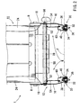
- an operation handle (an operation member) 56 is provided to one end (the right end in FIG. 2 ) of the operation shaft 50, so as to be positioned adjacent to the side frame element 16 (the side frame element 16 on the right side in FIG. 2 ), i.e., so as to be positioned on one of the side portions of the seat cushion 10.
- first or front ends 60a of the unlocking arms 60 are respectively linked to the link arms 52 via wires 54, so that the unlocking arms 60 can be rotated clockwise in FIG. 3 about the pivot pins 62 when the operation shaft 50 is rotated in the corresponding direction.
- second or rear ends 60b of the unlocking arms 60 may respectively contact the upper arm portions 42b of the lock members 42 so as to press the upper arm portions 42b downward when the unlocking arms 60 are rotated clockwise in FIG. 3 .
- the operation handle 56 of the operation mechanism M is first rotated clockwise in FIG. 3 , thereby rotating the operation shaft 50 in the same direction against a spring force of the second torsion spring.
- the wires 54 are pulled upwardly via the link arms 52, so that both of the unlocking arms 60 are synchronously rotated clockwise in FIGS 1 and 3 about the pivot pins 62.
- the upper arm portions 42b of the lock members 42 may preferably be pressed downward via the rear ends 60b of the unlocking arms 60, so that the lock members 42 is rotated counterclockwise in FIG. 4 about the hinge pins 44 against the spring force of the first torsion spring.
- the lower engagement portions 42a of the lock members 42 may preferably be disengaged from the engagement slots of the lower rails 34, so that the lock devices 40 can respectively be unlocked.
- the upper rails 32 can be freely slid back and forth along the lower rails 34, so as to be positioned at the desired position on the lower rails 34.
- the vehicle seat 1 connected to the upper rails 32 can be freely moved back and forth along the lower rails 34, so as to be positioned at the desired position on the lower rails 34.
- the vehicle seat 1 can be positioned at the desired position on the floor F.
- the operation handle 56 of the operation mechanism M is released.
- the operation shaft 50 is automatically rotated counterclockwise in FIG. 3 by the spring force of the second torsion spring, so that the unlocking arms 60 are rotated counterclockwise in FIGS 1 and 3 about the pivot pins 62.
- the lock members 42 are rotated clockwise in FIG. 4 about the hinge pins 44 by the spring force of the first torsion spring. Consequently, the lower engagement portions 42a of the lock members 42 may preferably be engaged with the engagement slots of the lower rails 34 again, so that the lock devices 40 are respectively locked again.
- the upper rail 32 may preferably be immobilized at the desired position on the lower rails 34.
- the vehicle seat 1 connected to the upper rail 32 may preferably be immobilized at the desired position on the lower rails 34, so as to be immobilized at the desired position on the floor F.
- the operation handle 56 can be disposed on one of the side portions of the seat cushion 10. That is, it is not necessary to dispose the operation handle 56 under the seat cushion 10. Therefore, as best shown in FIGS. 1 and 2 , it is possible to beneficially or effectively use a space under the seat cushion 10 (i.e., a space between the seat cushion 10 and the floor F).
- the operation shaft 50 of the operation mechanism M is linked to the lock devices 40 via a simplified linking mechanism (i.e., the link arms 52, the wires 54 and the unlocking arms 60). This may lead to a reduced manufacturing cost of the vehicle seat 1.
- the position of the operation shaft 50 can be changed longitudinally and vertically, if necessary.
- the linking mechanism can be modified, if necessary.
- the unlocking arms 60 can be directly linked to the link arms 52 without using the wires 54, if necessary.
Landscapes
- Engineering & Computer Science (AREA)
- Mechanical Engineering (AREA)
- Aviation & Aerospace Engineering (AREA)
- Transportation (AREA)
- Seats For Vehicles (AREA)
Description
- This application claims priority to Japanese patent application serial number
2007-131358 - The present invention relates to vehicle seats. More particularly, the present invention relates to vehicle seats that can be moved relative to a vehicle floor so that positions thereof can be adjusted.
- A mechanism for sliding a vehicle seat and adjusting positions thereof (i.e., a sliding and adjusting mechanism for a vehicle) is already known. The sliding and adjusting mechanism may include a pair of (right and left) slide rails that are disposed on a vehicle floor so as to extend in a longitudinal direction of the vehicle. The sliding and adjusting mechanism is arranged and constructed to move or slide the vehicle seat back and forth along the slide rails. Also, the sliding and adjusting mechanism may include a lock device that is constructed to lock or immobilize the vehicle seat at a desired position on the slide rails (i.e., the vehicle floor).
- The lock device may include a pair of lock members that are respectively attached to a seat cushion of the vehicle seat. The lock members are arranged and constructed to be engaged with and disengaged from the slide rails. The lock members are respectively linked to a U-shaped operation handle that is disposed under the seat cushion of the vehicle seat. Therefore, when the operation handle is operated, the lock members are simultaneously disengaged from the slide rails so that the lock device can be unlocked. Upon unlocking of the lock device, the vehicle seat can be released so as to be moved along the slide rails. Such a vehicle seat is taught, for example, by Japanese Laid-Open Patent Publication Number
2004-122825 - However, in the known vehicle seat, the U-shaped operation handle is disposed under the seat cushion of the vehicle seat. As a result, it is not possible to beneficially use a space between the seat cushion and the floor.
-
DE-A-19918600A discloses a seat release mechanism having the features of the pre-characterizing portion of Claim 1 appended hereto. - According to the invention there is provided a vehicle seat according to Claim 1 appended hereto.
- According to the vehicle seat thus constructed, it is possible to beneficially or effectively use a space under the seat cushion, i.e., a space between the seat cushion and the vehicle floor.
- Other objects, features and advantages of the present invention will be readily understood after reading the following detailed description together with the accompanying drawings and the claims.
-
FIG. 1 is a side view of a vehicle seat according to a representative embodiment of the present invention, which schematically illustrates a framework thereof; -
FIG. 2 is a rear view of the vehicle seat, which illustrates the framework thereof; -
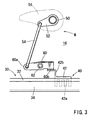
FIG. 3 is a partially enlarged view ofFIG. 1 ; and -
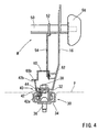
FIG. 4 is a partially enlarged view ofFIG. 2 . - A detailed representative embodiment of the present invention is shown in
FIG. 1 to FIG. 4 . - As shown in
FIGS. 1 and2 , a representative vehicle seat 1 may preferably include aseat cushion 10 and a seat back 20. Theseat cushion 10 may preferably be constituted of acushion frame 12 and apad 13 attached to thecushion frame 12. Thecushion frame 12 is composed of a tubularfront frame element 14 and a pair of plate-shapedside frame elements 16. Thecushion frame 12 further includes recliningplates 18 that are respectively attached to rear end portions of theside frame elements 16. Further, as best shown inFIG. 2 , theside frame elements 16 are connected to each other via a connectingrod 19. As a result, thecushion frame 12 can be reliably reinforced so as to have desired strength. - Similarly, the
seat back 20 may preferably be constituted of aback frame 22 and apad 23 attached to theback frame 22. Further, theback frame 22 includes a pair of plate-shapedside frame elements 24. Lower end portions of theside frame elements 24 are respectively rotatably connected to the recliningplates 18 of thecushion frame 12 via seat reclining devices R, so that a tilting angle of the back frame 22 (the seat back 20) relative to the cushion frame 12 (the seat cushion 10) can be adjusted by operating the seat reclining devices R (i.e., by switching the seat reclining devices R between a locked condition and an unlocked condition). As will be appreciated, the seat reclining devices R are arranged and constructed to be operated in synchronism with each other, so as to be simultaneously changed between the locked condition and the unlocked condition by simply operating an operation lever (not shown) that is generally attached to one of side portions of theseat cushion 10. - As shown in
FIGS. 1 and2 , the vehicle seat 1 may further include a pair of (right and left) slide rail assemblies (slide devices) 30 that are disposed on a floor F of a vehicle (not shown) so as to extend in a longitudinal direction of the vehicle. Theslide rail assemblies 30 are arranged and constructed such that the vehicle seat 1 can move or slide back and forth in the longitudinal direction of the vehicle. - In particular, each of the
slide rail assemblies 30 may preferably include an elongatedlower rail 34 and an elongatedupper rail 32. Thelower rail 34 is positioned on the floor F so as to extend in the longitudinal direction of the vehicle and is connected thereto via a plurality offixture pins 36. Conversely, theupper rail 32 slidably engages thelower rail 34 so as to slide or move therealong. Further, theupper rail 32 is connected to theside frame element 16 of thecushion frame 12 via a plurality offixture bolts 38. That is, theupper rail 32 is connected to the seat cushion 10 (the vehicle seat 1). - Each of the
slide rail assemblies 30 may further include alock device 40 that can releasably lock or immobilize theupper rail 32 on thelower rail 34, thereby immobilizing the vehicle seat 1 thereon. As best shown inFIGS. 3 and4 , thelock device 40 may preferably include alock member 42. As shown inFIG. 4 , thelock member 42 is pivotally connected to theupper rail 32 in the middle thereof via ahinge pin 44, so as to transversely rotate relative to the upper andlower rails lock member 42 may preferably include a bent fork-shapedlower engagement portion 42a and anupper arm portion 42b. Thelower engagement portion 42a is downwardly extended relative to thehinge pin 44. Also, thelower engagement portion 42a is shaped so as to be engaged with and disengaged from engagement apertures or slots (not shown) formed in thelower rail 34 via through holes (not shown) formed in theupper rail 32 upon rotation of thelock member 42. Conversely, theupper arm portion 42b is upwardly vertically extended relative to thehinge pin 44. - As will be recognized, when the
lower engagement portion 42a of thelock member 42 of thelock device 40 engages the engagement slots of thelower rails 34 via the through holes of theupper rail 32, thelock device 40 can be locked, so that theupper rail 32 can be locked or immobilized on thelower rail 34. As a result, the vehicle seat 1 connected to theupper rail 32 can be locked or immobilized on the floor F. - Further, the engagement slots of the
lower rail 34 may preferably be formed over the entire length of thelower rail 34 at desired intervals, so that theupper rail 32 can be positioned and immobilized at a desired position on thelower rail 34.
In addition, a first biasing member or torsion spring (not shown) is provided between thelock member 42 and thehinge pin 44. The torsion spring is arranged such that thelock member 42 is normally biased clockwise inFIG. 4 about thehinge pin 44. That is, the first torsion spring is arranged such that thelock member 42 is normally biased in such a direction in which thelower engagement portion 42a thereof can be engaged with the engagement slots of the lower rail 34 (i.e., in such a direction that thelock device 40 can be locked). Therefore, in order to disengage thelower engagement portion 42a from the engagement slots of the lower rail 34 (i.e., in order to unlock the lock device 40), thelock member 42 is rotated against a spring force of the first torsion spring. - Next, an operation mechanism M of the
lock devices 40 will be described.
As best shown inFIG. 2 , the operation mechanism M may preferably include a pair ofunlocking arms 60 that respectively correspond to thelock devices 40. The unlockingarms 60 are respectively disposed inside theside frame elements 16. As best shown inFIG. 3 , each of theunlocking arms 60 is rotatably attached to theside frame element 16 in the middle thereof via apivot pin 62. Further, as best shown inFIG. 2 , the operation mechanism M may further include a pair ofcantilever link arms 52 that are respectively disposed above the unlockingarms 60. Each of thelink arms 52 is fixedly connected to an operation shaft (a synchronization member) 50 that is transversely disposed between theside frame elements 16. Theoperation shaft 50 are rotatably attached to theside frame elements 16 at both ends thereof. Further, a second biasing member or torsion spring (not shown) may preferably be provided between theoperation shaft 50 and theside frame elements 16. The second torsion spring is arranged such that theoperation shaft 50 is normally biased counterclockwise inFIG. 3 . In addition, an operation handle (an operation member) 56 is provided to one end (the right end inFIG. 2 ) of theoperation shaft 50, so as to be positioned adjacent to the side frame element 16 (theside frame element 16 on the right side inFIG. 2 ), i.e., so as to be positioned on one of the side portions of theseat cushion 10. - As shown in
FIGS. 2 and3 , first orfront ends 60a of the unlockingarms 60 are respectively linked to thelink arms 52 viawires 54, so that the unlockingarms 60 can be rotated clockwise inFIG. 3 about the pivot pins 62 when theoperation shaft 50 is rotated in the corresponding direction. Conversely, second orrear ends 60b of the unlockingarms 60 may respectively contact theupper arm portions 42b of thelock members 42 so as to press theupper arm portions 42b downward when the unlockingarms 60 are rotated clockwise inFIG. 3 . - Next, an operation of the vehicle seat 1 thus constructed will be described.
In order to slide or move the vehicle seat 1 back and forth on the floor F and to position and immobilize the vehicle seat 1 at a desired position on the floor F, the operation handle 56 of the operation mechanism M is first rotated clockwise inFIG. 3 , thereby rotating theoperation shaft 50 in the same direction against a spring force of the second torsion spring. Upon rotation of theoperation shaft 50, thewires 54 are pulled upwardly via thelink arms 52, so that both of the unlockingarms 60 are synchronously rotated clockwise inFIGS 1 and3 about the pivot pins 62. As a result, theupper arm portions 42b of thelock members 42 may preferably be pressed downward via the rear ends 60b of the unlockingarms 60, so that thelock members 42 is rotated counterclockwise inFIG. 4 about the hinge pins 44 against the spring force of the first torsion spring. Upon rotation of thelock member 42, thelower engagement portions 42a of thelock members 42 may preferably be disengaged from the engagement slots of thelower rails 34, so that thelock devices 40 can respectively be unlocked. As a result, theupper rails 32 can be freely slid back and forth along thelower rails 34, so as to be positioned at the desired position on the lower rails 34. Consequently, the vehicle seat 1 connected to theupper rails 32 can be freely moved back and forth along thelower rails 34, so as to be positioned at the desired position on the lower rails 34. Thus, the vehicle seat 1 can be positioned at the desired position on the floor F. - After the
upper rails 32 are positioned at the desired position on thelower rails 34, the operation handle 56 of the operation mechanism M is released. As a result, theoperation shaft 50 is automatically rotated counterclockwise inFIG. 3 by the spring force of the second torsion spring, so that the unlockingarms 60 are rotated counterclockwise inFIGS 1 and3 about the pivot pins 62. Upon rotation of the unlockingarms 60, thelock members 42 are rotated clockwise inFIG. 4 about the hinge pins 44 by the spring force of the first torsion spring. Consequently, thelower engagement portions 42a of thelock members 42 may preferably be engaged with the engagement slots of thelower rails 34 again, so that thelock devices 40 are respectively locked again. As a result, theupper rail 32 may preferably be immobilized at the desired position on the lower rails 34. Thus, the vehicle seat 1 connected to theupper rail 32 may preferably be immobilized at the desired position on thelower rails 34, so as to be immobilized at the desired position on the floor F. - According to the vehicle seat 1 of the present embodiment, the operation handle 56 can be disposed on one of the side portions of the
seat cushion 10. That is, it is not necessary to dispose the operation handle 56 under theseat cushion 10. Therefore, as best shown inFIGS. 1 and2 , it is possible to beneficially or effectively use a space under the seat cushion 10 (i.e., a space between theseat cushion 10 and the floor F). - Further, the
operation shaft 50 of the operation mechanism M is linked to thelock devices 40 via a simplified linking mechanism (i.e., thelink arms 52, thewires 54 and the unlocking arms 60). This may lead to a reduced manufacturing cost of the vehicle seat 1. - Naturally, various changes and modifications may be made to the present invention without departing from the scope of the invention. For example, the position of the
operation shaft 50 can be changed longitudinally and vertically, if necessary.
Further, the linking mechanism can be modified, if necessary. For example, the unlockingarms 60 can be directly linked to thelink arms 52 without using thewires 54, if necessary. - A representative example of the present invention has been described in detail with reference to the attached drawings. This detailed description is merely intended to teach a person of skill in the art further details for practicing preferred aspects of the present invention and is not intended to limit the scope of the invention. Only the claims define the scope of the claimed invention. Therefore, combinations of features and steps disclosed in the foregoing detail description may not be necessary to practice the invention in the broadest sense, and are instead taught merely to particularly describe detailed representative examples of the invention.
Claims (1)
- A vehicle seat (1) comprising a seat cushion (10) having side portions in a vehicle width direction, and
a pair of slide devices (30) adapted to be disposed on a vehicle floor (F) in a vehicle length direction, the slide devices (30) being arranged and constructed to slide the vehicle seat (1) on the vehicle floor (F);
a pair of lock devices (40) respectively provided to the slide devices (30), the lock devices (40) being capable of releasably locking the vehicle seat (1) at a desired position on the vehicle floor (F) by releasable engagement with said slide devices (30),
an operation mechanism (M) of the lock devices (40),
wherein the operation mechanism (M) includes a synchronization member (50) having an operating handle (56), and wherein the synchronization member (50) is disposed above the slide devices (30) and is linked to the lock devices (40) via a linking mechanism (52, 54, 60), said synchronization member (50) being disposed between said side portions of the seat cushion (10), wherein the operating handle (56) is connected to the synchronization member (50) so as to be positioned on one of the side portions of the seat cushion (10), and wherein the linking mechanism (52, 54, 60) is arranged and constructed such that said lock devices (40) can be released when the synchronization member (50) is operated via the operating handle (56),
characterized in that
said synchronization member comprises a shaft (50) rotatable in side frame elements (16) of said seat, said operating handle (56) being provided at one end of said shaft (50) adjacent one of said side frame elements (16),
said lock devices (40) having respective unlocking arms (60) rotatably attached to respective side frame elements (16)
said shaft (50) having a pair of cantilever link arms (52) disposed above respective unlocking arms (60), and
wires (54) linking respective unlocking arms (60) and cantilever link arms (52) so as to operate said lock devices upon pivoting of the shaft (50) by the operating handle (56).
Applications Claiming Priority (1)
| Application Number | Priority Date | Filing Date | Title |
|---|---|---|---|
| JP2007131358A JP5225610B2 (en) | 2007-05-17 | 2007-05-17 | Vehicle seat |
Publications (3)
| Publication Number | Publication Date |
|---|---|
| EP2003012A2 EP2003012A2 (en) | 2008-12-17 |
| EP2003012A3 EP2003012A3 (en) | 2009-10-28 |
| EP2003012B1 true EP2003012B1 (en) | 2011-04-06 |
Family
ID=39887440
Family Applications (1)
| Application Number | Title | Priority Date | Filing Date |
|---|---|---|---|
| EP08156404A Active EP2003012B1 (en) | 2007-05-17 | 2008-05-16 | Vehicle seats |
Country Status (4)
| Country | Link |
|---|---|
| US (1) | US7794018B2 (en) |
| EP (1) | EP2003012B1 (en) |
| JP (1) | JP5225610B2 (en) |
| DE (1) | DE602008005954D1 (en) |
Families Citing this family (6)
| Publication number | Priority date | Publication date | Assignee | Title |
|---|---|---|---|---|
| JP5275622B2 (en) * | 2007-12-26 | 2013-08-28 | トヨタ紡織株式会社 | Vehicle seat |
| JP5119911B2 (en) * | 2007-12-26 | 2013-01-16 | トヨタ紡織株式会社 | Vehicle seat |
| JP5119910B2 (en) * | 2007-12-26 | 2013-01-16 | トヨタ紡織株式会社 | Vehicle seat |
| JP5181866B2 (en) * | 2008-06-24 | 2013-04-10 | トヨタ紡織株式会社 | Vehicle seat switching mechanism |
| KR101553526B1 (en) | 2013-12-29 | 2015-09-17 | 현대다이모스(주) | Slide lever apparatus for seat of vehicle |
| FR3024079B1 (en) * | 2014-07-25 | 2018-03-09 | Faurecia Sieges D'automobile | VEHICLE SEAT AND METHOD OF ADJUSTING A VEHICLE SEAT |
Family Cites Families (29)
| Publication number | Priority date | Publication date | Assignee | Title |
|---|---|---|---|---|
| US2667912A (en) * | 1951-09-11 | 1954-02-02 | Charles E Mccormick | Adjustable seat supporting means |
| DE1505747C3 (en) * | 1966-05-20 | 1982-08-12 | Daimler-Benz Ag, 7000 Stuttgart | Motor vehicle seat mounted so as to be longitudinally displaceable |
| US3582033A (en) * | 1969-06-05 | 1971-06-01 | Howell Ind Inc | Adjustable vehicle seat mounting |
| FR2060183A1 (en) * | 1969-09-10 | 1971-06-18 | Peugeot & Renault | |
| FR2288645A1 (en) * | 1974-02-20 | 1976-05-21 | Peugeot & Renault | FOLDING BACK SEAT FOR VEHICLE |
| JPS58199233A (en) | 1982-05-12 | 1983-11-19 | Mitsubishi Motors Corp | Bench seat for car |
| JPS607234U (en) * | 1983-06-28 | 1985-01-18 | トヨタ自動車株式会社 | Seat walk-in device |
| JPS60179534U (en) * | 1984-05-11 | 1985-11-28 | 本田技研工業株式会社 | Seat slide lock device |
| JPH0511068Y2 (en) * | 1987-11-17 | 1993-03-18 | ||
| JPH0483832U (en) * | 1990-11-29 | 1992-07-21 | ||
| EP0606547B1 (en) * | 1992-11-14 | 1996-12-27 | C. Rob. Hammerstein GmbH | Locking arrangement for a longitudinal adjustment device of a vehicle seat |
| DE19510618A1 (en) * | 1994-05-19 | 1995-11-23 | Hammerstein Gmbh C Rob | Vehicle seat, which can be moved longitudinally if backrest is folded |
| JPH08324313A (en) * | 1995-05-31 | 1996-12-10 | Tachi S Co Ltd | Lock device for slide rail |
| FR2736311B1 (en) * | 1995-07-04 | 1997-09-05 | Faure Bertrand Equipements Sa | LOCKABLE SLIDE IN POSITION FOR MOTOR VEHICLE SEATS |
| US5570931A (en) * | 1995-09-29 | 1996-11-05 | Chrysler Corporation | Vehicle adjustable and stowable rear seat |
| US5597206A (en) * | 1995-10-31 | 1997-01-28 | Douglas & Lomason Company | Easy entry seat adjuster |
| WO1998054024A1 (en) * | 1997-05-27 | 1998-12-03 | Bertrand Faure Components Ltd. | Slide/fold/ez entry seat mechanism |
| SE511350C2 (en) * | 1997-11-11 | 1999-09-13 | Scania Cv Ab | Arrangements for the regulation of a vehicle seat |
| FR2772686B3 (en) * | 1997-12-22 | 2000-02-18 | Faure Bertrand Equipements Sa | SEAT KIT FOR VEHICLE INCLUDING A REMOVABLE SEAT MOUNTED ON SLIDES |
| FR2777836B1 (en) | 1998-04-23 | 2000-07-21 | Faure Bertrand Equipements Sa | SLIDE FOR VEHICLE SEAT, AND SEAT COMPRISING SUCH A SLIDE |
| JP3581574B2 (en) | 1998-07-30 | 2004-10-27 | 富士機工株式会社 | Seat reclining device |
| FR2781732B1 (en) * | 1998-07-31 | 2000-10-06 | Irausa Ingeniera Sa | VEHICLE SEAT, REMOVABLE, TURNABLE AND LONGITUDINALLY ADJUSTABLE BY CONTROLS ON ITS SLIDES |
| DE10048228A1 (en) * | 2000-09-21 | 2002-04-25 | Brose Fahrzeugteile | Device for adjusting the backrest angle |
| FR2830804B1 (en) * | 2001-10-15 | 2004-01-16 | Faurecia Sieges Automobile | VEHICLE SEAT HAVING A FOLDING BACK FORWARD |
| JP2004122825A (en) | 2002-09-30 | 2004-04-22 | Delta Kogyo Co Ltd | Lock mechanism for slide adjuster for vehicles |
| DE102005039903B3 (en) * | 2005-08-24 | 2006-12-07 | Faurecia Autositze Gmbh & Co. Kg | Seat for motor vehicle has connecting element with inner shaft fixed to left and right end regions of unlocking devices |
| JP2007131358A (en) | 2005-11-08 | 2007-05-31 | Fuji Iron Works Co Ltd | Web cutting and winding device with ironing bar, and its method |
| JP5103028B2 (en) * | 2007-01-29 | 2012-12-19 | トヨタ紡織株式会社 | Vehicle seat |
| JP5103027B2 (en) * | 2007-01-29 | 2012-12-19 | トヨタ紡織株式会社 | Vehicle seat |
-
2007
- 2007-05-17 JP JP2007131358A patent/JP5225610B2/en active Active
-
2008
- 2008-05-16 US US12/121,890 patent/US7794018B2/en active Active
- 2008-05-16 DE DE602008005954T patent/DE602008005954D1/en active Active
- 2008-05-16 EP EP08156404A patent/EP2003012B1/en active Active
Also Published As
| Publication number | Publication date |
|---|---|
| JP2008284985A (en) | 2008-11-27 |
| DE602008005954D1 (en) | 2011-05-19 |
| US7794018B2 (en) | 2010-09-14 |
| EP2003012A2 (en) | 2008-12-17 |
| US20080284197A1 (en) | 2008-11-20 |
| EP2003012A3 (en) | 2009-10-28 |
| JP5225610B2 (en) | 2013-07-03 |
Similar Documents
| Publication | Publication Date | Title |
|---|---|---|
| EP2003012B1 (en) | Vehicle seats | |
| EP1790522B1 (en) | Walk-in device | |
| EP1839938B1 (en) | Seat structure for vehicle | |
| US8038217B2 (en) | Vehicle seat | |
| CN111601732B (en) | Vehicle seat convenient to enter | |
| CN100567044C (en) | Seats retractable into the floor and vehicles incorporating such seats | |
| US8439443B2 (en) | Vehicle seat | |
| US9296318B2 (en) | Vehicle seat | |
| KR20010006144A (en) | Single control handle release mechanism for use with a vehicle seat | |
| JPH0281738A (en) | Seat device for vehicle | |
| CN101821127A (en) | Vehicle seat | |
| CN105346412A (en) | Device of folding seat for vehicle | |
| CN112092688A (en) | Seat assembly | |
| EP1452387A2 (en) | Retractable seats | |
| EP3853062B1 (en) | A seat assembly for use in an automotive vehicle for movement between a plurality of positions | |
| CN115515820A (en) | Vehicle seat with motion bar | |
| US6974184B1 (en) | Locking mechanism assembly for a cantilevered stowable seat | |
| JP5007605B2 (en) | Unlocking mechanism for vehicle seat | |
| JP2009262803A (en) | Vehicular seat | |
| WO2010151259A1 (en) | Vehicle seat assembly | |
| JPH07304359A (en) | Vehicle seat | |
| JP2009023384A (en) | Seat for vehicle | |
| JP2001270351A (en) | Seat device | |
| JP3489671B2 (en) | Lock mechanism for seat slide device | |
| JPH11113669A (en) | Car seat |
Legal Events
| Date | Code | Title | Description |
|---|---|---|---|
| PUAI | Public reference made under article 153(3) epc to a published international application that has entered the european phase |
Free format text: ORIGINAL CODE: 0009012 |
|
| 17P | Request for examination filed |
Effective date: 20080516 |
|
| AK | Designated contracting states |
Kind code of ref document: A2 Designated state(s): AT BE BG CH CY CZ DE DK EE ES FI FR GB GR HR HU IE IS IT LI LT LU LV MC MT NL NO PL PT RO SE SI SK TR |
|
| AX | Request for extension of the european patent |
Extension state: AL BA MK RS |
|
| PUAL | Search report despatched |
Free format text: ORIGINAL CODE: 0009013 |
|
| AK | Designated contracting states |
Kind code of ref document: A3 Designated state(s): AT BE BG CH CY CZ DE DK EE ES FI FR GB GR HR HU IE IS IT LI LT LU LV MC MT NL NO PL PT RO SE SI SK TR |
|
| AX | Request for extension of the european patent |
Extension state: AL BA MK RS |
|
| 17Q | First examination report despatched |
Effective date: 20100120 |
|
| AKX | Designation fees paid |
Designated state(s): DE FR TR |
|
| GRAP | Despatch of communication of intention to grant a patent |
Free format text: ORIGINAL CODE: EPIDOSNIGR1 |
|
| GRAS | Grant fee paid |
Free format text: ORIGINAL CODE: EPIDOSNIGR3 |
|
| GRAA | (expected) grant |
Free format text: ORIGINAL CODE: 0009210 |
|
| AK | Designated contracting states |
Kind code of ref document: B1 Designated state(s): DE FR TR |
|
| REF | Corresponds to: |
Ref document number: 602008005954 Country of ref document: DE Date of ref document: 20110519 Kind code of ref document: P |
|
| REG | Reference to a national code |
Ref country code: DE Ref legal event code: R096 Ref document number: 602008005954 Country of ref document: DE Effective date: 20110519 |
|
| PLBE | No opposition filed within time limit |
Free format text: ORIGINAL CODE: 0009261 |
|
| STAA | Information on the status of an ep patent application or granted ep patent |
Free format text: STATUS: NO OPPOSITION FILED WITHIN TIME LIMIT |
|
| 26N | No opposition filed |
Effective date: 20120110 |
|
| REG | Reference to a national code |
Ref country code: DE Ref legal event code: R097 Ref document number: 602008005954 Country of ref document: DE Effective date: 20120110 |
|
| REG | Reference to a national code |
Ref country code: FR Ref legal event code: PLFP Year of fee payment: 9 |
|
| REG | Reference to a national code |
Ref country code: FR Ref legal event code: PLFP Year of fee payment: 10 |
|
| REG | Reference to a national code |
Ref country code: FR Ref legal event code: PLFP Year of fee payment: 11 |
|
| REG | Reference to a national code |
Ref country code: FR Ref legal event code: PLFP Year of fee payment: 16 |
|
| PGFP | Annual fee paid to national office [announced via postgrant information from national office to epo] |
Ref country code: DE Payment date: 20250402 Year of fee payment: 18 |
|
| PGFP | Annual fee paid to national office [announced via postgrant information from national office to epo] |
Ref country code: FR Payment date: 20250401 Year of fee payment: 18 |
|
| PGFP | Annual fee paid to national office [announced via postgrant information from national office to epo] |
Ref country code: TR Payment date: 20250507 Year of fee payment: 18 |