EP2002945A1 - Fitting apparatus for fitting two workpieces to each other - Google Patents
Fitting apparatus for fitting two workpieces to each other Download PDFInfo
- Publication number
- EP2002945A1 EP2002945A1 EP08010707A EP08010707A EP2002945A1 EP 2002945 A1 EP2002945 A1 EP 2002945A1 EP 08010707 A EP08010707 A EP 08010707A EP 08010707 A EP08010707 A EP 08010707A EP 2002945 A1 EP2002945 A1 EP 2002945A1
- Authority
- EP
- European Patent Office
- Prior art keywords
- force
- workpiece
- moment
- gripper
- axis
- Prior art date
- Legal status (The legal status is an assumption and is not a legal conclusion. Google has not performed a legal analysis and makes no representation as to the accuracy of the status listed.)
- Granted
Links
Images


Classifications
-
- B—PERFORMING OPERATIONS; TRANSPORTING
- B25—HAND TOOLS; PORTABLE POWER-DRIVEN TOOLS; MANIPULATORS
- B25J—MANIPULATORS; CHAMBERS PROVIDED WITH MANIPULATION DEVICES
- B25J9/00—Programme-controlled manipulators
- B25J9/16—Programme controls
- B25J9/1628—Programme controls characterised by the control loop
- B25J9/1633—Programme controls characterised by the control loop compliant, force, torque control, e.g. combined with position control
-
- B—PERFORMING OPERATIONS; TRANSPORTING
- B25—HAND TOOLS; PORTABLE POWER-DRIVEN TOOLS; MANIPULATORS
- B25J—MANIPULATORS; CHAMBERS PROVIDED WITH MANIPULATION DEVICES
- B25J9/00—Programme-controlled manipulators
- B25J9/16—Programme controls
- B25J9/1679—Programme controls characterised by the tasks executed
- B25J9/1687—Assembly, peg and hole, palletising, straight line, weaving pattern movement
-
- G—PHYSICS
- G05—CONTROLLING; REGULATING
- G05B—CONTROL OR REGULATING SYSTEMS IN GENERAL; FUNCTIONAL ELEMENTS OF SUCH SYSTEMS; MONITORING OR TESTING ARRANGEMENTS FOR SUCH SYSTEMS OR ELEMENTS
- G05B2219/00—Program-control systems
- G05B2219/30—Nc systems
- G05B2219/39—Robotics, robotics to robotics hand
- G05B2219/39529—Force, torque sensor in wrist, end effector
-
- G—PHYSICS
- G05—CONTROLLING; REGULATING
- G05B—CONTROL OR REGULATING SYSTEMS IN GENERAL; FUNCTIONAL ELEMENTS OF SUCH SYSTEMS; MONITORING OR TESTING ARRANGEMENTS FOR SUCH SYSTEMS OR ELEMENTS
- G05B2219/00—Program-control systems
- G05B2219/30—Nc systems
- G05B2219/40—Robotics, robotics mapping to robotics vision
- G05B2219/40032—Peg and hole insertion, mating and joining, remote center compliance
Definitions
- the present invention relates to a fitting apparatus for fitting two workpieces to each other using a robot while performing compliance control or force control.
- a fitting apparatus for fitting two workpieces to each other generally uses a RCC (remote center compliance) mechanism in which a spring or a damper is interposed between the robot arm and the robot gripper to thereby provide a mechanically elastic motion of the gripper mounted at the forward end of the robot arm, so that one workpiece held in the gripper can be fitted smoothly with the other workpiece by automatically changing the position and the orientation of the one workpiece held in the gripper even in the presence of some position error or orientation error.
- RCC remote center compliance
- a compliance control method or force control method can be used in which the robot is operated as if there exists a spring or a damper between the robot arm and the robot gripper by controlling the operation of the robot arm to thereby obtain the same effect as the RCC mechanism.
- one of the two workpieces to be fitted to each other is held by the gripper of the robot arm and pressed against the other workpiece to thereby carry out the fitting operation, while the force and moment exerting on the workpiece held by the gripper are detected and the operation of the robot arm is controlled and corrected so as to bring the detected force and moment to a target value.
- the difference between the detected force and the target force and the difference between the detected moment and the target moment are multiplied by a parameter called a force control gain to thereby calculate a command velocity and a command angular velocity for the robot arm. Based on the command velocity and the command angular velocity thus calculated, the workpiece held by the gripper is translated and rotated. Therefore, the force control gain exhibits the force control performance and a larger value of the force control gain can achieve a quicker correction of the position and orientation of the workpiece held by the gripper.
- the force control gain can be increased only to a value determined by the oscillation limit, and in the system having an initial error in the position and orientation of the workpieces and the robot arm, the error correction requires a vast amount of time.
- the operation command for the robot arm is corrected, in every control cycle of the controller, based on either maximum value of the force and moment detected by the force detector while the two workpieces are in contact with each other or the force and moment detected by the force detector when the two workpieces first come into contact with each other, and the position of the gripper and workpiece in the direction perpendicular to the fitting direction and the orientation of the gripper and workpiece around the axis perpendicular to the fitting direction are corrected until the force and moment detected by the force detector are reduced to or less than the predetermined threshold value.
- the force and moment of the workpiece held by the gripper are detected in every control cycle, and the force and moment thus detected are used only for monitoring whether or not they are reduced to or less than the predetermined threshold value. Therefore, even if the force detection means is accompanied by noises due to the vibration of the robot arm or workpiece, the correcting operation is not substantially affected, and the force control gain can be set to a larger value than that in the prior art.
- the operation command correcting unit preferably corrects the operation command so as to reduce the force and moment detected by the force detector.
- the force detector detects the forces exerting in the directions along two axes perpendicular to the fitting direction and perpendicular to each other, and the operation command correcting unit corrects the operation command based on the forces in the directions along the two axes detected by the force detector to thereby correct the position of the gripper in the directions perpendicular to the fitting direction.
- the force detector detects the moments around the two axes perpendicular to the fitting direction and perpendicular to each other, and the operation command correcting unit corrects the operation command based on the moments around the two axes detected by the force detector to thereby correct the orientation of the gripper around the axes perpendicular to the fitting direction.
- the operation command correcting unit preferably corrects the operation command until the force and moment detected by the force detector are reduced to zero.
- the force detector can be a force sensor.
- the force detector may determine the force and moment received by the workpiece, based on a current value of an actuator for driving the robot arm.
- the correcting operation is not affected, and a force control gain can be set to a larger value than that in the prior art, thereby making it possible to correct an initial error, if any in the workpieces or the robot arm, quicker than in the prior art.
- a force control gain can be set to a larger value than that in the prior art, thereby making it possible to correct an initial error, if any in the workpieces or the robot arm, quicker than in the prior art.
- the fitting apparatus 10 includes a robot arm 12 adapted to be able to move around a plurality of axes, a force detector 14 for detecting a force and a moment, a controller 16 for controlling an operation of robot arm 12, and a table 18 for mounting a workpiece W1 thereon.
- a gripper 20 adapted to be able to hold and release a workpiece W2 is provided at the forward end of robot arm 12.
- a clamp unit 22 for fixing workpiece W1 is provided on table 18, so that workpiece W1 to be fitted to workpiece W2 held by gripper 20 can be fixed removably to table 18.
- Force detector 14 is mounted on the wrist of robot arm 12 so that force F and moment M received by workpiece W2 held by gripper 20 can be detected.
- force detector 14 can be a 6-axis force sensor, which is mounted between the forward end of robot arm 12 and gripper 20 and adapted to be able to detect forces in directions along three orthogonal axes and moments around three orthogonal axes.
- force detector 14 is not limited to the 6-axis force sensor, but may be any device for estimating the force and the moment received by workpiece W2 held by gripper 20, based on a current value of an actuator (not shown) such as a motor for driving robot arm 12.
- Workpieces W1, W2 to be fitted to each other may be constituted, for example, by a workpiece W2 having a cylindrical protrusion 24 and a workpiece W1 formed with a cylindrical fitting hole 26 mating with cylindrical protrusion 24.
- fitting apparatus 10 shown in Fig. 1 workpiece W2 having protrusion 24 is held by gripper 20 and moved in the fitting direction parallel to a center axis 28 of fitting hole 26 with protrusion 24 aligned with center axis 28 of fitting hole 26 of workpiece W1 fixed to table 18, so that protrusion 24 of workpiece 2 is inserted into fitting hole 26 of workpiece W1 to thereby fit two workpieces W1, W2 to each other.
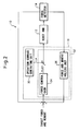
- Fig. 2 is a function block diagram of fitting apparatus 10 according to the present invention, showing the detail of control unit 16 used in fitting apparatus 10.
- Controller 16 includes an operation command generating unit 30 for generating an operation command for robot arm 12 and gripper 20, and an operation command correcting unit 32 for correcting, under predetermined conditions, the operation command generated by operation command generating unit 30.
- Operation command generating unit 30 in accordance with a program input in advance or the like, generates operation commands, specifically a velocity command and an angular velocity command, for robot arm 12 and gripper 20 thereof so as to make gripper 20 hold one workpiece W2 included in two workpieces W1, W2 to be fitted to each other at a predetermined place and fit it to the other workpiece W1 fixed at a predetermined place on table 18.
- Operation command correcting unit 32 is configured of a force control gain unit 34 and a force and moment holding unit 36;
- Force and moment holding unit 36 is implemented by a storage unit such as a RAM and adapted to store or hold maximum values F', M' of force F and moment M detected by force detector 14 while workpiece W2 held by gripper 20 and workpiece W1 fixed to table 18 are in contact with each other, and values F0, M0 of force F and moment M detected by force detector 14 when workpiece W2 held by gripper 20 and workpiece W1 fixed to table 18 first come into contact with each other.
- a storage unit such as a RAM and adapted to store or hold maximum values F', M' of force F and moment M detected by force detector 14 while workpiece W2 held by gripper 20 and workpiece W1 fixed to table 18 are in contact with each other, and values F0, M0 of force F and moment M detected by force detector 14 when workpiece W2 held by gripper 20 and workpiece W1 fixed to table 18 first come into contact with each other.
- Force control gain unit 34 upon input of the difference between forces F', F0 and moments M', M0 held in force and moment holding unit 36 and a target force Fd and a target moment Md to be detected by force detector 14 when workpieces W1, W2 are fitted to each other, multiplies the input by a force control gain G to thereby output a velocity command correction amount ⁇ c and an angular velocity command correction amount ⁇ c for causing robot arm 12 and gripper 20 to perform the motion required to make force F and moment M detected by force detector 14 approach target force Fd and target moment Md, respectively.
- Operation command correcting unit 32 corrects velocity command u and angular velocity command ⁇ by adding velocity command correction amount ⁇ c and angular velocity command correction amount ⁇ c output from force control gain unit 34 to velocity command u and angular velocity command ⁇ generated by operation command generating unit 30, respectively, and causes robot arm 12 and gripper 20 thereof to move based on corrected velocity command ⁇ ' and corrected angular velocity command ⁇ '.
- the correction of the operation commands by operation command correcting unit 32 is continued until force F and moment M detected by force detector 14 are reduced to less than or equal to predetermined threshold values TF, TM, respectively.
- a Z-axis represents a direction of center axis 28 of fitting hole 26 of workpiece W1 fixed to table 18, and X- and Y-axes represent directions perpendicular to each other in a plane perpendicular to the Z-axis.
- one workpiece w1 included in workpiece pair W1, W2 to be fitted to each other is fixed at a predetermined place on table 18 by the operator or another robot.
- robot arm 12 holds, by gripper 20 thereof, mating workpiece W2 arranged at a predetermined place, and moves workpiece W2 to a place in opposed relation to workpiece W1 fixed to table 18 so as to align the axis of protrusion 24 of workpiece w2 held by gripper 20 with center axis 28 of fitting hole 26 of workpiece W1 fixed to table 18.
- Robot arm 12 further moves workpiece W2 in the fitting direction (i.e.
- step S102 For example, in the case where, as shown in Fig.
- axis 38 of protrusion 24 of workpiece W2 held by gripper 20 is inclined with respect to center axis 28 of fitting hole 26 of workpiece W1 fixed to table 18, when two workpieces W1, W2 come into contact with each other, forces F X and F Y in the directions perpendicular to the fitting direction and moments M X , M Y around the axes perpendicular to the fitting direction exert on workpiece W2 held by gripper 20, as shown in Fig. 4B .
- controller 16 controls the operation of robot arm 12 and gripper 20 such that force F and moment M detected by force detector 14 approach target force Fd and target moment Md, respectively.
- the maximum values of force F(F X , F Y , F Z ) and moment M(M X , M Y , M Z ) detected by force detector 14 while workpiece W1 fixed to table 18 and workpiece W2 held by gripper 20 are in contact with each other are stored or held in force and moment holding unit 36.
- force and moment holding unit 36 compares the components of force F(F x , Fy, F z ) and moment M (M X , M Y , M z ) detected by force detector 14 with the corresponding components of force F' (F' x , F' Y , F' z ) and moment M' (M' x , M' Y , M' z ) stored or held in force and moment holding unit 36.
- operation command correcting unit 32 multiplies the difference between Z-axis force F Z detected by force detector 14 and Z-axis target force Fd Z by force control gain Gz to thereby calculate a velocity command correction value ⁇ c Z , and adds calculated velocity command correction value ⁇ c Z to Z-axis velocity command ⁇ Z generated by operation command generating unit 30 to thereby correct Z-axis velocity command ⁇ Z .
- a corrected Z-axis velocity command ⁇ ' Z is determined.
- ⁇ Z F Z - Fd Z x G Z + ⁇ Z
- protrusion 24 of workpiece W2 and fitting hole 26 of workpiece W1 are cylindrical and the rotation around Z-axis is meaningless. Therefore, angular velocity command ⁇ R around Z-axis and corrected angular velocity ⁇ ' R around Z-axis are not required to be determined.
- operation command correcting unit 32 multiplies the difference between maximum values F', M' of the force and moment stored or held in force and moment holding unit 36 and target force Fd and target moment Md by force control gain G to thereby calculate velocity command correction amounts ⁇ c X , ⁇ c Y and angular velocity command correction amounts ⁇ CW ⁇ c P , and adds calculated velocity command correction amounts ⁇ c X , ⁇ c Y and angular velocity command correction amounts ⁇ CW , ⁇ c P to X-axis velocity command ⁇ X , Y-axis velocity command ⁇ Y , angular velocity command around X-axis ⁇ W and angular velocity command around Y-axis ⁇ P generated by operation command generating unit 30, respectively, to thereby correct X-axis velocity command ⁇ X , Y-axis velocity command ⁇ Y , angular velocity command around X-axis ⁇ W and angular velocity command around Y-axis ⁇ P generated by operation command generating
- corrected X-axis velocity command ⁇ ' x , corrected Y-axis velocity command ⁇ ' Y , corrected angular velocity command around X-axis ⁇ ' w and corrected angular velocity command around Y-axis ⁇ ' P can be determined from following Equations (2) to (5).
- G X , G Y represent the force control gain of the X-axis force and the force control gain of the Y-axis force, respectively
- G w , G p represent the force control gain of the moment around X-axis and the force control gain of the moment around Y-axis, respectively.
- the fitting operation is an operation of moving gripper 20 and workpiece W2 only in the fitting direction, i.e. along Z-axis, and in the fitting operation, X-axis velocity command ⁇ X , Y-axis velocity command ⁇ Y , angular velocity command around X-axis ⁇ W and angular velocity command around Y-axis ⁇ P are all zero.
- operation command correction amounts ⁇ c X , ⁇ c Y , ⁇ c W , ⁇ c p determined by operation command correcting unit 32 become corrected X-axis velocity command ⁇ ' X , corrected Y-axis velocity command ⁇ ' Y , corrected angular velocity command around X-axis ⁇ ' W and corrected angular velocity command around Y-axis ⁇ ' P , respectively.
- operation command correcting unit 32 determines ⁇ ' X , ⁇ ' Y , ⁇ ' W , ⁇ ' P as the X-axis velocity command, the Y-axis velocity command, the angular velocity commands around X-axis and the angular velocity command around Y-axis, respectively, by multiplying maximum values F', M' of the force and the moment stored or held in force and moment holding unit 36 by force control gain G.
- Controller 16 operates robot arm 12 and gripper 20, based on corrected X-axis velocity command ⁇ ' X , corrected Y-axis velocity command ⁇ ' Y , corrected Z-axis velocity command ⁇ ' Z , corrected angular velocity command around X-axis ⁇ ' W and corrected angular velocity command around Y-axis ⁇ ' P thus determined, and corrects the position and orientation of gripper 20 and workpiece W2 (step S104).
- step S104 X- and Y-axis forces F X , F Y and moments M X , M Y around X- and Y-axes detected by force detector 14 are compared with predetermined threshold values TF X , TF Y , TM X , TM Y , respectively, in every control cycle, and if any of the former values is larger than a predetermined corresponding threshold value, the process of step S104 is repeated in every control cycle and the correction of the position and orientation of gripper 20 and workpiece W2 is continued until all of F X , F Y , M X , M Y satisfy following Equation (6) (step S106).
- threshold values TF X , TF Y are ones associated with X-axis force F X and Y-axis force F Y detected, respectively
- threshold values TM X , TM Y are ones associated with moment M x around X-axis and moment M Y around Y-axis, respectively.
- step S108 it is judged that the error correction of the position and orientation of gripper 20 and workpiece W2 has been completed.
- axis 38 of protrusion 24 of workpiece W2 held by gripper 20 is aligned with center axis 28 of fitting hole 26 of workpiece W1 fixed to table 18.
- step S110 by moving gripper 20 and workpiece W2 in the fitting direction while keeping this position and orientation, protrusion 24 of workpiece W2 held by gripper 20 can be smoothly inserted into fitting hole 26 of workpiece W1 fixed to table 18, as shown in Fig. 4D , thereby completing the fitting operation (step S110).
- maximum values F' (F' x , F' Y , F' z ) and M'(M' X , M' Y , M' z ') of force F and moment M detected by force detector 14 while workpiece W1 and workpiece W2 are in contact with each other are stored or held in force and moment holding unit 36.
- force and moment holding unit 36 may store or hold force F0(F0 x F0 Y , F0 z ) and moment M0(M0 x , M0 Y , M0 z ) detected by force detector 14 when workpieces W1 and W2 first come into contact with each other.
- force F and moment M are substantially zero. Therefore, by detecting that components of force F (F X , F Y , F Z ) and moment M (M X , M Y , M Z ) detected by force detector 14 has exceeded a predetermined value, the contact between the two workpieces W1, W2 can be detected.
- Fig. 5 shows operation steps in the case where, as described above, force F0 and moment M0 detected by force detector 14 when workpieces W1, W2 first come into contact with each other are stored or held in force and moment holding unit 36.
- the operation steps shown in Fig. 5 are different from those shown in Fig. 3 in that step S104 of the operation steps shown in Fig. 3 is replaced by step S112, while the other steps remain the same.
- Force and moment holding unit 36 stores and then continues to hold force F0(F0 X , F0 Y , F0 Z ) and moment M0(M0 X , M0 Y , M0 Z ) detected by force detector 14 when workpieces W1 and W2 first come into contact with each other.
- Operation command correcting unit 32 corrects Z-axis velocity command ⁇ Z generated by operation command generating unit 30, based on the difference between Z-axis force F Z detected by force detector 14 and Z-axis target force Fd Z , and determines corrected Z-axis velocity command ⁇ ' Z in accordance with Equation (1).
- Rotation around Z-axis is meaningless because protrusion 24 of workpiece W2 and fitting hole 26 of workpiece W1 are cylindrical. Therefore, angular velocity command ⁇ R around Z-axis and corrected angular velocity ⁇ ' R around Z-axis are not required to be determined. However, when protrusion 24 of workpiece W2 and fitting hole 26 of workpiece W1 are not cylindrical, corrected angular velocity ⁇ ' R around Z-axis may be determined in the same way as in the steps shown in Fig. 3 .
- operation command correcting unit 32 multiplies the difference between force F0 and moment M0 stored or held in force and moment holding unit 36 and target force Fd and target moment Md by force control gain G to thereby calculate operation command correction amounts ⁇ c X , ⁇ c Y , ⁇ c W , ⁇ c p , and adds operation command correction amounts ⁇ c X , ⁇ c Y , ⁇ c W , ⁇ c P thus determined by the calculation to X-axis velocity command ⁇ X , Y-axis velocity command ⁇ Y , angular velocity command around X-axis ⁇ W and angular velocity command around Y-axis ⁇ P generated by operation command generating unit 30, respectively, to thereby correct X-axis velocity command
- corrected X-axis velocity command ⁇ ' X , corrected Y-axis velocity command ⁇ ' Y , corrected angular velocity command around X-axis ⁇ ' W and corrected angular velocity command around Y-axis ⁇ ' P can be determined from following Equations (2') to (5').
- G X , G Y represent a force control gain of the X-axis force and a force control gain of the Y-axis force, respectively
- G W , G p represent a force control gain of the moment around X-axis and a force control gain of the moment around Y-axis, respectively.
- operation command correction amounts ⁇ c X , ⁇ c Y , ⁇ c W , ⁇ c P determined by operation command correcting unit 32 are corrected X-axis velocity command ⁇ ' X , corrected Y-axis velocity command ⁇ ' Y , corrected angular velocity command around X-axis ⁇ ' W and corrected angular velocity command around Y-axis ⁇ ' P , respectively.
- operation command correcting unit 32 multiplies force F0 and moment M0 stored or held in force and moment holding unit 36 by force control gain G to thereby determine ⁇ ' X , ⁇ ' Y , ⁇ ' W , ⁇ ' P as X- and Y-axis velocity commands and angular velocity commands around X- and Y-axes, respectively.
- Controller 16 operates robot arm 12 and gripper 20 thereof based on corrected X-axis velocity command ⁇ ' X , corrected Y-axis velocity command ⁇ ' Y , corrected angular velocity command around X-axis ⁇ ' W and corrected angular velocity command around Y-axis ⁇ ' P thus determined to thereby correct the position and orientation of gripper 20 and workpiece W2 (step S112).
- step S112 is repeated and the correction of the position and orientation of gripper 20 and workpiece W2 is continued until all of F X , F Y , M X , M Y satisfy Equation (6), in every control cycle (step S106).
- step S108 it is judged that the error correction of the position and orientation of gripper 20 and workpiece W2 has been completed.
- axis 38 of protrusion 24 of workpiece W2 held by gripper 20 is aligned with center axis 28 of fitting hole 26 of workpiece W1 fixed to table 18. Therefore, by moving gripper 20 in the fitting direction while keeping this position and orientation, protrusion 24 of workpiece W2 held by gripper 20 can be smoothly inserted into fitting hole 26 of workpiece W1 fixed to table 18, thereby completing the fitting operation (step S110).
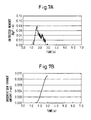
- Figs. 6A, 6B , 7A and 7B illustrate graphs showing a temporal change in orientation change amount of gripper 20 and moment M detected by force detector 14 both in the case where the orientation error of workpiece W2 around X- and Y-axes with respect to workpiece W1 is corrected based on moment M detected by force detector 14 as in the conventional compliance control or force control and in the case where the orientation error of workpiece W2 around X- and Y-axes with respect to workpiece W1 is corrected based on maximum value M' of the moment detected by force detector 14 according to the present invention.
- force control gain G is set to 0.03 (rad/Kgfms) in order to prevent oscillation due to vibration of workpiece W2.
- an oscillation limit is higher than that in the prior art, and therefore, in Figs. 7A and 7B , force control gain G is set to 0.09 (rad/Kgfms), i.e. three times as high as the force control gain in the case of Figs. 6A and 6B .
- rad/Kgfms rad/Kgfms
- the fitting operation is started from the state in which axis 38 of protrusion 24 of workpiece W2 held by gripper 20 and center axis 28 of fitting line 26 of workpiece W1 fixed to table 18 are misaligned with each other by 10 mrad, moment M due to the orientation error of workpiece W2 is generated after 1.3 seconds, and the orientation error is corrected after 1.5 seconds.
- angular velocity command ⁇ is determined from the magnitude of moment M detected at that time by force detector 14 in every control cycle
- the angular velocity command is determined from maximum value M' of the moment detected by force detector 14 during the contact of the workpieces with each other. Therefore, in Figs. 7A, 7B , after 1.7 seconds when moment M becomes maximum, the angular velocity command is calculated from this maximum value M' and continues to be used until 2.8 seconds when moment M detected by force detector 14 becomes zero.
- controller 16 in every control cycle, corrects the operation command for robot arm 12 based on maximum values F', M' of the force and the moment detected by force detector 14 while two workpieces W1, W2 are in contact with each other or force F0 and moment M0 detected by force detector 14 when two workpieces W1, W2 first come into contact with each other, so that the position of gripper 20 and workpiece W2 in the direction perpendicular to the fitting direction and the orientation of gripper 20 and workpiece w2 around the axis perpendicular to the fitting direction are corrected until force F and moment M detected by force detector 14 become less than or equal to predetermined threshold values TF, TM, respectively.
- Force F and moment M exerting on workpiece w2 held by gripper 20 are detected in every control cycle, and force F and moment M thus detected are used only for the purpose of monitoring whether force F and moment M have become less than or equal to the predetermined threshold values TF, TM, respectively.
- data about force F and moment M detected by force detector 14 are not used directly for feedback control. Therefore, even if force detector 14 is accompanied by noises due to the vibration of robot arm 12 or workpiece W2, the operation of correcting the position error and the orientation error of workpiece W2 with respect to workpiece W1 is not substantially affected.
- force control gain G can be set to a larger value than that in the prior art. As a result, an initial error, if any, in workpieces W1, W2 or robot arm 12 can be corrected stably and more quickly than in the prior art.
- the position error is corrected based on force F exerting in the directions of the two axes (X- and Y-axes in the above description) perpendicular to the fitting direction for each component
- the orientation error is corrected based on moment M exerting around the two axes (X- and Y-axes in the above description) perpendicular to the fitting direction for each component.
- the position error and the orientation error are not necessarily corrected for each component as described above.
- velocity command u in X' direction may be determined from force control gain G.
- the resultant moment of moments M X , M Y around X- and Y-axes received by workpiece W2 the instant workpieces W1 and W2 come into contact with each other is designated as MR and the direction of the rotation axis of moment MR is designated as X"
- angular velocity command ⁇ around rotation axis X may be determined.
Abstract
Description
- The present invention relates to a fitting apparatus for fitting two workpieces to each other using a robot while performing compliance control or force control.
- In carrying out assembly using a robot, it is required to position a workpiece in place on a table while at the same time moving another workpiece accurately to the place with the robot. However, between the workpiece held by the robot and the workpiece fixed to the table, there exists a position error and an orientation error, which sometimes adversely affects assembly, or especially, the fitting of the two workpieces by the robot. In order to solve this problem, a fitting apparatus for fitting two workpieces to each other generally uses a RCC (remote center compliance) mechanism in which a spring or a damper is interposed between the robot arm and the robot gripper to thereby provide a mechanically elastic motion of the gripper mounted at the forward end of the robot arm, so that one workpiece held in the gripper can be fitted smoothly with the other workpiece by automatically changing the position and the orientation of the one workpiece held in the gripper even in the presence of some position error or orientation error. Further, as described in Japanese Examined Patent Publication No.
4-43744 6-83976 5-38637 2604929 - In the conventional compliance control or force control, one of the two workpieces to be fitted to each other is held by the gripper of the robot arm and pressed against the other workpiece to thereby carry out the fitting operation, while the force and moment exerting on the workpiece held by the gripper are detected and the operation of the robot arm is controlled and corrected so as to bring the detected force and moment to a target value. In correcting the operation of the robot arm for each control period, the difference between the detected force and the target force and the difference between the detected moment and the target moment are multiplied by a parameter called a force control gain to thereby calculate a command velocity and a command angular velocity for the robot arm. Based on the command velocity and the command angular velocity thus calculated, the workpiece held by the gripper is translated and rotated. Therefore, the force control gain exhibits the force control performance and a larger value of the force control gain can achieve a quicker correction of the position and orientation of the workpiece held by the gripper.
- However, as the force control gain is increased, the vibration of the robot arm and the vibration due to the contact between the workpieces are liable to be amplified and the operation of the robot arm is easily oscillated. Therefore, in the conventional compliance control or force control, the force control gain can be increased only to a value determined by the oscillation limit, and in the system having an initial error in the position and orientation of the workpieces and the robot arm, the error correction requires a vast amount of time.
- Accordingly, it is an object of the present invention to provide a fitting apparatus using the compliance control or force control in which workpieces can be fitted to each other more quickly and more stably than in the prior art.
- In order to achieve the object described above, according to the present invention, a fitting apparatus is provided which includes a robot arm having, at the forward end thereof, a gripper for holding a workpiece, a force detector for detecting a force and moment received by the workpiece held by the gripper, and a controller for controlling an operation of the robot arm, the gripper holding one of two workpieces to be fitted to each other and moving the workpiece in a fitting direction to be fitted to the other of the two workpieces while compliance control or force control is performed so as to correct a position and orientation of the workpiece held by the gripper based on an output of the force detector, wherein the controller includes an operation command generating unit for generating an operation command to fit the two workpieces to each other, and an operation command correcting unit for correcting the operation command generated by the operation command generating unit so as to correct the position of the gripper in a direction perpendicular to the fitting direction and the orientation of the gripper around an axis perpendicular to the fitting direction until the force and moment detected by the force detector become less than or equal to a predetermined threshold value, based on either maximum value of the force and moment detected by the force detector while the two workpieces are in contact with each other or the force and moment detected by the force detector when the two workpieces first come into contact with each other, the controller controlling the operation of the robot arm to fit the two workpieces to each other in accordance with the corrected operation command.
- In the fitting apparatus according to the present invention, the operation command for the robot arm is corrected, in every control cycle of the controller, based on either maximum value of the force and moment detected by the force detector while the two workpieces are in contact with each other or the force and moment detected by the force detector when the two workpieces first come into contact with each other, and the position of the gripper and workpiece in the direction perpendicular to the fitting direction and the orientation of the gripper and workpiece around the axis perpendicular to the fitting direction are corrected until the force and moment detected by the force detector are reduced to or less than the predetermined threshold value. The force and moment of the workpiece held by the gripper are detected in every control cycle, and the force and moment thus detected are used only for monitoring whether or not they are reduced to or less than the predetermined threshold value. Therefore, even if the force detection means is accompanied by noises due to the vibration of the robot arm or workpiece, the correcting operation is not substantially affected, and the force control gain can be set to a larger value than that in the prior art.
- In the fitting apparatus described above, the operation command correcting unit preferably corrects the operation command so as to reduce the force and moment detected by the force detector. For example, the force detector detects the forces exerting in the directions along two axes perpendicular to the fitting direction and perpendicular to each other, and the operation command correcting unit corrects the operation command based on the forces in the directions along the two axes detected by the force detector to thereby correct the position of the gripper in the directions perpendicular to the fitting direction. The force detector detects the moments around the two axes perpendicular to the fitting direction and perpendicular to each other, and the operation command correcting unit corrects the operation command based on the moments around the two axes detected by the force detector to thereby correct the orientation of the gripper around the axes perpendicular to the fitting direction.
- The operation command correcting unit preferably corrects the operation command until the force and moment detected by the force detector are reduced to zero.
- The force detector can be a force sensor.
- The force detector may determine the force and moment received by the workpiece, based on a current value of an actuator for driving the robot arm.
- In the preset application, the term "force control gain" is a constant defined by the following equation.


- According to the present invention, even if the force detection means is accompanied by noises due to the vibration of the robot arm or workpiece, the correcting operation is not affected, and a force control gain can be set to a larger value than that in the prior art, thereby making it possible to correct an initial error, if any in the workpieces or the robot arm, quicker than in the prior art. As a result, quick, stable fitting operation can be carried out.
- The above and other objects, features and advantages of the present invention will be described in more detail below based on preferred embodiments of the present invention with reference to the accompanying drawings, in which:
-
Fig. 1 is a perspective view showing a general configuration of a fitting apparatus according to the present invention; -
Fig. 2 is a function block diagram of the fitting apparatus according to the present invention; -
Fig. 3 is a flowchart showing steps of the fitting operation by the fitting apparatus shown inFigs. 1 and2 ; -
Figs. 4A to 4D are diagrams showing the steps of the fitting operation by the fitting apparatus shown inFigs. 1 and2 ; -
Fig. 5 is a flowchart showing steps of the fitting operation by the fitting apparatus shown inFigs. 1 and2 according to another embodiment; -
Figs. 6A and 6B are graphs showing a temporal change of a moment received by a workpiece and a orientation of the workpiece under conventional compliance control or force control; and -
Figs. 7A and 7B are graphs showing a temporal change of a moment received by a workpiece and an orientation of the workpiece under compliance control or force control employed by the fitting apparatus according to the present invention. - The preferred embodiments of the present invention will be described below with reference to the accompanying drawings.
- First, a general configuration of a
fitting apparatus 10 according to the present invention will be explained with reference toFig. 1 . - The
fitting apparatus 10 includes arobot arm 12 adapted to be able to move around a plurality of axes, aforce detector 14 for detecting a force and a moment, acontroller 16 for controlling an operation ofrobot arm 12, and a table 18 for mounting a workpiece W1 thereon. Agripper 20 adapted to be able to hold and release a workpiece W2 is provided at the forward end ofrobot arm 12. Aclamp unit 22 for fixing workpiece W1 is provided on table 18, so that workpiece W1 to be fitted to workpiece W2 held bygripper 20 can be fixed removably to table 18. -
Force detector 14 is mounted on the wrist ofrobot arm 12 so that force F and moment M received by workpiece W2 held bygripper 20 can be detected. For example,force detector 14 can be a 6-axis force sensor, which is mounted between the forward end ofrobot arm 12 andgripper 20 and adapted to be able to detect forces in directions along three orthogonal axes and moments around three orthogonal axes. However,force detector 14 is not limited to the 6-axis force sensor, but may be any device for estimating the force and the moment received by workpiece W2 held bygripper 20, based on a current value of an actuator (not shown) such as a motor for drivingrobot arm 12. - Workpieces W1, W2 to be fitted to each other may be constituted, for example, by a workpiece W2 having a
cylindrical protrusion 24 and a workpiece W1 formed with acylindrical fitting hole 26 mating withcylindrical protrusion 24. Infitting apparatus 10 shown inFig. 1 , workpieceW2 having protrusion 24 is held bygripper 20 and moved in the fitting direction parallel to acenter axis 28 offitting hole 26 withprotrusion 24 aligned withcenter axis 28 offitting hole 26 of workpiece W1 fixed to table 18, so thatprotrusion 24 of workpiece 2 is inserted intofitting hole 26 of workpiece W1 to thereby fit two workpieces W1, W2 to each other. -
Fig. 2 is a function block diagram offitting apparatus 10 according to the present invention, showing the detail ofcontrol unit 16 used infitting apparatus 10. -
Controller 16, as shown inFig. 2 , includes an operationcommand generating unit 30 for generating an operation command forrobot arm 12 andgripper 20, and an operationcommand correcting unit 32 for correcting, under predetermined conditions, the operation command generated by operationcommand generating unit 30. Operationcommand generating unit 30, in accordance with a program input in advance or the like, generates operation commands, specifically a velocity command and an angular velocity command, forrobot arm 12 and gripper 20 thereof so as to makegripper 20 hold one workpiece W2 included in two workpieces W1, W2 to be fitted to each other at a predetermined place and fit it to the other workpiece W1 fixed at a predetermined place on table 18. Operationcommand correcting unit 32 is configured of a forcecontrol gain unit 34 and a force andmoment holding unit 36; - Force and
moment holding unit 36 is implemented by a storage unit such as a RAM and adapted to store or hold maximum values F', M' of force F and moment M detected byforce detector 14 while workpiece W2 held bygripper 20 and workpiece W1 fixed to table 18 are in contact with each other, and values F0, M0 of force F and moment M detected byforce detector 14 when workpiece W2 held bygripper 20 and workpiece W1 fixed to table 18 first come into contact with each other. Forcecontrol gain unit 34, upon input of the difference between forces F', F0 and moments M', M0 held in force andmoment holding unit 36 and a target force Fd and a target moment Md to be detected byforce detector 14 when workpieces W1, W2 are fitted to each other, multiplies the input by a force control gain G to thereby output a velocity command correction amount υc and an angular velocity command correction amount ωc for causingrobot arm 12 andgripper 20 to perform the motion required to make force F and moment M detected byforce detector 14 approach target force Fd and target moment Md, respectively. - Operation
command correcting unit 32 corrects velocity command u and angular velocity command ω by adding velocity command correction amount υc and angular velocity command correction amount ωc output from forcecontrol gain unit 34 to velocity command u and angular velocity command ω generated by operationcommand generating unit 30, respectively, and causesrobot arm 12 and gripper 20 thereof to move based on corrected velocity command υ' and corrected angular velocity command ω'. The correction of the operation commands by operationcommand correcting unit 32 is continued until force F and moment M detected byforce detector 14 are reduced to less than or equal to predetermined threshold values TF, TM, respectively. - Next, the operation of
fitting apparatus 10 shown inFigs. 1 and2 will be described with reference toFigs. 3 to 5 . In the following description, a Z-axis represents a direction ofcenter axis 28 offitting hole 26 of workpiece W1 fixed to table 18, and X- and Y-axes represent directions perpendicular to each other in a plane perpendicular to the Z-axis. - First, one workpiece w1 included in workpiece pair W1, W2 to be fitted to each other is fixed at a predetermined place on table 18 by the operator or another robot. In accordance with the operation command generated by operation
command generating unit 30 based on a predetermined program or the like,robot arm 12 holds, bygripper 20 thereof, mating workpiece W2 arranged at a predetermined place, and moves workpiece W2 to a place in opposed relation to workpiece W1 fixed to table 18 so as to align the axis ofprotrusion 24 of workpiece w2 held bygripper 20 withcenter axis 28 offitting hole 26 of workpiece W1 fixed to table 18.Robot arm 12 further moves workpiece W2 in the fitting direction (i.e. Z-axis direction) parallel to centeraxis 28 offitting hole 26 of workpiece W1 to contact it with workpiece W1 on table 18 (step S100). Please note that the operation commands include a velocity command υ(υX, υY, υZ) for translatinggripper 20 along the directions of the X-, Y- and Z-axes and an angular velocity command ω(ωW, ωP, ωR) for rotatinggripper 20 around the X-, Y- and Z- axes and that the components of velocity command u and angular velocity command ω other than the fitting direction component of the velocity command become zero, i.e. υx=0, υy=0, ωW=0, ωP=0 and ωR=0. - In the case where workpiece W1 and workpiece W2 are arranged such that
center axis 28 offitting hole 26 of workpiece W1 fixed to table 18 is accurately aligned with the axis ofprotrusion 24 of workpiece W2 held bygripper 20,protrusion 24 of workpiece W2 will be smoothly inserted intofitting hole 26 of workpiece W1. Specifically, the components of force F(Fx, FY, Fz) and moment M(Mx, MY, Mz) exerting on workpiece W2 during the fitting operation other than the fitting direction component become zero (i.e. Fx=0, FY=0, MX=0, MY=0, Mz=0). Therefore, target Fd(Fdx, FdY, Fdz) and target moment Md(Mdx, MdY, Mdz) to be exerted on workpiece W2 during the fitting operation are determined so that all the components of target force Fd (FdX, FdY, FdZ) and target moment Md (MdX, MdY, MdZ) other than the fitting direction component become zero (i.e. FdX=0, FdY=0, MdX=0, MdY=0, MdZ=0). - However, position and orientation errors occur when workpiece W1 is fixed to table 18 and workpiece W2 is held by
gripper 20, and the fitting operation is often performed whilecenter axis 28 offitting hole 26 of workpiece W1 fixed to table 18 is not accurately aligned with the axis ofprotrusion 24 of workpiece w2 held bygripper 20. When workpiece W2 held bygripper 20 comes into contact with workpiece W1 fixed to table 18 in such a case, some force F and moment M exert on workpiece W2 held by gripper 20 (step S102). For example, in the case where, as shown inFig. 4A ,axis 38 ofprotrusion 24 of workpiece W2 held bygripper 20 is inclined with respect tocenter axis 28 offitting hole 26 of workpiece W1 fixed to table 18, when two workpieces W1, W2 come into contact with each other, forces FX and FY in the directions perpendicular to the fitting direction and moments MX, MY around the axes perpendicular to the fitting direction exert on workpiece W2 held bygripper 20, as shown inFig. 4B . Onceforce detector 14 detects force F and moment M received by workpiece W2,controller 16 controls the operation ofrobot arm 12 andgripper 20 such that force F and moment M detected byforce detector 14 approach target force Fd and target moment Md, respectively. - In
fitting apparatus 10 according to the present invention, the maximum values of force F(FX, FY, FZ) and moment M(MX, MY, MZ) detected byforce detector 14 while workpiece W1 fixed to table 18 and workpiece W2 held bygripper 20 are in contact with each other are stored or held in force andmoment holding unit 36. In every control cycle, force andmoment holding unit 36 compares the components of force F(Fx, Fy, Fz) and moment M (MX, MY, Mz) detected byforce detector 14 with the corresponding components of force F' (F'x, F'Y, F'z) and moment M' (M'x, M'Y, M'z) stored or held in force andmoment holding unit 36. When any component of force F(Fx, FY, Fz) and moment M(MX, MY, Mz) detected byforce detector 14 is larger than the corresponding component of force F'(F'x, F'Y, F'z) and moment M'(M'x, M'Y, M'Z) stored or held at that time in force andmoment holding unit 36, the stored or held value of the component of force F' (F'x, F'Y, F'z) and moment M'(M'X, M'Y, M'z) is updated to the value of the corresponding component of force F(Fx, FY, Fz) and moment M(Mx, MY, Mz) detected byforce detector 14, and stored or held. - Regarding Z-axis velocity command υZ, like in the conventional compliance control or force control, operation
command correcting unit 32 multiplies the difference between Z-axis force FZ detected byforce detector 14 and Z-axis target force FdZ by force control gain Gz to thereby calculate a velocity command correction value υcZ, and adds calculated velocity command correction value υcZ to Z-axis velocity command υZ generated by operationcommand generating unit 30 to thereby correct Z-axis velocity command υZ. Specifically, in accordance with following equation (1), a corrected Z-axis velocity command υ'Z is determined.
- On the other hand,
protrusion 24 of workpiece W2 andfitting hole 26 of workpiece W1 are cylindrical and the rotation around Z-axis is meaningless. Therefore, angular velocity command ωR around Z-axis and corrected angular velocity ω'R around Z-axis are not required to be determined. However, in the case whereprotrusion 24 of workpiece W2 andfitting hole 26 of workpiece W1 are not cylindrical, like in the conventional compliance control or force control, corrected angular velocity ω'R around Z-axis is determined according to the following equation.
where GR is the force control gain for the moment around Z-axis. - Regarding X-axis velocity command υX, Y-axis velocity command υY, angular velocity command around X-axis ωW and angular velocity command around Y-axis ωP, operation
command correcting unit 32 multiplies the difference between maximum values F', M' of the force and moment stored or held in force andmoment holding unit 36 and target force Fd and target moment Md by force control gain G to thereby calculate velocity command correction amounts υcX, υcY and angular velocity command correction amounts ωCW ωcP, and adds calculated velocity command correction amountsυcX, υcY and angular velocity command correction amountsωCW, ωcP to X-axis velocity command υX, Y-axis velocity command υY, angular velocity command around X-axis ωW and angular velocity command around Y-axis ωP generated by operationcommand generating unit 30, respectively, to thereby correct X-axis velocity command υX, Y-axis velocity command υY, angular velocity command around X-axis ωW and angular velocity command around X-axis ωP, respectively. Taking into consideration the fact that X-axis target force Fdx, Y -axis target force FdY, moment around X-axis MdX and moment around Y-axis MdY are all zero, corrected X-axis velocity command υ'x, corrected Y-axis velocity command υ'Y, corrected angular velocity command around X-axis ω'w and corrected angular velocity command around Y-axis ω'P can be determined from following Equations (2) to (5).


where GX, GY represent the force control gain of the X-axis force and the force control gain of the Y-axis force, respectively, and Gw, Gp represent the force control gain of the moment around X-axis and the force control gain of the moment around Y-axis, respectively. - The fitting operation is an operation of moving
gripper 20 and workpiece W2 only in the fitting direction, i.e. along Z-axis, and in the fitting operation, X-axis velocity command υX, Y-axis velocity command υY, angular velocity command around X-axis ωW and angular velocity command around Y-axis ωP are all zero. Therefore, operation command correction amounts υcX, υcY, ωcW, ωcp determined by operationcommand correcting unit 32 become corrected X-axis velocity command υ'X, corrected Y-axis velocity command υ'Y, corrected angular velocity command around X-axis ω'W and corrected angular velocity command around Y-axis ω'P, respectively. Thus, operationcommand correcting unit 32 determines υ'X, υ'Y, ω'W, ω'P as the X-axis velocity command, the Y-axis velocity command, the angular velocity commands around X-axis and the angular velocity command around Y-axis, respectively, by multiplying maximum values F', M' of the force and the moment stored or held in force andmoment holding unit 36 by force control gain G. -
Controller 16, as shown inFig. 4C , operatesrobot arm 12 andgripper 20, based on corrected X-axis velocity command υ'X, corrected Y-axis velocity command υ'Y, corrected Z-axis velocity command υ'Z, corrected angular velocity command around X-axis ω'W and corrected angular velocity command around Y-axis ω'P thus determined, and corrects the position and orientation ofgripper 20 and workpiece W2 (step S104). - Next, X- and Y-axis forces FX, FY and moments MX, MY around X- and Y-axes detected by
force detector 14 are compared with predetermined threshold values TFX, TFY, TMX, TMY, respectively, in every control cycle, and if any of the former values is larger than a predetermined corresponding threshold value, the process of step S104 is repeated in every control cycle and the correction of the position and orientation ofgripper 20 and workpiece W2 is continued until all of FX, FY, MX, MY satisfy following Equation (6) (step S106).
where threshold values TFX, TFY are ones associated with X-axis force FX and Y-axis force FY detected, respectively, and threshold values TMX, TMY are ones associated with moment Mx around X-axis and moment MY around Y-axis, respectively. - On the other hand, if all of forces FX, FY and moments MX, MY detected by
force detector 14 become less than or equal to predetermined threshold values TFX, TFY, TMX, TMY, respectively, and Equation (6) comes to be satisfied, it is judged that the error correction of the position and orientation ofgripper 20 and workpiece W2 has been completed (step S108). When the correction of the position and orientation ofgripper 20 and workpiece W2 has been completed,axis 38 ofprotrusion 24 of workpiece W2 held bygripper 20 is aligned withcenter axis 28 offitting hole 26 of workpiece W1 fixed to table 18. Therefore, by movinggripper 20 and workpiece W2 in the fitting direction while keeping this position and orientation,protrusion 24 of workpiece W2 held bygripper 20 can be smoothly inserted intofitting hole 26 of workpiece W1 fixed to table 18, as shown inFig. 4D , thereby completing the fitting operation (step S110). - In the description of the above-mentioned operation of
fitting apparatus 10 according to the present invention, maximum values F' (F'x, F'Y, F'z) and M'(M'X, M'Y, M'z') of force F and moment M detected byforce detector 14 while workpiece W1 and workpiece W2 are in contact with each other are stored or held in force andmoment holding unit 36. However, alternatively, force andmoment holding unit 36 may store or hold force F0(F0x F0Y, F0z) and moment M0(M0x, M0Y, M0z) detected byforce detector 14 when workpieces W1 and W2 first come into contact with each other. When two workpieces W1, W2 are not in contact with each other, force F and moment M are substantially zero. Therefore, by detecting that components of force F (FX, FY, FZ) and moment M (MX, MY, MZ) detected byforce detector 14 has exceeded a predetermined value, the contact between the two workpieces W1, W2 can be detected. -
Fig. 5 shows operation steps in the case where, as described above, force F0 and moment M0 detected byforce detector 14 when workpieces W1, W2 first come into contact with each other are stored or held in force andmoment holding unit 36. The operation steps shown inFig. 5 are different from those shown inFig. 3 in that step S104 of the operation steps shown inFig. 3 is replaced by step S112, while the other steps remain the same. - Once workpieces W1, W2 come into contact with each other in step S100 and force F and moment M are exerted on workpiece W2 held by
gripper 20, force F and moment M exerted on workpiece W2 are detected by force detector 14 (step S102). Force andmoment holding unit 36 stores and then continues to hold force F0(F0X, F0Y, F0Z) and moment M0(M0X, M0Y, M0Z) detected byforce detector 14 when workpieces W1 and W2 first come into contact with each other. - Operation
command correcting unit 32, as in step S104, corrects Z-axis velocity command υZ generated by operationcommand generating unit 30, based on the difference between Z-axis force FZ detected byforce detector 14 and Z-axis target force FdZ, and determines corrected Z-axis velocity command υ'Z in accordance with Equation (1). Rotation around Z-axis is meaningless becauseprotrusion 24 of workpiece W2 andfitting hole 26 of workpiece W1 are cylindrical. Therefore, angular velocity command ωR around Z-axis and corrected angular velocity ω'R around Z-axis are not required to be determined. However, whenprotrusion 24 of workpiece W2 andfitting hole 26 of workpiece W1 are not cylindrical, corrected angular velocity ω'R around Z-axis may be determined in the same way as in the steps shown inFig. 3 . - On the other hand, regarding X-axis velocity command υX, Y-axis velocity command υY, angular velocity command around X-axis ωW and angular velocity command around Y-axis ωP, operation
command correcting unit 32 multiplies the difference between force F0 and moment M0 stored or held in force andmoment holding unit 36 and target force Fd and target moment Md by force control gain G to thereby calculate operation command correction amounts υcX, υcY, ωcW, ωcp, and adds operation command correction amountsυcX, υcY, ωcW, ωcP thus determined by the calculation to X-axis velocity command υX, Y-axis velocity command υY, angular velocity command around X-axis ωW and angular velocity command around Y-axis ωP generated by operationcommand generating unit 30, respectively, to thereby correct X-axis velocity command υX, Y-axis velocity command υY, angular velocity command around X-axis ωW and angular velocity command around Y-axis ωP. Taking into consideration the fact that X- and Y-axis target forces FdX, FdY and moments MdX, MdY around X- and Y-axes are all zero, corrected X-axis velocity command υ'X, corrected Y-axis velocity command υ'Y, corrected angular velocity command around X-axis ω'W and corrected angular velocity command around Y-axis ω'P can be determined from following Equations (2') to (5').


where GX, GY represent a force control gain of the X-axis force and a force control gain of the Y-axis force, respectively, and GW, Gp represent a force control gain of the moment around X-axis and a force control gain of the moment around Y-axis, respectively. - Further, since X-axis velocity command υX, Y-axis velocity command υY, angular velocity command around X-axis ωW and angular velocity command around Y-axis ωP are all zero, operation command correction amounts υcX, υcY, ωcW, ωcP determined by operation
command correcting unit 32 are corrected X-axis velocity command υ'X, corrected Y-axis velocity command υ'Y, corrected angular velocity command around X-axis ω'W and corrected angular velocity command around Y-axis ω'P, respectively. Therefore, it can be said that operationcommand correcting unit 32 multiplies force F0 and moment M0 stored or held in force andmoment holding unit 36 by force control gain G to thereby determine υ'X, υ'Y, ω'W, ω'P as X- and Y-axis velocity commands and angular velocity commands around X- and Y-axes, respectively. -
Controller 16 operatesrobot arm 12 andgripper 20 thereof based on corrected X-axis velocity command υ'X, corrected Y-axis velocity command υ'Y, corrected angular velocity command around X-axis ω'W and corrected angular velocity command around Y-axis ω'P thus determined to thereby correct the position and orientation ofgripper 20 and workpiece W2 (step S112). - Next, in every control cycle, force F and moment M received by workpiece W2 are detected by
force detector 14, and X- and Y-axis forces FX, FY and moments around X- and Y-axes MX and MY thus detected are compared with predetermined threshold values TFX, TFY, TMX, TMY, respectively. If any of them is larger than the corresponding one of the predetermined threshold values, step S112 is repeated and the correction of the position and orientation ofgripper 20 and workpiece W2 is continued until all of FX, FY, MX, MY satisfy Equation (6), in every control cycle (step S106). - On the other hand, if all of forces FX, FY and moments MX, MY detected by
force detector 14 become less than or equal to predetermined threshold values TFX, TFY, TMX, TMY, respectively, and Equation (6) comes to be satisfied, it is judged that the error correction of the position and orientation ofgripper 20 and workpiece W2 has been completed (step S108). When the correction of the position and orientation ofgripper 20 and workpiece W2 has been completed,axis 38 ofprotrusion 24 of workpiece W2 held bygripper 20 is aligned withcenter axis 28 offitting hole 26 of workpiece W1 fixed to table 18. Therefore, by movinggripper 20 in the fitting direction while keeping this position and orientation,protrusion 24 of workpiece W2 held bygripper 20 can be smoothly inserted intofitting hole 26 of workpiece W1 fixed to table 18, thereby completing the fitting operation (step S110). - Next, effects of the present invention will be described taking the case as an example in which workpieces W1, W2 have an orientation error, with reference to
Figs. 6A, 6B ,7A and 7B . -
Figs. 6A, 6B ,7A and 7B illustrate graphs showing a temporal change in orientation change amount ofgripper 20 and moment M detected byforce detector 14 both in the case where the orientation error of workpiece W2 around X- and Y-axes with respect to workpiece W1 is corrected based on moment M detected byforce detector 14 as in the conventional compliance control or force control and in the case where the orientation error of workpiece W2 around X- and Y-axes with respect to workpiece W1 is corrected based on maximum value M' of the moment detected byforce detector 14 according to the present invention. - In
Figs. 6A and 6B showing the prior art, force control gain G is set to 0.03 (rad/Kgfms) in order to prevent oscillation due to vibration of workpiece W2. On the other hand, according to the present invention, an oscillation limit is higher than that in the prior art, and therefore, inFigs. 7A and 7B , force control gain G is set to 0.09 (rad/Kgfms), i.e. three times as high as the force control gain in the case ofFigs. 6A and 6B . Also, in both cases shown inFigs. 6A, 6B and7A, 7B , the fitting operation is started from the state in whichaxis 38 ofprotrusion 24 of workpiece W2 held bygripper 20 andcenter axis 28 offitting line 26 of workpiece W1 fixed to table 18 are misaligned with each other by 10 mrad, moment M due to the orientation error of workpiece W2 is generated after 1.3 seconds, and the orientation error is corrected after 1.5 seconds. - In
Figs. 6A, 6B showing the prior art, angular velocity command ω is determined from the magnitude of moment M detected at that time byforce detector 14 in every control cycle, while inFigs. 7A, 7B showing the present invention, the angular velocity command is determined from maximum value M' of the moment detected byforce detector 14 during the contact of the workpieces with each other. Therefore, inFigs. 7A, 7B , after 1.7 seconds when moment M becomes maximum, the angular velocity command is calculated from this maximum value M' and continues to be used until 2.8 seconds when moment M detected byforce detector 14 becomes zero. - Thus, from
Figs. 7A and 7B showing the present invention, it can be understood that as the result of setting force control gain G at three times as large as the value for the prior art shown inFigs. 6A and 6B , the correction of the orientation error of workpiece W2 is completed in about one third of the time required in the case shown inFigs. 6A and 6B . - In
fitting apparatus 10 according to the present invention,controller 16, in every control cycle, corrects the operation command forrobot arm 12 based on maximum values F', M' of the force and the moment detected byforce detector 14 while two workpieces W1, W2 are in contact with each other or force F0 and moment M0 detected byforce detector 14 when two workpieces W1, W2 first come into contact with each other, so that the position ofgripper 20 and workpiece W2 in the direction perpendicular to the fitting direction and the orientation ofgripper 20 and workpiece w2 around the axis perpendicular to the fitting direction are corrected until force F and moment M detected byforce detector 14 become less than or equal to predetermined threshold values TF, TM, respectively. Force F and moment M exerting on workpiece w2 held bygripper 20 are detected in every control cycle, and force F and moment M thus detected are used only for the purpose of monitoring whether force F and moment M have become less than or equal to the predetermined threshold values TF, TM, respectively. Specifically, data about force F and moment M detected byforce detector 14 are not used directly for feedback control. Therefore, even ifforce detector 14 is accompanied by noises due to the vibration ofrobot arm 12 or workpiece W2, the operation of correcting the position error and the orientation error of workpiece W2 with respect to workpiece W1 is not substantially affected. Thus, force control gain G can be set to a larger value than that in the prior art. As a result, an initial error, if any, in workpieces W1, W2 orrobot arm 12 can be corrected stably and more quickly than in the prior art. - Although the present invention has been described above based on the embodiments shown in the drawings, it should not be limited to those embodiments. For example, in the foregoing description, the position error is corrected based on force F exerting in the directions of the two axes (X- and Y-axes in the above description) perpendicular to the fitting direction for each component, and the orientation error is corrected based on moment M exerting around the two axes (X- and Y-axes in the above description) perpendicular to the fitting direction for each component. However, the position error and the orientation error are not necessarily corrected for each component as described above. As an alternative, assuming that the resultant force of forces Fx, FY received by workpiece W2 in the X- and Y-axis directions the instant workpieces W1 and W2 come into contact with each other is designated as FR and the direction of FR is designated as X', velocity command u in X' direction may be determined from force control gain G. At the same time, assuming that the resultant moment of moments MX, MY around X- and Y-axes received by workpiece W2 the instant workpieces W1 and W2 come into contact with each other is designated as MR and the direction of the rotation axis of moment MR is designated as X", angular velocity command ω around rotation axis X" may be determined.
Claims (6)
- A fitting apparatus (10) comprising a robot arm (12) having, at the forward end thereof, a gripper (20) for holding a workpiece (W2), a force detector (14) for detecting a force and moment received by said workpiece (W2) held by said gripper (20), and a controller (16) for controlling an operation of said robot arm (12), said gripper (20) holding one (W2) of two workpieces (W1, W2) to be fitted to each other and moving said workpiece (W2) in a fitting direction to be fitted to the other (W1) of said two workpieces (W1, W2) while compliance control or force control is performed so as to correct a position and orientation of said workpiece (W2) held by said gripper (20) based on an output of said force detector (14), said fitting apparatus characterized in that:said controller (16) includes an operation command generating unit (30) for generating an operation command to fit said two workpieces (W1, W2) to each other, and an operation command correcting unit (32) for correcting the operation command generated by said operation command generating unit (30) so as to correct the position of said gripper (20) in a direction perpendicular to the fitting direction and the orientation of said gripper (20) around an axis perpendicular to the fitting direction until the force and moment detected by said force detector (14) become less than or equal to a predetermined threshold value, based on either maximum values of the force and moment detected by said force detector (14) while said two workpieces (W1, W2) are in contact with each other or the force and moment detected by said force detector (14) when said two workpieces (W1, W2) first come into contact with each other, said controller (16) controlling the operation of said robot arm (12) to fit said two workpieces (W1, W2) with each other in accordance with the corrected operation command.
- The fitting apparatus according to claim 1, wherein said operation command correcting unit (32) corrects the operation command so as to reduce the force and moment detected by said force detector (14).
- The fitting apparatus according to claim 2, wherein said force detector (14) detects the force exerting in the directions along two axes perpendicular to the fitting direction and perpendicular to each other, and wherein said operation command correcting unit (32) corrects the operation command based on the forces in the directions along the two axes detected by said force detector (14) to thereby correct the position of said gripper (20) in the directions perpendicular to the fitting direction.
- The fitting apparatus according to claim 2, wherein said force detector (14) detects the moment around the two axes perpendicular to the fitting direction and perpendicular to each other, and wherein said operation command correcting unit (32) corrects the operation command based on the moments around the two axes detected by said force detector (14) to thereby correct the orientation of said gripper (20) around the two axes perpendicular to the fitting direction.
- The fitting apparatus according to claim 1, wherein said force detector (14) comprises a force sensor.
- The fitting apparatus according to any one of claims 1 to 5, wherein said force detector (14) determines the force and moment received by said workpiece (W2), based on a current value of an actuator for driving said robot arm (12).
Applications Claiming Priority (1)
| Application Number | Priority Date | Filing Date | Title |
|---|---|---|---|
| JP2007157333A JP4271249B2 (en) | 2007-06-14 | 2007-06-14 | Mating device |
Publications (2)
| Publication Number | Publication Date |
|---|---|
| EP2002945A1 true EP2002945A1 (en) | 2008-12-17 |
| EP2002945B1 EP2002945B1 (en) | 2011-07-27 |
Family
ID=39705294
Family Applications (1)
| Application Number | Title | Priority Date | Filing Date |
|---|---|---|---|
| EP08010707A Active EP2002945B1 (en) | 2007-06-14 | 2008-06-12 | Fitting apparatus for fitting two workpieces to each other |
Country Status (4)
| Country | Link |
|---|---|
| US (1) | US8369983B2 (en) |
| EP (1) | EP2002945B1 (en) |
| JP (1) | JP4271249B2 (en) |
| CN (1) | CN101323111B (en) |
Cited By (6)
| Publication number | Priority date | Publication date | Assignee | Title |
|---|---|---|---|---|
| US8424182B2 (en) | 2010-03-18 | 2013-04-23 | Fanuc Corporation | Fitting device using robot |
| WO2015090652A1 (en) * | 2013-12-18 | 2015-06-25 | Etel S.A. | Positioning device |
| EP2808133A3 (en) * | 2013-05-31 | 2016-06-15 | Kabushiki Kaisha Yaskawa Denki | Robot system and method for producing to-be-processed material |
| WO2018197292A1 (en) * | 2017-04-23 | 2018-11-01 | Franka Emika Gmbh | Device and method for the electrical testing of an electrical component |
| WO2018197298A1 (en) * | 2017-04-23 | 2018-11-01 | Franka Emika Gmbh | Device and method for the electrical testing of an electrical component |
| CN110621446A (en) * | 2017-05-19 | 2019-12-27 | 川崎重工业株式会社 | Robot system and control method for robot system |
Families Citing this family (50)
| Publication number | Priority date | Publication date | Assignee | Title |
|---|---|---|---|---|
| US9008836B2 (en) * | 2007-01-09 | 2015-04-14 | Abb Inc. | Method and system for robotic assembly parameter optimization |
| JP2008302449A (en) * | 2007-06-06 | 2008-12-18 | Fanuc Ltd | Robot control device |
| EP2271465A1 (en) * | 2008-03-31 | 2011-01-12 | Abb Research | Robot parts assembly on a workpiece moving on an assembly line |
| JP4598849B2 (en) * | 2008-09-03 | 2010-12-15 | ファナック株式会社 | Fitting device for correcting clogged fitting |
| US8286320B2 (en) * | 2008-09-18 | 2012-10-16 | Automatic Handling International | Apparatus and method for the robotic plugging/unplugging of rolls |
| JP5353500B2 (en) | 2009-07-08 | 2013-11-27 | 株式会社安川電機 | robot |
| EP2465016A1 (en) * | 2009-08-14 | 2012-06-20 | ABB Technology AG | An industrial robot and a method for adjusting a robot program |
| JP5685027B2 (en) | 2010-09-07 | 2015-03-18 | キヤノン株式会社 | Information processing apparatus, object gripping system, robot system, information processing method, object gripping method, and program |
| DE102010052396A1 (en) * | 2010-11-24 | 2012-05-24 | Kuka Roboter Gmbh | Method and device for controlling a peripheral component of a robot system |
| DE102011006679B4 (en) * | 2011-03-16 | 2018-07-12 | Ferrobotics Compliant Robot Technology Gmbh | Active handling device and method for contact tasks |
| EP2746000A4 (en) * | 2011-08-19 | 2015-08-19 | Yaskawa Denki Seisakusho Kk | Robot system, robot, and robot control device |
| JP2013136141A (en) * | 2011-11-30 | 2013-07-11 | Canon Inc | Grip apparatus, robot apparatus and method for controlling grip apparatus |
| KR101389244B1 (en) * | 2013-04-18 | 2014-04-24 | 재단법인대구경북과학기술원 | Robot for managing of structure and method controling thereof |
| JP6380828B2 (en) * | 2014-03-07 | 2018-08-29 | セイコーエプソン株式会社 | Robot, robot system, control device, and control method |
| WO2015142798A1 (en) * | 2014-03-17 | 2015-09-24 | Intuitive Surgical Operations, Inc. | Methods and devices for tele-surgical table registration |
| JP2016028227A (en) * | 2014-07-08 | 2016-02-25 | ファナック株式会社 | Inspection system for inspecting object by utilizing force sensor |
| CN105382839A (en) * | 2014-08-25 | 2016-03-09 | 精工爱普生株式会社 | Robot and robot system |
| DE112016002431T8 (en) * | 2015-05-29 | 2018-04-05 | Abb Schweiz Ag | Method and system for robotic adaptive production |
| JP6592969B2 (en) * | 2015-06-02 | 2019-10-23 | セイコーエプソン株式会社 | Mating method |
| KR102015522B1 (en) * | 2015-08-25 | 2019-08-28 | 카와사키 주코교 카부시키 카이샤 | Robot system and its operation method |
| JP6665450B2 (en) * | 2015-08-31 | 2020-03-13 | セイコーエプソン株式会社 | Robot, control device, and robot system |
| KR20180015774A (en) * | 2015-09-25 | 2018-02-14 | 두산로보틱스 주식회사 | Method and apparatus for controlling robot |
| JP2017159426A (en) | 2016-03-11 | 2017-09-14 | セイコーエプソン株式会社 | Robot control device, robot, and robot system |
| JP6746990B2 (en) * | 2016-03-18 | 2020-08-26 | セイコーエプソン株式会社 | Robot controller and robot system |
| JP2019514706A (en) * | 2016-04-24 | 2019-06-06 | フランカ エミカ ゲーエムベーハーFRANKA EMIKA GmbH | Method of inserting an object into an object receiving area using a robot manipulator |
| WO2017186636A1 (en) | 2016-04-24 | 2017-11-02 | Haddadin Beteiligungs UG (haftungsbeschränkt) | Method for controlling a robot manipulator for screwing in a screw |
| JP6490032B2 (en) * | 2016-08-10 | 2019-03-27 | ファナック株式会社 | Robot controller for assembly robot |
| US10213925B2 (en) | 2016-09-09 | 2019-02-26 | The Board Of Trustees Of The Leland Stanford Junior University | Workpiece contact state estimating device and workpiece contact state estimation method |
| JP7314475B2 (en) * | 2016-11-11 | 2023-07-26 | セイコーエプソン株式会社 | ROBOT CONTROL DEVICE AND ROBOT CONTROL METHOD |
| JP6457005B2 (en) * | 2017-03-30 | 2019-01-23 | 本田技研工業株式会社 | Position estimation method and gripping method |
| CN108972572B (en) * | 2017-05-31 | 2022-10-28 | 精工爱普生株式会社 | Control device, robot, and control method |
| JP6806036B2 (en) * | 2017-11-08 | 2021-01-06 | 新東工業株式会社 | Main mold and core fitting device, and main mold and core fitting method |
| JP2019160973A (en) * | 2018-03-12 | 2019-09-19 | オムロン株式会社 | Component insertion device, component insertion method, and program |
| JP7135408B2 (en) * | 2018-04-26 | 2022-09-13 | セイコーエプソン株式会社 | Robot controller and robot system |
| JP7131087B2 (en) * | 2018-05-31 | 2022-09-06 | セイコーエプソン株式会社 | ROBOT SYSTEM CONTROL METHOD AND ROBOT SYSTEM |
| JP7028092B2 (en) * | 2018-07-13 | 2022-03-02 | オムロン株式会社 | Gripping posture evaluation device and gripping posture evaluation program |
| JP7218538B2 (en) * | 2018-10-17 | 2023-02-07 | 京セラドキュメントソリューションズ株式会社 | Assembly equipment and structure manufacturing method |
| JP7092307B2 (en) * | 2019-02-01 | 2022-06-28 | 三菱電機株式会社 | Work discrimination device and work discrimination method |
| US11426874B2 (en) * | 2019-04-30 | 2022-08-30 | Flexiv Ltd. | Robot-based insertion mounting of workpieces |
| JP7239399B2 (en) * | 2019-06-19 | 2023-03-14 | ファナック株式会社 | Adjustment support device |
| CN112388264A (en) * | 2019-08-15 | 2021-02-23 | 华南理工大学 | Hole searching method and hole searching device |
| JP2021030364A (en) * | 2019-08-23 | 2021-03-01 | ファナック株式会社 | Robot control device |
| US11701776B2 (en) * | 2019-10-25 | 2023-07-18 | Dexterity, Inc. | Robotic kitting machine |
| JP7230779B2 (en) * | 2019-11-12 | 2023-03-01 | トヨタ自動車株式会社 | How to use the robot hand |
| US11318611B2 (en) | 2020-04-14 | 2022-05-03 | Fanuc Corporation | Multi center impedance control |
| WO2022004371A1 (en) * | 2020-07-03 | 2022-01-06 | 住友重機械工業株式会社 | Operation method, robot system, control device, teaching method, and program |
| US11833666B2 (en) * | 2020-10-28 | 2023-12-05 | Shanghai Flexiv Robotics Technology Co., Ltd. | Method for assembling an operating member and an adapting member by a robot, robot, and controller |
| JP2022073012A (en) * | 2020-10-30 | 2022-05-17 | セイコーエプソン株式会社 | Robot control method and robot system |
| CN114749887A (en) * | 2021-10-12 | 2022-07-15 | 精进百思特电动(上海)有限公司 | Gear assembling method and device |
| JP2023132975A (en) * | 2022-03-11 | 2023-09-22 | オムロン株式会社 | Robot system and control method of the same |
Citations (5)
| Publication number | Priority date | Publication date | Assignee | Title |
|---|---|---|---|---|
| US5441437A (en) * | 1993-02-18 | 1995-08-15 | Hulstedt; Bryan A. | Compliant constant-force follower device for surface finishing tool |
| EP0901054A1 (en) * | 1997-01-27 | 1999-03-10 | Fanuc Ltd | Method and system for controlling robot |
| EP1052072A1 (en) * | 1997-10-22 | 2000-11-15 | Fanuc Ltd. | Force controlling robot and fitting/drawing method using the force controlling robot |
| EP1112805A2 (en) * | 1999-12-27 | 2001-07-04 | Kawasaki Jukogyo Kabushiki Kaisha | Method and apparatus for automatic position-finding assembling |
| US20050113971A1 (en) | 2003-11-24 | 2005-05-26 | Hui Zhang | Industrial robot with controlled flexibility and simulated force for automated assembly |
Family Cites Families (7)
| Publication number | Priority date | Publication date | Assignee | Title |
|---|---|---|---|---|
| US3893217A (en) * | 1974-12-13 | 1975-07-08 | Bendix Corp | System and method for automatic insertion of pins in holes |
| JPH0683976B2 (en) | 1988-03-15 | 1994-10-26 | インターナシヨナル・ビジネス・マシーンズ・コーポレーシヨン | Compliance control method |
| JPH0538637A (en) | 1991-08-02 | 1993-02-19 | Fujitsu Ltd | Parts inserting device |
| JP2604929B2 (en) | 1991-12-03 | 1997-04-30 | 山武ハネウエル株式会社 | Robot control device |
| JPH06126665A (en) | 1992-10-14 | 1994-05-10 | Fujitsu Ltd | Robot dislocation compensating method and device |
| JPH071260A (en) | 1993-06-15 | 1995-01-06 | Nippon Steel Corp | Automatic fitting-in method |
| DE69736348T2 (en) * | 1996-10-24 | 2006-11-30 | Fanuc Ltd. | ROBOT FUEL CONTROL SYSTEM WITH VISUAL SENSOR FOR COMMUNICATION WORK |
-
2007
- 2007-06-14 JP JP2007157333A patent/JP4271249B2/en active Active
-
2008
- 2008-06-12 EP EP08010707A patent/EP2002945B1/en active Active
- 2008-06-12 CN CN2008101256217A patent/CN101323111B/en active Active
- 2008-06-13 US US12/138,995 patent/US8369983B2/en active Active
Patent Citations (5)
| Publication number | Priority date | Publication date | Assignee | Title |
|---|---|---|---|---|
| US5441437A (en) * | 1993-02-18 | 1995-08-15 | Hulstedt; Bryan A. | Compliant constant-force follower device for surface finishing tool |
| EP0901054A1 (en) * | 1997-01-27 | 1999-03-10 | Fanuc Ltd | Method and system for controlling robot |
| EP1052072A1 (en) * | 1997-10-22 | 2000-11-15 | Fanuc Ltd. | Force controlling robot and fitting/drawing method using the force controlling robot |
| EP1112805A2 (en) * | 1999-12-27 | 2001-07-04 | Kawasaki Jukogyo Kabushiki Kaisha | Method and apparatus for automatic position-finding assembling |
| US20050113971A1 (en) | 2003-11-24 | 2005-05-26 | Hui Zhang | Industrial robot with controlled flexibility and simulated force for automated assembly |
Non-Patent Citations (1)
| Title |
|---|
| VAALER E G ET AL: "A machine learning algorithm for automated assembly", PROCEEDINGS OF THE INTERNATIONAL CONFERENCE ON ROBOTICS AND AUTOMATION SACRAMENTO, APR. 9 - 11, 1991; [PROCEEDINGS OF THE INTERNATIONAL CONFERENCE ON ROBOTICS AND AUTOMATION], LOS ALAMITOS, IEEE COMP. SOC. PRESS, US, vol. CONF. 7, 9 April 1991 (1991-04-09), pages 2231 - 2237, XP010024080, ISBN: 978-0-8186-2163-5 * |
Cited By (14)
| Publication number | Priority date | Publication date | Assignee | Title |
|---|---|---|---|---|
| US8424182B2 (en) | 2010-03-18 | 2013-04-23 | Fanuc Corporation | Fitting device using robot |
| DE102011011660B4 (en) * | 2010-03-18 | 2014-04-03 | Fanuc Corporation | Mounting device and assembly method with a robot for assembling two workpieces |
| EP2808133A3 (en) * | 2013-05-31 | 2016-06-15 | Kabushiki Kaisha Yaskawa Denki | Robot system and method for producing to-be-processed material |
| WO2015090652A1 (en) * | 2013-12-18 | 2015-06-25 | Etel S.A. | Positioning device |
| US9919423B2 (en) | 2013-12-18 | 2018-03-20 | Etel S.A. | Positioning device |
| WO2018197298A1 (en) * | 2017-04-23 | 2018-11-01 | Franka Emika Gmbh | Device and method for the electrical testing of an electrical component |
| WO2018197292A1 (en) * | 2017-04-23 | 2018-11-01 | Franka Emika Gmbh | Device and method for the electrical testing of an electrical component |
| CN110582382A (en) * | 2017-04-23 | 2019-12-17 | 富兰卡爱米卡股份有限公司 | Apparatus and method for electrical inspection of electrical components |
| CN110582381A (en) * | 2017-04-23 | 2019-12-17 | 富兰卡爱米卡股份有限公司 | apparatus and method for electrical inspection of electrical components |
| CN110582382B (en) * | 2017-04-23 | 2022-11-11 | 富兰卡爱米卡股份有限公司 | Apparatus and method for electrical inspection of electrical components |
| CN110582381B (en) * | 2017-04-23 | 2023-02-17 | 富兰卡爱米卡股份有限公司 | Apparatus and method for electrical inspection of electrical components |
| US11845185B2 (en) | 2017-04-23 | 2023-12-19 | Franka Emika Gmbh | Device and method for the electrical testing of an electrical component |
| CN110621446A (en) * | 2017-05-19 | 2019-12-27 | 川崎重工业株式会社 | Robot system and control method for robot system |
| CN110621446B (en) * | 2017-05-19 | 2022-08-16 | 川崎重工业株式会社 | Robot system and control method for robot system |
Also Published As
| Publication number | Publication date |
|---|---|
| US20080312769A1 (en) | 2008-12-18 |
| CN101323111A (en) | 2008-12-17 |
| EP2002945B1 (en) | 2011-07-27 |
| US8369983B2 (en) | 2013-02-05 |
| CN101323111B (en) | 2012-07-04 |
| JP2008307634A (en) | 2008-12-25 |
| JP4271249B2 (en) | 2009-06-03 |
Similar Documents
| Publication | Publication Date | Title |
|---|---|---|
| EP2002945B1 (en) | Fitting apparatus for fitting two workpieces to each other | |
| US7508155B2 (en) | Controller | |
| US8271134B2 (en) | Robot having learning control function | |
| US8886359B2 (en) | Robot and spot welding robot with learning control function | |
| US20120000891A1 (en) | Robot system | |
| US9032603B2 (en) | Automated assembly apparatus and method of assembling components by using automated assembly apparatus | |
| US20180029234A1 (en) | Control device, robot, and robot system | |
| EP2011610A2 (en) | Fitting device | |
| US20180085921A1 (en) | Robot control device, robot, and robot system | |
| EP2586577A1 (en) | Robot control device | |
| JP2012240142A (en) | Spot welding robot provided with learning control function | |
| US20180281176A1 (en) | Position estimation method and holding method | |
| WO2018088140A1 (en) | Component production method, and component production system | |
| JP2008004007A (en) | Position controller, position control method, robot controller and robot control method | |
| US11141855B2 (en) | Robot system, method of controlling robot arm, recording medium, and method of manufacturing an article | |
| JP4793694B2 (en) | Robot control method, robot control apparatus, and robot control system | |
| JP2020142324A (en) | Robot device and automatic correction method | |
| US20230278205A1 (en) | Robot system and robot control device | |
| CN116140977A (en) | Robot system, control method, and recording medium storing control program | |
| JP2018192535A (en) | Component fitting method and component fitting device | |
| JP2002355782A (en) | Working force estimation system and working force estimation method for robot tip | |
| JP2003236785A (en) | Robot control device | |
| JP3366248B2 (en) | Robot control method and device | |
| JP2023000089A (en) | Joining method and robot system | |
| WO2023152806A1 (en) | Control device |
Legal Events
| Date | Code | Title | Description |
|---|---|---|---|
| PUAI | Public reference made under article 153(3) epc to a published international application that has entered the european phase |
Free format text: ORIGINAL CODE: 0009012 |
|
| AK | Designated contracting states |
Kind code of ref document: A1 Designated state(s): AT BE BG CH CY CZ DE DK EE ES FI FR GB GR HR HU IE IS IT LI LT LU LV MC MT NL NO PL PT RO SE SI SK TR |
|
| AX | Request for extension of the european patent |
Extension state: AL BA MK RS |
|
| 17P | Request for examination filed |
Effective date: 20090126 |
|
| 17Q | First examination report despatched |
Effective date: 20090311 |
|
| AKX | Designation fees paid |
Designated state(s): DE |
|
| GRAC | Information related to communication of intention to grant a patent modified |
Free format text: ORIGINAL CODE: EPIDOSCIGR1 |
|
| GRAP | Despatch of communication of intention to grant a patent |
Free format text: ORIGINAL CODE: EPIDOSNIGR1 |
|
| RAP1 | Party data changed (applicant data changed or rights of an application transferred) |
Owner name: FANUC CORPORATION |
|
| GRAS | Grant fee paid |
Free format text: ORIGINAL CODE: EPIDOSNIGR3 |
|
| GRAA | (expected) grant |
Free format text: ORIGINAL CODE: 0009210 |
|
| AK | Designated contracting states |
Kind code of ref document: B1 Designated state(s): DE |
|
| REG | Reference to a national code |
Ref country code: DE Ref legal event code: R096 Ref document number: 602008008469 Country of ref document: DE Effective date: 20110922 |
|
| PLBE | No opposition filed within time limit |
Free format text: ORIGINAL CODE: 0009261 |
|
| STAA | Information on the status of an ep patent application or granted ep patent |
Free format text: STATUS: NO OPPOSITION FILED WITHIN TIME LIMIT |
|
| 26N | No opposition filed |
Effective date: 20120502 |
|
| REG | Reference to a national code |
Ref country code: DE Ref legal event code: R097 Ref document number: 602008008469 Country of ref document: DE Effective date: 20120502 |
|
| PGFP | Annual fee paid to national office [announced via postgrant information from national office to epo] |
Ref country code: DE Payment date: 20230502 Year of fee payment: 16 |