EP2002163B1 - Halbstarrer flexibler kanal - Google Patents
Halbstarrer flexibler kanal Download PDFInfo
- Publication number
- EP2002163B1 EP2002163B1 EP07713380A EP07713380A EP2002163B1 EP 2002163 B1 EP2002163 B1 EP 2002163B1 EP 07713380 A EP07713380 A EP 07713380A EP 07713380 A EP07713380 A EP 07713380A EP 2002163 B1 EP2002163 B1 EP 2002163B1
- Authority
- EP
- European Patent Office
- Prior art keywords
- layer
- duct
- ribbon
- sleeve
- wrapping
- Prior art date
- Legal status (The legal status is an assumption and is not a legal conclusion. Google has not performed a legal analysis and makes no representation as to the accuracy of the status listed.)
- Not-in-force
Links
- 239000004033 plastic Substances 0.000 claims abstract description 34
- 229920003023 plastic Polymers 0.000 claims abstract description 34
- 238000003860 storage Methods 0.000 claims abstract description 7
- 238000009434 installation Methods 0.000 claims abstract description 5
- 229920000728 polyester Polymers 0.000 claims description 70
- 229910052782 aluminium Inorganic materials 0.000 claims description 64
- XAGFODPZIPBFFR-UHFFFAOYSA-N aluminium Chemical compound [Al] XAGFODPZIPBFFR-UHFFFAOYSA-N 0.000 claims description 64
- 238000004804 winding Methods 0.000 claims description 41
- 239000000853 adhesive Substances 0.000 claims description 31
- 230000001070 adhesive effect Effects 0.000 claims description 31
- 239000003063 flame retardant Substances 0.000 claims description 28
- 238000000034 method Methods 0.000 claims description 27
- 238000004519 manufacturing process Methods 0.000 claims description 13
- FGUUSXIOTUKUDN-IBGZPJMESA-N C1(=CC=CC=C1)N1C2=C(NC([C@H](C1)NC=1OC(=NN=1)C1=CC=CC=C1)=O)C=CC=C2 Chemical compound C1(=CC=CC=C1)N1C2=C(NC([C@H](C1)NC=1OC(=NN=1)C1=CC=CC=C1)=O)C=CC=C2 FGUUSXIOTUKUDN-IBGZPJMESA-N 0.000 claims description 8
- 239000011152 fibreglass Substances 0.000 claims description 7
- 230000009970 fire resistant effect Effects 0.000 claims description 5
- 239000011248 coating agent Substances 0.000 claims description 4
- 238000000576 coating method Methods 0.000 claims description 4
- 239000000463 material Substances 0.000 claims description 4
- 239000010410 layer Substances 0.000 description 163
- 229910000831 Steel Inorganic materials 0.000 description 19
- 239000010959 steel Substances 0.000 description 19
- 239000007789 gas Substances 0.000 description 14
- 229910000906 Bronze Inorganic materials 0.000 description 13
- 239000010974 bronze Substances 0.000 description 13
- KUNSUQLRTQLHQQ-UHFFFAOYSA-N copper tin Chemical compound [Cu].[Sn] KUNSUQLRTQLHQQ-UHFFFAOYSA-N 0.000 description 13
- 239000012790 adhesive layer Substances 0.000 description 6
- 238000010276 construction Methods 0.000 description 6
- 229910052751 metal Inorganic materials 0.000 description 6
- 239000002184 metal Substances 0.000 description 6
- 230000007704 transition Effects 0.000 description 5
- 238000009423 ventilation Methods 0.000 description 5
- 230000008901 benefit Effects 0.000 description 4
- 150000001875 compounds Chemical class 0.000 description 4
- 238000001816 cooling Methods 0.000 description 4
- 238000010438 heat treatment Methods 0.000 description 4
- 238000009825 accumulation Methods 0.000 description 3
- 238000004378 air conditioning Methods 0.000 description 3
- 230000006835 compression Effects 0.000 description 3
- 238000007906 compression Methods 0.000 description 3
- 230000006872 improvement Effects 0.000 description 3
- 239000007787 solid Substances 0.000 description 3
- 238000010924 continuous production Methods 0.000 description 2
- 230000006378 damage Effects 0.000 description 2
- 238000006073 displacement reaction Methods 0.000 description 2
- 230000005611 electricity Effects 0.000 description 2
- 125000000391 vinyl group Chemical group [H]C([*])=C([H])[H] 0.000 description 2
- 229920002554 vinyl polymer Polymers 0.000 description 2
- XLYOFNOQVPJJNP-UHFFFAOYSA-N water Substances O XLYOFNOQVPJJNP-UHFFFAOYSA-N 0.000 description 2
- 230000003044 adaptive effect Effects 0.000 description 1
- 230000004888 barrier function Effects 0.000 description 1
- 238000005452 bending Methods 0.000 description 1
- 238000006243 chemical reaction Methods 0.000 description 1
- 238000005352 clarification Methods 0.000 description 1
- 230000000295 complement effect Effects 0.000 description 1
- 230000034994 death Effects 0.000 description 1
- 231100000517 death Toxicity 0.000 description 1
- 238000010586 diagram Methods 0.000 description 1
- 230000005484 gravity Effects 0.000 description 1
- 238000009413 insulation Methods 0.000 description 1
- 230000008569 process Effects 0.000 description 1
- 238000005096 rolling process Methods 0.000 description 1
- 238000007665 sagging Methods 0.000 description 1
Images


Classifications
-
- F—MECHANICAL ENGINEERING; LIGHTING; HEATING; WEAPONS; BLASTING
- F16—ENGINEERING ELEMENTS AND UNITS; GENERAL MEASURES FOR PRODUCING AND MAINTAINING EFFECTIVE FUNCTIONING OF MACHINES OR INSTALLATIONS; THERMAL INSULATION IN GENERAL
- F16L—PIPES; JOINTS OR FITTINGS FOR PIPES; SUPPORTS FOR PIPES, CABLES OR PROTECTIVE TUBING; MEANS FOR THERMAL INSULATION IN GENERAL
- F16L11/00—Hoses, i.e. flexible pipes
- F16L11/04—Hoses, i.e. flexible pipes made of rubber or flexible plastics
- F16L11/11—Hoses, i.e. flexible pipes made of rubber or flexible plastics with corrugated wall
- F16L11/112—Hoses, i.e. flexible pipes made of rubber or flexible plastics with corrugated wall having reinforcements embedded in the wall
-
- B—PERFORMING OPERATIONS; TRANSPORTING
- B29—WORKING OF PLASTICS; WORKING OF SUBSTANCES IN A PLASTIC STATE IN GENERAL
- B29C—SHAPING OR JOINING OF PLASTICS; SHAPING OF MATERIAL IN A PLASTIC STATE, NOT OTHERWISE PROVIDED FOR; AFTER-TREATMENT OF THE SHAPED PRODUCTS, e.g. REPAIRING
- B29C53/00—Shaping by bending, folding, twisting, straightening or flattening; Apparatus therefor
- B29C53/56—Winding and joining, e.g. winding spirally
- B29C53/58—Winding and joining, e.g. winding spirally helically
- B29C53/581—Winding and joining, e.g. winding spirally helically using sheets or strips consisting principally of plastics material
- B29C53/582—Winding and joining, e.g. winding spirally helically using sheets or strips consisting principally of plastics material comprising reinforcements, e.g. wires, threads
-
- F—MECHANICAL ENGINEERING; LIGHTING; HEATING; WEAPONS; BLASTING
- F16—ENGINEERING ELEMENTS AND UNITS; GENERAL MEASURES FOR PRODUCING AND MAINTAINING EFFECTIVE FUNCTIONING OF MACHINES OR INSTALLATIONS; THERMAL INSULATION IN GENERAL
- F16L—PIPES; JOINTS OR FITTINGS FOR PIPES; SUPPORTS FOR PIPES, CABLES OR PROTECTIVE TUBING; MEANS FOR THERMAL INSULATION IN GENERAL
- F16L11/00—Hoses, i.e. flexible pipes
- F16L11/04—Hoses, i.e. flexible pipes made of rubber or flexible plastics
- F16L11/08—Hoses, i.e. flexible pipes made of rubber or flexible plastics with reinforcements embedded in the wall
- F16L11/081—Hoses, i.e. flexible pipes made of rubber or flexible plastics with reinforcements embedded in the wall comprising one or more layers of a helically wound cord or wire
-
- F—MECHANICAL ENGINEERING; LIGHTING; HEATING; WEAPONS; BLASTING
- F16—ENGINEERING ELEMENTS AND UNITS; GENERAL MEASURES FOR PRODUCING AND MAINTAINING EFFECTIVE FUNCTIONING OF MACHINES OR INSTALLATIONS; THERMAL INSULATION IN GENERAL
- F16L—PIPES; JOINTS OR FITTINGS FOR PIPES; SUPPORTS FOR PIPES, CABLES OR PROTECTIVE TUBING; MEANS FOR THERMAL INSULATION IN GENERAL
- F16L11/00—Hoses, i.e. flexible pipes
- F16L11/24—Hoses, i.e. flexible pipes wound from strips or bands
-
- F—MECHANICAL ENGINEERING; LIGHTING; HEATING; WEAPONS; BLASTING
- F24—HEATING; RANGES; VENTILATING
- F24F—AIR-CONDITIONING; AIR-HUMIDIFICATION; VENTILATION; USE OF AIR CURRENTS FOR SCREENING
- F24F13/00—Details common to, or for air-conditioning, air-humidification, ventilation or use of air currents for screening
- F24F13/02—Ducting arrangements
- F24F13/0218—Flexible soft ducts, e.g. ducts made of permeable textiles
-
- F—MECHANICAL ENGINEERING; LIGHTING; HEATING; WEAPONS; BLASTING
- F24—HEATING; RANGES; VENTILATING
- F24F—AIR-CONDITIONING; AIR-HUMIDIFICATION; VENTILATION; USE OF AIR CURRENTS FOR SCREENING
- F24F13/00—Details common to, or for air-conditioning, air-humidification, ventilation or use of air currents for screening
- F24F13/02—Ducting arrangements
- F24F13/0245—Manufacturing or assembly of air ducts; Methods therefor
-
- F—MECHANICAL ENGINEERING; LIGHTING; HEATING; WEAPONS; BLASTING
- F24—HEATING; RANGES; VENTILATING
- F24F—AIR-CONDITIONING; AIR-HUMIDIFICATION; VENTILATION; USE OF AIR CURRENTS FOR SCREENING
- F24F13/00—Details common to, or for air-conditioning, air-humidification, ventilation or use of air currents for screening
- F24F13/02—Ducting arrangements
- F24F13/0263—Insulation for air ducts
-
- F—MECHANICAL ENGINEERING; LIGHTING; HEATING; WEAPONS; BLASTING
- F24—HEATING; RANGES; VENTILATING
- F24F—AIR-CONDITIONING; AIR-HUMIDIFICATION; VENTILATION; USE OF AIR CURRENTS FOR SCREENING
- F24F13/00—Details common to, or for air-conditioning, air-humidification, ventilation or use of air currents for screening
- F24F13/02—Ducting arrangements
- F24F13/0281—Multilayer duct
-
- B—PERFORMING OPERATIONS; TRANSPORTING
- B29—WORKING OF PLASTICS; WORKING OF SUBSTANCES IN A PLASTIC STATE IN GENERAL
- B29C—SHAPING OR JOINING OF PLASTICS; SHAPING OF MATERIAL IN A PLASTIC STATE, NOT OTHERWISE PROVIDED FOR; AFTER-TREATMENT OF THE SHAPED PRODUCTS, e.g. REPAIRING
- B29C53/00—Shaping by bending, folding, twisting, straightening or flattening; Apparatus therefor
- B29C53/56—Winding and joining, e.g. winding spirally
- B29C53/58—Winding and joining, e.g. winding spirally helically
- B29C53/60—Winding and joining, e.g. winding spirally helically using internal forming surfaces, e.g. mandrels
-
- B—PERFORMING OPERATIONS; TRANSPORTING
- B29—WORKING OF PLASTICS; WORKING OF SUBSTANCES IN A PLASTIC STATE IN GENERAL
- B29L—INDEXING SCHEME ASSOCIATED WITH SUBCLASS B29C, RELATING TO PARTICULAR ARTICLES
- B29L2009/00—Layered products
- B29L2009/003—Layered products comprising a metal layer
-
- D—TEXTILES; PAPER
- D06—TREATMENT OF TEXTILES OR THE LIKE; LAUNDERING; FLEXIBLE MATERIALS NOT OTHERWISE PROVIDED FOR
- D06F—LAUNDERING, DRYING, IRONING, PRESSING OR FOLDING TEXTILE ARTICLES
- D06F58/00—Domestic laundry dryers
- D06F58/20—General details of domestic laundry dryers
Definitions
- the present invention relates to ducts, particularly semi-rigid flexible ducts.
- Ducts are used for different purposes, including for the conveyance of air, such as in ventilation, heating and cooling systems, or for conveying away exhaust gas from clothes dryers or other similar machines, as well as for carrying electrical cables and wiring, or other utilities.
- the ducts When used for air conditioning or ventilation systems, such as within suspended ceilings, particularly in industrial and office premises, the ducts are circular and must be supported, as they have little self-support.
- ducts are as an exhaust vent for clothes dryers, in which the duct is fabricated of a resilient wire helix covered with vinyl or aluminum tubing. Both type of ducts lack structural integrity, while the vinyl-covered duct is not flame resistant. The lack of structural integrity of these ducts typically results in sagging and crinking thereof, causing the duct, over time, to become lined with lint from the clothes dried in the dryer, posing a fire hazard. In the United States alone, thousands of fires associated with clothes dryers occur, causing deaths and injuries and millions of dollars in damages. It is generally recommended by clothes dryer manufacturers not to use vinyl ducts such as these for dryer exhaust transition ducts.
- a tube of this type maintains its rigidity by virtue of its being fabricated of solid metal, is heavy and expensive and can be unwieldy to install.
- the corrugated aluminum when extended after compression, has significant ridges and other obtrusive topographical features along its interior due to the corrugations, which cause frictional resistance to the air flow within, a further disadvantage.
- Corrugated aluminum is also employed for the exhaust vent of clothes dryers, as, for example, in U.S. Patents 5,121,948 , 5,133,579 , and 5,145,217 , which solve the above-described problem of insufficient rigidity, but by using totally rigid segments. Even though the aluminum tubing itself is clearly fire resistant, the ridges and other internal topographical features similar to those mentioned hereinabove with respect to the Whitney patent, also cause frictional resistance to the air flow within, permitting accumulation of lint, which, as stated hereinabove, presents a fire hazard.
- U.S. Patent 5,526,849 included herein by reference, to Gray for a "Flexible Duct” discloses a duct and a method for manufacture thereof.
- the duct disclosed therein is formed of plastic tapes wound on a rotating mandrel with a wire resilient helix and a yam helix therebetween.
- the duct so produced, while flame resistant, has rigidity limited to that provided by the wire helix.
- the additional yarn helix complicates the manufacturing process and adds to the internal topographical features of the duct, increasing friction and the possibility of lint accumulation therein, as described above.
- ducts also has significance.
- Relatively heavy, rectangular metal ducts, formed of heavy gauge sheet metal, are often used for heating and cooling systems in industrial and office premises.
- a rectangular cross-sectional shape is desired due to the possibility of placing the duct against a support surface, and thereby utilizing available space more efficiently than a circular duct.
- These ducts are limited, however, in length, due to their relatively heavy weight and rigidity, as well as to transportation considerations. Accordingly, several lengths of these ducts may need to be joined together on site in order to provide adequate lengths of duct. It will be appreciated that they also require sufficiently strong hangers and other mechanical supports to be provided so as to provide adequate support. Furthermore, specially made corner portions must be provided to take account of bends.
- FR 2 410 202 A1 there is described a semi-rigid, flexible duct according to the preamble of claim 1.
- a method for method for manufacturing a semi-rigid, flexible duct is also known from this document.
- the present invention seeks to provide a semi-rigid, multi-purpose flexible duct that is fire resistant and that is lighter in weight and less expensive than those used in the prior art, while maintaining rigidity and structural integrity, even after having been compressed to a compacted configuration for shipping and storage and then re-extended for installation. Further, the duct has minimal internal topographical features or structure, even when re-extended after having been compressed to a compacted configuration for shipping and storage.
- a further aim of the present invention is to provide a semi-rigid, multi-purpose flexible duct having a cross-scctional configuration which may be round, square or rectangular according to need, and which may be used for such diverse uses as gas transport, for example in air conditioning systems or as a gas dryer duct; and the enclosure of utility pipes and cables in an isolated and low-fire-hazard environment
- the present invention further seeks to provide a method for manufacturing such a duct that is simple, fast, and efficient.
- the semi-rigid, flexible duct of the invention is characterized by the features claimed in the characterizing part of claim 1, and the invention provides a method for manufacturing a semi-rigid, flexible duct according to claim 1].
- a semi-rigid, flexible duct which, in accordance with the present invention, may be used for gas transport, such as in cooling or heating systems or for machine exhausts, including but not limited to clothes dryers. It may further be used for enclosing utility lines, such as water, gas, electricity, and telecommunications, particularly when the duct is employed in its rectangular configuration.
- the duct of the present invention when formed so as to have a rectangular cross-section, may easily be disposed between two leaves of a hollow wall construction, beneath a suspended wooden or other floor, and within a suspended ceiling, so as to provide an efficient, lightweight yet secure, and easily installable manner of passing utility lines behind, beneath or below building elements.
- the duct of the invention includes a pair of coaxial sleeves, including an inner sleeve and an outer sleeve disposed parallel to and about the inner sleeve, and a resilient helical element disposed between them; wherein each of the inner sleeve and the outer sleeve includes a first layer having metallic properties and one or both of which further include a second, plastic layer bonded to the first layer having metallic properties; wherein the helical element imparts helical corrugations to the inner sleeve and the outer sleeve, such that the duct is axially extendible between a compacted configuration suitable for storage and for shipping and an extended configuration; and wherein all the layers of both the inner sleeve and the outer sleeve are of a thickness predetermined to together render the duct substantially rigid when in the extended configuration and to together enable the duct to maintain its substantial rigidity upon extension from the compacted configuration.
- the duct When a predetermined length of the duct is in the extended configuration and is disposed horizontally and supported at a first end thereof, the duct is fabricated to bend under the influence of gravitational force such that a second unsupported end thereof is lower than the first supported end by no more than a predetermined percentage of the predetermined length.
- the duct when a predetermined length of the duct is in the extended configuration and is disposed horizontally and supported at both ends thereof, the duct is fabricated to bend under the influence of gravitational force such that the central portion thereof is also lower than the level of the supported ends by no more than a predetermined percentage of the predetermined length, which, for a 2 meter length of a duct with a diameter of approximately 10 centimeters, will be less than 1 centimeter for an extended duct that was not compacted and less than 5 centimeters for a duct that was extended from the compacted configuration.
- the inward-facing surface of the first layer having metallic properties of the inner sleeve is substantially smooth and featureless except for the helical corrugations.
- both the inner sleeve and the outer sleeve include a first layer having metallic properties and a second, plastic layer, forming thereby, respectively, an inner two-layer laminate and an outer two-layer laminate, which are fabricated of fire-resistant and puncture-resistant materials.
- the layers are bonded together with a fire-retardant adhesive and the inner two-layer laminate is also bonded to the outer two-layer laminate with a fire-retardant adhesive.
- first layers having metallic properties of the inner two-layer laminate and the outer two-layer laminate are fabricated of aluminum ribbon of predetermined thicknesses and the second, plastic layers of the inner two-layer laminate and the outer two-layer laminate are fabricated of polyester ribbon of predetermined thicknesses, respectively bonded together to form thereby, respectively, an inner two-layer laminated tape of predetermined thickness and an outer two-layer laminated tape of predetermined thickness, and wherein the inner two-layer laminate is an inner helical wrapping with a predetermined overlap of the inner two-layer laminated tape and the outer two-layer laminate is an outer helical wrapping with a predetermined overlap of the outer two-layer laminated tape.
- the second plastic layer is disposed parallel to and about the first layer having metallic properties and in the outer sleeve, the first layer having metallic properties is disposed parallel to and about the second plastic layer.
- the first layer having metallic properties of the inner two-layer laminate is fabricated of aluminum ribbon of a thickness in the range 6 to 12 microns
- the first layer having metallic properties of the outer two-layer laminate is fabricated of aluminum ribbon of a thickness in the range 24 to 35 microns.
- the second plastic layers of both the outer and inner two-layer laminates are fabricated of polyester ribbon of a thickness in the range 10 to 14 microns.
- the resilient helical element is fabricated of a metal having spring-like resilience, such as, a wound bronze-coated steel wire of a diameter in the range 0.9 to 1.3 millimeters.
- the resilient helical element is aligned with the inner wound wrapping so that the wound bronze-coated steel wire is approximately centered over the overlap of the inner helical wrapping of the inner two-layer laminated tape and the outer helical wrapping of the outer two-layer laminated tape is aligned with the resilient helical element so that the overlap of the outer helical wrapping of the outer two-layer laminated tape is approximately centered over the spaces between the wires of the wound bronze-coated steel wire of the resilient helical element.
- the duct also includes an insulating sheath fabricated of fiberglass, disposed parallel to and about the outer sleeve, and an enclosing jacket disposed parallel thereto and thereabout.
- the enclosing jacket is a multi-layer jacket including a tubular, plastic inner wrapping and a two-layer laminate outer wrapping, including a plastic inner layer and an outer layer having metallic properties, bonded together with a fire-retardant adhesive, disposed parallel and about the tubular, plastic inner wrapping and bonded thereto with a fire-retardant adhesive.
- the plastic inner wrapping is fabricated of polyester ribbon of predetermined thickness
- the plastic inner layer of the two-layer laminate outer wrapping is fabricated of polyester ribbon of predetermined thickness and the outer layer having metallic properties of the two-layer laminate outer wrapping is fabricated of aluminum ribbon of predetermined thickness.
- the insulating sheath is fabricated of fiberglass of a thickness in the range 25 to 50 millimeters.
- the plastic inner wrapping is fabricated of polyester ribbon of a thickness in the range 10 to 14 microns.
- the plastic inner layer of the two-layer laminate outer wrapping is fabricated of polyester ribbon of a thickness in the range 10 to 14 microns, and the outer layer having metallic properties of the two-layer laminate outer wrapping is fabricated of aluminum ribbon of a thickness in the range 6 to 9 microns.
- the duct may serve as a gas transport duct or as a duct for enclosing utility supply lines, and has a cross-sectional configuration which may be circular or polygonal, such as square or rectangular.
- a method for manufacturing a semi-rigid, flexible duct which includes the steps of:
- the step b) of combining a first aluminum ribbon includes the sub-step of applying a fire-retardant adhesive between the first aluminum ribbon and the first polyester ribbon to bond them together; and the step c) of combining a second aluminum ribbon includes the sub-step of applying a fire-retardant adhesive between the second aluminum ribbon and the second polyester ribbon to bond them together.
- the step e) of winding a wire includes the sub-step of aligning the wound wire with the overlap of the first two-layer laminated continuous tape so that the wound wire is approximately centered over the overlap of the first two-layer laminated continuous tape
- the step f) of wrapping the second two-layer laminated continuous tape includes the sub-step of aligning the second two-layer laminated continuous tape so that the overlap thereof is approximately centered over the spaces between the windings of wire.
- the steps d), e), and f) of wrapping the first two-layer laminated continuous tape, winding the bronze-coated steel wire, and wrapping the second two-layer laminated continuous tape are performed by rotating the mandrel as the first two-layer laminated continuous tape, the bronze-coated steel wire, and the second two-layer laminated continuous tape are respectively deposited thereupon; and the steps d), e), and f) of wrapping the first two-layer laminated continuous tape, winding the bronze-coated steel wire, and wrapping the second two-layer laminated continuous tape are performed continuously and simultaneously with predetermined phase differences, with respect to the rotation of the mandrel, therebetween.
- the steps d) and e) of wrapping the first two-layer laminated continuous tape and winding the bronze-coated steel wire are performed continuously and simultaneously with a phase difference of 360 degrees, with respect to the rotation of the mandrel, therebetween; and the steps e) and f) of winding the bronze-coated steel wire and wrapping the second two-layer laminated continuous tape are performed continuously and simultaneously with a phase difference of 120 degrees, with respect to the rotation of the mandrel, therebetween.
- the method further includes, after the step f) of wrapping the second two-layer laminated continuous tape, the steps of:
- the sub-step 2) of combining includes the sub-sub-step of applying a fire-retardant adhesive between the polyester ribbon and the aluminum ribbon to bond them together, and the sub-step 3) of wrapping a polyester ribbon includes the sub-sub-step of coating the outer face of the inner plastic sleeve with a fire-retardant adhesive to bond it to the two-layer laminated tape.
- the sub-steps 3) and 4) of wrapping a polyester ribbon and wrapping the two-layer laminated tape are performed by rotating the mandrel as the polyester ribbon and the two-layer laminated tape are respectively deposited thereupon. Further, the sub-steps 3) and 4) of wrapping a polyester ribbon and wrapping the two-layer laminated tape are performed continuously and simultaneously with a predetermined phase difference, namely, of 360 degrees, with respect to the rotation of the mandrel, therebetween.
- the method further includes in step f) of winding, the additional step of imparting to at least a portion of the duct, a polygonal cross-sectional configuration, such as square or rectangular.
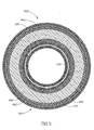
- duct 100 which may be used for gas transport or for enclosing utility lines, is cylindrical, having an axis 150, and is of multi-layer construction, as shown in detail in Fig. 2 .
- cylindrical duct 100 applies equally to non-cylindrical ducts, such as non-insulated square duct 1100 ( Figs. 13A-13B ) and insulated square duct 1400 ( Figs. 14A-14B ), as well as variations thereof, all as described hereinbelow.
- the term "helical,” and variations thereof, derives from the description of the manufacture of the ducts of the invention, and relates to the act of winding various elements in a spiral or helix.
- the helical windings clearly remain helical.
- the windings while not being strictly helical, retain a general square-helical arrangement, and may be referred to as such, although mainly they are referred to merely as “windings" or "wound.”
- Duct 100 has inner and outer sleeves, referenced 220 and 230, respectively, which are coaxial and are of a laminate construction, each preferably being formed of a wound helical wrapping of a two-layer laminated tape formed of two layers of ribbon, 222, 224, and 232, 234, respectively, bonded together with an adhesive layer 240, 280.
- Inner sleeve 220 has an internal layer of aluminum ribbon 222 and an external layer of polyester ribbon 224 bonded together with adhesive layer 240 to form a two-layer laminated tape which is helically wound around a mandrel (710, see Fig. 7 , discussed hereinbelow) to form inner sleeve 220.
- Coaxially wound around inner sleeve 220 is a wound helical wire 250, preferably of bronze-coated steel, disposed and encapsulated between inner sleeve 220 and outer sleeve 230 with a layer of adhesive 260.
- Outer sleeve 230 is fabricated in a manner similar to inner sleeve 220, but wherein, the helically wound two-layer laminated tape has an internal layer of polyester ribbon 234 and an external layer of aluminum ribbon 232, bonded together with adhesive layer 280.
- the wound bronze-coated steel wire 250 imparts corresponding corrugations 160 to duct 100, as can be seen in Fig. 1 .
- Polyester ribbon layers 224 and 234 are both heat resistant and fire retardant and further are made thick enough to contribute to the rigidity and structural integrity of duct 100 together with aluminum ribbon layers 222 and 232, which, being metallic, are fireproof as well.
- the adhesive employed in adhesive layers 240, 260, and 280 is also heat resistant and fire retardant. It should be noted that polyester ribbon layers 224 and 234 are also puncture resistant, which is a further advantage of the duct 100 of the present invention.
- Duct 100 is manufactured fully extended by a continuous process, further described hereinbelow, and is then cut to a desired length.
- the corrugations 160 imparted thereto by wound helical wire 250 allow duct 100 to be axially compressed into a compact configuration convenient for storage or shipping.
- duct 100 is compressed, as shown in Fig. 3 , aluminum layers 222 and 232 and polyester layers 224 and 234 naturally fold between the ridges (referenced 160 in Fig. 1 ) created by wound helical wire 250.
- a 2.4 meter length of 10 centimeter diameter duct fabricated in accordance with the present invention can be compressed to a length of approximately 15 centimeters, which is comparable to the compression of simple prior art ducts described hereinabove that do not have the advantages and improvements of the present invention.
- duct 100 maintains its rigidity and structural integrity and functions like a totally rigid duct even after having been compressed to its compact configuration and re-extended to its original length.
- Fig. 10 there is shown, schematically, the vertical sag c of the unsupported center 210 of a horizontal segment of duct 200 spanning between two supports 215 a distance L apart.
- a 1.5 meter horizontal span of 10 centimeter diameter duct with no support in its center will substantially maintain its rigid shape and sag in the unsupported center by no more than 1 centimeter, while a similar 2 meter horizontal span of 10 centimeter diameter duct will sag in the unsupported center by no more than 5 centimeters.
- a 1.5 meter horizontal span of 10 centimeter diameter duct that has no support in its center will maintain its rigid shape with negligible sag, while a 2 meter horizontal span of 10 centimeter diameter duct will sag in the unsupported center by no more than 1 centimeter.
- Fig. 11 there is shown, schematically, the vertical displacement y from the horizontal of one unsupported end 290 of a horizontal segment of duct 200 of length L, as a result of bending due to gravity, when the other end 295 has support 215.
- a vertically deployed segment of the duct of the present invention will maintain its rigidity, and not sag or collapse, even when returned to its extended configuration after having been compressed.
- these features represent a major improvement over the prior art, including solid aluminum corrugated tubes such as those employed in the invention of the Whitney patent ( U.S. Patent Number 5,281,187 ) discussed hereinabove.
- Another advantage of the unique multilayered construction of the present invention is that when it is fully extended after compression, the inward-facing surface of the aluminum layer 222 of the inner sleeve 220 is substantially smooth and featureless except for the helical corrugations imparted by wire winding 250. This reduces frictional resistance to air flow within the duct, and, for clothes dryer exhaust transition ducts, significantly impedes the accumulation of lint inside the duct, thereby greatly reducing the fire hazard cited hereinabove with respect to the prior art.
- duct 100 may have the following exemplary dimensions.
- the two-layer laminated tape of inner sleeve 220 has an inner aluminum ribbon layer 222 that is 7 microns thick and a polyester ribbon layer 224 that is 12 microns thick, so that, with the adhesive 240, inner sleeve 220 has a thickness of 21 microns.
- the wire helix 250 is a 0.9 mm diameter bronze-coated steel wire.
- the two-layer laminated tape of outer sleeve 230 has an outer aluminum ribbon layer 232 that is 25 microns thick and a polyester ribbon layer 234 that is 12 microns thick, so that, with the adhesive 280, outer sleeve 230 has a thickness of 39 microns.
- the use of the thinner (7 microns) aluminum ribbon layer 222 in inner sleeve 220 contributes to the above-mentioned smoothness of the inner surface of duct 100. It should be noted that the above-mentioned dimensions are typical and are exemplary of a preferred embodiment of the present invention, and that the present invention is not limited thereto.
- polyester layer 224 of inner sleeve 220 or polyester layer 234 of outer sleeve 230 may be omitted without loss of the improvements in rigidity of the present invention, albeit at a cost of additional thickness of aluminum, resulting in additional weight and expense.
- either of these alternative configurations should be considered as being included in the present invention, as well as alternative dimensions of the layers that can still provide the desired performance of duct 100.
- metallic layers or plastic layers fabricated of materials having properties comparable to those of the aluminum and polyester layers described hereinabove should also be considered as being included in the present invention.
- FIG. 4 there is shown a schematic oblique view of a segment of a duct, referred to generally as 400.
- a schematic axial cross-sectional view of duct 400 is shown in Fig. 5 .
- duct 400 is similar to that shown in Fig. 1 , but also includes an insulating layer 470 disposed parallel to and about outer sleeve 430 constructed and operative in accordance with a further preferred embodiment of the present invention.
- insulating layer 470 has an enclosing jacket serving as a vapor barrier, referred to generally as 490, disposed thereabout.
- Insulating layer 470 is typically fabricated of fiberglass, which provides the desired insulation and is fire resistant.
- Enclosing jacket 490 is formed of an inner helical winding of polyester ribbon 484, bonded with a layer of heat and fire retardant adhesive 485 and an outer helical winding of a two-layer laminated tape having an inner layer of polyester ribbon 494 and an outer layer of aluminum ribbon 492 bonded together by a heat resistant and fire retardant adhesive 495.
- insulating layer 470 and enclosing jacket 490 of duct 400 have the following dimensions.
- insulating layer 470 typically may be either 25 or 50 millimeters in thickness.
- the wrapping of polyester ribbon 484 is 12 microns thick.
- the two-layer laminated tape of the outer helical winding has an inner polyester ribbon layer 494 that is 12 microns thick and an outer aluminum ribbon layer 492 that is 7 microns thick, so that, with the adhesive 495, outer helical winding has a thickness of 21 microns. It should be noted that the above-mentioned dimensions are typical and are exemplary of a preferred embodiment of the present invention, and that the present invention is not limited thereto.
- Enclosing jacket 490 is manufactured by a continuous process, similar to that of duct 100, and is then cut to a desired length.
- Duct 400 is assembled from an insulating layer 470 cut to the desired length and an enclosing jacket 490 cut to the desired length, which are drawn onto a segment of uninsulated duct, similar to duct 100, cut to the desired length.
- a schematic view of a duct 600 constructed and operative in accordance with an embodiment of the present invention, installed as an exhaust transition duct of a clothes dryer 650.
- Duct 600 is connected to dryer exhaust port 640 and has a vertical segment 660 and two right angle bends 670 connecting it to an outside exhaust port 680, thereby allowing it to vent the exhaust gases of clothes dryer 650.
- the features of the present invention discussed hereinabove, notably the rigidity and structural integrity and the reduced tendency to accumulate lint are particularly advantageous in applications such as this.
- the size of the duct 700 being fabricated is determined by mandrel 710 which is rotated about its longitudinal axis 715.
- Inner two-layer laminate tape 720 is helically wound with a predetermined overlap 828 ( Fig. 8 ) around mandrel 710 as it turns to produce the two-layer inner sleeve of duct 700 as a first step in forming duct 700.
- Bronzed-coated steel wire 730 is helically wound around the two-layer inner sleeve of duct 700 as mandrel 710 turns with the two-layer inner sleeve formed thereupon.
- Outer two-layer laminate tape 740 is helically wound with a predetermined overlap 848 ( Fig. 8 ) around the two-layer inner sleeve of duct 700 with bronzed-coated steel wire 730 wound thereabout as mandrel 710 turns with the two-layer inner sleeve and the wire wound thereupon to produce the two-layer outer sleeve of duct 700.
- FIG. 8 there is shown an enlarged detailed schematic cross-sectional view of a portion of the wall of a duct, referred to generally as 800, constructed in accordance with the present invention, being fabricated according to the method of the present invention.
- Inner two-layer laminate tape referred to generally as 820
- outer two-layer laminate tape referred to generally as 840
- inner two-layer laminate tape 820 and outer two-layer laminate tape 840 are both prepared prior to their being helically wound around mandrel 710 ( Fig. 7 ) to fabricate duct 800, and that inner two-layer laminate tape 820 is wrapped around the mandrel with the aluminum ribbon 822 side inward toward the mandrel and outer two-layer laminate tape 840 is wrapped around the mandrel with the polyester ribbon 844 side inward toward the mandrel.
- inner two-layer laminate tape 820 and outer two-layer laminate tape 840 are each respectively helically wound with a predetermined partial overlap, 828 and 848 respectively, so that successive wrappings produce continuous inner and outer two-layer sleeves.
- wires of wire winding 830 are aligned approximately centered above the overlap 828 in inner two-layer laminate tape 820, and the overlap 848 in outer two-layer laminate tape 840 is aligned approximately centered above the spaces between the wires of wire winding 830, which has been found to enhance the strength and rigidity of duct 800.
- the outer, polyester ribbon 824 side of inner two-layer laminate tape 820 and the inner, polyester ribbon 844 side of outer two-layer laminate tape 840 are coated with a fire-retardant adhesive, such as with a rolling adhesive applicator, thereby allowing them to be bonded together with an adhesive layer 836 which also encapsulates bronzed-coated steel wire winding 830 therebetween, when all are wound around mandrel 710 ( Fig. 7 ) so as to fabricate duct 800.
- a fire-retardant adhesive such as with a rolling adhesive applicator
- both inner two-layer laminate tape 720 and outer two-layer laminate tape 740, as well as bronzed-coated steel wire 730, are all continuously and simultaneously wrapped and wound, respectively, around mandrel 710 as it rotates.
- the wrappings and the winding, while occurring simultaneously, are performed with predetermined phase differences, with respect to the rotation of mandrel 710, between them.
- duct 700 is fabricated in one continuous operation.
- the phase difference between the wrapping of inner two-layer laminate tape 720 and the winding of bronzed-coated steel wire 730 is 360 degrees or one complete rotation of mandrel 710
- the phase difference between the winding of bronzed-coated steel wire 730 and the wrapping of outer two-layer laminate tape 740 is 120 degrees or one third of a complete rotation of mandrel 710 about axis 715.
- enclosing jacket 490 is fabricated by a process analogous to that used to fabricate duct 700 described hereinabove.
- Fig. 9 there is shown a schematic axial view of an enclosing jacket, referred to generally as 900, in accordance with the present invention being fabricated according to the method of the present invention.
- a two-layer laminate tape 940 with an inner polyester ribbon layer and an outer aluminum ribbon layer bonded with a fire-retardant adhesive is formed.
- a continuous inner plastic sleeve is produced by helically winding a polyester ribbon 920 around a rotating mandrel 910 of the desired diameter, and a continuous outer two-layer sleeve is produced by helically winding the two-layer laminate tape 940 around the inner plastic sleeve as the mandrel rotates, with a fire-retardant adhesive layer applied therebetween.
- enclosing jacket 900 is produced in one continuous operation, with continuous inner plastic sleeve and outer two-layer sleeve both wrapped around mandrel 910 continuously and simultaneously, with only a specific phase difference, with respect to the rotation of mandrel 910, between them.
- the phase difference between the wrapping of the inner plastic sleeve and that of the outer two-layer sleeve is 360 degrees or one complete rotation of mandrel 910 about axis 915.
- an additional tape of open-mesh laid fiberglass scrim may be wrapped between polyester ribbon 920 and two-layer laminate tape 940 in enclosing jacket 900 (not pictured).
- a piece of continuously produced uninsulated duct 700 ( Fig. 7 ) is cut to the desired length, and a piece of continuously produced enclosing jacket 490 ( Fig. 5 ) is cut to the desired length.
- the desired length piece of enclosing jacket 490 together with an insulating fiberglass sheath 470 of the desired length and suitable inner and outer diameters, are drawn over the desired length piece of uninsulated duct 700 to produce the insulated duct 400 shown in Figs. 4 and 5 .
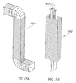
- ducts which are generally similar to those shown and described above in conjunction with Figs. 1-11 , and which have similar characteristics of strength, durability, puncture resistance and fire resistance, and thus are not specifically described again herein, save with reference to the differences between the ducts previously illustrated and those described hereinbelow. Accordingly, and for the sake of ease of reference, the ducts illustrated in Figs. 13A-15B , as well as portions thereof, are generally denoted by reference numerals which are the same as those used to indicate their respective counterpart ducts and portions thereof in Figs. 1-11 , but with the addition of the prefix "1.”
- the non-insulated duct illustrated in Figs. 13A-13B is referenced 1100
- the insulated duct illustrated in Figs. 14A-14B is referenced 1400.
- duct 1100 is a non-insulated polygonal duct, generally similar to that shown and described hereinabove in conjunction with Figs. 1-2 .
- it may be a square section duct used for gas transport, such as for ventilation, cooling, and heating systems, or for an exhaust system, as illustrated in Fig. 15A at 1600.
- duct 1400 is an insulated polygonal duct, generally similar to that shown and described hereinabove in conjunction with Figs. 4-5 .
- duct 1600' may be a rectangular section duct 1600', used for utility lines 1602, such as electricity communications, gas, or water.
- a portion of a compound duct 1148 which has both a cylindrical portion, referenced 100', substantially as shown and described above in conjunction with Figs. 1-3 ; and a square or rectangular portion, referenced 1100', substantially as shown and described above in conjunction with Figs. 13A-13B .
- the two differently shaped portions are connected via a transition portion 1150.
- compound duct 1148 is primarily cylindrical, and has a rectangular end portion so as to facilitate connection of the duct to the outlet ports of different types of gas emitting machines, wherein the outlet ports are square or rectangular.
- Use of the illustrated duct clearly avoids the necessity of unorthodox and sometimes unsafe connections, in order to connect a square or rectangular machine outlet to a cylindrical duct.
- the compound duct 1148 may be formed as described below in conjunction with Figs. 17A-17C , or by any other suitable method.
- the polygonal ducts of the present embodiment may be manufactured in substantially the same manner as shown and described hereinabove in conjunction with Figs. 7, 8 , and 12 , as may be observed from the first three steps of the flow chart of Fig. 16 , which are identical to those described hereinabove in conjunction with Fig. 12 .
- the cylindrical duct which results from the hitherto described method of manufacture is converted, either wholly or partially, into a polygonal duct, preferably square or rectangular, as shown at 1100' in Fig. 16 .
- conversion of a length of cylindrical duct 100 may be achieved by mounting a length thereof onto an expanding metal profile 2000, having an external shape adapted to expand to the shape and size desired.
- the profile is operated as known in the art, so as to expand against the interior surface of the round duct, thereby to deform it into a predetermined shape.
- it may also be desired to complement the outward deformation forces applied from the interior of the duct by the expanding metal profile 2000, by external deformation forces, such as may be provided by trolley 2002.
- Trolley 2002 comprises a chassis 2004, onto which are mounted a plurality of cylindrical wheels 2006 which, as seen in Fig.
- 17C define, together with wheels 2006, internal right-angled profiles 2008.
- the duct is stretched both from the interior by profile 2000, and is also squeezed between the profile 2000 and the inward-facing right-angled profiles of trolley 2002, thereby to impart to the duct a desired polygonal shape.
- this shape is rectangular, but this is by way of example only, as it could be any desired shape, whether rectangular, or any other type of polygon.
Landscapes
- Engineering & Computer Science (AREA)
- General Engineering & Computer Science (AREA)
- Mechanical Engineering (AREA)
- Chemical & Material Sciences (AREA)
- Combustion & Propulsion (AREA)
- Manufacturing & Machinery (AREA)
- Textile Engineering (AREA)
- Duct Arrangements (AREA)
- Rigid Pipes And Flexible Pipes (AREA)
Claims (17)
- Halbsteifer elastischer Kanal (100), der enthält:ein Paar koaxialer Muffen (220, 230), enthaltend eine Innenmuffe (220) und eine Außenmuffe (230), die parallel zur Innenmuffe (220) und um diese angeordnet ist; undein biegsames gewickeltes Drahtelement (250), das zwischen der Innenmuffe (220) und der Außenmuffe (230) angeordnet ist;wobei die Innenmuffe (220) eine innere erste Schicht aus Aluminiumband (222) vorab definierter Dicke und eine äußere zweite Schicht aus Polyesterband (224) vorab definierter Dicke aufweist, die ein erstes zweischichtiges durchgängiges laminiertes Band bilden,wobei die Außenmuffe (230) eine innere erste Schicht aus Polyesterband (234) vorab definierter Dicke und eine äußere zweite Schicht aus Aluminiumband (232) vorab definierter Dicke aufweist, die ein zweites zweischichtiges durchgängiges laminiertes Band bilden,wobei das gewickelte Drahtelement (250) der Innenmuffe (220) und der Außenmuffe (230) Wellen verleiht, so dass der Kanal (100) zwischen einer eingezogenen Konfiguration, die sich zur Lagerung und zum Transport eignet, und einer ausgezogenen Konfiguration, die sich zur Installation in einer Gastransportanordnung eignet, axial erweiterbar ist,dadurch gekennzeichnet, dass die Innenmuffe (220) aus einer gewickelten Umpackung aus dem ersten zweischichtigen durchgängigen laminierten Band mit einer vorab definierten Überlappung (828) um einen Dorn (710) gebildet ist, wobei das erste Aluminiumband (222) dem Dorn (710) einwärts zugewandt ist und das erste Polyesterband (224) in Bezug auf den Dorn (710) nach außen gerichtet ist, unddie Außenmuffe (230) aus einer gewickelten Umpackung des zweiten zweischichtigen durchgängigen laminierten Bandes mit einer vorab definierten Überlappung (848) um die zweischichtige Innenmuffe (220) und dem gewickelten Drahtelement (250) gebildet ist, wobei das zweite Polyesterband (234) dem Dorn (710) einwärts zugewandt ist und das zweite Aluminiumband (232) in Bezug auf den Dorn (710) nach außen gerichtet ist,wobei alle Schichten (222, 224, 232, 234) sowohl der Innenmuffe (220) als auch der Außenmuffe (230) eine Dicke und eine Überlappung (828, 848) aufweisen, die vorab definiert sind, um den Kanal (100) gemeinsam im Wesentlichen steif zu machen, wenn sich dieser in der ausgezogenen Konfiguration befindet, und um gemeinsam zu ermöglichen, dass der Kanal (100) seine wesentliche Steifheit beim Ausziehen aus der eingezogenen Konfiguration behält.
- Kanal nach Anspruch 1, dadurch gekennzeichnet, dass die Polyesterschicht (224, 234) von jedem der Innenmuffe (220) und der Außenmuffe (230) an die Aluminiumschicht (222, 232) gebunden ist, wodurch das innere zweischichtige Laminat (220) bzw. das äußere zweischichtige Laminat (230) gebildet werden.
- Kanal nach Anspruch 1, dadurch gekennzeichnet, dass der Kanal, wenn eine vorab definierte Länge L des Kanals (100) mit einem Durchmesser d in der ausgezogenen Konfiguration und horizontal angeordnet und an beiden Enden davon getragen wird, betreibbar ist, um sich unter Einwirkung der Gravitationskraft zu biegen, so dass der Mittelteil davon um nicht mehr als c niedriger als die Ebene der getragenen Enden ist, so dass (c/L)*100 ≤ q, wobei q ein vorab definierter Prozentsatz von L ist.
- Kanal nach Anspruch 2, dadurch gekennzeichnet, dass zumindest eines des Folgendes umfaßt ist:a) wobei sowohl das innere zweischichtige Laminat (220) als auch das äußere zweischichtige Laminat (230) aus feuerfesten Materialien hergestellt sind, und wobei die Polyesterschichten (224, 234) sowohl des inneren zweischichtigen Laminats (220) als auch des äußeren zweischichtigen Laminats (230) aus durchstoßfesten Materialien hergestellt sind;b) wobei die Polyesterschicht (224, 234) sowohl des inneren zweischichtigen Laminats (220) als auch des äußeren zweischichtigen Laminats (230) mithilfe eines feuerfesten Klebstoffs an die Aluminiumschicht (222, 232) davon gebunden ist, und wobei das innere zweischichtige Laminat (220) mithilfe eines feuerbeständigen Klebstoffs an das äußere zweischichtige Laminat (230) gebunden ist; undc) wobei die ersten Schichten (222, 232) des inneren zweischichtigen Laminats (220) und des äußeren zweischichtigen Laminats (230) aus Aluminiumband vorab definierter Dicken hergestellt sind, und wobei die zweiten Kunststoffschichten (224, 234) des inneren zweischichtigen Laminats (220) und des äußeren zweischichtigen Laminats (230) aus Polyesterband vorab definierter Dicken hergestellt sind, und wobei das Aluminiumband des inneren zweischichtigen Laminats (220) an das Polyesterband gebunden ist, um ein inneres zweischichtiges laminiertes Band vorab definierter Dicke zu bilden, und wobei das Aluminiumband des äußeren zweischichtigen Laminats (230) an das Polyesterband davon gebunden ist, um ein äußeres zweischichtiges laminiertes Band vorab definierter Dicke zu bilden, und wobei das innere zweischichtige Laminat (220) eine innere gewickelte Umpackung mit einer vorab definierter Überlappung des inneren zweischichtigen laminierten Bandes ist, und wobei das äußere zweischichtige Laminat (230) eine äußere gewickelte Umpackung mit einer vorab definierten Überlappung des äußeren zweischichtigen laminierten Bandes ist.
- Kanal nach Anspruch 4, dadurch gekennzeichnet, dass das biegsame gewickelte Element (250) mit der inneren gewickelten Umpackung ausgerichtet ist, um über der Überlappung (828) der inneren gewickelten Umpackung des inneren zweischichtigen laminierten Bandes ungefähr zentriert zu sein, und die äußere gewickelte Umpackung des äußeren zweischichtigen laminierten Bandes mit dem biegsamen gewickelten Element (250) ausgerichtet ist, so dass die Überlappung (848) der äußeren gewickelten Umpackung des äußeren zweischichtigen laminierten Bandes über den Räumen zwischen den Wicklungen des biegsamen gewickelten Elements (250) ungefähr zentriert ist.
- Kanal nach Anspruch 1, dadurch gekennzeichnet, dass er ferner eine Isolierummantelung (470), die parallel zu der Außenmuffe (430) und um diese angeordnet ist, und einen umschließenden Mantel (490) enthält, der parallel zur Isolierummantelung (470) und um diese angeordnet ist.
- Kanal nach Anspruch 6, dadurch gekennzeichnet, dass der umschließende Mantel (490) ein mehrschichtiger Mantel ist, der eine rohrförmige innere Kunststoffumpackung (484) und eine zweischichtige äußerere laminierte Umpackung (492, 494) enthält, parallel dazu und um diesen angeordnet und an diesen gebunden, und wobei die zweischichtige laminierte äußere Umpackung (492, 494) eine innere Kunststoffschicht (494) und eine äußere Schicht (492) mit metallischen Eigenschaften aufweist, die miteinander verbunden sind.
- Kanal nach Anspruch 7, dadurch gekennzeichnet, dass die innere Kunststoffumpackung (484) aus Polyesterband vorab definierter Dicke hergestellt ist, und wobei die innere Kunststoffschicht (494) der zweischichtigen laminierten äußeren Umpackung (492, 494) aus Polyesterband vorab definierter Dicke hergestellt ist, und wobei die äußere Schicht (492) mit metallischen Eigenschaften der zweischichtigen laminierten äußeren Umpackung (492, 494) aus Aluminiumband vorab definierter Dicke hergestellt ist.
- Kanal nach Anspruch 8, dadurch gekennzeichnet, dass die rohrförmige innere Kunststoffumpackung (484) und die zweischichtige laminierte äußere Umpackung (492, 494) mithilfe eines feuerfesten Klebstoffs miteinander verbunden sind, und wobei das Polyesterband und das Aluminiumband der zweischichtigen laminierten äußeren Umpackung (492, 494) mithilfe eines feuerfesten Klebstoffs miteinander verbunden sind.
- Kanal nach Anspruch 1, dadurch gekennzeichnet, dass der Kanal eine Querschnittskonfiguration aufweist, ausgewählt aus der Gruppe bestehend aus:kreisförmig;rechteckig;und polygonal.
- Verfahren zum Herstellen eines halbsteifen elastischen Kanals (100), umfassend die folgenden Schritte:a) Bereitstellen eines Dorns (710) mit einem vorab ausgewählten Durchmesser zur Herstellung eines Kanals (100) um diesen herum;b) Kombinierten eines ersten durchgängigen Aluminiumbandes (222) vorab definierter Dicke mit einem ersten durchgängigen Polyesterband (224) vorab definierter Dicke, um ein erstes durchgängiges zweischichtiges laminiertes Band zu bilden;c) Kombinieren eines zweiten durchgängigen Aluminiumbandes (232) vorab definierter Dicke mit einem zweiten durchgängigen Polyesterband (234) vorab definierter Dicke, um ein zweites durchgängiges zweischichtiges laminiertes Band zu bilden;d) Wickeln des ersten zweischichtigen laminierten durchgängigen Bands mit einer vorab definierten Überlappung (828) um den Dorn (710), wobei das erste Aluminiumband (222) dem Dorn (710) einwärts zugewandt ist, und wobei das erste Polyesterband (224) in Bezug auf den Dorn (710) nach außen gerichtet ist, um eine zweischichtige Innenmuffe (220) zu bilden;e) Wickeln eines Drahts (250) um die zweischichtige Innenmuffe (220); undf) Wickeln des zweiten zweischichtigen laminierten durchgängigen Bandes mit einer vorab definierten Überlappung (848) um die zweischichtige Innenmuffe (220) und die Drahtwicklung (250), wobei das zweite Polyesterband (234) dem Dorn einwärts zugewandt ist, und wobei das zweite Aluminiumband (232) in Bezug auf den Dorn (710) nach außen gerichtet ist, um eine zweischichtige Außenmuffe (230) zu bilden, die parallel zur zweischichtigen Innenmuffe (220) und um diese angeordnet ist, um somit einen Kanal (100) zu bilden.
- Verfahren nach Anspruch 11, umfassend zumindest eines des Folgenden:A. Schritt b) des Kombinierens eines ersten Aluminiumbandes (222) enthält den Unterschritt des Auftragens eines feuerfesten Klebstoffs zwischen dem ersten Aluminiumband (222) und dem ersten Polyesterband (224), um diese miteinander zu verbinden; und wobei Schritt c) des Kombinierens eines zweiten Aluminiumbands (232) den Unterschritt des Auftragens eines feuerfesten Klebstoffs zwischen dem zweiten Aluminiumband (232) und dem zweiten Polyesterband (234) enthält, um diese miteinander zu verbinden;B. die zweischichtige Außenmuffe (230) in Schritt f) des Wickelns des zweiten zweischichtigen laminierten durchgängigen Bandes mithilfe eines feuerfesten Klebstoffs mit der zweischichtigen Innenmuffe (220) verbunden wird, wobei der Draht (250) um die zweischichtige Außenmuffe (230) und die zweischichtige Innenmuffe (220) gewickelt wird;C. nach Schritt f) des Wickelns des zweiten zweischichtigen laminierten durchgängigen Bandes die folgenden Schritte:g) Ummanteln der zweischichtigen Außenmuffe (430) mit einer Fiberglasisolierungsummantelung (470), die parallel dazu und um diese angeordnet ist; undh) Umschließen der Isolierungsummantelung (470) mit einem umschließenden Mantel (490);D. Schritt e) des Wickelns eines Drahts (250) den Unterschritt des Ausrichtens des Drahts (250) mit der Überlappung (828) des ersten zweischichtigen laminierten durchgängigen Bandes enthält, so dass der Draht (250) über der Überlappung (828) des ersten zweischichtigen laminierten durchgängigen Bandes ungefähr zentriert ist, und wobei Schritt f) des Wickelns des zweiten zweischichtigen laminierten durchgängigen Bandes den Unterschritt des Ausrichtens des zweiten zweischichtigen laminierten durchgängigen Bandes enthält, so dass die Überlappung (848) davon über den Räumen zwischen den Drahtwicklungen (250) ungefähr zentriert ist;E. Schritt d) des Wickelns des ersten zweischichtigen laminierten durchgängigen Bandes, Schritt e) des Wickelns des Drahts (250) und Schritt f) des Wickelns des zweiten zweischichtigen laminierten durchgängige Bandes durch Drehen des Dorns (710) durchgeführt werden, wenn das erste zweischichtige laminierte durchgängige Band, der Draht (250) und das zweite zweischichtige laminierte durchgängige Band jeweils vom Dorn (710) aufgenommen werden, kontinuierlich und mit vorab definierten Phasendifferenzen dazwischen in Bezug auf die Drehung des Dorns (710).
- Verfahren nach Anspruch 12 E, wobei Schritt d) des Wickelns des ersten zweischichtigen laminierten durchgängigen Bandes und Schritt e) des Wickelns des Drahts kontinuierlich und mit einer ersten vorab ausgewählten Phasendifferenz dazwischen in Bezug auf die Drehung des Dorns (710) durchgeführt werden; und wobei Schritt e) des Wickelns des Drahts (250) und Schritt f) des Wickelns des zweiten zweischichtigen laminierten durchgängigen Bandes kontinuierlich und mit einer zweiten vorab ausgewählten Phasendifferenz dazwischen in Bezug auf die Drehung des Dorns (710) durchgeführt werden.
- Verfahren nach Anspruch 12 C, wobei Schritt h) des Umschließens die folgenden Unterschritte umfasst:i) Bereitstellen eines Dorns mit einem vorab ausgewählten Durchmesser zur Herstellung des umschließenden Mantels (490) um diesen herum;ii) Kombinieren eines durchgängigen Polyesterbandes (494) vorab definierter Dicke mit einem durchgängigen Aluminiumband (492) vorab definierter Dicke, um ein zweischichtiges laminiertes durchgängiges Band zu bilden;iii) Wickeln eines durchgängigen Polyesterbandes (484) vorab definierter Dicke um den Dorn, um eine Kunststoff-Innenmuffe zu bilden;iv) Wickeln des durchgängigen zweischichtigen laminierten Bandes um die Kunststoff-Innenmuffe (484), wobei das Polyesterband (494) dem Dorn einwärts zugewandt ist und das Aluminiumband (492) in Bezug auf den Dorn nach außen gerichtet ist, um eine zweischichtige Außenmuffe zu bilden, die parallel zur Kunststoff-Innenmuffe und um diese angeordnet ist.
- Verfahren nach Anspruch 14, umfassend zumindest eines des Folgenden:A. Unterschritt ii) des Kombinierens enthält den Teilunterschritt des Auftragens eines feuerfesten Klebstoffs (485) zwischen dem Polyesterband (484) und dem Aluminiumband (492) des durchgängigen zweischichtigen laminierten Bandes, um diese miteinander zu verbinden;B. Unterschritt iii) des Wickelns eines Polyesterbandes (484) enthält den Teilunterschritt des Beschichtens der Außenfläche der Kunststoff-Innenmuffe mit einem feuerfesten Klebstoff (485), um diese mit dem zweischichtigen laminierten Band zu verbinden.
- Verfahren nach Anspruch 14, wobei der Unterschritt iii) des Wickelns eines Polyesterbandes (484) und der Unterschritt iv) des Wickelns des zweischichtigen laminierten Bandes durch Drehen des Dorns durchgeführt werden, wenn das Polyesterband (484) und das zweischichtige laminierte Band jeweils vom Dorn aufgenommen werden, kontinuierlich und mit einer vorab definierten Phasendifferenz dazwischen in Bezug auf die Drehung des Dorns.
- Verfahren nach Anspruch 11, ferner umfassend den zusätzlichen Schritt des Anwendens einer viereckigen oder rechteckigen Querschnittskonfiguration auf zumindest einen Teil des Kanals (100).
Applications Claiming Priority (3)
| Application Number | Priority Date | Filing Date | Title |
|---|---|---|---|
| US11/389,623 US20070220732A1 (en) | 2006-03-24 | 2006-03-24 | Flexible semi-rigid clothes dryer duct |
| IL181023A IL181023A0 (en) | 2007-01-28 | 2007-01-28 | Semi-rigid flexible duct |
| PCT/IL2007/000362 WO2007110860A2 (en) | 2006-03-24 | 2007-03-20 | Semi-rigid flexible duct |
Publications (3)
| Publication Number | Publication Date |
|---|---|
| EP2002163A2 EP2002163A2 (de) | 2008-12-17 |
| EP2002163A4 EP2002163A4 (de) | 2011-05-18 |
| EP2002163B1 true EP2002163B1 (de) | 2012-05-30 |
Family
ID=38541528
Family Applications (1)
| Application Number | Title | Priority Date | Filing Date |
|---|---|---|---|
| EP07713380A Not-in-force EP2002163B1 (de) | 2006-03-24 | 2007-03-20 | Halbstarrer flexibler kanal |
Country Status (2)
| Country | Link |
|---|---|
| EP (1) | EP2002163B1 (de) |
| WO (1) | WO2007110860A2 (de) |
Cited By (1)
| Publication number | Priority date | Publication date | Assignee | Title |
|---|---|---|---|---|
| NL2035880B1 (nl) * | 2023-09-26 | 2025-04-01 | Quatrofolium Holding B V | Warmtepomp of WTW-unit luchtslang |
Families Citing this family (3)
| Publication number | Priority date | Publication date | Assignee | Title |
|---|---|---|---|---|
| FR3036171B1 (fr) * | 2015-05-11 | 2021-03-19 | Atlantic Climatisation & Ventilation | Gaine aeraulique d'une installation de ventilation |
| JP2021076266A (ja) * | 2019-11-06 | 2021-05-20 | フジモリ産業株式会社 | 空調ダクト |
| WO2024238438A1 (en) * | 2023-05-12 | 2024-11-21 | Flexible Technologies, Inc. | Class 1 flexible uninsulated duct with polymer core and integrated flame resistant barrier material, method of use, and method of making |
Family Cites Families (10)
| Publication number | Priority date | Publication date | Assignee | Title |
|---|---|---|---|---|
| FR2410202A1 (fr) * | 1977-11-25 | 1979-06-22 | Lebreton Gilbert | Gaine pour le transport d'un fluide, procede et machine pour sa fabrication |
| US5182147A (en) * | 1988-10-14 | 1993-01-26 | Dantec Ltd. | Composite hose |
| CA2051722A1 (en) * | 1990-12-12 | 1992-06-13 | William R. Gray | Flexible duct |
| WO1998026921A1 (en) * | 1996-12-17 | 1998-06-25 | Walter Kaczorowski | The method of manufacturing a pipe having bending capability and a pipe having bending capability |
| US6003561A (en) * | 1998-04-16 | 1999-12-21 | Southeastern Universities Research Assn., Inc. | Flexible cryogenic conduit |
| US6105621A (en) * | 1998-04-29 | 2000-08-22 | Primich; Theodore | Flexible oval duct for heating and cooling systems and method such ducts |
| FR2781862B1 (fr) * | 1998-08-03 | 2000-10-13 | Strulik Sa | Conduit d'aeration ou de chauffage souple et incombustible |
| US6527014B1 (en) * | 1999-11-30 | 2003-03-04 | Owens Corning Fiberglas Technology, Inc. | Flexible duct insulation having improved flame resistance |
| FR2827031B1 (fr) * | 2001-07-06 | 2004-02-13 | Strulik Sa | Conduit flexible |
| GR1004701B (el) * | 2004-02-04 | 2004-10-18 | Davlaras Apostolos | Ευκαμπτος αεραγωγος με εσωτερικη μονωση αφρωδους πολυαιθυλενιου |
-
2007
- 2007-03-20 WO PCT/IL2007/000362 patent/WO2007110860A2/en not_active Ceased
- 2007-03-20 EP EP07713380A patent/EP2002163B1/de not_active Not-in-force
Cited By (2)
| Publication number | Priority date | Publication date | Assignee | Title |
|---|---|---|---|---|
| NL2035880B1 (nl) * | 2023-09-26 | 2025-04-01 | Quatrofolium Holding B V | Warmtepomp of WTW-unit luchtslang |
| EP4530513A1 (de) * | 2023-09-26 | 2025-04-02 | Quatrofolium Holding B.V. | Luftanschlussschlauch für eine wärmepumpe oder wärmerückgewinnungsanlage |
Also Published As
| Publication number | Publication date |
|---|---|
| EP2002163A4 (de) | 2011-05-18 |
| EP2002163A2 (de) | 2008-12-17 |
| WO2007110860A3 (en) | 2009-04-09 |
| WO2007110860A2 (en) | 2007-10-04 |
Similar Documents
| Publication | Publication Date | Title |
|---|---|---|
| US8439085B2 (en) | Semi-rigid flexible duct | |
| US8469062B2 (en) | Durable semi-rigid flexible duct | |
| US20070235101A1 (en) | Semi-rigid flexible duct | |
| US20070235100A1 (en) | Double walled, self-insulating, lightweight duct | |
| EP2002163B1 (de) | Halbstarrer flexibler kanal | |
| US11181223B2 (en) | Insulated pipe | |
| CA3061658C (en) | Insulated flexible duct using compressible core spacer and method of use | |
| JP2002516975A (ja) | 伸展可能でかつ巻取り可能な部材 | |
| US12165791B2 (en) | Low-profile cable armor | |
| HU221031B1 (hu) | Eljárás cső szigetelésére | |
| US20070220732A1 (en) | Flexible semi-rigid clothes dryer duct | |
| CA2475171C (en) | Piping element and manufacturing method and apparatus | |
| KR20060113408A (ko) | 초전도체 케이블 | |
| EP2113375A1 (de) | Belüftungskanalsystem | |
| CN1179165C (zh) | 耐火隔热通道 | |
| JP4623401B2 (ja) | 超電導ケーブルの製造方法 | |
| US20070079884A1 (en) | Heat shrunk double wall, self-insulating, lightweight duct | |
| US7472724B2 (en) | Method and apparatus for creating, using, and dispensing tubes | |
| CN113757488B (zh) | 一种预浸料型管道保温装置及其施工方法、施工设备 | |
| KR102437713B1 (ko) | 전선관 일체형 케이블을 이용한 배관 배선 시공 방법 | |
| KR20210149347A (ko) | 전선관 일체형 가요성 금속피 케이블 | |
| HUP0003237A2 (en) | Pipe shell insulating pipe, arrangments for insulating pipes and method for manufacturing pipe shell | |
| JP3161118U (ja) | 空調用ダクト | |
| EP2994687A1 (de) | Thermisch isolierte rohrleitung für den transport von flüssigkeiten | |
| JP6914032B2 (ja) | 保温フレキシブルダクト |
Legal Events
| Date | Code | Title | Description |
|---|---|---|---|
| PUAI | Public reference made under article 153(3) epc to a published international application that has entered the european phase |
Free format text: ORIGINAL CODE: 0009012 |
|
| 17P | Request for examination filed |
Effective date: 20081023 |
|
| AK | Designated contracting states |
Kind code of ref document: A2 Designated state(s): AT BE BG CH CY CZ DE DK EE ES FI FR GB GR HU IE IS IT LI LT LU LV MC MT NL PL PT RO SE SI SK TR |
|
| AX | Request for extension of the european patent |
Extension state: AL BA HR MK RS |
|
| RIN1 | Information on inventor provided before grant (corrected) |
Inventor name: LIEBSON, GRAEME Inventor name: COHEN, ROBERT Inventor name: LIEBSON, STEVEN |
|
| R17D | Deferred search report published (corrected) |
Effective date: 20090409 |
|
| RIC1 | Information provided on ipc code assigned before grant |
Ipc: F16L 11/00 20060101AFI20090612BHEP |
|
| A4 | Supplementary search report drawn up and despatched |
Effective date: 20110414 |
|
| RIC1 | Information provided on ipc code assigned before grant |
Ipc: F16L 11/112 20060101AFI20110408BHEP Ipc: F24F 13/02 20060101ALI20110408BHEP Ipc: B29C 53/58 20060101ALI20110408BHEP Ipc: F16L 11/24 20060101ALI20110408BHEP Ipc: F16L 11/08 20060101ALI20110408BHEP Ipc: D06F 58/20 20060101ALI20110408BHEP |
|
| REG | Reference to a national code |
Ref country code: DE Ref legal event code: R079 Ref document number: 602007022971 Country of ref document: DE Free format text: PREVIOUS MAIN CLASS: F16L0011000000 Ipc: F16L0011112000 |
|
| GRAP | Despatch of communication of intention to grant a patent |
Free format text: ORIGINAL CODE: EPIDOSNIGR1 |
|
| RIC1 | Information provided on ipc code assigned before grant |
Ipc: F16L 11/24 20060101ALI20111128BHEP Ipc: F24F 13/02 20060101ALI20111128BHEP Ipc: D06F 58/20 20060101ALI20111128BHEP Ipc: B29C 53/58 20060101ALI20111128BHEP Ipc: F16L 11/08 20060101ALI20111128BHEP Ipc: F16L 11/112 20060101AFI20111128BHEP |
|
| DAX | Request for extension of the european patent (deleted) | ||
| GRAS | Grant fee paid |
Free format text: ORIGINAL CODE: EPIDOSNIGR3 |
|
| GRAA | (expected) grant |
Free format text: ORIGINAL CODE: 0009210 |
|
| AK | Designated contracting states |
Kind code of ref document: B1 Designated state(s): AT BE BG CH CY CZ DE DK EE ES FI FR GB GR HU IE IS IT LI LT LU LV MC MT NL PL PT RO SE SI SK TR |
|
| REG | Reference to a national code |
Ref country code: GB Ref legal event code: FG4D |
|
| REG | Reference to a national code |
Ref country code: CH Ref legal event code: EP |
|
| REG | Reference to a national code |
Ref country code: AT Ref legal event code: REF Ref document number: 560234 Country of ref document: AT Kind code of ref document: T Effective date: 20120615 |
|
| REG | Reference to a national code |
Ref country code: IE Ref legal event code: FG4D |
|
| REG | Reference to a national code |
Ref country code: DE Ref legal event code: R096 Ref document number: 602007022971 Country of ref document: DE Effective date: 20120726 |
|
| REG | Reference to a national code |
Ref country code: NL Ref legal event code: T3 |
|
| REG | Reference to a national code |
Ref country code: LT Ref legal event code: MG4D Effective date: 20120530 |
|
| PG25 | Lapsed in a contracting state [announced via postgrant information from national office to epo] |
Ref country code: FI Free format text: LAPSE BECAUSE OF FAILURE TO SUBMIT A TRANSLATION OF THE DESCRIPTION OR TO PAY THE FEE WITHIN THE PRESCRIBED TIME-LIMIT Effective date: 20120530 Ref country code: IS Free format text: LAPSE BECAUSE OF FAILURE TO SUBMIT A TRANSLATION OF THE DESCRIPTION OR TO PAY THE FEE WITHIN THE PRESCRIBED TIME-LIMIT Effective date: 20120930 Ref country code: SE Free format text: LAPSE BECAUSE OF FAILURE TO SUBMIT A TRANSLATION OF THE DESCRIPTION OR TO PAY THE FEE WITHIN THE PRESCRIBED TIME-LIMIT Effective date: 20120530 Ref country code: CY Free format text: LAPSE BECAUSE OF FAILURE TO SUBMIT A TRANSLATION OF THE DESCRIPTION OR TO PAY THE FEE WITHIN THE PRESCRIBED TIME-LIMIT Effective date: 20120530 Ref country code: LT Free format text: LAPSE BECAUSE OF FAILURE TO SUBMIT A TRANSLATION OF THE DESCRIPTION OR TO PAY THE FEE WITHIN THE PRESCRIBED TIME-LIMIT Effective date: 20120530 |
|
| REG | Reference to a national code |
Ref country code: AT Ref legal event code: MK05 Ref document number: 560234 Country of ref document: AT Kind code of ref document: T Effective date: 20120530 |
|
| PG25 | Lapsed in a contracting state [announced via postgrant information from national office to epo] |
Ref country code: SI Free format text: LAPSE BECAUSE OF FAILURE TO SUBMIT A TRANSLATION OF THE DESCRIPTION OR TO PAY THE FEE WITHIN THE PRESCRIBED TIME-LIMIT Effective date: 20120530 Ref country code: GR Free format text: LAPSE BECAUSE OF FAILURE TO SUBMIT A TRANSLATION OF THE DESCRIPTION OR TO PAY THE FEE WITHIN THE PRESCRIBED TIME-LIMIT Effective date: 20120831 Ref country code: LV Free format text: LAPSE BECAUSE OF FAILURE TO SUBMIT A TRANSLATION OF THE DESCRIPTION OR TO PAY THE FEE WITHIN THE PRESCRIBED TIME-LIMIT Effective date: 20120530 |
|
| PG25 | Lapsed in a contracting state [announced via postgrant information from national office to epo] |
Ref country code: BE Free format text: LAPSE BECAUSE OF FAILURE TO SUBMIT A TRANSLATION OF THE DESCRIPTION OR TO PAY THE FEE WITHIN THE PRESCRIBED TIME-LIMIT Effective date: 20120530 |
|
| PG25 | Lapsed in a contracting state [announced via postgrant information from national office to epo] |
Ref country code: SK Free format text: LAPSE BECAUSE OF FAILURE TO SUBMIT A TRANSLATION OF THE DESCRIPTION OR TO PAY THE FEE WITHIN THE PRESCRIBED TIME-LIMIT Effective date: 20120530 Ref country code: CZ Free format text: LAPSE BECAUSE OF FAILURE TO SUBMIT A TRANSLATION OF THE DESCRIPTION OR TO PAY THE FEE WITHIN THE PRESCRIBED TIME-LIMIT Effective date: 20120530 Ref country code: AT Free format text: LAPSE BECAUSE OF FAILURE TO SUBMIT A TRANSLATION OF THE DESCRIPTION OR TO PAY THE FEE WITHIN THE PRESCRIBED TIME-LIMIT Effective date: 20120530 Ref country code: DK Free format text: LAPSE BECAUSE OF FAILURE TO SUBMIT A TRANSLATION OF THE DESCRIPTION OR TO PAY THE FEE WITHIN THE PRESCRIBED TIME-LIMIT Effective date: 20120530 Ref country code: RO Free format text: LAPSE BECAUSE OF FAILURE TO SUBMIT A TRANSLATION OF THE DESCRIPTION OR TO PAY THE FEE WITHIN THE PRESCRIBED TIME-LIMIT Effective date: 20120530 Ref country code: EE Free format text: LAPSE BECAUSE OF FAILURE TO SUBMIT A TRANSLATION OF THE DESCRIPTION OR TO PAY THE FEE WITHIN THE PRESCRIBED TIME-LIMIT Effective date: 20120530 |
|
| PG25 | Lapsed in a contracting state [announced via postgrant information from national office to epo] |
Ref country code: PL Free format text: LAPSE BECAUSE OF FAILURE TO SUBMIT A TRANSLATION OF THE DESCRIPTION OR TO PAY THE FEE WITHIN THE PRESCRIBED TIME-LIMIT Effective date: 20120530 Ref country code: IT Free format text: LAPSE BECAUSE OF FAILURE TO SUBMIT A TRANSLATION OF THE DESCRIPTION OR TO PAY THE FEE WITHIN THE PRESCRIBED TIME-LIMIT Effective date: 20120530 Ref country code: PT Free format text: LAPSE BECAUSE OF FAILURE TO SUBMIT A TRANSLATION OF THE DESCRIPTION OR TO PAY THE FEE WITHIN THE PRESCRIBED TIME-LIMIT Effective date: 20121001 |
|
| PLBE | No opposition filed within time limit |
Free format text: ORIGINAL CODE: 0009261 |
|
| STAA | Information on the status of an ep patent application or granted ep patent |
Free format text: STATUS: NO OPPOSITION FILED WITHIN TIME LIMIT |
|
| PG25 | Lapsed in a contracting state [announced via postgrant information from national office to epo] |
Ref country code: ES Free format text: LAPSE BECAUSE OF FAILURE TO SUBMIT A TRANSLATION OF THE DESCRIPTION OR TO PAY THE FEE WITHIN THE PRESCRIBED TIME-LIMIT Effective date: 20120910 |
|
| 26N | No opposition filed |
Effective date: 20130301 |
|
| REG | Reference to a national code |
Ref country code: DE Ref legal event code: R097 Ref document number: 602007022971 Country of ref document: DE Effective date: 20130301 |
|
| PG25 | Lapsed in a contracting state [announced via postgrant information from national office to epo] |
Ref country code: BG Free format text: LAPSE BECAUSE OF FAILURE TO SUBMIT A TRANSLATION OF THE DESCRIPTION OR TO PAY THE FEE WITHIN THE PRESCRIBED TIME-LIMIT Effective date: 20120830 |
|
| PG25 | Lapsed in a contracting state [announced via postgrant information from national office to epo] |
Ref country code: MC Free format text: LAPSE BECAUSE OF NON-PAYMENT OF DUE FEES Effective date: 20130331 |
|
| REG | Reference to a national code |
Ref country code: IE Ref legal event code: MM4A |
|
| PG25 | Lapsed in a contracting state [announced via postgrant information from national office to epo] |
Ref country code: IE Free format text: LAPSE BECAUSE OF NON-PAYMENT OF DUE FEES Effective date: 20130320 |
|
| PG25 | Lapsed in a contracting state [announced via postgrant information from national office to epo] |
Ref country code: MT Free format text: LAPSE BECAUSE OF FAILURE TO SUBMIT A TRANSLATION OF THE DESCRIPTION OR TO PAY THE FEE WITHIN THE PRESCRIBED TIME-LIMIT Effective date: 20120530 |
|
| REG | Reference to a national code |
Ref country code: NL Ref legal event code: V1 Effective date: 20141001 |
|
| GBPC | Gb: european patent ceased through non-payment of renewal fee |
Effective date: 20140320 |
|
| PG25 | Lapsed in a contracting state [announced via postgrant information from national office to epo] |
Ref country code: GB Free format text: LAPSE BECAUSE OF NON-PAYMENT OF DUE FEES Effective date: 20140320 |
|
| PG25 | Lapsed in a contracting state [announced via postgrant information from national office to epo] |
Ref country code: NL Free format text: LAPSE BECAUSE OF NON-PAYMENT OF DUE FEES Effective date: 20141001 |
|
| REG | Reference to a national code |
Ref country code: NL Ref legal event code: RD1H Effective date: 20150319 |
|
| REG | Reference to a national code |
Ref country code: GB Ref legal event code: S28 Free format text: APPLICATION FILED |
|
| REG | Reference to a national code |
Ref country code: GB Ref legal event code: S28 Free format text: RESTORATION ALLOWED Effective date: 20150423 |
|
| PG25 | Lapsed in a contracting state [announced via postgrant information from national office to epo] |
Ref country code: TR Free format text: LAPSE BECAUSE OF FAILURE TO SUBMIT A TRANSLATION OF THE DESCRIPTION OR TO PAY THE FEE WITHIN THE PRESCRIBED TIME-LIMIT Effective date: 20120530 |
|
| REG | Reference to a national code |
Ref country code: NL Ref legal event code: RD2H Effective date: 20150714 |
|
| REG | Reference to a national code |
Ref country code: NL Ref legal event code: RD2H Effective date: 20150714 |
|
| PG25 | Lapsed in a contracting state [announced via postgrant information from national office to epo] |
Ref country code: LU Free format text: LAPSE BECAUSE OF NON-PAYMENT OF DUE FEES Effective date: 20130320 Ref country code: HU Free format text: LAPSE BECAUSE OF FAILURE TO SUBMIT A TRANSLATION OF THE DESCRIPTION OR TO PAY THE FEE WITHIN THE PRESCRIBED TIME-LIMIT; INVALID AB INITIO Effective date: 20070320 |
|
| REG | Reference to a national code |
Ref country code: FR Ref legal event code: PLFP Year of fee payment: 10 |
|
| REG | Reference to a national code |
Ref country code: FR Ref legal event code: PLFP Year of fee payment: 11 |
|
| PGFP | Annual fee paid to national office [announced via postgrant information from national office to epo] |
Ref country code: CH Payment date: 20170322 Year of fee payment: 11 Ref country code: NL Payment date: 20170321 Year of fee payment: 11 Ref country code: FR Payment date: 20170322 Year of fee payment: 11 Ref country code: DE Payment date: 20170322 Year of fee payment: 11 |
|
| PGFP | Annual fee paid to national office [announced via postgrant information from national office to epo] |
Ref country code: GB Payment date: 20170322 Year of fee payment: 11 |
|
| REG | Reference to a national code |
Ref country code: DE Ref legal event code: R119 Ref document number: 602007022971 Country of ref document: DE |
|
| REG | Reference to a national code |
Ref country code: CH Ref legal event code: PL |
|
| REG | Reference to a national code |
Ref country code: NL Ref legal event code: MM Effective date: 20180401 |
|
| GBPC | Gb: european patent ceased through non-payment of renewal fee |
Effective date: 20180320 |
|
| PG25 | Lapsed in a contracting state [announced via postgrant information from national office to epo] |
Ref country code: NL Free format text: LAPSE BECAUSE OF NON-PAYMENT OF DUE FEES Effective date: 20180401 |
|
| PG25 | Lapsed in a contracting state [announced via postgrant information from national office to epo] |
Ref country code: DE Free format text: LAPSE BECAUSE OF NON-PAYMENT OF DUE FEES Effective date: 20181002 |
|
| PG25 | Lapsed in a contracting state [announced via postgrant information from national office to epo] |
Ref country code: LI Free format text: LAPSE BECAUSE OF NON-PAYMENT OF DUE FEES Effective date: 20180331 Ref country code: CH Free format text: LAPSE BECAUSE OF NON-PAYMENT OF DUE FEES Effective date: 20180331 Ref country code: GB Free format text: LAPSE BECAUSE OF NON-PAYMENT OF DUE FEES Effective date: 20180320 |
|
| PG25 | Lapsed in a contracting state [announced via postgrant information from national office to epo] |
Ref country code: FR Free format text: LAPSE BECAUSE OF NON-PAYMENT OF DUE FEES Effective date: 20180331 |