EP2001260A2 - Sicheres Schaltsystem für Sprache und Daten mit einer modularen verteilten Architektur - Google Patents
Sicheres Schaltsystem für Sprache und Daten mit einer modularen verteilten Architektur Download PDFInfo
- Publication number
- EP2001260A2 EP2001260A2 EP08425390A EP08425390A EP2001260A2 EP 2001260 A2 EP2001260 A2 EP 2001260A2 EP 08425390 A EP08425390 A EP 08425390A EP 08425390 A EP08425390 A EP 08425390A EP 2001260 A2 EP2001260 A2 EP 2001260A2
- Authority
- EP
- European Patent Office
- Prior art keywords
- per
- data
- voice
- signalling
- devices
- Prior art date
- Legal status (The legal status is an assumption and is not a legal conclusion. Google has not performed a legal analysis and makes no representation as to the accuracy of the status listed.)
- Withdrawn
Links
Images

Classifications
-
- H—ELECTRICITY
- H04—ELECTRIC COMMUNICATION TECHNIQUE
- H04Q—SELECTING
- H04Q11/00—Selecting arrangements for multiplex systems
- H04Q11/04—Selecting arrangements for multiplex systems for time-division multiplexing
- H04Q11/0421—Circuit arrangements therefor
-
- H—ELECTRICITY
- H04—ELECTRIC COMMUNICATION TECHNIQUE
- H04Q—SELECTING
- H04Q2213/00—Indexing scheme relating to selecting arrangements in general and for multiplex systems
- H04Q2213/13003—Constructional details of switching devices
-
- H—ELECTRICITY
- H04—ELECTRIC COMMUNICATION TECHNIQUE
- H04Q—SELECTING
- H04Q2213/00—Indexing scheme relating to selecting arrangements in general and for multiplex systems
- H04Q2213/13106—Microprocessor, CPU
-
- H—ELECTRICITY
- H04—ELECTRIC COMMUNICATION TECHNIQUE
- H04Q—SELECTING
- H04Q2213/00—Indexing scheme relating to selecting arrangements in general and for multiplex systems
- H04Q2213/13107—Control equipment for a part of the connection, distributed control, co-processing
-
- H—ELECTRICITY
- H04—ELECTRIC COMMUNICATION TECHNIQUE
- H04Q—SELECTING
- H04Q2213/00—Indexing scheme relating to selecting arrangements in general and for multiplex systems
- H04Q2213/13174—Data transmission, file transfer
-
- H—ELECTRICITY
- H04—ELECTRIC COMMUNICATION TECHNIQUE
- H04Q—SELECTING
- H04Q2213/00—Indexing scheme relating to selecting arrangements in general and for multiplex systems
- H04Q2213/13178—Control signals
-
- H—ELECTRICITY
- H04—ELECTRIC COMMUNICATION TECHNIQUE
- H04Q—SELECTING
- H04Q2213/00—Indexing scheme relating to selecting arrangements in general and for multiplex systems
- H04Q2213/13216—Code signals, frame structure
-
- H—ELECTRICITY
- H04—ELECTRIC COMMUNICATION TECHNIQUE
- H04Q—SELECTING
- H04Q2213/00—Indexing scheme relating to selecting arrangements in general and for multiplex systems
- H04Q2213/13339—Ciphering, encryption, security
-
- H—ELECTRICITY
- H04—ELECTRIC COMMUNICATION TECHNIQUE
- H04Q—SELECTING
- H04Q2213/00—Indexing scheme relating to selecting arrangements in general and for multiplex systems
- H04Q2213/1336—Synchronisation
Definitions
- the invention consists of a Switching System for voice and data implemented by means of a modular, distributed architecture like the one described as a possible example, but not limited to it, by Fig. 1 , being such architecture implemented by means of a plurality of PSTN line interface devices (L) connected to a signalling interface and switching device (H) each by a digital bidirectional link (T), being a plurality of subscriber terminal line interface devices (S) connected by digital bidirectional link ( T ) to the above signalling interface and switching device (H) where one or more S devices may be connected in cascade to the same T link, being a plurality of subscriber terminal devices (P) connected to the above S devices via corresponding subscriber terminal lines and being, finally, a Call Server device (CS) connected to the above H device via a data line D.
- a Switching System for voice and data implemented by means of a modular, distributed architecture like the one described as a possible example, but not limited to it, by Fig. 1 , being such architecture implemented by means of a plurality of
- PSTN lines A variety of telephone and data lines belonging to one or more line switched networks (shown in Fig. 1 as "PSTN lines”) are connected to one or more access device (shown in Fig. 1 as type L devices).
- PSTN lines may, indifferently, be analogue or digital lines whereas these latter may either be single or multiple lines.
- Type L devices have the function of extracting / inserting onto the lines connected to them the signalling criteria relative to the calls in progress and, at the same time, have the function of receiving / transmitting onto the same lines, the telephone or data signals that constitute the traffic information.
- the signalling criteria extracted from the above PSTN lines are converted by type L devices into messages for the Call Server (CS) and are sent to the latter through the type H device; the signalling criteria to be inserted onto the PSTN lines are generated by the type L devices on the bases of the signaling messages received from the same Call Server through the above H device.
- CS Call Server
- the telephone or data signals received from the analogue PSTN lines are converted into digital encrypted signals by the type L devices and are sent to the H device.
- the digital encrypted signals received from the H device and destined to analogue PSTN lines are decrypted and converted to analogue by the type L devices and then are sent to the corresponding network lines.
- the telephone or data signals received from digital PSTN lines are extracted, buffered and synchronized with local timing by the type L devices and then are sent, as encrypted digital signals, to the H device.
- the digital encrypted signals received from the H device and destined to digital PSTN lines are decrypted, buffered and synchronized with local timing by the type L devices and then are sent to the corresponding network lines.
- the traffic information (voice or data) once converted into digital encrypted signals and the signalling messages generated by a given L device and destined to the H device are time division multiplexed and are sent to the above H device as a single TDM signal (TDM - Time
- the digital encrypted traffic information (voice or data) and the signalling messages destined to a given L device are time division multiplexed by the H device and are sent to the above L device as a single TDM signal through the line shown in Fig. 1 as T.
- the device shown in Fig. 1 as H receives a variety of TDM signals organized in superframes, frames and slots and, as its first function, has the task of extracting from the above incoming TDM signals the signalling messages contained in each received superframe and to send them, through the data line D, to the Call Server CS after having inserted the identity of the origin T line in the message body.
- the device shown in Fig. 1 as H receives the signalling messages from the Call Server CS and, as its second function, has the task of generating a variety of outgoing TDM signals, mutually synchronous, organized in superframes, frames and slots and to insert the received messages into such TDM signals according to the routing directives inserted by the same Call Server within the body of each message.
- the device shown in Fig. 1 as H receives from Call Server specific signalling messages to control the temporary connection of individual slots belonging to received TDM signals to corresponding slots belonging to transmitted TDM signals; device H, as its third function, has the task of extracting from the incoming TDM signals the content of the slots specified by the control messages as "input” and to insert such content into the corresponding slots specified by the control messages as "output".
- the device shown in Fig. 1 as H receives from Call Server specific "Time set" messages containing the current date and hour of the Call Server CS; ; device H, as its fourth function, has the task of generating the System reference time base, keeping the difference between such time base and the Call Server timing below a predefined margin and to distribute such system reference timing as "Time Mark” messages to be regularly inserted into the first superframe of each minute time interval.
- the devices shown as S in Fig. 1 are used to connect one or more user terminal lines (labeled as "Local Subscribed Lines") to the system, thus permitting such lines to access the services provided by the PSTN lines connected to the system.
- Local Subscribed Lines user terminal lines
- the devices shown as S in Fig. 1 receive a single incoming TDM signal organized in superframes, frames and slots; such devices, as their first function, have the task of extracting from such TDM signal both the signalling messages and the traffic information destined to the terminal lines to be served by the device, multiplexing together the information and the messages destined to the same terminal line and then sending such multiplexed information to the target line as a digital signal; the traffic information will be sent to the terminal lines just like it is in the TDM signal, i.e. in encrypted mode .
- the devices shown as S in Fig. 1 receive from each terminal line a multiplexed digital signal containing both the traffic information and the signalling messages relative to such line; such devices, as their second function, have the task of regenerating the outgoing TDM signal with the same structure and the same content of the incoming TDM signal, just replacing the traffic information destined to a served terminal line with the corresponding traffic information coming from the same terminal line; such function is also named as "drop-insert function" .
- the devices shown as S in Fig. 1 receive signalling messages form the various served terminal lines; such devices, as their third function, have the task of inserting into the outgoing TDM signal the signalling messages coming from the served terminal lines, by using free signalling blocks available in the incoming TDM signal.
- Each active terminal line of the S devices shall be terminated by an appropriate P device constituting the User Terminal Equipment.
- P devices will perform all the necessary functions to permit System Users to answer incoming calls both coming from PSTN lines and from other System Users, to seize any available and accessible PSTN line and to set up a call to external Users, to set up a call to internal Users, to transfer an incoming or outgoing call to any other internal User, to hold one or more active calls.
- P devices will permit System Users to perform additional service functions and, more precisely: a) identification of the User which is activating the terminal device, b) setting of the terminal device ring modes, c) setting of the cryptographic keys for the encryption / decryption of traffic information, d) short dialling for predefined User list, e) terminal operating mode selection.
- a dedicated input/output interface of the P devices will permit the Call Server CS to remotely read and write a set of so called “service inputs” and “service outputs” which may be used for telemetry and telecommand purposes according to the specific User needs.
- Signalling messages in the currently preferred choice, are of fixed lenght and are constituted by 8 bytes, being the first one used as "start of message", the second one used as “message type” and being the remaining 6 bytes used as message information payload.
- the "start of message" byte is set to the hexadecimal value A5.
- the TDM signal used for the transmission of both traffic information and signaling messages is constituted by "frames" of 256 bits, being consecutive frames organized in “superframes” of 8 frames each, numbered from 0 to 7, for a total of 2,048 bits per superframe, being such TDM signal transmitted at a bit rate of 2,048,000 bit/second (corresponding to 2.048 Mbps).
- Each "frame" of the TDM signal will be constituted by 256 bits, subdivided into 32 octets or "slots", numbered from 0 to 31, being slot #0 used as "start of frame”, being slot #16 used for carrying bytes belonging to signalling messages and being the remaining 30 slots used for carrying the traffic information at the rate of 64 Kbit per second for each individual traffic flow.
- the slots used as "start of frame” will be set to the hexadecimal value C6 for the first frame of each superframe (i.e. frame #0), while in the remaining 7 frames of the same superframe such slot will be set to the hexadecimal value 6C.
- the 8 slots reserved for carrying the signalling information belonging to the 8 frames of the same superframe will be used as an indivisible block for carrying an entire signalling message; all the slots belonging to unused indivisible blocks shall be set to the fixed hexadecimal value 55.
- Superframes which will last exactly 1 msec, will be used as system operational clock, being the first superframe of each minute interval used for carrying a specific "Time Mark” message containing the current date and the progressive numbering of the current minute of the day; by this convention each individual superframe may be identified by the pair M, N of integers, where M is the progressive numbering of the current minute in the day (between 0 and 1,439) and N is the progressive numbering of the superframe in the current minute (between 0 and 59,9999).
- the encryption and decryption of the traffic information contained in the TDM digital signals is performed by using the same encrypting sequence generated in a synchronous way both in the L and in the P devices of the system, being such sequence constituted by a series of code blocks of 2,048 bits univocally associated to the M, N indexes of the superframes of the TDM signals and to the value of a cryptographic variable Z G to be preset daily in the system by appropriately appointed security officers.
- R i M i x 60.000 + N i , being each code block K p of the above defined encrypting sequence univocally associated to the value of corresponding index R p .
- the content of all the slots used for carrying traffic information (i.e slots from #1 to #15 and from #17 to #31) will be encrypted by using code block K q associated to the superframe index R q corresponding to the time interval when the currently transmitted information will be finally received after the switching (and the consequent delay) performed by device H.
- device H in the currently preferred solution will insert a constant delay of 2 superframes frpm the beginning of the reception of the incoming superframe containing a given set of information samples and the beginning of the transmission of the outgoing superframe containing the same set of samples after the switching, it will be required that the encryption of the outgoing superframe of index R p will be done by using the code block K( p+2 ) corresponding to the next to come superframe index R (p+2)
- L devices shall encrypt the traffic information contained in the transmitted superframe of index R p , by mod-2 adding each bit of the superframe with the corresponding bits of the code block K (p+2) , with the exception of bits belonging to slots #0 and #16 of the superframe which will be left unchanged.
- L devices shall decrypt the traffic information contained in the received superframe of index R q , by mod-2 adding each bit of the superframe with the corresponding bits of the code block K q , with the exception of bits belonging to slots #0 and #16 of the superframe which will be left unchanged.
- P devices shall decrypt the 64 bits corresponding to the traffic information received within the superframe with index Rq by modulo-2 adding the 64 bits extracted from the code block K q and corresponding to the slot used for the traffic information at the origin when first entering the system.
- P devices shall encrypt the 64 bits corresponding to the traffic information to be inserted within the superframe with index R p by modulo-2 adding the 64 bits extracted from the code block K (p+2) and corresponding to the slot to be used for the traffic information at destination when last exiting the system.
- L type devices perform the line interface function between the switching system and the PSTN network, working according to the general principle described above, being the currently preferred solution characterized by the implementation choices described below.
- the L type devices will be specialized by type of PSTN line to be interfaced, being then envisaged several different versions of the L devices, one for each type of PSTN lines.
- L-AN PSTN analogue lines
- L-DG ISDN digital lines
- L-PC PCM E1 channels
- the devices of type L-PC will derive a reference 2.048 MHz clock from one of the incoming signals, being such reference signal made available to device H to be used as time reference for the generation of the system timing.
- the timing logic of type L device is such that they will generate TDM output signals synchronous with TDM input signals received from the H device and with identical superframe and frame timing; thus in the time interval of 488.28125 nanoseconds when the first bit of the frame #0 of the superframe #0 is received by the L device, the same device will output the first b it of the frame #0 of the superframe #0 of the TDM output signal.
- Superframe indexes R i of the TDM output signals of the L devices are conventionally considered to be identical to the corresponding indexes of the TDM incoming signals.
- the superframe indexes should the overall propagation delay between devices H and L be less than 500 microseconds (per direction), device H will start receiving the superframe with index R p from L devices before the same H device will end the transmission of the superframes with index R p ; consequently a constant delay of 2 superframes will be introduced by device H between the time 8 samples of traffic information are received and the time the same samples are re-transmitted.
- code blocks K to be used for the encryption / decryption of the traffic information in the L devices will be generated by a plug-in module of the same L devices
- Device H perform the functions of extracting / inserting signalling messages form / into the TDM signals and the functions of switching the traffic information, according to the working principle described above, being the solution currently preferred characterized by the implementation choices described below.
- In the currently preferred solution device H is realized as to receive and transmit up to 8 TDM signals and communicates with the Call Server CS via an asynchronous data line D according to RS.232 standard at a bit rate of 115 Kbps.
- the 8 ports dedicated to the reception and transmission of the TDM signals may be used, indifferently, for communicating with L type devices, S type devices or with other H type devices, being the correspondance between each port and the device connected to it made known in advance to the Call Server CS.
- An additional port is available in device H to receive a clock signal to be used, optionally, as reference for the generation of the system timing
- the switching function is realized in device H as to introduce a pre-defined constant delay between the superframes during which the traffic information are received and the superframes during which the same information are re-transmitted.
- switching delay in the current solution, is pre-determined at a value of 2 milliseconds, corresponding to 2 entire superframes; however such delay could be set to any other integer number of superframes according to the maximum expected propagation delay in the system.
- Devices S perform the functions of extracting / inserting signalling messages and traffic information between one TDM signal and the terminal subscriber lines, according to the working principle described above, being the solution currently preferred characterized by the implementation choices described below.
- each S device is operating on a single TDM signal and is able to extract / insert from/onto such signal both the traffic and the signalling information relative to a maximum of 15 terminal subscriber lines, where the correspondance between TDM slots and terminal lines depends from the terminating port used in device S and from the choice of the slot group #1 to #15 or, alternatively, #17 to #31, being such choice done by means of a two positions switch.
- the terminal subscriber lines between devices S and devices P are made by double symmetric pairs where transmission is performed in full duplex asynchronous mode by 8 bit characters, 1 start bit and 1 stop bit at 115 Kbps according to RS.485 standard.
- traffic information and signalling messages from devices S to terminal devices P are outbound multiplexed by using a series of 10 characters packets which will have a constant first character used as "Packet Start" , a second character used for carrying the signaling data and the remaining 8 characters used for carrying 8 samples of traffic information contained in the superframe which was just received by device S.
- TDM signal has a bitrate of 2.048 Mbps
- 64 traffic information bit will be received at each superframe (i.e. at each millisecond) and, consequently, one packet per millisecond will be generated; since each packet is made of 100 bits, it will last 869.5 microseconds at the bitrate of 115 Kbps, then leaving a margin of 130.5 microseconds between two consecutive packets.
- the inbound multiplexing of traffic information and signalling messages from P devices to S devices will be done by generating one 10 character packet for each received packet and by structuring such packet exactly like the one received in the outbound direction.
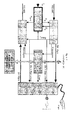
- Type P devices perform the functions of extracting / inserting both the signalling messages and the traffic information from / to the packets sent over the subscriber terminal lines, according to the working principle described above, being the solution currently preferred for the realization of such devices described by Fig. 2 and being such solution characterized by the implementation choices described below.
- the traffic information and the signalling messages transmitted from device S to device P as outbound multiplex signals will be demutiplexed by device P which, by using the "Time Mark” received messages will reconstruct the system time base and, consequently, the received superframe counting.
- Device P will use the superframe counting R p to generate the code blocks K p and K (p+2) necessary to encrypt or decrypt the superframe contents and, more specifically, to decrypt the 8 traffic information samples contained within the received packets and to encrypt the 8 traffic information samples to be inserted into the transmitted packets.
- the traffic information received in the multiplexed outbound packet corresponding to superframe of index R p will be decrypted by device P using the code block K p corresponding to the currently received superframe.
- the traffic information sent by device P to device S inside the multiplexed inbound packet destined to the superframe of index R p will be encrypted by using the code block K (p+2) corresponding to the superframe during which they will be decrypted.
- the signalling messages addressed to torminal device P will be used within the dialogue between user terminal and Call Server CS for incoming and outgoing call processing, according to the specific logic implemented in the system.
- Device P will contain a De-multiplex Unit (P-DX) which receives and processes the multiplexed outbound packets sent by device S, in order to extract from such packets both the signalling messages and the traffic information.
- P-DX De-multiplex Unit
- the above P-DX Unit in addition to the above described functions, will receive and process "Time Mark” messages in order to reconstruct the superframe timing and, consequently, the bit clock and byte clock synchronous with it.
- P-CU Management and Control Unit
- the above P-CU Unit will include a display device (to provide visual information to local user), a set of pushbuttons and switches (to receive criteria dealing with the call in progress from local user) and a ring generator (to call local user attention).
- a display device to provide visual information to local user
- a set of pushbuttons and switches to receive criteria dealing with the call in progress from local user
- a ring generator to call local user attention
- the above P-CU Unit will include a "service" input / output interface to handle 8 binary inputs and 8 binary outputs; such 8 binary inputs will be regularly read by the P-CU unit and their status will be transferred to the Call Server CS via a dedicated telemetry message, while the staus of the 8 binary outputs will be set by the P-CU Unit in accordance with the content of the telecontrol messages received by the Call Server CS.
- P-KU Crypto Sequence Generation Unit
- the P-KU Unit will generate and make available both the code block K p for decrypting the traffic information being currently received and the code block K (p+2) for encrypting the traffic information being currently transmitted.
- the above P-DX Unit after the multiplexed outbound packets have been received, will be able to use the code blocks provided by the P-KU Unit to decrypt the received traffic information and to provide such decrypted information as a digital signal at 64 Kbps together with the associated bit clock and byte clock.
- P-MX Multipexing Unit
- P-MX Multipexing Unit
- the above P-MX Unit will be able to use the code blocks provided by the P-KU unit to encrypt the traffic information to be transmitted and to provide such encrypted information as a set of 8 characters to be inserted into the multiplexed inbound packets.
- the P-KU Unit is implemented as plug-in unit of the terminal device P.
- P-AU Audio Unit
- P-AU Unit which is able to convert the traffic information received as a digital signal at 64 Kbps together with its bit clock and byte clock into the corresponding output signal in the audible band (300-3400 Hz).
- P-AU Unit will transform the digital signal corresponding to the decrypted traffic information provided by the P-DX Unit into an analogue signal in the audible band (300-3400 Hz).
- the same P-AU Unit will be able to convert the input signal in the audible band (300-3400 Hz) into a digital signal at 64 Kbps synchronous with the bit cock and byte clock received as timing reference inputs.
- analogue input / output signal of the P-AU Unit may be connected either to a local handset (part of the P-AU Unit) or, alternatively, to any external device via an appropriate I/O socket.
Landscapes
- Engineering & Computer Science (AREA)
- Computer Networks & Wireless Communication (AREA)
- Time-Division Multiplex Systems (AREA)
- Alarm Systems (AREA)
- Data Exchanges In Wide-Area Networks (AREA)
Applications Claiming Priority (1)
| Application Number | Priority Date | Filing Date | Title |
|---|---|---|---|
| ITRM20070311 ITRM20070311A1 (it) | 2007-06-05 | 2007-06-05 | Sistema di commutazione sicuro per voce e dati ad architettura modulare e distribuita |
Publications (2)
| Publication Number | Publication Date |
|---|---|
| EP2001260A2 true EP2001260A2 (de) | 2008-12-10 |
| EP2001260A3 EP2001260A3 (de) | 2010-08-18 |
Family
ID=39874894
Family Applications (1)
| Application Number | Title | Priority Date | Filing Date |
|---|---|---|---|
| EP08425390A Withdrawn EP2001260A3 (de) | 2007-06-05 | 2008-05-30 | Sicheres Schaltsystem für Sprache und Daten mit einer modularen verteilten Architektur |
Country Status (2)
| Country | Link |
|---|---|
| EP (1) | EP2001260A3 (de) |
| IT (1) | ITRM20070311A1 (de) |
-
2007
- 2007-06-05 IT ITRM20070311 patent/ITRM20070311A1/it unknown
-
2008
- 2008-05-30 EP EP08425390A patent/EP2001260A3/de not_active Withdrawn
Non-Patent Citations (1)
| Title |
|---|
| None |
Also Published As
| Publication number | Publication date |
|---|---|
| ITRM20070311A1 (it) | 2008-12-06 |
| EP2001260A3 (de) | 2010-08-18 |
Similar Documents
| Publication | Publication Date | Title |
|---|---|---|
| US4802220A (en) | Method and apparatus for multi-channel communication security | |
| EP1161806B1 (de) | Schlüsselverwaltung für telephonanrufe zum schutz von signalisierungs- und anrufpaketen zwischen cta's | |
| US5003593A (en) | Teleconferencing method for a secure key management system | |
| JPS63114399A (ja) | 電話通信システム | |
| GB2156631A (en) | Combined telecommunications and data communications systems | |
| US6577623B1 (en) | Fixed-length cell data and time-division data hybrid multiplexing apparatus | |
| US3989892A (en) | Line concentrator for dealing with asynchronous and synchronous data signals in a common bit format for a time division data switching exchange | |
| KR20000065144A (ko) | Pacs 무선기술을 특징으로 하는 유무선 액세스용 통합 원격통신 시스템 아키텍쳐 | |
| WO1999065269A1 (en) | System for transmitting data between circuit boards in a housing | |
| KR100197898B1 (ko) | 비동기식 전송모드 사설망의 음성전화 서비스장치 | |
| EP2001260A2 (de) | Sicheres Schaltsystem für Sprache und Daten mit einer modularen verteilten Architektur | |
| EP0784905B1 (de) | Kommunikationssystem | |
| KR100246535B1 (ko) | 디지털 트렁크 정합부에서의 암호화/복원 회로 | |
| KR100276626B1 (ko) | 비동기전송모드 공중망에서 인터워킹기능의 성능향상을 위한 신호처리방법 | |
| JP2563921B2 (ja) | 秘話通信方式 | |
| KR960015602B1 (ko) | 스위칭 기능을 가진 광 케이블 티.브이(catv) 분배센터용 협대역 종합정보 통신망 프레임 맵핑/디맵핑 장치 | |
| JP2687705B2 (ja) | ディジタル伝送方式 | |
| US5485454A (en) | System and method of communication between circuit mode communication installation core units | |
| KR0150284B1 (ko) | Cdma 이동통신 시스템의 무선 데이터통신 연동장치 | |
| JPS61278256A (ja) | 構内電子交換機の暗号付与方式 | |
| NO162098B (no) | Fremgangsmaate for overfoering av tale og data. | |
| JP2711468B2 (ja) | ディジタル通信網における特定機器判別方式 | |
| KR100270442B1 (ko) | 종합정보통신망 접속채널 선택기능을 구비한 중계장치 | |
| US20010036186A1 (en) | Method and device for facilitating audio and data transmission in a networked environment | |
| WO1999049630A1 (en) | Real-time audio to data and data to audio converter and method |
Legal Events
| Date | Code | Title | Description |
|---|---|---|---|
| PUAI | Public reference made under article 153(3) epc to a published international application that has entered the european phase |
Free format text: ORIGINAL CODE: 0009012 |
|
| AK | Designated contracting states |
Kind code of ref document: A2 Designated state(s): AT BE BG CH CY CZ DE DK EE ES FI FR GB GR HR HU IE IS IT LI LT LU LV MC MT NL NO PL PT RO SE SI SK TR |
|
| AX | Request for extension of the european patent |
Extension state: AL BA MK RS |
|
| PUAL | Search report despatched |
Free format text: ORIGINAL CODE: 0009013 |
|
| AK | Designated contracting states |
Kind code of ref document: A3 Designated state(s): AT BE BG CH CY CZ DE DK EE ES FI FR GB GR HR HU IE IS IT LI LT LU LV MC MT NL NO PL PT RO SE SI SK TR |
|
| AX | Request for extension of the european patent |
Extension state: AL BA MK RS |
|
| 17P | Request for examination filed |
Effective date: 20110128 |
|
| AKX | Designation fees paid |
Designated state(s): AT BE BG CH CY CZ DE DK EE ES FI FR GB GR HR HU IE IS IT LI LT LU LV MC MT NL NO PL PT RO SE SI SK TR |
|
| 17Q | First examination report despatched |
Effective date: 20120918 |
|
| STAA | Information on the status of an ep patent application or granted ep patent |
Free format text: STATUS: THE APPLICATION IS DEEMED TO BE WITHDRAWN |
|
| 18D | Application deemed to be withdrawn |
Effective date: 20121201 |