EP2001205A9 - Mobile communication terminal - Google Patents
Mobile communication terminal Download PDFInfo
- Publication number
- EP2001205A9 EP2001205A9 EP07738213A EP07738213A EP2001205A9 EP 2001205 A9 EP2001205 A9 EP 2001205A9 EP 07738213 A EP07738213 A EP 07738213A EP 07738213 A EP07738213 A EP 07738213A EP 2001205 A9 EP2001205 A9 EP 2001205A9
- Authority
- EP
- European Patent Office
- Prior art keywords
- display
- area
- display screen
- long state
- state
- Prior art date
- Legal status (The legal status is an assumption and is not a legal conclusion. Google has not performed a legal analysis and makes no representation as to the accuracy of the status listed.)
- Ceased
Links
Images


Classifications
-
- G—PHYSICS
- G06—COMPUTING; CALCULATING OR COUNTING
- G06F—ELECTRIC DIGITAL DATA PROCESSING
- G06F1/00—Details not covered by groups G06F3/00 - G06F13/00 and G06F21/00
- G06F1/16—Constructional details or arrangements
- G06F1/1613—Constructional details or arrangements for portable computers
- G06F1/1615—Constructional details or arrangements for portable computers with several enclosures having relative motions, each enclosure supporting at least one I/O or computing function
- G06F1/1622—Constructional details or arrangements for portable computers with several enclosures having relative motions, each enclosure supporting at least one I/O or computing function with enclosures rotating around an axis perpendicular to the plane they define or with ball-joint coupling, e.g. PDA with display enclosure orientation changeable between portrait and landscape by rotation with respect to a coplanar body enclosure
-
- H—ELECTRICITY
- H04—ELECTRIC COMMUNICATION TECHNIQUE
- H04B—TRANSMISSION
- H04B1/00—Details of transmission systems, not covered by a single one of groups H04B3/00 - H04B13/00; Details of transmission systems not characterised by the medium used for transmission
- H04B1/38—Transceivers, i.e. devices in which transmitter and receiver form a structural unit and in which at least one part is used for functions of transmitting and receiving
- H04B1/40—Circuits
-
- H—ELECTRICITY
- H04—ELECTRIC COMMUNICATION TECHNIQUE
- H04M—TELEPHONIC COMMUNICATION
- H04M1/00—Substation equipment, e.g. for use by subscribers
- H04M1/02—Constructional features of telephone sets
- H04M1/0202—Portable telephone sets, e.g. cordless phones, mobile phones or bar type handsets
- H04M1/0206—Portable telephones comprising a plurality of mechanically joined movable body parts, e.g. hinged housings
- H04M1/0208—Portable telephones comprising a plurality of mechanically joined movable body parts, e.g. hinged housings characterized by the relative motions of the body parts
- H04M1/0225—Rotatable telephones, i.e. the body parts pivoting to an open position around an axis perpendicular to the plane they define in closed position
- H04M1/0233—Including a rotatable display body part
-
- H—ELECTRICITY
- H04—ELECTRIC COMMUNICATION TECHNIQUE
- H04M—TELEPHONIC COMMUNICATION
- H04M1/00—Substation equipment, e.g. for use by subscribers
- H04M1/02—Constructional features of telephone sets
- H04M1/0202—Portable telephone sets, e.g. cordless phones, mobile phones or bar type handsets
- H04M1/0206—Portable telephones comprising a plurality of mechanically joined movable body parts, e.g. hinged housings
- H04M1/0247—Portable telephones comprising a plurality of mechanically joined movable body parts, e.g. hinged housings comprising more than two body parts
-
- H—ELECTRICITY
- H04—ELECTRIC COMMUNICATION TECHNIQUE
- H04M—TELEPHONIC COMMUNICATION
- H04M1/00—Substation equipment, e.g. for use by subscribers
- H04M1/02—Constructional features of telephone sets
- H04M1/0202—Portable telephone sets, e.g. cordless phones, mobile phones or bar type handsets
- H04M1/0206—Portable telephones comprising a plurality of mechanically joined movable body parts, e.g. hinged housings
- H04M1/0208—Portable telephones comprising a plurality of mechanically joined movable body parts, e.g. hinged housings characterized by the relative motions of the body parts
- H04M1/0214—Foldable telephones, i.e. with body parts pivoting to an open position around an axis parallel to the plane they define in closed position
Abstract
Description
- The present invention relates to a mobile communication terminal, and more particularly, to improvement of a communication terminal such as a cellular phone of which a display casing is rotatably held with respect to an operation casing such that a display screen can undergo a transition between a vertically long state and a horizontally long state.
- There is known a cellular phone including: a display casing having a display screen; operation casing having operation keys; and connecting means adapted to connect the both casings to each other, wherein the display casing is rotatably held in a plane parallel to the display screen relative to the operation casing.
- In such a cellular phone, switching between a vertically long state in which a longer direction of the display screen is made vertical and a horizontally long state in which the longer direction is made horizontal by rotating the display casing can be performed to use the phone.
- Patent Document 1: Japanese Unexamined Patent Publication No.
1991-250360 - Patent Document 2: Japanese Unexamined Patent Publication No.
1998-26964 - Patent Document 3: Japanese Unexamined Patent Publication No.
1998-49334 - Patent Document 4: Japanese Unexamined Patent Publication No.
2005-241652 - In a conventional manner, pictograms indicating a radio wave reception condition and a remaining battery level are displayed in a display area in an upper end portion of the display screen, and icons indicating function assignments assigned to operation keys are displayed in a display area in a lower end portion of the display screen. For this reason, if the display screen undergoes a transition from the vertically long state to the horizontally long state, the above respective display areas are horizontally extended, and therefore there arises a problem that a display area for displaying images and the like is narrowed.
- The present invention is made in consideration of the above situation, and an object thereof is to provide a mobile communication terminal of which the display area for displaying images and the like is inhibited from narrowing when a state of the display screen is switched from the vertically long state to the horizontally long state.
- A mobile communication terminal according to a first aspect of the present invention is one including: a display casing having a display screen; an operation casing having operation keys; and connecting means adapted to connect the display casing and the operation casing and rotatably hold the display casing with respect to the operation casing such that the display screen can undergo a transition between a vertically long state and a horizontally long state, and configured to include: connecting state detecting means adapted to detect a state of connection by the connecting means and determine whether the display screen is in the vertically long state or the horizontally long state; display object storage means adapted to store first and second display objects to be displayed depending on an operating state; and display controlling means adapted to display the respective display objects on the display screen. On a basis of a result of the determination by the connecting state detecting means, the display controlling means displays, in the case where the display screen is in the vertically long state, two or more of the first display objects in a first object display area provided in an upper end portion of the display screen, and two or more of the second display objects in a second object display area provided in an lower end portion of the display screen, or in the case where the display screen is in the horizontally long state, the respective first and second display objects in a third object display area provided in any of an upper end portion or a lower end portion of the display screen.
- In the mobile communication terminal, it is determined whether the display screen is in the vertically long state or the horizontally long state, and on a result of the determination, the respective display objects are displayed on the display screen. At this time, if the display screen is in the horizontally long state, the first and second display objects are displayed in the third object display area provided in any of the upper or lower end portion of the display screen. Based on such configuration, in the horizontally long state of the display screen, the respective display objects are arranged in one and the same object display area, so that the display area for displaying images and the like can be inhibited from narrowing when the state of the display screen is switched from the vertically long state to the horizontally long state.
- Note that the display objects herein refer to objects to be displayed, such as characters and images to be displayed on the display screen. Specifically, pictograms indicating a radio wave reception condition and a remaining battery level, icons indicating function assignments assigned to the operation keys, a character string indicating a source, and the like are included in the display objects.
- A mobile communication terminal according to a second aspect of the present invention is configured such that, in addition to the above-described configuration, the display controlling means sections the third object display area into first and second divided areas, and displays the respective first display objects in the first divided area including a continuous area having an area width larger than that of the second divided area.
- A mobile communication terminal according to a third aspect of the present invention is configured such that, in addition to the above-described configuration, the area width of the first divided area coincides with that of the first object display area.
- A mobile communication terminal according to a fourth aspect of present invention is configured such that, in addition to the above-described configuration, a character string displayed in the first object display area as the first display object in the vertically long state is displayed in the first divided area in the horizontally long state. Based on such configuration, the character string as the first display object is displayed in the first divided area including the continuous area having the area width larger than that of the second divided area, and therefore uncomfortable feeling can be inhibited from arising when the state of the display screen is switched from the vertically long state to the horizontally long state during the display of the character string.
- A mobile communication terminal according to a fifth aspect of present invention includes, in addition to the above-described configuration, source object generating means adapted to generate a source display object including a character string indicating a source upon incoming or calling, and is configured such that the display controlling means displays the source display object in the first object display area in the vertically long state, or in the first divided area in the horizontally long state.
- A mobile communication terminal according to a sixth aspect of the present invention is configured such that, in addition to the above-described configuration, the display controlling means provides a marquee display of the source display object.
- A mobile communication terminal according to a seventh aspect of the present invention is configured such that, in addition to the above-described configuration, the display controlling means sections a same row to provide the first and second divided areas.
- A mobile communication terminal according to an eighth aspect of the present invention is configured such that, in addition to the above-described configuration, the respective second display objects are icons indicating function assignments respectively assigned to the operation keys, and the display controlling means sections the third object display area into the first and second divided areas; and displays the respective first objects in the first divided area including a continuous area and the respective second display objects in the second divided areas separated left and right so as to sandwich the first divided area. Based on such configuration, the respective second display objects as the icons are displayed in the second divided areas separated left and right so as to sandwich the first divided area, and therefore can be easily associated with the left and right operation keys.
- A mobile communication terminal according to a ninth aspect of the present invention is configured such that, in addition to the above-described configuration, the display controlling means provides the third object display area in the lower end portion of the display screen.
- Based on the mobile communication terminal according to the present invention, in the horizontally long state of the display screen, the respective display objects are arranged in one and the same object display area, and therefore the display area for displaying images and the like can be inhibited from narrowing when the state of the display screen is switched from the vertically long state to the horizontally long state.
-
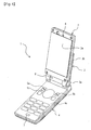
Fig. 1 is a perspective view illustrating an example of a schematic configuration of a mobile communication terminal according to an embodiment of the present invention, in which a foldablecellular phone 1 is illustrated as an example of the mobile communication terminal. Thecellular phone 1 includes: adisplay casing 2 having adisplay screen 2a; anoperation casing 4 havingoperation keys 4a, and 5a to 5c; and ahinge part 3 for connecting thedisplay casing 2 and theoperation casing 4 to each other, and both of the casings can be folded with thedisplay screen 2a and an operating surface of theoperation casing 4 being made to face to each other. Note thatFig. 1 illustrates thecellular phone 1 with the both casings being expanded. - The
display casing 2 is arranged with thedisplay screen 2a and areceiver 8 on a surface thereof facing to the operating surface of theoperation casing 4 in a folded state. Thedisplay screen 2a is an output part for characters and images, and formed in a rectangular shape. Here, thedisplay screen 2a is arranged such that a longer direction thereof corresponds to that of thedisplay casing 2. Thereceiver 8 is a voice output part upon calling, and arranged at an end part on a side opposite to thehinge part 3 in thedisplay casing 2. - The
operation casing 4 is arranged with a plurality ofoperation keys 4a, and 5a to 5c, and a transmittingmicrophone 7 on a surface thereof facing to thedisplay screen 2a of thedisplay casing 2 in the folded state. Theoperation keys 4a include ten keys, on-hook key, off-hook key, and the like, and are arranged on a side opposite to thehinge part 3 in theoperation casing 4. - The operation keys 5a to 5c are ones for displaying icons indicating function assignments on the
display screen 2a, and referred to as guide keys, function keys, soft keys, or the like. The respective operation keys 5a to 5c are arranged on thehinge part 3 side in theoperation casing 4. - We here assume that, as such operation keys, a menu key 5a, an
end key 5b, and a direction key 5c are provided. The menu key 5a is an operation key for displaying a menu screen, and arranged on the left side of theoperation casing 4. Theend key 5b is an operation key for quitting a running application program. The direction key 5c is a multi-function key by which input depends on a press-down position, and can vertically and horizontally move a cursor position or the like. The transmittingmicrophone 7 is a voice input part upon calling, and arranged at an end part on a side opposite to thehinge part 3 in theoperation casing 4. - The
hinge part 3 includes: a connectingpart 3a provided so as to be rotationally movable with respect to theoperation casing 4; and aholding part 3b for holding thedisplay casing 2. The connectingpart 3a includes two cylindrical bodies formed at one end part of theholding part 3b so as to project at a certain interval between each other. At one end part in a longer direction on an inner surface of theoperation casing 4, acylindrical body 6 is formed so as to extend in a direction perpendicular to the longer direction, and thecylindrical body 6 is coaxially arranged between the respective cylindrical bodies of the connectingpart 3a. By rotationally moving thehinge part 3 with respect to theoperation casing 4, the terminal can be folded. - The
holding part 3b is adapted to rotatably hold thedisplay casing 2 in a plane parallel to thedisplay screen 2a, and thedisplay casing 2 is adapted to rotate with an inclination angle to theoperation casing 4 being kept. That is, thehinge part 3 is means adapted to make a connection between thedisplay casing 2 and theoperation casing 4, and rotatably hold thedisplay casing 2 with respect to theoperation casing 4 such that thedisplay screen 2a can undergo a transition between a vertically long state and a horizontally long state. - Such a folding type
cellular phone 1 can be carried with being compactly folded, and when the casings are expanded, theoperation keys 4a, and 5a to 5c can be operated while viewing a display on adisplay screen 2a. Also, thecellular phone 1 is adapted to enable a call in an excellent condition with a mouth being brought close to the transmittingmicrophone 7 and an ear being brought close to thereceiver 8 by bringing thedisplay screen 2a into the vertically long state as illustrated inFig. 1 , and placing the ear against an inner surface of thedisplay casing 2. -
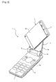
Fig. 2 is a perspective view illustrating a state where thedisplay casing 2 in thecellular phone 1 ofFig. 1 is rotated with respect to theoperation casing 4, in which a state where thedisplay casing 4 is rotated clockwise from the state illustrated inFig. 1 by approximately 45 degrees as viewed from the front is illustrates.Fig. 3 is a perspective view illustrating a state where thedisplay casing 2 of thecellular phone 1 inFig. 1 is rotated, and illustrates the state where thedisplay casing 2 is rotated clockwise from the state illustrated inFig. 1 by 90 degrees as viewed from the front. - A user can switch between the vertically long state illustrated in
Fig. 1 and the horizontally long state illustrated inFig. 3 by rotating thedisplay casing 2 while grasping theoperation casing 4. That is, by rotating thedisplay casing 2 from the vertically long state illustrated inFig. 1 , the user can make thedisplay screen 2a undergo a transition to the horizontally long state as illustrated inFig. 3 through the state illustrated inFig. 2 : - When the user watches a TV broadcast, he/she can display TV images in accordance with an aspect ratio of the TV images by switching the
display screen 2a to the horizontally long state. That is, a ratio between long and short sides of thedisplay screen 2a is 16:9, which corresponds to the aspect ratio of the TV images used for the typical TV broadcast. - In a case where the
display casing 2 is rotated clockwise from the state illustrated inFig. 1 , it is adapted such that a biasing force acts on thedisplay casing 2 anticlockwise by biasing means provided inside theholding part 3b of thehinge part 3 until the state illustrated inFig. 2 is reached. Accordingly, in the state illustrated inFig. 1 , thedisplay casing 2 is adapted to be kept in the state illustrated inFig. 1 by the biasing force acting on thedisplay casing 2 anticlockwise unless an external force acts. - On the other hand, if the
display casing 2 is further rotated clockwise from the state illustrated inFig. 2 , the biasing force acting on thedisplay casing 2 is switched to a clockwise force, and then thedisplay casing 2 is locked in the state illustrated inFig. 3 . Based on this, thedisplay casing 2 is adapted to be kept in the state illustrated inFig. 3 unless the external force acts. - In the present embodiment, the
display casing 2 does not rotate around a rotary axis fixed at a certain position, but is adapted to rotate around a rotary axis moving with the rotation of thedisplay casing 2. Based on this, even if thedisplay casing 2 in the vertically long state in which one end part in the longer direction is close to theoperation casing 4 as illustrated inFig. 1 is rotated by 90 degrees, it is adapted such that one end part in a direction perpendicular to the longer direction of thedisplay casing 2 is brought close to theoperation casing 4 as illustrated inFig. 3 , and the TV images can be displayed on thedisplay screen 2a having been compactly brought into the horizontally long state to watch the TV broadcast. - Also, by rotating the
display casing 2 from the vertically long state to the horizontally long state while grasping theoperation casing 4, the TV broadcast can be watched without shifting thecellular phone 1 from one hand to the other. At this time, thedisplay casing 2 is adapted to be able to be smoothly switched between the vertically long state and the horizontally long state by the biasing force acting on thedisplay casing 2. -
Fig. 4 is a block diagram illustrating an example of a functional configuration inside thecellular phone 1 ofFig. 1 . Thecellular phone 1 includesantennas cellular communication part 11, a TVbroadcast receiving part 12, anoperation input part 13, aspeaker 14, adisplay controlling part 16, anLCD 17, a connectingstate detecting part 18, a sourceobject generating part 19, and a displayobject storage part 20, in addition to the above-describedreceiver 8 and transmittingmicrophone 7, and operations of them are controller by amain control part 15 including a processor. - The
speaker 14 is a voice output part, and can amplify voice to output it louder than a case where it is outputted from thereceiver 8. This enables the voice to be heard even with the ear being apart from thedisplay casing 2. - The
receiver 8 is used with the user placing the user's ear against an inner surface of thedisplay casing 2, whereas thespeaker 14 is used with the user setting the user's ear apart from the inner surface of thedisplay casing 2. Accordingly, the display of TV images and the like on thedisplay screen 2a can be viewed while thespeaker 14 is used, but cannot be viewed while thereceiver 8 is used. - When the
speaker 14 is used to make a call with an opposite side telephone set, voice from the opposite side telephone set is amplified and then outputted from thespeaker 14, and an input signal from the transmittingmicrophone 7 is amplified, whereby a hands-free call can be made without grasping thecellular phone 1. At this time, the input signal from the transmittingmicrophone 7 is adapted to be inputted to a cancel circuit for preventing howling. Switching between the normal call using thereceiver 8 and the hands-free call can be performed by operating the operation keys. - The
cellular communication part 11 is mobile communication processing means adapted to transmit/receive a radio wave to/from a base station via theantenna 11a for communication. In a state where the call with the opposite side telephone set is established, a voice signal based on call voice of the user is transmitted from thecellular communication part 11, and a voice signal based on call voice from the opposite side telephone set is received by thecellular communication part 11, whereby the two types of call voice are transmitted and received in real time, respectively. - The TV
broadcast receiving part 12 is a tuner for receiving TV broadcast waves transmitted from a TV station via theantenna 12a for TV broadcast reception. The TV broadcast waves transmitted from the TV station include an analog broadcast wave corresponding to an analog broadcast and a digital broadcast wave corresponding to a digital broadcast. The digital broadcast wave received by the TVbroadcast receiving part 12 is a one-segment broadcast wave for cellular phones, which is allocated to a certain band for a general digital high-vision broadcast wave, and includes, in addition to TV images and TV voice, character information such as captions corresponding to the TV images and associated articles, channel information depending on a frequency band for the incoming radio wave. - On a basis of the TV broadcast wave received by the TV
broadcast receiving part 12, the TV images are displayed on thedisplay screen 2a, and various types of TV voice corresponding to the TV images are outputted from thespeaker 14, whereby the TV broadcast can be watched. Also, by extracting the character information included in the TV broadcast wave to display it on thedisplay screen 2a, the character information such as the captions can be displayed together with the TV images. Further, if the TV images and the various types of TV voice based on the TV broadcast wave are stored in a memory (not shown), the TV broadcast can be recorded. - The
operation input part 13 performs operations for generating input signals on the basis of operations of therespective operation keys 4a, and 5a to 5c. The connectingstate detecting part 18 performs operations for detecting a state of connection by thehinge part 3 to determine whether thedisplay screen 2a is in the vertically long state or the horizontally long state. Specifically, it includes a mechanical or electrical switch, and detects a rotating operation for adisplay casing 2 by the user to thereby sense a rotational position of thedisplay casing 2. - The display
object storage part 20 is a nonvolatile memory, in which first and second display objects to be displayed depending on an operating state are stored. Specifically, pictograms and the like indicating a radio wave reception condition (reception intensity), a remaining battery level, and an incoming mail are stored as the first display objects, and icons and the like indicating the function assignments assigned to the operation keys 5a to 5c are stored as the second display objects. - The above pictograms are not affected by a screen display based on the other application program, but are display objects constantly displayed on the
display screen 2a. As the above icons, a menu icon associated with the menu key 5a, and an end icon associated with the end key 5b are stored as the display objects. - The source object generating
part 19 performs operations for generating source display objects each including a character string indicating a source upon incoming or calling. Specifically, source phone numbers, pre-registered user names, and the like are generated as the display objects indicating the sources. - The LCD (Liquid Crystal Display) 17 is a display device having the
display screen 2a. Thedisplay controlling part 16 performs operations for controlling theLCD 17 to display characters and images on thedisplay screen 2a. Specifically, the respective display objects are displayed on thedisplay screen 2a on the basis of a result of the determination by the connectingstate detecting part 18. That is, if thedisplay screen 2a is in the vertically long state, a plurality of first display objects are displayed in a first object display area provided in an upper end portion of thedisplay screen 2a, and a plurality of second display objects are displayed in a second object display area provided in a lower end portion of thedisplay screen 2a. On the other hand, if thedisplay screen 2a is in the horizontally long state, the respective first and second display objects are displayed in a third object display area provided in a lower end portion of thedisplay screen 2a. - We here assume that the third object display area is sectioned into first and second divided areas, and the respective first display objects are displayed in the first divided area including a continuous area having an area width larger than that of the second divided area. We also assume that a character string displayed in the first object display area as the first display object in the vertically long state is displayed in the first divided area in the horizontally long state.
-
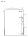
Figs. 5 (a) and (b) are diagrams illustrating an example of operations in thecellular phone 1 ofFig. 1 , and inFig. 5 (a) , an appearance of thedisplay screen 2a in the vertically long state is illustrated, whereas, inFig. 5 (b) , an appearance of thedisplay screen 2a in the horizontally long state is illustrated. In the vertically long state, a display area is vertically extended as compared with horizontally, as viewed from the user. In such a vertically long state, the firstobject display area 21 is provided in the upper end portion of thedisplay screen 2a, and a secondobject display area 23 is provided in the lower end portion. - An area between the first
object display area 21 and the secondobject display area 23 is adisplay area 22 for images and the like. - We here assume that the first
object display area 21 is provided such that a height of a row for displaying a character string coincides with that of the area, and arranged adjacent to a short side of thedisplay screen 2a. In this example, thepictograms 24a to 24c are displayed in the firstobject display area 21, and theicons object display area 23. - The
pictogram 24a is a display object for indicating a radio wave reception intensity, and arranged at a left end part. Thepictogram 24b is a display object for indicating the incoming of an electronic mail. Thepictogram 24c is a display object for indicating the remaining battery level, and arranged at a right end part. - The
icon 25a is the menu icon, and a symbol like an operation button is displayed as the menu icon. Theicon 25a is arranged at the left end part. Theicon 25b is the end icon, and a symbol like an operation button is displayed as the end icon. Theicon 25b is arranged at the right end part. - On the other hand, in the horizontally long state, the display area is horizontally extended as compared with vertically, as viewed from the user. In such a horizontally long state, the third
object display area 32 is provided in the lower end portion of thedisplay screen 2a. An area other than the thirdobject display area 32 is adisplay area 31 for images and the like. - We here assume that the third
object display area 32 is provided such that a height of a row for displaying a character string coincides with that of the area, and arranged adjacent to the long side of thedisplay screen 2a. The thirdobject display area 32 is sectioned into the first dividedarea 34 and the second dividedareas area 34 including the continuous area having an area width A3 larger than those of the second dividedareas area 34 to the object display area in the vertically long state (area width: A1) is small, as compared with that of the second dividedareas 33 and 35 (area width: A2 + A4). - We here assume that the
respective display areas 33 to 35 are provided by sectioning the same row. That is, assumed is that heights of theicons pictograms 24a to 24c, and character strings are aligned to display the respective display objects. - The first display objects 24a to 24c are displayed in the first divided
area 34 in a same order as that in the vertically long state. This enables the first display objects to be recognized without uncomfortable feeling when the state of thedisplay screen 2a is switched from the vertically long state to the horizontally long state, because an arrangement order of therespective pictograms 24a to 24c is unchanged before and after the state transition. - The second display objects 25a and 25b are respectively displayed in the second divided
areas icons respective operation keys 5a and 5b arranged left and right are displayed in thedisplay area 33 on the left side and thedisplay area 35 on the right side, respectively. Specifically, theicon 25a is arranged on the left side, and theicon 25b on the right side. - In this example, the area width A3 of the first divided
area 34 coincides with the area width A1 of the firstobject display area 21. That is, the first dividedarea 34 is formed such that the horizontal length thereof is not different from those of the respectiveobject display areas display screen 2a is switched from the vertically long state to the horizontally long state, because the display area for thepictograms 24a to 24c just goes down from the firstobject display area 21 to the thirdobject display area 32 without modification. Note that the area width A3 of the first dividedarea 34 may be made larger than the area width A1. - Also, by providing the third
object display area 32 in the lower end portion of thedisplay screen 2a, operability can be improved even in the horizontally long state, similarly to the vertically long state, because the positions of the second display objects are close to the respective operation keys 5a to 5c on theoperation casing 4. In particular, by respectively arranging theicons display area 33 on the left side and thedisplay area 35 on the right side, the uncomfortable feeling can be inhibited from arising when the state of thedisplay screen 2a is switched from the vertically long state to the horizontally long state. -
Fig. 6 is a diagram illustrating an example of the operations in thecellular phone 1 ofFig. 1 , and illustrates an appearance of thedisplay screen 2a upon incoming or calling. In the case where thedisplay screen 2a is in the horizontally long state, thesource display object 41 including a character string indicating a source is displayed in the thirdobject display area 32 upon incoming or calling. - Specifically, a source phone number or a user name is displayed in the first divided
area 34 as thesource display object 41. Thesource display object 41 is statically or dynamically displayed in the horizontal direction as a direction of the character string. The static display includes a so-called ticker display in which a character string having a certain number of characters as an upper limit is displayed in a given display area. The dynamic display includes a so-called marquee display in which a character string is displayed as if it flows in one direction from one end to the other end in a given display area while varying a display position of the characters. - Steps S101 to S105 in
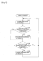
Fig. 7 represent a flowchart illustrating an example of the operations in thecellular phone 1 ofFig. 1 . First, the connectingstate detecting part 18 detects a connecting state of the hinge part 3 (Step S101). Then, thedisplay controlling part 16 changes arrangement of the first and second display objects if the state of thedisplay screen 2a is switched from the vertically long state to the horizontally long state (Steps S102 and S103). At this time, thepictograms 24a to 24c andicons object display area 32. - On the other hand, if the state of the
display screen 2a is switched from the horizontally long state to the vertically long state, the arrangement of the first and second display objects is changed (Steps S104 and S105). At this time, thepictograms 24a to 24c are arranged in the firstobject display area 21, and theicons object display area 23. - According to the present embodiment, in the horizontally long state of the
display screen 2a, the respective display objects are arranged in one and the sameobject display area 32, so that thedisplay area 31 for displaying images and the like can be inhibited from narrowing when the state of thedisplay screen 2a is switched from the vertically long state to the horizontally long state. - Note that, in the present embodiment, the case where the third object display area is provided in the lower end portion of the
display screen 2a is described as an example; however, the present invention is not limited to this. For example, the third object display area may be provided in an upper end portion of thedisplay screen 2a. -
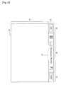
Fig. 8 is a diagram illustrating another embodiment of the present invention, in which an appearance of thedisplay screen 2a in the horizontally long state is illustrated. In this example, a thirdobject display area 51 is provided in the upper end portion of thedisplay screen 2a. An area other than the thirdobject display area 51 is adisplay area 52 for images and the like. - Also, the third
object display area 51 is sectioned into a first dividedarea 54, and second dividedareas 53 and 55, and in therespective display areas 53 to 55, the respective display objects are arranged. Even by such a configuration, thedisplay area 52 for displaying images and the like can be inhibited from narrowing when the state of thedisplay screen 2a is switched from the vertically long state to the horizontally long state, because the respective display objects are arranged in one and the sameobject display area 51 in the horizontally long state of thedisplay screen 2a. - Note that, in the present embodiment, the case where the respective second display objects are displayed in the second divided
areas area 34 is described as an example; however, the present invention is not limited to this. For example, the third object display area may be sectioned into two continuous areas to display the first display objects in one of the continuous areas as the first divided area, and the second display objects in the other one of the continuous areas as the second divided area. -
Fig. 9 is a diagram illustrating still another embodiment of the present invention, in which an appearance of thedisplay screen 2a in the horizontally long state is illustrated. In this example, a thirdobject display area 62 is sectioned into two continuous areas, i.e., adisplay area 63 on the left side and adisplay area 64 on the right side, and the respective display objects are arranged in the respective display areas. Adisplay area 61 is one for images and the like. - Specifically, the
pictograms 24a to 24c are arranged in thedisplay area 63 on the left side, and theicons display area 64 on the right side. Thedisplay area 63 on the left side is adapted to be the first divided area, and thedisplay area 64 on the right side to be the second divided area. Thedisplay area 63 on the left side includes an area of which an area width B1 is larger than an area width B2 of thedisplay area 64 on the right side, and in the area, the respective first display objects are displayed. That is, a ratio of change of thedisplay area 63 on the left side to the object display area (area width A1) in the vertically long state is small, as compared with that of thedisplay area 64 on the right side. Even by such a configuration, thedisplay area 61 for displaying images and the like can be inhibited from narrowing when the state of thedisplay screen 2a is switched from the vertically long state to the horizontally long state, because the respective display objects are arranged in one and the sameobject display area 62 in the horizontally long state of thedisplay screen 2a. - The present application claims the Paris convention priority of the patent application filed on March 28, 2006 , in Japan (Japanese Patent Application No.
2006-87357 -
- [
Fig. 1] Fig. 1 is a perspective view illustrating an example of a schematic configuration of a mobile communication terminal according to an embodiment of the present invention, in which a foldablecellular phone 1 is illustrated as an example of the mobile communication terminal. - [
Fig. 2] Fig. 2 is a perspective view illustrating a state where thedisplay casing 2 in thecellular phone 1 ofFig. 1 is rotated with respect to theoperation casing 4. - [
Fig. 3] Fig. 3 is a perspective view illustrating a state where thedisplay casing 2 of thecellular phone 1 inFig. 1 is rotated, in which the state where thedisplay casing 4 is rotated clockwise from the state illustrated inFig. 1 by 90 degrees as viewed from the front is illustrated. - [
Fig. 4] Fig. 4 is a block diagram illustrating an example of a functional configuration inside thecellular phone 1 ofFig. 1 . - [
Fig. 5] Fig. 5 is a diagram illustrating an example of operations in thecellular phone 1 ofFig. 1 . - [
Fig. 6] Fig. 6 is a diagram illustrating an example of the operations in thecellular phone 1 ofFig. 1 , in which an appearance of thedisplay screen 2a upon incoming or calling is illustrated. - [
Fig.7] Fig. 7 is a flowchart illustrating an example of the operations in thecellular phone 1 ofFig. 1 . - [
Fig. 8] Fig. 8 is a diagram illustrating another embodiment of the present invention, in which an appearance of thedisplay screen 2a in a horizontally long state is illustrated. - [
Fig. 9] Fig. 9 is a diagram illustrating still another embodiment of the present invention, in which an appearance of thedisplay screen 2a in the horizontally long state is illustrated. -
- 1
- Cellular phone
- 2
- Display casing
- 2a
- Display screen
- 3
- Hinge part
- 3a
- Connecting part
- 3b
- Holding part
- 4a, 5a∼5c
- Operation keys
- 4
- Operation casing
- 7
- Transmitting microphone
- 8
- Receiver
- 11
- Cellular communication part
- 12
- TV broadcast receiving part
- 13
- Operation input part
- 14
- Speaker
- 15
- Main control part
- 16
- Display controlling part
- 17
- LCD
- 18
- Connecting state detecting part
- 19
- Source object generating part
- 20
- Display object storage part
Claims (9)
- A mobile communication terminal including: a display casing having a display screen; an operation casing having operation keys; and connecting means adapted to connect said display casing and said operation casing and rotatably hold said display casing with respect to said operation casing such that said display screen can undergo a transition between a vertically long state and a horizontally long state, the mobile communication terminal comprising:connecting state detecting means adapted to detect a state of connection by said connecting means and determine whether said display screen is in the vertically long state or the horizontally long state;display object storage means adapted to store first and second display objects to be displayed depending on an operating state; anddisplay controlling means adapted to display said respective display objects on said display screen, wherein,on a basis of a result of the determination by said connecting state detecting means, said display controlling means displays, in the case where said display screen is in the vertically long state, two or more of said first display objects in a first object display area provided in an upper end portion of the display screen, and two or more of said second display objects in a second object display area provided in an lower end portion of the display screen, and in the case where said display screen is in the horizontally long state, said respective first and second display objects in a third object display area provided in any of an upper end portion or a lower end portion of the display screen.
- The mobile communication terminal according to claim 1, wherein said display controlling means sections said third object display area into first and second divided areas, and displays said respective first display objects in said first divided area including a continuous area having an area width larger than that of said second divided area.
- The mobile communication terminal according to claim 2, wherein said area width of said first divided area coincides with an area width of said first object display area.
- The mobile communication terminal according to claim 2 or 3, wherein a character string displayed in said first object display area as said first display object in said vertically long state is displayed in said first divided area in said horizontally long state.
- The mobile communication terminal according to claim 2 or 3, comprising source object generating means adapted to generate a source display object including a character string indicating a source upon incoming or calling, wherein
said display controlling means displays said source display object in said first object display area in said vertically long state, or in said first divided area in said horizontally long state. - The mobile communication terminal according to claim 5, wherein said display controlling means provides a marquee display of said source display object.
- The mobile communication terminal according to claim 2, wherein said display controlling means sections a same row to provide said first and second divided areas.
- The mobile communication terminal according to claim 1, wherein said respective second display objects are icons indicating function assignments respectively assigned to said operation keys, and
said display controlling means sections said third object display area into first and second divided areas; and displays said respective first objects in said first divided area including a continuous area and said respective second display objects in said second divided areas separated left and right so as to sandwich said first divided area. - The mobile communication terminal according to claim 8, wherein said display controlling means provides said third object display area in the lower end portion of the display screen.
Applications Claiming Priority (2)
| Application Number | Priority Date | Filing Date | Title |
|---|---|---|---|
| JP2006087357 | 2006-03-28 | ||
| PCT/JP2007/054728 WO2007111112A1 (en) | 2006-03-28 | 2007-03-09 | Mobile communication terminal |
Publications (3)
| Publication Number | Publication Date |
|---|---|
| EP2001205A2 EP2001205A2 (en) | 2008-12-10 |
| EP2001205A9 true EP2001205A9 (en) | 2009-03-18 |
| EP2001205A4 EP2001205A4 (en) | 2011-05-04 |
Family
ID=38541033
Family Applications (1)
| Application Number | Title | Priority Date | Filing Date |
|---|---|---|---|
| EP07738213A Ceased EP2001205A4 (en) | 2006-03-28 | 2007-03-09 | Mobile communication terminal |
Country Status (8)
| Country | Link |
|---|---|
| US (1) | US8140125B2 (en) |
| EP (1) | EP2001205A4 (en) |
| JP (3) | JP4679637B2 (en) |
| KR (1) | KR101049364B1 (en) |
| CN (1) | CN101375580A (en) |
| BR (1) | BRPI0708933A2 (en) |
| TW (1) | TWI342145B (en) |
| WO (1) | WO2007111112A1 (en) |
Families Citing this family (6)
| Publication number | Priority date | Publication date | Assignee | Title |
|---|---|---|---|---|
| JP5248870B2 (en) * | 2008-01-24 | 2013-07-31 | 京セラ株式会社 | Terminal device with video display function |
| CN102109959A (en) * | 2011-03-07 | 2011-06-29 | 惠州Tcl移动通信有限公司 | Method for realizing rotation of JAVA application programming interface (API) with rotation of screen |
| JP5741136B2 (en) | 2011-03-30 | 2015-07-01 | 富士通株式会社 | Control program, control program for portable terminal and virtual machine |
| JP4960529B1 (en) * | 2011-10-14 | 2012-06-27 | 株式会社Osk | Display program for portable communication terminals |
| JP6006530B2 (en) * | 2012-05-18 | 2016-10-12 | 京セラ株式会社 | Electronics |
| JP6055699B2 (en) * | 2013-03-05 | 2016-12-27 | アイホン株式会社 | Nurse call system |
Family Cites Families (20)
| Publication number | Priority date | Publication date | Assignee | Title |
|---|---|---|---|---|
| JP2752496B2 (en) | 1990-02-28 | 1998-05-18 | キヤノン株式会社 | Sentence processing equipment |
| JP3603488B2 (en) | 1996-07-10 | 2004-12-22 | カシオ計算機株式会社 | Report menu display device |
| JP3906497B2 (en) | 1996-08-02 | 2007-04-18 | カシオ計算機株式会社 | Menu display device |
| KR100293997B1 (en) * | 1998-08-10 | 2001-07-12 | 윤종용 | Method for displaying status of cordless telephone set |
| KR100303793B1 (en) * | 1998-11-05 | 2001-11-22 | 윤종용 | Display device and display method of folder type communication terminal |
| JP2001156893A (en) * | 1999-11-29 | 2001-06-08 | Nec Saitama Ltd | Display system and its method for communication apparatus |
| KR100470172B1 (en) * | 2001-06-22 | 2005-02-04 | 주식회사 임팩트라 | Mobile Station having Display Part Convertible Vertical into Horizontal |
| JP2003174495A (en) * | 2001-09-28 | 2003-06-20 | Nec Corp | Folding portable information terminal |
| JP2003337644A (en) * | 2002-03-14 | 2003-11-28 | Sony Corp | Electronic device, program, program providing device and recording medium |
| JP4061473B2 (en) * | 2002-04-26 | 2008-03-19 | 日本電気株式会社 | Folding mobile phone |
| JP2004064716A (en) * | 2002-06-03 | 2004-02-26 | Toya Kensetsu Kogyo:Kk | Portable telephone set |
| JP4622223B2 (en) * | 2003-09-30 | 2011-02-02 | カシオ計算機株式会社 | Mobile phone |
| US20050091431A1 (en) * | 2003-10-23 | 2005-04-28 | Robert Olodort | Portable communication devices |
| JP4241337B2 (en) | 2003-11-21 | 2009-03-18 | カシオ計算機株式会社 | Mobile phone and display control program |
| KR100611182B1 (en) * | 2004-02-27 | 2006-08-10 | 삼성전자주식회사 | Portable electronic device for changing menu display state according to rotating degree and method thereof |
| US20070044028A1 (en) * | 2004-04-01 | 2007-02-22 | Dunn Michael H | Virtual flip chart method and apparatus |
| US7339600B2 (en) * | 2004-04-26 | 2008-03-04 | Samsung Electronics Co., Ltd. | Apparatus and method for displaying a picture in a wireless terminal |
| JP4197310B2 (en) * | 2004-04-28 | 2008-12-17 | シャープ株式会社 | Mobile phone |
| JP4319116B2 (en) | 2004-09-24 | 2009-08-26 | ダイワ精工株式会社 | Fishing spinning reel |
| US7474889B2 (en) * | 2005-08-30 | 2009-01-06 | International Business Machines Corporation | Informing wireless device users of incoming calls or pages in environments inhospitable for notification |
-
2007
- 2007-03-09 KR KR1020087018706A patent/KR101049364B1/en not_active IP Right Cessation
- 2007-03-09 US US12/294,415 patent/US8140125B2/en not_active Expired - Fee Related
- 2007-03-09 WO PCT/JP2007/054728 patent/WO2007111112A1/en active Application Filing
- 2007-03-09 BR BRPI0708933-3A patent/BRPI0708933A2/en not_active IP Right Cessation
- 2007-03-09 CN CNA2007800039103A patent/CN101375580A/en active Pending
- 2007-03-09 JP JP2008506861A patent/JP4679637B2/en not_active Expired - Fee Related
- 2007-03-09 EP EP07738213A patent/EP2001205A4/en not_active Ceased
- 2007-03-19 TW TW096109367A patent/TWI342145B/en not_active IP Right Cessation
-
2010
- 2010-12-08 JP JP2010273407A patent/JP4767359B2/en not_active Expired - Fee Related
-
2011
- 2011-04-21 JP JP2011094662A patent/JP4874427B2/en not_active Expired - Fee Related
Also Published As
| Publication number | Publication date |
|---|---|
| KR101049364B1 (en) | 2011-07-13 |
| JP4679637B2 (en) | 2011-04-27 |
| CN101375580A (en) | 2009-02-25 |
| JP4874427B2 (en) | 2012-02-15 |
| WO2007111112A1 (en) | 2007-10-04 |
| BRPI0708933A2 (en) | 2011-06-14 |
| JP4767359B2 (en) | 2011-09-07 |
| JPWO2007111112A1 (en) | 2009-08-06 |
| US20090170565A1 (en) | 2009-07-02 |
| TW200803412A (en) | 2008-01-01 |
| TWI342145B (en) | 2011-05-11 |
| US8140125B2 (en) | 2012-03-20 |
| EP2001205A4 (en) | 2011-05-04 |
| EP2001205A2 (en) | 2008-12-10 |
| JP2011091842A (en) | 2011-05-06 |
| KR20080088622A (en) | 2008-10-02 |
| JP2011217380A (en) | 2011-10-27 |
Similar Documents
| Publication | Publication Date | Title |
|---|---|---|
| JP4583344B2 (en) | Mobile phone | |
| EP2182704B1 (en) | Mobile telephone with television broadcast reception means | |
| US20030064688A1 (en) | Slide-type portable communication apparatus | |
| EP2001210A9 (en) | Mobile telephone | |
| JPWO2007105369A1 (en) | Mobile phone | |
| US8140125B2 (en) | Mobile communication terminal | |
| JP4404878B2 (en) | Mobile phone | |
| JP2005150936A (en) | Communications apparatus | |
| JP4667227B2 (en) | Mobile phone | |
| KR100365852B1 (en) | Cellular phone having dual lcd | |
| KR100476008B1 (en) | Mobile communication terminal having touch screen | |
| KR100747454B1 (en) | Mobile communication device having sub display device capable of direction control | |
| JP4243173B2 (en) | Method for using cellular phone and bone conduction speaker and program for using the same | |
| JP2008109688A (en) | Communications apparatus | |
| KR100594462B1 (en) | Mobile communication terminal having a SMS message update displaying function and controlling method therefore |
Legal Events
| Date | Code | Title | Description |
|---|---|---|---|
| PUAI | Public reference made under article 153(3) epc to a published international application that has entered the european phase |
Free format text: ORIGINAL CODE: 0009012 |
|
| 17P | Request for examination filed |
Effective date: 20080926 |
|
| AK | Designated contracting states |
Kind code of ref document: A2 Designated state(s): CH DE ES FR GB IT LI |
|
| PUAB | Information related to the publication of an a document modified or deleted |
Free format text: ORIGINAL CODE: 0009199EPPU |
|
| RBV | Designated contracting states (corrected) |
Designated state(s): CH DE ES FR GB IT LI |
|
| A4 | Supplementary search report drawn up and despatched |
Effective date: 20110401 |
|
| 17Q | First examination report despatched |
Effective date: 20111122 |
|
| DAX | Request for extension of the european patent (deleted) | ||
| REG | Reference to a national code |
Ref country code: DE Ref legal event code: R003 |
|
| STAA | Information on the status of an ep patent application or granted ep patent |
Free format text: STATUS: THE APPLICATION HAS BEEN REFUSED |
|
| 18R | Application refused |
Effective date: 20121018 |