EP2000874B1 - Failure-diagnosis information collection system - Google Patents
Failure-diagnosis information collection system Download PDFInfo
- Publication number
- EP2000874B1 EP2000874B1 EP08010384A EP08010384A EP2000874B1 EP 2000874 B1 EP2000874 B1 EP 2000874B1 EP 08010384 A EP08010384 A EP 08010384A EP 08010384 A EP08010384 A EP 08010384A EP 2000874 B1 EP2000874 B1 EP 2000874B1
- Authority
- EP
- European Patent Office
- Prior art keywords
- abnormality
- time
- preliminary
- stored
- instant
- Prior art date
- Legal status (The legal status is an assumption and is not a legal conclusion. Google has not performed a legal analysis and makes no representation as to the accuracy of the status listed.)
- Expired - Fee Related
Links
- 238000003745 diagnosis Methods 0.000 title claims description 139
- 230000005856 abnormality Effects 0.000 claims description 448
- 230000004044 response Effects 0.000 claims description 39
- 238000012790 confirmation Methods 0.000 claims description 29
- 101000617541 Danio rerio Presenilin-2 Proteins 0.000 claims description 27
- 238000012545 processing Methods 0.000 description 161
- 238000012544 monitoring process Methods 0.000 description 50
- 230000005540 biological transmission Effects 0.000 description 45
- 238000001514 detection method Methods 0.000 description 35
- 238000010586 diagram Methods 0.000 description 15
- 208000002693 Multiple Abnormalities Diseases 0.000 description 14
- 230000001960 triggered effect Effects 0.000 description 12
- 230000002123 temporal effect Effects 0.000 description 9
- 230000007704 transition Effects 0.000 description 9
- 238000004891 communication Methods 0.000 description 7
- 238000000034 method Methods 0.000 description 6
- 230000002159 abnormal effect Effects 0.000 description 5
- 101100353161 Drosophila melanogaster prel gene Proteins 0.000 description 2
- 230000001174 ascending effect Effects 0.000 description 2
- QVGXLLKOCUKJST-UHFFFAOYSA-N atomic oxygen Chemical compound [O] QVGXLLKOCUKJST-UHFFFAOYSA-N 0.000 description 2
- 230000008901 benefit Effects 0.000 description 2
- 230000008859 change Effects 0.000 description 2
- 238000012423 maintenance Methods 0.000 description 2
- 229910052760 oxygen Inorganic materials 0.000 description 2
- 239000001301 oxygen Substances 0.000 description 2
- 230000008569 process Effects 0.000 description 2
- 230000008439 repair process Effects 0.000 description 2
- 238000005096 rolling process Methods 0.000 description 2
- 238000004092 self-diagnosis Methods 0.000 description 2
- 230000002950 deficient Effects 0.000 description 1
- 230000001419 dependent effect Effects 0.000 description 1
- 238000002635 electroconvulsive therapy Methods 0.000 description 1
- 230000006870 function Effects 0.000 description 1
- 230000003068 static effect Effects 0.000 description 1
- 230000002459 sustained effect Effects 0.000 description 1
Images


Classifications
-
- G—PHYSICS
- G05—CONTROLLING; REGULATING
- G05B—CONTROL OR REGULATING SYSTEMS IN GENERAL; FUNCTIONAL ELEMENTS OF SUCH SYSTEMS; MONITORING OR TESTING ARRANGEMENTS FOR SUCH SYSTEMS OR ELEMENTS
- G05B23/00—Testing or monitoring of control systems or parts thereof
- G05B23/02—Electric testing or monitoring
- G05B23/0205—Electric testing or monitoring by means of a monitoring system capable of detecting and responding to faults
- G05B23/0259—Electric testing or monitoring by means of a monitoring system capable of detecting and responding to faults characterized by the response to fault detection
- G05B23/0264—Control of logging system, e.g. decision on which data to store; time-stamping measurements
-
- G—PHYSICS
- G07—CHECKING-DEVICES
- G07C—TIME OR ATTENDANCE REGISTERS; REGISTERING OR INDICATING THE WORKING OF MACHINES; GENERATING RANDOM NUMBERS; VOTING OR LOTTERY APPARATUS; ARRANGEMENTS, SYSTEMS OR APPARATUS FOR CHECKING NOT PROVIDED FOR ELSEWHERE
- G07C5/00—Registering or indicating the working of vehicles
- G07C5/08—Registering or indicating performance data other than driving, working, idle, or waiting time, with or without registering driving, working, idle or waiting time
- G07C5/0841—Registering performance data
- G07C5/085—Registering performance data using electronic data carriers
-
- G—PHYSICS
- G05—CONTROLLING; REGULATING
- G05B—CONTROL OR REGULATING SYSTEMS IN GENERAL; FUNCTIONAL ELEMENTS OF SUCH SYSTEMS; MONITORING OR TESTING ARRANGEMENTS FOR SUCH SYSTEMS OR ELEMENTS
- G05B2219/00—Program-control systems
- G05B2219/30—Nc systems
- G05B2219/31—From computer integrated manufacturing till monitoring
- G05B2219/31462—Add time stamp to alarm message
-
- G—PHYSICS
- G07—CHECKING-DEVICES
- G07C—TIME OR ATTENDANCE REGISTERS; REGISTERING OR INDICATING THE WORKING OF MACHINES; GENERATING RANDOM NUMBERS; VOTING OR LOTTERY APPARATUS; ARRANGEMENTS, SYSTEMS OR APPARATUS FOR CHECKING NOT PROVIDED FOR ELSEWHERE
- G07C5/00—Registering or indicating the working of vehicles
- G07C5/08—Registering or indicating performance data other than driving, working, idle, or waiting time, with or without registering driving, working, idle or waiting time
- G07C5/0808—Diagnosing performance data
Definitions
- the present invention relates to failure diagnosis in a vehicle such as an automobile and, more specifically to collecting information about abnormalities.
- An electronic control unit (ECU) mounted in a vehicle can continuously execute self-diagnosis and, when a failure or an abnormality is detected, abnormality information such as a so-called diagnostic trouble code (DTC) representing the contents of the failure, and the year, month, day, and time instant or time-instant information can be stored in a storage means as described, for example, in JP-A-7-181112 .
- DTC diagnostic trouble code
- the multiple ECUs control respective objects while transferring and exchanging control information.
- abnormalities whose contents are different from each other may be detected in multiple ECUs at the same time.
- the first ECU transmits engine speed information, which is detected based on the crank angle sensor signal, to the second ECU whereupon the second ECU uses the engine speed information to execute processing.
- engine speed information sent from the first ECU to the second ECU can undergo a larger fluctuation than normal due to the lost pulse. Based on the fluctuation, the second ECU decides that an imperfect ignition condition exists and thus detects a misfire abnormality.
- abnormalities whose contents are different from each other may be detected at the same time upon being triggered with an abnormality in a certain region.
- an ECU that executes control processing using signal sent from a sensor while feeding power from a built-in power circuit to the sensor can detect multiple abnormalities triggered by an abnormality. Assuming that an output abnormality occurs in the power circuit for the sensor, a sensor power abnormality is detected through processing of monitoring an output of the power circuit. Moreover, a sensor abnormality is also detected through processing of monitoring a sensor signal since the power abnormality will prevent a normal sensor output.
- time-instant information is stored together with abnormality information. If multiple abnormalities are detected in multiple ECUs or one ECU, the sequence in which individual abnormality information associated with the respective abnormalities are confirmed and stored can be learned by reading the abnormality information and the time-instant information.
- an abnormality confirmation time varies depending on the detection processing of each abnormality. If different abnormalities are detected upon being triggered by an abnormality in a certain region, one abnormality may be confirmed earlier than an other abnormality based on detection processing even though the other abnormality actually occurred earlier. That is, an erroneous ordering of an abnormality detection sequence may occur.
- the misfire abnormality information may be stored in the second ECU earlier than the information associated with the crank angle sensor abnormality is stored in the first ECU through various differences in the detection processing. Consequently, the time-instant information stored together with the abnormality information demonstrates that the misfire abnormality has occurred earlier than the abnormality in the crank angle sensor. In such a case, the real cause of an abnormality or failure cannot be discovered.
- Document US 5 696 676 A describes a control unit of a self-diagnosis apparatus for a vehicle, which includes a CPU and a non-volatile RAM, wherein the CPU has a function of detecting abnormalities occurring in vehicle-mounted devices and of inputting diagnostic data for the vehicle-mounted devices necessary for the analysis of detected abnormalities.
- the abnormality is judged to be a final abnormality, whereas an abnormality of the particular vehicle-mounted device detected during the first trip was judged to be only a temporary abnormality.
- Document US 2006/089767 A1 describes a method for diagnosis of a vehicle, which includes monitoring a first plurality of distributed sensor signals input to a first control unit, monitoring a second plurality of distributed sensor signals input to a second control unit, determining a first diagnostic trouble code (first DTC) at a first instant of time, determining a second DTC at a second instant of time, storing a first data set in a first storage medium and storing the second DTC in the first data set.
- the second instant of time is within a predetermined time of the first instant of time.
- the first data set corresponds to the first instant in time, and the stored first data set is transferred to a remote fault-diagnostic module at a later instant of time.
- the first data set includes the first DTC, a predetermined first group of sensor signals associated with either the first or second control unit, and the second DTC.
- the present invention is intended to provide a failure-diagnosis information collection system that facilitates accurate failure diagnosis in a vehicle.
- each of the abnormality recognition means stores time-instant information associated with an abnormality recognition time at which a state change occurs from a state in which the decision means decides that no abnormality has occurred to a state in which the decision means decides that an abnormality has occurred.
- the abnormality recognition means stores a time at which an abnormality is recognized for the first time as time-instant information in an abnormality unconfirmed stage.
- the failure-diagnosis information collection system information stored by each of the abnormality recognition means is read. If abnormality information is found in the information, an abnormality item of an abnormality that is confirmed can be learned. Based on time-instant information associated with an abnormality confirmation time stored together with the abnormality information, a time instant at which a decision is made for the first time that the abnormality has occurred, that is, an occurrence-of-abnormality time instant can be learned. Consequently, when multiple abnormalities are detected, an abnormality that has triggered the other abnormalities can be easily identified. Such identification is a major factor in properly diagnosing a failure.
- a repair when a repair is performed at a dealership or maintenance shop, erroneous replacement of a non-defective part based on an improper diagnosis resulting from the inability to determine the cause of an abnormality can be prevented.
- the faulty component can be identified accurately and efficiently repaired and the abnormalities associated with vehicle can be fully repaired with one visit.
- the amount of information to be used to make a decision on an abnormality occurrence sequence advantageously increases.
- information stored by each of the abnormality recognition means can be read. If multiple elements of abnormality information are stored, a temporal transition signifying when the corresponding abnormality is recognized for the first time and when the abnormality is confirmed can be learned based on the time-instant information associated with the abnormality recognition time and the time-instant information associated with the abnormality confirmation time. When the temporal transitions of the respective abnormalities are compared with one another, an abnormality that represents a major factor in triggering the other abnormalities can be more accurately identified.
- the multiple time-instant information associated with abnormality recognition times are stored in the storage areas in the abnormality detection means.
- the frequency of the hunting can be learned and evidence leading to confirmation of an abnormality can be discriminated.
- a constitution as defined in claim 4 is advantageous in that resources can be saved by eliminating separate storage areas in which time-instant information associated with abnormal recognition beginning times.
- the present invention is advantageous because of an increase in the amount of information to be used to decide an abnormality occurrence sequence. Specifically, when information stored by each of the abnormality recognition means are read, if multiple elements of abnormality information are found stored, the time-instant information associated with an abnormality recognition time and the time-instant information associated with an intermediate time reached can be used to learn a temporal transition from when an abnormality is recognized for the first time and when the intermediate time is reached. When the temporal transitions of all abnormalities are compared with one another, an abnormality that is a major factor having triggered the other abnormalities can be more accurately identified.
- a temporal transition among three time points signifying when an abnormality represented by abnormality information is recognized for the first time, when the time during which the abnormality is recognized has reached the intermediate time, and when the abnormality is confirmed can be readily learned.
- An abnormality of a major factor having triggered the other abnormalities can be more accurately identified.
- the intermediate time may be set to any value.
- the intermediate time should be set to a time that is a certain fraction of the abnormality confirmation time, that is, a time calculated by multiplying the abnormality confirmation time by a constant which is larger than 0 and falls below 1.
- the time-instant information associated with an abnormality recognition time and the time-instant information associated with an intermediate time can be used to calculate a time instant at which the abnormality information is stored even in a constitution in which time-instant information associated with an abnormality confirmation time is not stored, as long as some abnormality information is stored.
- the intermediate time should preferably be a half of the abnormality confirmation time because such a time division is intuitive and can be readily grasped.
- the decision means if the decision means repeatedly decides during a time equal to or longer than an intermediate time that a detected abnormality associated with any of the abnormality detection means has occurred, but the abnormality is no longer recognized after the abnormality confirmation time elapses, that is, if a hunting phenomenon occurs, multiple time-instant information associated with intermediate times are stored in the storage areas in the abnormality detection means. Consequently, when information stored by any of the abnormality detection means is read, if multiple time-instant information associated with intermediate times are found stored, the fact that the hunting phenomenon has occurred and the frequency of the hunting can be learned. Evidence of an abnormality that will highly possibly be confirmed can be discriminated.
- the constitution of claim 7 is advantageous in that storage areas in which time-instant information associated with intermediate times are stored, that is, resources can be saved.
- An exemplary abnormality recognition means includes as a component thereof a storage means in which information is stored.
- a recording medium serving as the storage means could be dismounted from an electronic control unit in which the failure-diagnosis information collection system is installed, and information could be read from the recording medium.
- the recording medium serving as the storage means may be included in each abnormality recognition means or may be shared by multiple abnormality recognition means.
- a response means included in the failure-diagnosis information collection system outputs information associated with the request signal to the external apparatus.
- the information can include one of information stored by each of abnormality recognition means. In such a scenario, information to be read must be designated individually.
- the response means included in the failure-diagnosis information collection system When an information request signal is outputted from the external apparatus to the failure-diagnosis information collection system, the response means included in the failure-diagnosis information collection system outputs all information stored by each of the abnormality recognition means to the external apparatus.
- time-instant information in an abnormality unconfirmed stage that is, time information associated with an abnormality recognition time or time information associated with an intermediate time is outputted even for an abnormality item for which no abnormality is confirmed resulting in potentially wasteful analysis.
- a response means is included as further described below.
- the response means in response to an abnormality information request issued from an external apparatus, the response means outputs together with abnormality information stored by the abnormality recognition means, time-instant information to the external apparatus.
- the time-instant information to be outputted by the response means is at least time-instant information associated with an abnormality recognition time, an abnormality confirmation time, or an intermediate time is outputted.
- Time-instant information associated with an abnormality recognition time, an abnormality confirmation time, or an intermediate time is outputted together with abnormality information only for an abnormality item for which an abnormality is confirmed. Consequently, if multiple abnormalities are recognized and multiple abnormality information stored, information needed to identify the abnormality that is a major factor in triggering multiple abnormalities is outputted. Information traffic to an external apparatus can be suppressed to the minimum extent necessary.
- an output means is included as further described below.
- the output means regularly outputs time-instant information in an abnormality unconfirmed stage stored by the abnormality recognition means, to the external apparatus.
- the time-instant information in the abnormality unconfirmed stage to be outputted by the output means is at least time-instant information associated with an abnormality recognition time and can also include an intermediate time.
- time-instant information in an abnormality unconfirmed stage that is, time-instant information associated with one or both of an abnormality recognition time or an intermediate time are regularly fetched into an external apparatus and can be continuously monitored. Even for an abnormality which has not been confirmed, evidence of an abnormality that is likely to be confirmed later can be discriminated. More particularly, when time-instant information associated with an abnormality recognition time or time-instant information associated with an intermediate time is outputted, an indication of an abnormality is discriminated. Moreover, occurrence of a hunting phenomenon between abnormality recognition and normality recognition, and the frequency of the hunting can be learned based on an interval between the time instants.
- the failure-diagnosis information collection system is adapted to one electronic control unit, the failure-diagnosis information collection system should be installed in the one electronic control unit. If the failure-diagnosis information collection system is adapted to multiple electronic control units constituting an onboard network, the failure-diagnosis information collection system should be constituted as follows.
- one or more abnormality recognition means can be included in each of multiple electronic control units that are mounted in a vehicle and communicate with one another.
- a response means is included in each of the electronic control units.
- the response means In response to an abnormality information request, the response means outputs time-instant information stored by the abnormality recognition means included in the electronic control unit, to an external apparatus together with abnormality information stored by the abnormality detection means.
- An output means is included in each of the electronic control units. In response to an output request, the output means regularly outputs time-instant information in an abnormality unconfirmed stage, which is stored by the abnormality recognition means included in each electronic control unit, to the external apparatus.
- each of the abnormality recognition means includes as a component thereof a storage means in which information is stored.
- a standby random access memory (RAM) that may be referred to as a backup RAM
- a RAM to which power is continuously fed is conceivable.
- the standby RAM is adopted as the storage means, even when an ignition switch in a vehicle is turned off and the operating power to the ECU in which the failure-diagnosis information collection system is installed is discontinued, time-instant information in an abnormality unconfirmed stage can continue to be stored. Even if the feed of the operating power is discontinued during a period from the instant when an abnormality is recognized for the first time to the instant when the abnormality is confirmed, an abnormality occurrence time instant or evidence leading to confirmation of an abnormality can be discriminated.
- a normal RAM may be adopted as the storage means in the abnormality recognition means, or more particularly, a storage means in which time-instant information in an abnormality unconfirmed stage is stored.
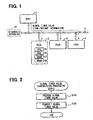
- FIG. 1 shows an onboard network of a first embodiment to which a failure-diagnosis information collection system is applied.
- the onboard network of the first embodiment includes multiple or four electronic control units (ECUs) 1 to 4 interconnected over a communication line 11 in a vehicle.
- ECUs electronice control units
- Each of the ECUs 1 to 4 includes a known microcomputer that can include a central processing unit (CPU) 15, a read only memory (ROM) 16, a static RAM (SRAM) 17, and a normal-RAM (NRAM) 18, though the components of the ECU 2 alone are shown in FIG. 1 .
- Programs to be executed by the CPU 15 are stored in the ROM 16.
- the SRAM 17 is a standby RAM to which even when feed of operating power to the ECU in which the SRAM is incorporated is discontinued, power originating from an onboard battery is always fed.
- the NRAM 18 is a normal RAM that has power feed thereto ceased when feed of operating power to the ECU is discontinued.
- the ECU 1 is an ECU that controls feed of operating power to the other ECUs 2 to 4 according to whether an ignition switch is turned on or off.
- the ECU 2 and ECU 3 are ECUs that cooperate with each other in controlling an engine in the vehicle in a manner similar to the above described first and second ECUs.
- the ECU 4 is an ECU that controls a transmission.
- a diagnosis apparatus 13 that diagnoses a failure of a vehicle can be outside the vehicle and can be connected on the communication line 11.
- the ECU 1 regularly transmits a global timer value, originating from a clock, to the other ECUs 2 to 4.
- the global timer value is stored in the ECUs 2 to 4 and updated therein.
- the global timer value represents time-instant information.
- a time that has elapsed since the ECU 1 is started is indicated in units of 1 ms.
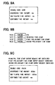
- global timer value transmission processing as shown, for example, in FIG. 2 is executed at regular intervals.
- a global timer value which can be the present value of the global timer, is produced at S110 and transmitted to the other ECUs 2 to 4.
- the produced global timer value is transmitted to the ECUs 2 to 4 over the communication line 11.
- each of the ECUs 2 to 4 executes global timer value reception processing as shown, for example, in FIG. 3 .
- the global timer value reception processing it is decided whether the global timer value sent from the ECU 1 has been received at S150. If the global timer value has not been received, the global timer value reception processing is terminated. If the global timer value has been received, the received global timer value is stored in, for example, the NRAM 18 at 5160 in order to update the data in the NRAM 18. Thereafter, the global timer value reception processing is terminated. Owing to the processing, the ECUs 2 to 4 share the same global timer value sent from the ECU 1.
- the NRAM 18 included in each of the ECUs 2 to 4 has a storage area in which a principal time stamp, a first preliminary time stamp, a second preliminary time stamp, and a first preliminary set history flag are stored in relation to one detected abnormality associated with the ECU or each of multiple detected abnormalities associated with the ECU.
- the time stamp and set history flag information are stored in relation to the contents of each abnormality.
- the principal time stamp is time-instant information associated with a time at which occurrence of an abnormality is confirmed.
- the first preliminary time stamp is time-instant information associated with a time at which a decision is made for the first time that the abnormality has occurred.
- the second preliminary time stamp is time-instant information associated with an intermediate time point between the instant when a decision is made for the first time that the abnormality has occurred and the instant when the occurrence of the abnormality is confirmed.
- the first preliminary set history flag signifies that a value is set or specified in the first preliminary time stamp.
- time stamp initialization processing described, for example, in connection with FIG. 4 is executed.
- the time stamp initialization processing is processing to be executed for each detected abnormality item associated with the ECU, in order to initialize the principal time stamp, first preliminary time stamp, second preliminary time stamp, and first preliminary set history flag which relate to the abnormality of the item.
- the first preliminary time stamp and second preliminary time stamp are first cleared or reset to 0s at S210.
- the principal time stamp is cleared.
- the first preliminary set history flag is reset. Thereafter, the time stamp initialization processing is terminated.
- the first preliminary set history flag is turned on through the processing described in FIG. 5 .
- abnormality detection processing as shown, for example, in FIG. 5 , is executed at regular intervals for each detected abnormality item.
- the processing proceeds to S310.
- a decision is made regarding whether an abnormality recognizing condition for the detected abnormality under which a decision should be made that the abnormality has occurred has been established. For example, assuming that the detected abnormality is a sensor abnormality, the abnormality recognizing condition is a condition that the output value of the sensor falls within an abnormal domain as shown for example in FIG. 6 .
- the processing proceeds to S315. It is decided whether the first preliminary flag is reset. When the first preliminary flag is reset, it means that a decision is made for the first time at S310 that the abnormality has occurred, resulting in the establishment of an abnormality recognition time. If a decision is made that the first preliminary flag is reset, the processing proceeds to S320, and the first preliminary flag is set. At S325, the first preliminary set history flag relevant to the detected abnormality is set. At S330, the global timer value acquired from the ECU 1 is specified in the first preliminary time stamp relevant to the detected abnormality. Thereafter, the processing proceeds to S335.
- a decision is made at S315 that the first preliminary flag is not reset but, rather, is set the processing proceeds to S335. If a decision is previously made at S310 that the abnormality has occurred, S320 to S330 are skipped. At S335, an abnormality counter that measures a time during which a decision, which is continuously made at S310 to decide that the abnormality has occurred, starts to count up. At S340, a normality counter is cleared.
- the normality counter is a counter that measures a time at S390 during which a condition of normality is continuously recognized. The normality counter and abnormality counter are cleared when the ECU is started.
- the time from the abnormality recognition time to the abnormality confirmation time shall hereinafter be called an abnormality recognition time. If a decision is made that the time has not elapsed, the processing proceeds to S365.
- the processing proceeds to S350.
- a decision is made regarding whether a second preliminary flag is reset. When the second preliminary flag is reset, it means that half of the abnormality recognition time since the abnormality recognition time has just elapsed. If a decision is made that the second preliminary flag is reset, the processing proceeds to S355, and the second preliminary flag is set.
- the global timer value acquired from the ECU 1 is specified in the second preliminary time stamp relevant to the detected abnormality. Thereafter, the processing proceeds to S365.
- a warning light can inform an occupant in the vehicle of the occurrence of an abnormality.
- the DTC can be stored in the SRAM 17 or in a rewritable ROM (not shown) such as a flash memory or an EEPROM incorporated in the ECU.
- the normality recognizing condition is a condition that the output value of the sensor falls within a normal domain as shown, for example, in FIG. 6 .
- the processing proceeds to S395, and the normality counter is allowed to count up.
- the abnormality counter is cleared.
- a decision is made based on the value of the normality counter whether a normality recognition time has elapsed since a decision was made at S390 for the first time that the normality recognizing condition is established. If a decision is made that the normality recognition time has not elapsed, then the processing proceeds to S425. Moreover, if a decision is made at 5405 that the normality recognition time has elapsed, the processing proceeds to S410. After normal-time processing is completed, the processing proceeds to S425. In the normal-time processing, for example, the warning light is disabled.
- the first preliminary flag and second preliminary flag are cleared. Thereafter, the abnormality detection processing is terminated. If a decision is made at S390 that the normality recognizing condition has not been established, the processing proceeds to S415.
- the normality counter is cleared.
- the abnormality counter is cleared. Thereafter, the processing proceeds to S425.
- the global timer value obtained from when a state changes from the abnormality recognizing condition not being established to the abnormality recognizing condition being established is stored.
- the abnormality recognition time is stored as the first preliminary time stamp at S330.
- the global timer value is stored as the second preliminary time stamp at S360.
- the global timer value obtained at the abnormality confirmation time when a DTC is stored is stored as the principal time stamp at S370.
- Abnormality detection processing to be executed for detected sensor abnormality will be described. For example, as shown in FIG. 6 , when the global timer value is 400, if the abnormality recognizing condition is established for the first time because the sensor output falls within the abnormal domain, the value of 400 is stored as the first preliminary time stamp.
- the sensor output then returns to the normal domain, and the abnormality recognizing condition can no longer be established. Thereafter, when the global timer value is 1200, if the abnormality recognizing condition is established again, the value of 1200 is stored as the first preliminary time stamp in order to update the previous first preliminary time stamp. Namely, the value of the first preliminary time stamp of 400 is overwritten with 1200.
- the abnormality recognition time is a time interval of 1000 ms during which the global timer value increases by 1000.
- the value of 1700 is stored as the second preliminary time stamp.
- the sensor abnormality is confirmed.
- the value of 2200 is stored as the principal time stamp, and a DTC representing the sensor abnormality is stored.
- the time instant at which an abnormal state has occurred can be learned based on the value of the first preliminary time stamp.
- the time instant at which the half of the abnormality recognition time has elapsed can be learned based on the value of the second preliminary time stamp.
- the abnormality confirmation time instant at which the abnormality recognition time has elapsed and a DTC is stored can be learned based on the principal time stamp.
- the abnormality recognizing condition can change such that the condition is no longer established. Thereafter, the abnormality recognizing condition is continuously established and half of the abnormality recognition time has elapsed.
- the global timer value at that time is stored as the second preliminary time stamp in order to update the previous second preliminary time stamp. Namely, the value of the second preliminary time stamp is overwritten with the latest value.
- the abnormality recognition time and normality recognition time vary depending on abnormality detection processing, such as on a detected abnormality.
- DTC output request response processing as shown, for example, in FIG. 7 is executed in response to a DTC output request and is transmitted from the diagnosis apparatus 13 connected on the communication line 11. It should be noted that when an attempt is made for reading a DTC from each of the ECUs 2 to 4, the diagnosis apparatus 13 transmits a DTC output request to each of the ECUs 2 to 4.
- the diagnosis apparatus 13 transmits a DTC output request to each of the ECUs 2 to 4.
- whether any of the principal time stamp, first preliminary time stamp, and second preliminary time stamp is read together with the DTC can be designated. If reading of any of the time stamps is designated, a DTC output request containing an output request for the designated time stamp is transmitted to each of the ECUs 2 to 4.
- DTC output request response processing to be executed in each of the ECUs 2 to 4, first, whether any DTC is stored in the SRAM 17 or rewritable ROM is decided at S510. If a decision is made that no DTC is stored, the processing proceeds to 5520. Information signifying that no DTC is stored is transmitted to the diagnosis apparatus 13. Thereafter, the DTC output request response processing is terminated.
- Occurrence Time Instant refers to an abnormality occurrence time instant
- a Half Elapse Time Instant refers to a time instant at which the duration of an abnormal state has reached the half of the abnormality recognition time
- Confirmed Time Instant refers to an abnormality confirmation time instant.
- DTC/time stamp output processing as shown, for example, in FIG. 8 is executed. Thereafter, the DTC output request response processing is terminated.
- the DTC/time stamp output processing as shown, for example, in FIG. 8 is the process of transmitting a stored DTC together with time stamps associated with the DTC, or more particularly, time stamps relevant to the abnormality represented by the DTC to the diagnosis apparatus 13, and is executed for each of DTCs stored.
- transmission data areas TR[0] to TR[3], which store data to be transmitted to the diagnosis apparatus 13, are cleared at S610.
- the stored DTC is written in the transmission data area TR[0].
- S630 whether a principal time stamp output request is contained in the DTC output request sent from the diagnosis apparatus 13 is decided at S630. If the principal time stamp output request is not contained in the DTC output request, the processing proceeds to S650. If the principal time stamp output request is contained in the DTC output request, the processing proceeds to S640.
- S640 the principal time stamp associated with the DTC written in the transmission data area TR[0] at S620 is written in the transmission data area TR[1].
- a second preliminary time stamp output request is contained in the DTC output request sent from the diagnosis apparatus 13 is decided. If the second preliminary time stamp output request is not contained in the DTC output request, the processing proceeds to S690. If the second preliminary time stamp output request is contained in the DTC output request, the processing proceeds to S680. At S680, the second preliminary time stamp associated with the DTC written in the transmission data area TR[0] at S620 is written in the transmission data area TR[3]. At S690, the data items written in the transmission data areas TR[0] to TR[3] are transmitted to the diagnosis apparatus 13. Thereafter, the DTC/time stamp output processing is terminated.
- the operation exerted by the DTC/time stamp output processing includes portions as will be described. For example, assume that a value of 0x0120 is stored as a DTC in the SRAM 17 or rewritable ROM, and values of 0x0320, 0x0708, and 0x0AF0 are stored in the NRAM 18 as the first preliminary time stamp, second preliminary time stamp, and principal time stamp respectively associated with the DTC. It should be noted that the alphanumeric strings beginning with 0x are hexadecimal numerals.
- the data items shown in FIG. 9B are then transmitted from the ECU 2 to the diagnosis apparatus 13.
- the diagnosis apparatus 13 displays the contents of display like those shown in FIG. 9C on the display screen thereof. Specifically, P0120 that is a display form of 0x0120 is displayed as a trouble code, 800 ms inferred from the value of the first preliminary time stamp is displayed as an occurrence time instant, and 1800 ms inferred from the value of the second preliminary time stamp is displayed as a half elapse time instant. As a confirmed time instant, - ms is displayed, signifying that no data is found.
- the diagnosis apparatus 13 When reading of the principal time stamp is designated at the diagnosis apparatus 13, if the principal time stamp output request is contained in the DTC output request sent from the diagnosis apparatus 13, the value of the principal time stamp, that is, 0x0AF0 is transmitted from the ECU 2 to the diagnosis apparatus 13. 2800 ms, which is inferred from the value of the principal time stamp, is displayed as the confirmed time instant on the display screen of the diagnosis apparatus 13.
- the contents of display like those shown in FIG. 9C are simultaneously displayed on the display screen of the diagnosis apparatus 13 in association with each of the DTCs or displayed thereon while being continuously switched to others.
- the diagnosis apparatus 13 may be designed to also display from which of the ECTs a DTC and time stamps have been sent.
- around-the-clock monitoring output request response processing as shown, for example, in FIG. 10 , is executed in response to an around-the-clock monitoring output request that is equivalent to an output request and is transmitted from the diagnosis apparatus 13.
- the diagnosis apparatus 13 When the diagnosis apparatus 13 is operated in order to monitor the first preliminary time stamp stored in each of the ECUs 2 to 4, the diagnosis apparatus 13 transmits an around-the-clock monitoring output request to each of the ECUs 2 to 4.
- whether the second preliminary time stamp is also monitored can be designated. If monitoring of the second preliminary time stamp is designated, the around-the-clock monitoring output request containing a second preliminary time stamp output request is transmitted to each of the ECUs 2 to 4.
- the diagnosis apparatus 13 transmits a monitoring cease request to each of the ECUs 2 to 4.
- the diagnosis apparatus 13 displays on the display screen thereof the contents of display like those shown in FIG. 12A .
- Indication refers to an indication of an abnormality. In this case, none is displayed as an indication.
- - ms signifying that no data is found is displayed as each of an occurrence time instant and a half elapse time instant.
- step 710 If a decision is made at S710 that the first preliminary set history flag is set, the processing proceeds to S730 since the set flag means that at least the first preliminary time stamp is stored in relation to any abnormality.
- preliminary time stamp output processing as shown, for example, in FIG. 11 is executed at regular intervals until a monitoring cease request is received from the diagnosis apparatus 13. When the monitoring cease request is received from the diagnosis apparatus 13, processing at S730 is suspended, and the around-the-clock monitoring output request response processing is terminated.
- the preliminary time stamp output processing as shown, for example, in FIG. 11 is the process of regularly transmitting the first preliminary time stamp and second preliminary time stamp stored in the NRAM 18, to the diagnosis apparatus 13, and is executed for each abnormality item relevant to which the first preliminary time stamp is stored.
- around-the-clock monitoring transmission data areas TRM[0] to TRM[2] in which data to be transmitted to the diagnosis apparatus 13 for around-the-clock monitoring is stored are cleared.
- the first preliminary time stamp that is an object of transmission is written in the around-the-clock monitoring transmission data area TRM[0].
- a second preliminary time stamp output request is contained in the around-the-clock monitoring output request sent from the diagnosis apparatus 13 is decided at S830. If the second preliminary time stamp output request is not contained, the processing proceeds to S850. If the second preliminary time stamp output request is contained, the processing proceeds to S840. Whether the second preliminary time stamp relevant to the same abnormality as the first preliminary time stamp written in the around-the-clock monitoring transmission data area TRM[0] at S820 is stored in the NRAM 18 is decided at S840. If the second preliminary time stamp is stored, the second preliminary time stamp is written in the around-the-clock monitoring transmission data area TRM[1]. Thereafter, the processing proceeds to S850.
- information signifying what DTC associated with the first preliminary time stamp is written in the around-the-clock monitoring transmission data area TRM[0] at S820.
- the DTC is written in the around-the-clock monitoring transmission data area TRM[2].
- the data items written in the around-the-clock monitoring transmission data areas TRM[0] to TRM[2] are transmitted to the diagnosis apparatus 13.
- a wait state is sustained for a certain time. Thereafter, the processing returns to 5805.
- the data items shown in FIG. 12B are then transmitted from the ECU 2 to the diagnosis apparatus 13, which displays the data items on the display screen as shown, for example, in FIG. 12C .
- Indication of P0120 Abnormality signifying that an indication of an abnormality represented by a DTC of P0120 that is a display form of 0x0120 is found is displayed as an indication. 1200 ms inferred from the value of the first preliminary time stamp is displayed as an occurrence time instant of the abnormality represented by P0120. 1700 ms inferred from the value of the second preliminary time stamp is displayed as a half elapse time instant for the abnormality represented by P0120.
- first preliminary time stamps relevant to multiple abnormality items are stored in one or more of the ECUs 2 to 4, the contents of display like those shown in FIG. 12C are simultaneously displayed on the display screen of the diagnosis apparatus 13 in association with each of the abnormality items or displayed thereon while being sequentially switched to others.
- the diagnosis apparatus 13 may be designed to also display from which of the ECUs each time stamp is sent.
- a DTC representing the abnormality and the principal time stamp are stored.
- the first preliminary time stamp is also stored at the abnormality recognition time at which a decision is made for the first time that the abnormality has occurred.
- the second preliminary time stamp is also stored at the time at which the half of the abnormality recognition time has elapsed since the abnormality recognition time.
- diagnosis apparatus 13 When the diagnosis apparatus 13 is connected on the communication line 11, if the diagnosis apparatus 13 is manipulated so that the diagnosis apparatus 13 will transmit a DTC output request, which contains a principal time stamp output request, a first preliminary time stamp output request, and a second preliminary time stamp output request, to each of the ECUs 2 to 4, each of the ECUs 2 to 4 transmits together with a DTC stored therein the first preliminary time stamp, second preliminary time stamp, and principal time stamp, which are associated with the DTC, to the diagnosis apparatus 13.
- the DTCs and time stamps read from the ECUs 2 to 4 to the diagnosis apparatus 13 are displayed on the display screen of the diagnosis apparatus 13.
- the time instant at which a decision is made for the first time that the abnormality represented by the DTC has occurred that is, an abnormality occurrence time instant independent of the abnormality recognition time can be learned.
- an abnormality that is a major factor having triggered the other abnormalities can be readily identified using the first preliminary time stamps. Therefore, when a repair is performed at a dealer of a vehicle or a maintenance shop, unnecessary replacement of a normal part derived from erroneous decision made on a faulty component can be prevented, and the faulty component can be efficiently repaired.
- a temporal transition signifying when an abnormality represented by the DTC is recognized for the first time and when the abnormality is confirmed can be learned.
- the second preliminary time stamp read together with the DTC is referenced, a temporal transition among three time points signifying when an abnormality represented by the DTC is recognized for the first time, when the half of the abnormality recognition time has elapsed, that is, when the half elapse time instant has come, and when the abnormality is confirmed can be readily learned. Consequently, when multiple DTCs are read from the ECUs 2 to 4, an abnormality that is a major factor having triggered the other abnormalities can be more accurately identified by comparing the temporal transitions relevant to the abnormalities represented by the respective DTCs with one another.
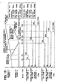
- 800, 1800, and 2800 are stored as a first preliminary time stamp a, a second preliminary time stamp a, and a principal time stamp a relevant to the abnormality "a.”
- 1600, 2000 and 2400 are stored as a first preliminary time stamp "b", a second preliminary time stamp "b,” and a principal time stamp "b" relevant to the abnormality "b.”
- abnormality recognition time for the abnormality "a" of 2000 ms is longer than the abnormality recognition time for the abnormality "b” of 800 ms abnormality "b” is interpreted as having occurred earlier than the abnormality "a.”
- the abnormality "b” has occurred due to the occurrence of the abnormality "a”
- the DTC "b” representing the abnormality "b” and the principal time stamp are stored in the ECU 3 earlier than the DTC "a” representing the abnormality "a”
- the principal time stamp are stored in the ECU 2. Consequently, when only the DTCs and principal time stamps are taken into consideration, a real cause of a failure cannot be discovered.
- the first preliminary time stamps and second preliminary time stamps relevant to the abnormalities "a” and “b” are also stored in the ECUs, and can be read together with the DTC "a” and “b” by the diagnosis apparatus 13.
- the possibility that the abnormality "a” may have triggered the abnormality "b” can be readily inferred.
- the upper one presents the contents of display on the diagnosis apparatus 13 provided when the DCT and time stamps relevant to the abnormality "a" are read from the ECU 2 to the diagnosis apparatus 13.
- the lower one presents the contents of display on the diagnosis apparatus 13 provided when the DTC and time stamps relevant to the abnormality "b” are read from the ECU 3 to the diagnosis apparatus 13.
- the abnormality "a” for example, an abnormality in a crank angle sensor is conceivable.
- the abnormality "b” a misfire abnormality is conceivable.
- each of the ECUs 2 to 4 in response to a DTC output request sent from the diagnosis apparatus 13, each of the ECUs 2 to 4 outputs time stamps, which are stored at that time, together with a DTC. Consequently, each of the ECUs 2 to 4 is allowed to output not only the principal time stamp but also the first and second preliminary time stamps only for an abnormality item for which an abnormality is confirmed.
- each of the ECUs 2 to 4 when an around-the-clock monitoring output request containing a second preliminary time stamp output request is transmitted from the diagnosis apparatus 13 to each of the ECUs 2 to 4, each of the ECUs 2 to 4 outputs the latest first and second preliminary time stamps to the diagnosis apparatus at regular intervals.
- the latest first and second preliminary time stamps are displayed on the display screen of the diagnosis apparatus 13.
- an around-the-clock monitoring output request devoid of the second preliminary time stamp output request is transmitted from the diagnosis apparatus 13 to each of the ECUs 2 to 4
- each of the ECUs 2 to 4 outputs only the latest first preliminary time stamp to the diagnosis apparatus 13 at regular intervals.
- the latest first preliminary time stamps are then displayed on the display screen of the diagnosis apparatus 13.
- the first or second preliminary time stamp is outputted from each of the ECUs 2 to 4 to the diagnosis apparatus 13, if the contents of display as shown, for example, in FIG. 13C , are displayed on the display screen of the diagnosis apparatus 13, the presence of an indication of an abnormality can be recognized.
- the abnormality detection processing as shown, for example, in FIG. 5 is equivalent to an abnormality detection means, and S310 in the processing is equivalent to a decision means.
- the first preliminary time stamp is equivalent to time-instant information associated with an abnormality recognition time.
- the second preliminary time stamp is equivalent to time-instant information associated with an intermediate time.
- the principal time stamp is equivalent to time-instant information associated with an abnormality confirmation time.
- a storage area which is defined in the NRAM 18 for each abnormality detection processing, that is, for each detected abnormality, and in which the first preliminary time stamp, second preliminary time stamp, and principal time stamp are stored refers to a storage area or a storage means in which the time-instant information associated with an abnormality recognition time, time-instant information associated with an intermediate time, time-instant information associated with an abnormality confirmation time are stored and which is a means included in the abnormality detection means.
- the DTC output request response processing as shown, for example, in FIG. 7 is equivalent to a response means
- the around-the-clock monitoring output request response processing as shown, for example, in FIG. 10 is equivalent to an output means.
- An onboard network in accordance with a second embodiment is different from that in accordance with a first embodiment as described herein below.
- multiple storage areas such as, for example, five storage areas in the present embodiment are defined in the NRAM 18 of each of the ECUs 2 to 4 in order to store the first and second preliminary time stamps for each abnormality item in each of the storage areas.
- Five first preliminary stamps and five second preliminary stamps beginning with the latest preliminary stamps are stored in the respective storage areas.
- the first preliminary time stamps may be referred to as the first preliminary time stamps Prel[0] to Pre1[4] or the first preliminary time stamps Pre1[k].
- k is an arrangement index and denotes an index value of from 0 to 4.
- the second preliminary time stamps may be referred to as the second preliminary time stamps Pre2[0] to Pre2[4] or the second preliminary time stamps Pre2[j].
- j is an arrangement index and denotes an index value of from 0 to 4. It should be noted that the number of first preliminary time stamps to be stored and the number of second preliminary time stamps to be stored may be different.
- time stamp initialization processing as shown, for example, in FIG. 14 is executed instead of the time stamp initialization processing as shown, for example, in FIG. 4 .
- the first preliminary time stamps Prel[0] to Pre2[4] and second preliminary time stamps Pre2[0] to Pre2[4], which relate to an abnormality and which are subjected to the time stamp initialization processing are cleared at S213.
- the arrangement indices k and j of the time stamps are cleared to 0s at S215. Thereafter, S220 and S230 identical to those in FIG. 4 are performed.
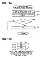
- abnormality detection processing as shown, for example, in FIG. 15 is executed instead of the abnormality detection processing as shown, for example, in FIG. 5 , and is different in that first preliminary time stamp storage processing as shown, for example, in FIG. 16A , is executed at S333 instead of S330 and in that second preliminary time stamp storage processing as shown, for example, in FIG. 17A , is executed at S363 instead of S360.
- a current global timer value acquired from the ECU 1 at an abnormality recognition time is specified in the first preliminary time stamp Pre1[k] relevant to a detected abnormality at S910.
- k denotes a value designated at that time.
- the k value is incremented by 1.
- the global timer value obtained at that time is specified in each of the first preliminary time stamps in ascending order from the first preliminary time stamp Pre1[0] to the first preliminary time stamp Pre1[4].
- the global timer value is specified in the first preliminary timer stamp Pre1[0] again.
- the multiple storage areas in the NRAM 18 in which the first preliminary time stamps are stored are so-called rolling data areas.
- a current global timer value acquired from the ECU 1, that is, a global timer value obtained when the half of the abnormality recognition time has elapsed is specified in the second preliminary time stamp Pre2[j] relevant to a detected abnormality.
- j denotes a value designated at that time.
- the j value is incremented by 1.
- the global timer value obtained at that time is specified in each of the second preliminary time stamps Pre2[0] to Pre2[4] in ascending order from the second preliminary time stamp Pre2[0] to the second preliminary time stamp Pre2[4].
- the global timer value is specified in the second preliminary time stamp Pre2[4] again.
- the multiple storage areas in the NRAM 19 in which the second preliminary time stamps are stored are so-called rolling data areas.
- the abnormality recognizing condition for an abnormality whose abnormality recognition time is set to 800 ms
- the values of 400, 600, 1100, and 1600 respectively are stored as the first preliminary time stamps Pre1[0] to Pre1[3] respectively.
- the abnormality recognizing condition is held established, when half of the abnormality recognition time, or 400 ms, has elapsed since the time point at which the global timer value is 1100, the global timer value at that time, or 1500, is stored as the second preliminary time stamp Pre2[0].
- the abnormality recognizing condition is held established, when 400 ms has elapsed since the time point at which the global timer value is 1600, the global timer value at that time, that is, 2000 is stored as the second preliminary time stamp Pre2[1].
- up to five first preliminary time stamps and up to five second preliminary time stamps beginning with the latest ones are stored in relation to each abnormality.
- the abnormality recognizing condition is continuously established since the time point at which the global timer value is 1600.
- the global timer value is 2400
- 2400 is stored as the principal time stamp and a DTC is stored.
- DTC/time stamp output processing as shown, for example, in FIG. 19 is executed instead of the DTC/time stamp output processing as shown, for example, in FIG. 8 .
- the DTC/time stamp output processing of FIG. 19 is different from the DTC/time stamp output processing of FIG. 8 in that S615, S665, S685, and S695 are performed instead of S610, S660, S680, and S690 respectively.
- the transmission data areas TR[0] to TR[11], in which data items to be transmitted to the diagnosis apparatus 13 are stored, are cleared. Namely, in the second embodiment, twelve data items can be stored in the 0th to eleventh transmission data areas.
- the first preliminary time stamps Pre1[0] to Pre1[4] associated with a DTC written in the transmission data area TR[0] at S620 are written in the transmission data areas TR[2] to TR[6].
- the second preliminary time stamps Pre2[0] to Pre2[4] associated with the DTC written in the transmission data area TR[0] at S620 are written in the transmission data areas TR[7] to TR[11].
- the data items written in the transmission data areas TR[0] to TR[11] are transmitted to the diagnosis apparatus 13.
- DTC/time stamp output processing in accordance with the second embodiment will be described as follows.
- 0x0120 is stored as a DTC in the SRAM 17 or rewritable ROM
- 0x0190, 0x0258, 0x044C, 0x0640, and 0x0000 are stored as the first preliminary time stamps Pre1[0] to Pre1[4] associated with the DTC in the NRAM 18.
- 0x0960 is stored in the NRAM 18 as the principal time stamp associated with the DTC.
- the data items shown in FIG. 20A are then transmitted from the ECU 2 to the diagnosis apparatus 13 and displayed.
- the items are displayed in a manner, for example, as shown in FIG. 20B .
- P0120 a display form of 0x0120
- the values of the first preliminary time stamps Pre1[0] to Pre1[3] that are decimal numerals are displayed as time instants 1 to 4, and "- ms" signifying that no data is found is displayed as a time instant 5. It should be noted that "- ms" is displayed as a half elapsed time instant, and the value of the principal time stamp, a decimal numeral, is displayed as a confirmed time instant.
- the second preliminary time stamps Pre2[0] to Pre2[4] associated with the DTC of 0x0120 are transmitted from the ECU 2 to the diagnosis apparatus 13. Items of Half Elapsed Time Instant 1 to Half Elapse Time Instant 4 are displayed on the display screen of the diagnosis apparatus 13, and the values of the second preliminary time stamps Pre2[0] to Pre2[4] are displayed for the respective items.
- the contents of display are simultaneously displayed on the display screen of the diagnosis apparatus 13 in association with each other, in a manner similar to those shown in FIG. 20B , or displayed thereon while being sequentially switched to others.
- the diagnosis apparatus 13 may be designed to also display from which of the ECUs a DTC and time stamps are sent.
- preliminary time stamp output processing as shown, for example, in FIG. 21 is executed instead of the preliminary time stamp output processing as shown, for example, in FIG. 11 .
- the preliminary time stamp output processing shown, for example, in FIG. 21 and FIG. 11 is different in that S815, S825, S845, S855, and S865 are performed instead of S810, S820, S840, S850, and S860 respectively.
- S815 the around-the-clock monitoring transmission data areas TRM[0] to TRM[10] in which around-the-clock monitoring transmission data items to be sent to the diagnosis apparatus 13 are stored are cleared.
- eleven data items can be stored in the 0th to tenth around-the-clock monitoring transmission data areas TRM.
- the first preliminary time stamps [0] to [4] that are objects of transmission are written in the around-the-clock monitoring transmission data areas TRM[0] to TRM[4] respectively.
- the second preliminary time stamps [0] to [4] relevant to the same abnormality as the first preliminary time stamps [k] written in the around-the-clock monitoring transmission data areas TRM[0] to TRM[4] at S825 are written in the around-the-clock monitoring transmission data areas TRM[5] to TRM[9] respectively.
- information signifying what is a DTC associated with the first preliminary time stamps [k] written in the around-the-clock monitoring transmission data areas TRM[0] to TRM[4] at S825, or the DTC in the present embodiment is written in the around-the-clock monitoring transmission data area TRM[10].
- the data items written in the around-the-clock monitoring transmission data areas TRM[0] to TRM[10] are transmitted to the diagnosis apparatus 13.
- the operation exerted by the preliminary time stamp output processing in accordance with a second embodiment will be described as follows.
- an around-the-clock monitoring output request devoid of a second preliminary time stamp output request is transmitted from the diagnosis apparatus 13 to each of the ECUs 2 to 4.
- 0x0190, 0x0258, 0x044C, 0x0640, and 0x0000 is stored as the first preliminary time stamps [0] to [4] relating to an abnormality represented by a DTC of 0x0120, in the NRAM 18.
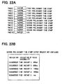
- data items are, as shown in FIG. 22A , written in the around-the-clock monitoring transmission data areas TRM[0] to TRM[10] through the preliminary time stamp output processing.
- an indication of P0120 abnormality signifies that an abnormality represented by a DTC of P0120 is a displayed form of 0x0120.
- occurrence time instants 1 to 5 relevant to the abnormality represented by P0120 as the occurrence time instants 1 to 4, the values of the first preliminary time stamps Pre1[0] to Pre1[3] that are decimal numerals are displayed.
- the values of the second preliminary time stamps Pre2[0] to Pre2[4] associated with the DTC of 0x0120 are transmitted from the ECU 2 to the diagnosis apparatus 13 at regular intervals.
- the items of Half Elapse Time Instant 1 to Half Elapse Time Instant 4 are displayed on the display screen of the diagnosis apparatus 13.
- the values of the second preliminary time stamps Pre2[0] to Pre2[4] are also displayed for the respective items.
- first preliminary time stamps for multiple abnormality items are stored in one or more of the ECUs 2 to 4, the contents of display like those shown in FIG. 22B are simultaneously displayed on the display screen of the diagnosis apparatus 13 in association with each of the abnormality items or displayed thereon while being sequentially switched to others.
- the diagnosis apparatus 13 may be designed to also display from which of the ECUs time stamps are sent. Even in the second embodiment, the preliminary time stamp output processing is repeated at regular intervals.
- the first preliminary time stamps and second preliminary time stamps stored in the ECUs 2 to 4 are updated, the updated time stamps are transmitted to the diagnosis apparatus 13. Time instants represented by the updated time stamps are displayed on the display screen of the diagnosis apparatus 13.
- first preliminary time stamps relevant to any abnormality are read from any of the ECUs 2 to 4 to the diagnosis apparatus 13 in response to a DTC output request sent from the diagnosis apparatus 13 to each of the ECUs 2 to 4, it can be learned whether the hunting phenomenon between abnormality recognition and normality recognition has occurred before the abnormality is confirmed.
- the time instant at which the hunting phenomenon has occurred and the frequency of the hunting can be learned based on the values of the first preliminary time stamps. Consequently, evidence leading to confirmation of an abnormality can be discriminated.
- the abnormality detection processing as shown, for example, in FIG. 15 is equivalent to the abnormality detection means, and S310 in the processing is equivalent to the decision means.
- Storage areas in the NRAM 18 which are defined for each abnormality detection processing or for each detected abnormality and in which multiple first preliminary time stamps and multiple second preliminary time stamps are stored refer to the storage means.
- the first preliminary time stamp, second preliminary time stamp, principal time stamp, and first preliminary set history flag may be stored in the SRAM 17.
- the time stamp initialization processing as shown, for example, in FIG. 4 or FIG. 14 is executed only immediately after an onboard battery is connected to a vehicle. Consequently, the time stamps and first preliminary set history flag can be continuously preserved regardless of whether the ignition switch is turned on or off. In other words, even if feed of operating power to the ECUs 2 to 4 is discontinued during a period from the instant when the abnormality recognizing condition is established to the instant when an abnormality is confirmed, the time stamps and first preliminary set history flag can be preserved. The occurrence time instant of an abnormality or an indication of an abnormality can be discriminated over a period during which the ignition switch remains off.
- One ECU may perform the processing shown, for example, in FIG. 3 and other processing, and may be configured to detect multiple abnormalities of different items. In such a case, the ECU need not always receive a global timer value from an other ECU, but may store the value of an internal clock as a time stamp value.
Description
- The present invention relates to failure diagnosis in a vehicle such as an automobile and, more specifically to collecting information about abnormalities.
- An electronic control unit (ECU) mounted in a vehicle can continuously execute self-diagnosis and, when a failure or an abnormality is detected, abnormality information such as a so-called diagnostic trouble code (DTC) representing the contents of the failure, and the year, month, day, and time instant or time-instant information can be stored in a storage means as described, for example, in
JP-A-7-181112 - In failure diagnosis processing in such an ECU, decision processing associated with deciding whether an abnormality has occurred is regularly executed. The occurrence of an abnormality is confirmed for the first time when an abnormality confirmation time is reached during decision processing. Waiting until an abnormality confirmation time before confirming the occurrence of an abnormality is intended to prevent erroneous detection. When the abnormality is confirmed, abnormality information is then stored.
- It should be noted that many modern vehicles have adopted a form of an onboard control network having multiple ECUs interconnected over a communication line, along with the capability for great diversity and complexity in the contents of the control afforded by such a network.
- In the onboard network, the multiple ECUs control respective objects while transferring and exchanging control information. When triggered for example by an abnormality in a certain region, abnormalities whose contents are different from each other may be detected in multiple ECUs at the same time.
- For example, when a pulsating crank angle sensor signal is inputted to an first ECU of two ECUs that cooperate with each other in controlling an engine, the first ECU transmits engine speed information, which is detected based on the crank angle sensor signal, to the second ECU whereupon the second ECU uses the engine speed information to execute processing. In a case where imperfect contact occurs on signal line extending from the crank angle sensor to the first ECU, an abnormality in the crank angle sensor will be registered if the crank angle sensor signal loses a pulse. Moreover, the engine speed information sent from the first ECU to the second ECU can undergo a larger fluctuation than normal due to the lost pulse. Based on the fluctuation, the second ECU decides that an imperfect ignition condition exists and thus detects a misfire abnormality.
- Even within one ECU, abnormalities whose contents are different from each other may be detected at the same time upon being triggered with an abnormality in a certain region. For example, an ECU that executes control processing using signal sent from a sensor while feeding power from a built-in power circuit to the sensor can detect multiple abnormalities triggered by an abnormality. Assuming that an output abnormality occurs in the power circuit for the sensor, a sensor power abnormality is detected through processing of monitoring an output of the power circuit. Moreover, a sensor abnormality is also detected through processing of monitoring a sensor signal since the power abnormality will prevent a normal sensor output.
- According to the related art, when occurrence of an abnormality is confirmed, time-instant information is stored together with abnormality information. If multiple abnormalities are detected in multiple ECUs or one ECU, the sequence in which individual abnormality information associated with the respective abnormalities are confirmed and stored can be learned by reading the abnormality information and the time-instant information.
- However, an abnormality confirmation time varies depending on the detection processing of each abnormality. If different abnormalities are detected upon being triggered by an abnormality in a certain region, one abnormality may be confirmed earlier than an other abnormality based on detection processing even though the other abnormality actually occurred earlier. That is, an erroneous ordering of an abnormality detection sequence may occur.
- In the related art, since time-instant information associated with when the time of occurrence of an abnormality is confirmed is stored, the phenomenon of erroneous ordering cannot be detected. Further, because of the erroneous ordering, it is not readily possibly to find an abnormality that has triggered detection of multiple abnormalities.
- For example, in the case of the two ECUs, assuming that a time when a decision regarding a crank angle sensor abnormality is confirmed in the first ECU is set after a time when a decision regarding a misfire abnormality is confirmed in the second ECU, even though the abnormality in the crank angle sensor has triggered the misfire abnormality, the misfire abnormality information may be stored in the second ECU earlier than the information associated with the crank angle sensor abnormality is stored in the first ECU through various differences in the detection processing. Consequently, the time-instant information stored together with the abnormality information demonstrates that the misfire abnormality has occurred earlier than the abnormality in the crank angle sensor. In such a case, the real cause of an abnormality or failure cannot be discovered.
- Document
US 5 696 676 A describes a control unit of a self-diagnosis apparatus for a vehicle, which includes a CPU and a non-volatile RAM, wherein the CPU has a function of detecting abnormalities occurring in vehicle-mounted devices and of inputting diagnostic data for the vehicle-mounted devices necessary for the analysis of detected abnormalities. In the case of an abnormality occurring in a particular vehicle-mounted device during two consecutive trips, the abnormality is judged to be a final abnormality, whereas an abnormality of the particular vehicle-mounted device detected during the first trip was judged to be only a temporary abnormality. - Document
US 2006/089767 A1 describes a method for diagnosis of a vehicle, which includes monitoring a first plurality of distributed sensor signals input to a first control unit, monitoring a second plurality of distributed sensor signals input to a second control unit, determining a first diagnostic trouble code (first DTC) at a first instant of time, determining a second DTC at a second instant of time, storing a first data set in a first storage medium and storing the second DTC in the first data set. The second instant of time is within a predetermined time of the first instant of time. The first data set corresponds to the first instant in time, and the stored first data set is transferred to a remote fault-diagnostic module at a later instant of time. The first data set includes the first DTC, a predetermined first group of sensor signals associated with either the first or second control unit, and the second DTC. - Accordingly, the present invention is intended to provide a failure-diagnosis information collection system that facilitates accurate failure diagnosis in a vehicle.
- The object is solved by the features of
independent claim 1. The dependent claims are directed to preferred embodiments of the invention. - In the failure-diagnosis information collection system, each of the abnormality recognition means stores time-instant information associated with an abnormality recognition time at which a state change occurs from a state in which the decision means decides that no abnormality has occurred to a state in which the decision means decides that an abnormality has occurred. In other words, the abnormality recognition means stores a time at which an abnormality is recognized for the first time as time-instant information in an abnormality unconfirmed stage.
- According to the failure-diagnosis information collection system, information stored by each of the abnormality recognition means is read. If abnormality information is found in the information, an abnormality item of an abnormality that is confirmed can be learned. Based on time-instant information associated with an abnormality confirmation time stored together with the abnormality information, a time instant at which a decision is made for the first time that the abnormality has occurred, that is, an occurrence-of-abnormality time instant can be learned. Consequently, when multiple abnormalities are detected, an abnormality that has triggered the other abnormalities can be easily identified. Such identification is a major factor in properly diagnosing a failure. For example, when a repair is performed at a dealership or maintenance shop, erroneous replacement of a non-defective part based on an improper diagnosis resulting from the inability to determine the cause of an abnormality can be prevented. The faulty component can be identified accurately and efficiently repaired and the abnormalities associated with vehicle can be fully repaired with one visit.
- According to the failure-diagnosis information collection system of
claim 2, the amount of information to be used to make a decision on an abnormality occurrence sequence advantageously increases. Specifically, information stored by each of the abnormality recognition means can be read. If multiple elements of abnormality information are stored, a temporal transition signifying when the corresponding abnormality is recognized for the first time and when the abnormality is confirmed can be learned based on the time-instant information associated with the abnormality recognition time and the time-instant information associated with the abnormality confirmation time. When the temporal transitions of the respective abnormalities are compared with one another, an abnormality that represents a major factor in triggering the other abnormalities can be more accurately identified. - According to
claim 3, if a detected abnormality event associated with any of the abnormality recognition means is repeatedly recognized by the decision means, but is no longer recognized when an abnormality confirmation time elapses, that is, if a hunting phenomenon occurs between abnormality recognition and normality recognition, the multiple time-instant information associated with abnormality recognition times are stored in the storage areas in the abnormality detection means. When the multiple time-instant information stored by any of the abnormality detection means is read, the frequency of the hunting can be learned and evidence leading to confirmation of an abnormality can be discriminated. - A constitution as defined in
claim 4 is advantageous in that resources can be saved by eliminating separate storage areas in which time-instant information associated with abnormal recognition beginning times. - The present invention is advantageous because of an increase in the amount of information to be used to decide an abnormality occurrence sequence. Specifically, when information stored by each of the abnormality recognition means are read, if multiple elements of abnormality information are found stored, the time-instant information associated with an abnormality recognition time and the time-instant information associated with an intermediate time reached can be used to learn a temporal transition from when an abnormality is recognized for the first time and when the intermediate time is reached. When the temporal transitions of all abnormalities are compared with one another, an abnormality that is a major factor having triggered the other abnormalities can be more accurately identified.
- A temporal transition among three time points signifying when an abnormality represented by abnormality information is recognized for the first time, when the time during which the abnormality is recognized has reached the intermediate time, and when the abnormality is confirmed can be readily learned. An abnormality of a major factor having triggered the other abnormalities can be more accurately identified.
- It should be noted that the intermediate time may be set to any value. The intermediate time should be set to a time that is a certain fraction of the abnormality confirmation time, that is, a time calculated by multiplying the abnormality confirmation time by a constant which is larger than 0 and falls below 1. When the intermediate time is thus determined, the time-instant information associated with an abnormality recognition time and the time-instant information associated with an intermediate time can be used to calculate a time instant at which the abnormality information is stored even in a constitution in which time-instant information associated with an abnormality confirmation time is not stored, as long as some abnormality information is stored. Assuming that the temporal transitions among three time points which relate to multiple abnormalities are compared with one another, the intermediate time should preferably be a half of the abnormality confirmation time because such a time division is intuitive and can be readily grasped.
- According to
claim 6, if the decision means repeatedly decides during a time equal to or longer than an intermediate time that a detected abnormality associated with any of the abnormality detection means has occurred, but the abnormality is no longer recognized after the abnormality confirmation time elapses, that is, if a hunting phenomenon occurs, multiple time-instant information associated with intermediate times are stored in the storage areas in the abnormality detection means. Consequently, when information stored by any of the abnormality detection means is read, if multiple time-instant information associated with intermediate times are found stored, the fact that the hunting phenomenon has occurred and the frequency of the hunting can be learned. Evidence of an abnormality that will highly possibly be confirmed can be discriminated. - The constitution of
claim 7 is advantageous in that storage areas in which time-instant information associated with intermediate times are stored, that is, resources can be saved. - It should further be noted that as a technique of reading information stored by the abnormality recognition means, techniques described below are conceivable.
- An exemplary abnormality recognition means includes as a component thereof a storage means in which information is stored. A recording medium serving as the storage means could be dismounted from an electronic control unit in which the failure-diagnosis information collection system is installed, and information could be read from the recording medium. However, such a technique requires work of physically dismounting the storage medium. The recording medium serving as the storage means may be included in each abnormality recognition means or may be shared by multiple abnormality recognition means. When a request signal for requesting any information is outputted from an external apparatus to the failure-diagnosis information collection system, a response means included in the failure-diagnosis information collection system outputs information associated with the request signal to the external apparatus. The information can include one of information stored by each of abnormality recognition means. In such a scenario, information to be read must be designated individually.
- When an information request signal is outputted from the external apparatus to the failure-diagnosis information collection system, the response means included in the failure-diagnosis information collection system outputs all information stored by each of the abnormality recognition means to the external apparatus. However, in such a scenario, time-instant information in an abnormality unconfirmed stage, that is, time information associated with an abnormality recognition time or time information associated with an intermediate time is outputted even for an abnormality item for which no abnormality is confirmed resulting in potentially wasteful analysis.
- Consequently, in a failure-diagnosis information collection system in accordance with still other embodiments, a response means is included as further described below.
- Specifically, in response to an abnormality information request issued from an external apparatus, the response means outputs together with abnormality information stored by the abnormality recognition means, time-instant information to the external apparatus. It should be noted that the time-instant information to be outputted by the response means is at least time-instant information associated with an abnormality recognition time, an abnormality confirmation time, or an intermediate time is outputted. Time-instant information associated with an abnormality recognition time, an abnormality confirmation time, or an intermediate time is outputted together with abnormality information only for an abnormality item for which an abnormality is confirmed. Consequently, if multiple abnormalities are recognized and multiple abnormality information stored, information needed to identify the abnormality that is a major factor in triggering multiple abnormalities is outputted. Information traffic to an external apparatus can be suppressed to the minimum extent necessary.
- In a failure-diagnosis information collection system in accordance with still other embodiments, an output means is included as further described below.
- Specifically, in response to an output request issued from an external apparatus, the output means regularly outputs time-instant information in an abnormality unconfirmed stage stored by the abnormality recognition means, to the external apparatus. It should be noted that the time-instant information in the abnormality unconfirmed stage to be outputted by the output means is at least time-instant information associated with an abnormality recognition time and can also include an intermediate time.
- In a failure-diagnosis information collection system in accordance with still other embodiments, time-instant information in an abnormality unconfirmed stage, that is, time-instant information associated with one or both of an abnormality recognition time or an intermediate time are regularly fetched into an external apparatus and can be continuously monitored. Even for an abnormality which has not been confirmed, evidence of an abnormality that is likely to be confirmed later can be discriminated. More particularly, when time-instant information associated with an abnormality recognition time or time-instant information associated with an intermediate time is outputted, an indication of an abnormality is discriminated. Moreover, occurrence of a hunting phenomenon between abnormality recognition and normality recognition, and the frequency of the hunting can be learned based on an interval between the time instants.
- It should be noted that if the failure-diagnosis information collection system is adapted to one electronic control unit, the failure-diagnosis information collection system should be installed in the one electronic control unit. If the failure-diagnosis information collection system is adapted to multiple electronic control units constituting an onboard network, the failure-diagnosis information collection system should be constituted as follows.
- Specifically, one or more abnormality recognition means can be included in each of multiple electronic control units that are mounted in a vehicle and communicate with one another. A response means is included in each of the electronic control units. In response to an abnormality information request, the response means outputs time-instant information stored by the abnormality recognition means included in the electronic control unit, to an external apparatus together with abnormality information stored by the abnormality detection means. An output means is included in each of the electronic control units. In response to an output request, the output means regularly outputs time-instant information in an abnormality unconfirmed stage, which is stored by the abnormality recognition means included in each electronic control unit, to the external apparatus.
- As mentioned above, each of the abnormality recognition means includes as a component thereof a storage means in which information is stored. As the storage means, for example, a standby random access memory (RAM) that may be referred to as a backup RAM, is a RAM to which power is continuously fed is conceivable. Assuming that the standby RAM is adopted as the storage means, even when an ignition switch in a vehicle is turned off and the operating power to the ECU in which the failure-diagnosis information collection system is installed is discontinued, time-instant information in an abnormality unconfirmed stage can continue to be stored. Even if the feed of the operating power is discontinued during a period from the instant when an abnormality is recognized for the first time to the instant when the abnormality is confirmed, an abnormality occurrence time instant or evidence leading to confirmation of an abnormality can be discriminated.
- Moreover, in order to save a resource of a standby RAM, a normal RAM may be adopted as the storage means in the abnormality recognition means, or more particularly, a storage means in which time-instant information in an abnormality unconfirmed stage is stored.
- Other objects, features and characteristics of the present invention will be appreciated and become apparent to those of ordinary skill in the art and all of which form a part of the present application. In the drawings:
-
FIG. 1 is a diagram illustrating an onboard network to which an embodiment is adapted; -
FIG. 2 is a flowchart illustrating global timer value transmission processing capable of being executed by an electronic control unit (ECU); -
FIG. 3 is a flowchart illustrating exemplary global timer value reception processing capable of being executed by ECUs in accordance with a first embodiment; -
FIG. 4 is a flowchart illustrating exemplary time stamp initialization processing capable of being executed by ECUs in accordance with a first embodiment; -
FIG. 5 is a flowchart illustrating exemplary abnormality detection processing capable of being executed by ECUs in accordance with a first embodiment; -
FIG. 6 is a timing chart expressing exemplary operation of the abnormality detection processing in accordance with a first embodiment; -
FIG. 7 is a flowchart illustrating exemplary diagnostic trouble code (DTC) output request response processing capable of being executed by the ECUs; -
FIG. 8 is a flowchart illustrating exemplary DTC/time stamp output processing capable of being executed in accordance with a first embodiment; -
FIG. 9A is a diagram illustrating exemplary time stamp output processing and the contents of display on a diagnosis apparatus in accordance with a first embodiment; -
FIG. 9B is a diagram illustrating exemplary DTC output processing and the contents of display on a diagnosis apparatus in accordance with a first embodiment; -
FIG. 9C is a diagram further illustrating exemplary time stamp output processing and the contents of display on a diagnosis apparatus in accordance with a first embodiment; -
FIG. 10 is a flowchart illustrating exemplary around-the-clock monitoring output request response processing capable of being executed by the ECUs; -
FIG. 11 is a flowchart illustrating exemplary preliminary time stamp output processing capable of being executed in accordance with a first embodiment; -
FIG. 12A is a diagram illustrating exemplary preliminary time stamp output processing and the contents of display on a diagnosis apparatus in accordance with a first embodiment; -
FIG. 12B is a diagram further illustrating exemplary preliminary time stamp output processing and the contents of display on the diagnosis apparatus in accordance with a first embodiment; -
FIG. 12C is a diagram further illustrating exemplary preliminary time stamp output processing and the contents of display on the diagnosis apparatus in accordance with a first embodiment; -
FIG. 13 is a timing diagram illustrating various advantageous timing relationships associated with a first embodiment; -
FIG. 14 is a flowchart illustrating exemplary time stamp initialization processing capable of being executed by the ECUs in accordance with a second embodiment; -
FIG. 15 is a flowchart illustrating abnormality detection processing capable of being executed by the ECUs in accordance with a second embodiment; -
FIG. 16A and FIG. 16B are diagrams illustrating exemplary first preliminary time stamp storage processing capable of being executed in accordance with a second embodiment; -
FIG. 17A and FIG. 17B are diagrams illustrating exemplary second preliminary time stamp storage processing capable of being executed in accordance with a second embodiment; -
FIG. 18 is a timing diagram illustrating exemplary timing relationships associated with abnormality detection processing in accordance with a second embodiment; -
FIG. 19 is a flowchart illustrating exemplary DTC/time stamp output processing capable of being executed in accordance with a second embodiment; -
FIG. 20A is a diagram illustrating exemplary DTC output processing and the contents of display on a diagnosis apparatus in accordance with a second embodiment; -
FIG. 20B is a diagram illustrating exemplary time stamp output processing and the contents of display on a diagnosis apparatus in accordance with a second embodiment; -
FIG. 21 is a flowchart illustrating exemplary preliminary time stamp output processing capable of being executed in accordance with a second embodiment; -
FIG. 22A is a diagram illustrating exemplary preliminary time stamp output processing and the contents of display on the diagnosis apparatus in accordance with a second embodiment; and -
FIG. 22B is a diagram further exemplary preliminary time stamp output processing and the contents of display on the diagnosis apparatus in accordance with a second embodiment. -
FIG. 1 shows an onboard network of a first embodiment to which a failure-diagnosis information collection system is applied. - As shown in
FIG. 1 , the onboard network of the first embodiment includes multiple or four electronic control units (ECUs) 1 to 4 interconnected over acommunication line 11 in a vehicle. - Each of the
ECUs 1 to 4 includes a known microcomputer that can include a central processing unit (CPU) 15, a read only memory (ROM) 16, a static RAM (SRAM) 17, and a normal-RAM (NRAM) 18, though the components of theECU 2 alone are shown inFIG. 1 . Programs to be executed by theCPU 15 are stored in theROM 16. It should be noted that theSRAM 17 is a standby RAM to which even when feed of operating power to the ECU in which the SRAM is incorporated is discontinued, power originating from an onboard battery is always fed. The NRAM 18 is a normal RAM that has power feed thereto ceased when feed of operating power to the ECU is discontinued. - For example, the
ECU 1 is an ECU that controls feed of operating power to theother ECUs 2 to 4 according to whether an ignition switch is turned on or off. TheECU 2 andECU 3 are ECUs that cooperate with each other in controlling an engine in the vehicle in a manner similar to the above described first and second ECUs. TheECU 4 is an ECU that controls a transmission. Moreover, adiagnosis apparatus 13 that diagnoses a failure of a vehicle can be outside the vehicle and can be connected on thecommunication line 11. - In the onboard network, the
ECU 1 regularly transmits a global timer value, originating from a clock, to theother ECUs 2 to 4. The global timer value is stored in theECUs 2 to 4 and updated therein. The global timer value represents time-instant information. In the present embodiment, a time that has elapsed since theECU 1 is started is indicated in units of 1 ms. - To be more specific, in the
ECU 1 having a global timer incorporated therein, global timer value transmission processing as shown, for example, inFIG. 2 is executed at regular intervals. When the global timer value transmission processing is initiated, a global timer value, which can be the present value of the global timer, is produced at S110 and transmitted to theother ECUs 2 to 4. At S120, the produced global timer value is transmitted to theECUs 2 to 4 over thecommunication line 11. - Every time information is received over the
communication line 11, each of theECUs 2 to 4 executes global timer value reception processing as shown, for example, inFIG. 3 . When the global timer value reception processing is initiated, it is decided whether the global timer value sent from theECU 1 has been received at S150. If the global timer value has not been received, the global timer value reception processing is terminated. If the global timer value has been received, the received global timer value is stored in, for example, the NRAM 18 at 5160 in order to update the data in the NRAM 18. Thereafter, the global timer value reception processing is terminated. Owing to the processing, theECUs 2 to 4 share the same global timer value sent from theECU 1. - Next, the other processing to be executed by each of the
ECUs 2 to 4 will be described. The processing shown, for example, inFIG. 2 andFIG. 3 , and the processing to be described below can actually be executed by theCPU 15 of the microcomputer included in each of the ECUs. - The NRAM 18 included in each of the
ECUs 2 to 4 has a storage area in which a principal time stamp, a first preliminary time stamp, a second preliminary time stamp, and a first preliminary set history flag are stored in relation to one detected abnormality associated with the ECU or each of multiple detected abnormalities associated with the ECU. In other in other words, the time stamp and set history flag information are stored in relation to the contents of each abnormality. The principal time stamp is time-instant information associated with a time at which occurrence of an abnormality is confirmed. The first preliminary time stamp is time-instant information associated with a time at which a decision is made for the first time that the abnormality has occurred. The second preliminary time stamp is time-instant information associated with an intermediate time point between the instant when a decision is made for the first time that the abnormality has occurred and the instant when the occurrence of the abnormality is confirmed. The first preliminary set history flag signifies that a value is set or specified in the first preliminary time stamp. - When an ignition switch of a vehicle is turned on, a battery voltage developed by an onboard battery, is fed as operating power to the
ECUs 2 to 4 based on the control operation of theECU 1. TheECUs 2 to 4 are then started. - When each of the
ECUs 2 to 4 is started, time stamp initialization processing described, for example, in connection withFIG. 4 is executed. The time stamp initialization processing is processing to be executed for each detected abnormality item associated with the ECU, in order to initialize the principal time stamp, first preliminary time stamp, second preliminary time stamp, and first preliminary set history flag which relate to the abnormality of the item. - Specifically, in the time stamp initialization processing, the first preliminary time stamp and second preliminary time stamp are first cleared or reset to 0s at S210. At the next S220, the principal time stamp is cleared. At S230, the first preliminary set history flag is reset. Thereafter, the time stamp initialization processing is terminated. When a value is specified in the first preliminary time stamp, the first preliminary set history flag is turned on through the processing described in
FIG. 5 . - Thereafter, in each of the
ECUs 2 to 4, abnormality detection processing as shown, for example, inFIG. 5 , is executed at regular intervals for each detected abnormality item. - In the abnormality detection processing, it is decided at S305 whether a detected abnormalities left unconfirmed. If the abnormality is left unconfirmed, that is, no decision is made confirming that the abnormality has occurred, the processing proceeds to S310. A decision is made regarding whether an abnormality recognizing condition for the detected abnormality under which a decision should be made that the abnormality has occurred has been established. For example, assuming that the detected abnormality is a sensor abnormality, the abnormality recognizing condition is a condition that the output value of the sensor falls within an abnormal domain as shown for example in
FIG. 6 . - If a decision is made at S310 that the abnormality recognizing condition is established, that is, if a decision is made that the detected abnormality has occurred, the processing proceeds to S315. It is decided whether the first preliminary flag is reset. When the first preliminary flag is reset, it means that a decision is made for the first time at S310 that the abnormality has occurred, resulting in the establishment of an abnormality recognition time. If a decision is made that the first preliminary flag is reset, the processing proceeds to S320, and the first preliminary flag is set. At S325, the first preliminary set history flag relevant to the detected abnormality is set. At S330, the global timer value acquired from the
ECU 1 is specified in the first preliminary time stamp relevant to the detected abnormality. Thereafter, the processing proceeds to S335. - If a decision is made at S315 that the first preliminary flag is not reset but, rather, is set, the processing proceeds to S335. If a decision is previously made at S310 that the abnormality has occurred, S320 to S330 are skipped. At S335, an abnormality counter that measures a time during which a decision, which is continuously made at S310 to decide that the abnormality has occurred, starts to count up. At S340, a normality counter is cleared. The normality counter is a counter that measures a time at S390 during which a condition of normality is continuously recognized. The normality counter and abnormality counter are cleared when the ECU is started.
- At S345, a decision is made based on the abnormality counter value regarding whether a half of a time from the abnormality recognition time to an abnormality confirmation time has elapsed. The time from the abnormality recognition time to the abnormality confirmation time shall hereinafter be called an abnormality recognition time. If a decision is made that the time has not elapsed, the processing proceeds to S365.
- At S365, a decision is made based on the abnormality counter value regarding whether the abnormality recognition time has elapsed since the abnormality recognition time. If a decision is made that the abnormality recognition time has not elapsed, the abnormality detection processing is terminated.
- If a decision is made at S345 that the half of the abnormality recognition time has elapsed, the processing proceeds to S350. A decision is made regarding whether a second preliminary flag is reset. When the second preliminary flag is reset, it means that half of the abnormality recognition time since the abnormality recognition time has just elapsed. If a decision is made that the second preliminary flag is reset, the processing proceeds to S355, and the second preliminary flag is set. At S360, the global timer value acquired from the
ECU 1 is specified in the second preliminary time stamp relevant to the detected abnormality. Thereafter, the processing proceeds to S365. - If a decision is made at S350 that the second preliminary flag is not reset but is set, the processing proceeds to S365. If a decision is previously made at 5345 that the half of the abnormality recognition time has elapsed, then S355 and S360 are skipped.
- If a decision is made at S365 that the abnormality recognition time has elapsed, the fact that the abnormality has occurred is confirmed. The processing then proceeds to 5370. The global timer value acquired from the
ECU 1 is specified in the principal time stamp relevant to the detected abnormality. At S375, abnormal-time processing is executed. After a diagnostic trouble code (DTC) that provides abnormality information signifying that the detected abnormality has occurred is stored at S380, the abnormality detection processing is terminated. - In abnormal-time processing, for example, a warning light can inform an occupant in the vehicle of the occurrence of an abnormality. Moreover, the DTC can be stored in the
SRAM 17 or in a rewritable ROM (not shown) such as a flash memory or an EEPROM incorporated in the ECU. - After the processing from S370 to S380 is completed, a decision is made at S305 that the detected abnormality should not be left unconfirmed, and is confirmed. If a decision is made at S305 that the abnormality is not left unconfirmed, or if a decision is made at S310 that the abnormality recognizing condition is not established, the processing proceeds to 5390.
- At S390, a decision is made regarding whether a normality recognizing condition in which a decision should be made that an abnormality is not found and the vehicle is normal is established for a detected abnormality. For example, assuming that the detected abnormality is a sensor abnormality, the normality recognizing condition is a condition that the output value of the sensor falls within a normal domain as shown, for example, in
FIG. 6 . - If a decision is made at S390 that the normality recognizing condition is established, the processing proceeds to S395, and the normality counter is allowed to count up. At S400, the abnormality counter is cleared. At S405, a decision is made based on the value of the normality counter whether a normality recognition time has elapsed since a decision was made at S390 for the first time that the normality recognizing condition is established. If a decision is made that the normality recognition time has not elapsed, then the processing proceeds to S425. Moreover, if a decision is made at 5405 that the normality recognition time has elapsed, the processing proceeds to S410. After normal-time processing is completed, the processing proceeds to S425. In the normal-time processing, for example, the warning light is disabled.
- At 5425, the first preliminary flag and second preliminary flag are cleared. Thereafter, the abnormality detection processing is terminated. If a decision is made at S390 that the normality recognizing condition has not been established, the processing proceeds to S415. The normality counter is cleared. At S420, the abnormality counter is cleared. Thereafter, the processing proceeds to S425.
- Specifically, in the abnormality detection processing, the global timer value obtained from when a state changes from the abnormality recognizing condition not being established to the abnormality recognizing condition being established, is stored. In other words, the abnormality recognition time is stored as the first preliminary time stamp at S330. When half of the abnormality recognition time has elapsed, that is, when the time during which a decision that the abnormality recognizing condition has been established is confirmed through continuous monitoring, and the time that has elapsed since the abnormality recognition time reaches the half of the abnormality recognition time, the global timer value is stored as the second preliminary time stamp at S360. When the time during which a decision, which is continuously confirmed, that the abnormality recognizing condition has been established and which has elapsed since the abnormality recognition time reaches the abnormality recognition time, the global timer value obtained at the abnormality confirmation time when a DTC is stored, is stored as the principal time stamp at S370.
- Abnormality detection processing to be executed for detected sensor abnormality will be described. For example, as shown in
FIG. 6 , when the global timer value is 400, if the abnormality recognizing condition is established for the first time because the sensor output falls within the abnormal domain, the value of 400 is stored as the first preliminary time stamp. - The sensor output then returns to the normal domain, and the abnormality recognizing condition can no longer be established. Thereafter, when the global timer value is 1200, if the abnormality recognizing condition is established again, the value of 1200 is stored as the first preliminary time stamp in order to update the previous first preliminary time stamp. Namely, the value of the first preliminary time stamp of 400 is overwritten with 1200.
- Assume that the abnormality recognition time is a time interval of 1000 ms during which the global timer value increases by 1000. When the global timer value becomes 1700 because the abnormality recognizing condition is continuously established, the value of 1700 is stored as the second preliminary time stamp. Thereafter, when the global timer value becomes 2200 because the abnormality recognizing condition is continuously established, the sensor abnormality is confirmed. The value of 2200 is stored as the principal time stamp, and a DTC representing the sensor abnormality is stored.
- Consequently, when the time stamps are read from the respective storage destinations, the time instant at which an abnormal state has occurred can be learned based on the value of the first preliminary time stamp. The time instant at which the half of the abnormality recognition time has elapsed can be learned based on the value of the second preliminary time stamp. The abnormality confirmation time instant at which the abnormality recognition time has elapsed and a DTC is stored can be learned based on the principal time stamp.
- It should be noted that in
FIG. 6 , during a period from when the global timer value is 1700 to when the global timer value is 2200, the abnormality recognizing condition can change such that the condition is no longer established. Thereafter, the abnormality recognizing condition is continuously established and half of the abnormality recognition time has elapsed. In such a case, the global timer value at that time is stored as the second preliminary time stamp in order to update the previous second preliminary time stamp. Namely, the value of the second preliminary time stamp is overwritten with the latest value. Moreover, the abnormality recognition time and normality recognition time vary depending on abnormality detection processing, such as on a detected abnormality. - In each of the
ECUs 2 to 4, DTC output request response processing as shown, for example, inFIG. 7 is executed in response to a DTC output request and is transmitted from thediagnosis apparatus 13 connected on thecommunication line 11. It should be noted that when an attempt is made for reading a DTC from each of theECUs 2 to 4, thediagnosis apparatus 13 transmits a DTC output request to each of theECUs 2 to 4. When the operation is performed, whether any of the principal time stamp, first preliminary time stamp, and second preliminary time stamp is read together with the DTC can be designated. If reading of any of the time stamps is designated, a DTC output request containing an output request for the designated time stamp is transmitted to each of theECUs 2 to 4. - In DTC output request response processing to be executed in each of the
ECUs 2 to 4, first, whether any DTC is stored in theSRAM 17 or rewritable ROM is decided at S510. If a decision is made that no DTC is stored, the processing proceeds to 5520. Information signifying that no DTC is stored is transmitted to thediagnosis apparatus 13. Thereafter, the DTC output request response processing is terminated. - When information signifying that no DTC is stored is transmitted from each of the
ECUs 2 to 4, the contents of display like those shown inFIG. 9A are displayed on the screen of a display device included in thediagnosis apparatus 13. The screen of the display device will thereinafter be referred to as the display screen. It should be noted that Occurrence Time Instant refers to an abnormality occurrence time instant, a Half Elapse Time Instant refers to a time instant at which the duration of an abnormal state has reached the half of the abnormality recognition time, and Confirmed Time Instant refers to an abnormality confirmation time instant. - If a decision is made at S510 that a DTC is stored, the processing proceeds to S530. DTC/time stamp output processing as shown, for example, in
FIG. 8 is executed. Thereafter, the DTC output request response processing is terminated. The DTC/time stamp output processing as shown, for example, inFIG. 8 , is the process of transmitting a stored DTC together with time stamps associated with the DTC, or more particularly, time stamps relevant to the abnormality represented by the DTC to thediagnosis apparatus 13, and is executed for each of DTCs stored. - When execution of the DTC/time stamp output processing is initiated, transmission data areas TR[0] to TR[3], which store data to be transmitted to the
diagnosis apparatus 13, are cleared at S610. At S620, the stored DTC is written in the transmission data area TR[0]. Thereafter, whether a principal time stamp output request is contained in the DTC output request sent from thediagnosis apparatus 13 is decided at S630. If the principal time stamp output request is not contained in the DTC output request, the processing proceeds to S650. If the principal time stamp output request is contained in the DTC output request, the processing proceeds to S640. At S640, the principal time stamp associated with the DTC written in the transmission data area TR[0] at S620 is written in the transmission data area TR[1]. - At S650, whether a first preliminary time stamp output request is contained in the DTC output request sent from the
diagnosis apparatus 13 is decided. If the first preliminary time stamp output request is not contained in the DTC output request, the processing proceeds to S670. If the first preliminary time stamp output request is contained in the DTC output request, the processing proceeds to 5660. At S660, the first preliminary time stamp associated with the DTC written in the transmission area TR[0] at S620 is written in the transmission data area TR[2]. - At S670, whether a second preliminary time stamp output request is contained in the DTC output request sent from the
diagnosis apparatus 13 is decided. If the second preliminary time stamp output request is not contained in the DTC output request, the processing proceeds to S690. If the second preliminary time stamp output request is contained in the DTC output request, the processing proceeds to S680. At S680, the second preliminary time stamp associated with the DTC written in the transmission data area TR[0] at S620 is written in the transmission data area TR[3]. At S690, the data items written in the transmission data areas TR[0] to TR[3] are transmitted to thediagnosis apparatus 13. Thereafter, the DTC/time stamp output processing is terminated. - The operation exerted by the DTC/time stamp output processing includes portions as will be described. For example, assume that a value of 0x0120 is stored as a DTC in the
SRAM 17 or rewritable ROM, and values of 0x0320, 0x0708, and 0x0AF0 are stored in the NRAM 18 as the first preliminary time stamp, second preliminary time stamp, and principal time stamp respectively associated with the DTC. It should be noted that the alphanumeric strings beginning with 0x are hexadecimal numerals. Assuming that the DTC output request containing the first preliminary time stamp output request and second preliminary time stamp output request is transmitted from thediagnosis apparatus 13 to each of theECUs 2 to 4, corresponding data items are written in the transmission data areas TR[0] to TR[3] in theECU 2 through the DTC/time stamp output processing as shown inFIG. 9B . It should be noted that the data in the transmission area TR[1] is cleared to 0x0000 since reading of the principal time stamp is not designated at thediagnosis apparatus 13. The principal time stamp output request is therefore not contained in the DTC output request sent from thediagnosis apparatus 13. - The data items shown in
FIG. 9B are then transmitted from theECU 2 to thediagnosis apparatus 13. Thediagnosis apparatus 13 displays the contents of display like those shown inFIG. 9C on the display screen thereof. Specifically, P0120 that is a display form of 0x0120 is displayed as a trouble code, 800 ms inferred from the value of the first preliminary time stamp is displayed as an occurrence time instant, and 1800 ms inferred from the value of the second preliminary time stamp is displayed as a half elapse time instant. As a confirmed time instant, - ms is displayed, signifying that no data is found. - When reading of the principal time stamp is designated at the
diagnosis apparatus 13, if the principal time stamp output request is contained in the DTC output request sent from thediagnosis apparatus 13, the value of the principal time stamp, that is, 0x0AF0 is transmitted from theECU 2 to thediagnosis apparatus 13. 2800 ms, which is inferred from the value of the principal time stamp, is displayed as the confirmed time instant on the display screen of thediagnosis apparatus 13. - If multiple DTCs are stored in one or more of the
ECUs 2 to 4, the contents of display like those shown inFIG. 9C are simultaneously displayed on the display screen of thediagnosis apparatus 13 in association with each of the DTCs or displayed thereon while being continuously switched to others. Moreover, thediagnosis apparatus 13 may be designed to also display from which of the ECTs a DTC and time stamps have been sent. - Thereafter, in each of the
ECUs 2 to 4, around-the-clock monitoring output request response processing as shown, for example, inFIG. 10 , is executed in response to an around-the-clock monitoring output request that is equivalent to an output request and is transmitted from thediagnosis apparatus 13. When thediagnosis apparatus 13 is operated in order to monitor the first preliminary time stamp stored in each of theECUs 2 to 4, thediagnosis apparatus 13 transmits an around-the-clock monitoring output request to each of theECUs 2 to 4. When the operation is performed, whether the second preliminary time stamp is also monitored can be designated. If monitoring of the second preliminary time stamp is designated, the around-the-clock monitoring output request containing a second preliminary time stamp output request is transmitted to each of theECUs 2 to 4. Moreover, when a specific monitoring cease operation is performed at thediagnosis apparatus 13, thediagnosis apparatus 13 transmits a monitoring cease request to each of theECUs 2 to 4. - As shown, for example, in
FIG. 10 , in the around-the-clock monitoring output request response processing in each of theECUs 2 to 4, whether the first preliminary set history flag relevant to any detected abnormality, that is, the first preliminary set history flag associated with any DTC is set is decided at S710. If a decision is made that the first preliminary set history flag is not set, the processing proceeds to S720. Information signifying that no preliminary time stamp is stored is transmitted to thediagnosis apparatus 13. Thereafter, the around-the-clock monitoring output request response processing is terminated. - When information signifying that no preliminary time stamp is stored is transmitted from each of the
ECUs 2 to 4, thediagnosis apparatus 13 displays on the display screen thereof the contents of display like those shown inFIG. 12A . It should be noted that Indication refers to an indication of an abnormality. In this case, none is displayed as an indication. Moreover, - ms signifying that no data is found is displayed as each of an occurrence time instant and a half elapse time instant. - If a decision is made at S710 that the first preliminary set history flag is set, the processing proceeds to S730 since the set flag means that at least the first preliminary time stamp is stored in relation to any abnormality. At S730, preliminary time stamp output processing as shown, for example, in
FIG. 11 is executed at regular intervals until a monitoring cease request is received from thediagnosis apparatus 13. When the monitoring cease request is received from thediagnosis apparatus 13, processing at S730 is suspended, and the around-the-clock monitoring output request response processing is terminated. - The preliminary time stamp output processing as shown, for example, in
FIG. 11 , is the process of regularly transmitting the first preliminary time stamp and second preliminary time stamp stored in the NRAM 18, to thediagnosis apparatus 13, and is executed for each abnormality item relevant to which the first preliminary time stamp is stored. - When execution of the preliminary time stamp output processing is initiated, whether a monitoring cease request has been received from the
diagnosis apparatus 13 is decided at S805. If a decision is made that the monitoring cease request has been received, the preliminary time stamp output processing is terminated, and S730 inFIG. 10 is suspended. If a decision is made that the monitoring cease request has not been received, the processing proceeds to S810. - At S810, around-the-clock monitoring transmission data areas TRM[0] to TRM[2] in which data to be transmitted to the
diagnosis apparatus 13 for around-the-clock monitoring is stored are cleared. At S820, the first preliminary time stamp that is an object of transmission is written in the around-the-clock monitoring transmission data area TRM[0]. - Thereafter, whether a second preliminary time stamp output request is contained in the around-the-clock monitoring output request sent from the
diagnosis apparatus 13 is decided at S830. If the second preliminary time stamp output request is not contained, the processing proceeds to S850. If the second preliminary time stamp output request is contained, the processing proceeds to S840. Whether the second preliminary time stamp relevant to the same abnormality as the first preliminary time stamp written in the around-the-clock monitoring transmission data area TRM[0] at S820 is stored in the NRAM 18 is decided at S840. If the second preliminary time stamp is stored, the second preliminary time stamp is written in the around-the-clock monitoring transmission data area TRM[1]. Thereafter, the processing proceeds to S850. - At S850, information signifying what DTC associated with the first preliminary time stamp is written in the around-the-clock monitoring transmission data area TRM[0] at S820. In the present embodiment, the DTC is written in the around-the-clock monitoring transmission data area TRM[2]. Thereafter, at S860, the data items written in the around-the-clock monitoring transmission data areas TRM[0] to TRM[2] are transmitted to the
diagnosis apparatus 13. At S870, a wait state is sustained for a certain time. Thereafter, the processing returns to 5805. - The operation of the preliminary time stamp output processing will now be described. For example, assume that an around-the-clock monitoring output request containing a second preliminary time stamp output request is transmitted from the
diagnosis apparatus 13 to each of theECUs 2 to 4. In theECU 2, 0x04B0 and 0x06A4 are stored as the first preliminary time stamp and second preliminary time stamp respectively relevant to an abnormality represented by a DTC that is 0x0120. In such a case, in theECU 2, data items are, as shown inFIG. 12B , written in the around-the-clock monitoring transmission data areas TRM[0] to TRM[2] through preliminary time stamp output processing. - The data items shown in
FIG. 12B are then transmitted from theECU 2 to thediagnosis apparatus 13, which displays the data items on the display screen as shown, for example, inFIG. 12C . Specifically, Indication of P0120 Abnormality signifying that an indication of an abnormality represented by a DTC of P0120 that is a display form of 0x0120 is found is displayed as an indication. 1200 ms inferred from the value of the first preliminary time stamp is displayed as an occurrence time instant of the abnormality represented by P0120. 1700 ms inferred from the value of the second preliminary time stamp is displayed as a half elapse time instant for the abnormality represented by P0120. It will be appreciated that since the preliminary time stamp output processing is repeated at regular intervals, when the first preliminary time stamp and second preliminary time stamp stored in each of theECUs 2 to 4 are updated, the latest time stamps are transmitted to thediagnosis apparatus 13. Consequently, the time instants inferred from the updated time stamps are displayed on the display screen of thediagnosis apparatus 13. - If first preliminary time stamps relevant to multiple abnormality items are stored in one or more of the
ECUs 2 to 4, the contents of display like those shown inFIG. 12C are simultaneously displayed on the display screen of thediagnosis apparatus 13 in association with each of the abnormality items or displayed thereon while being sequentially switched to others. Moreover, thediagnosis apparatus 13 may be designed to also display from which of the ECUs each time stamp is sent. - According to the foregoing onboard network, when the fact that any abnormality has occurred in each of the
ECUs 2 to 4 is confirmed, a DTC representing the abnormality and the principal time stamp are stored. Moreover, the first preliminary time stamp is also stored at the abnormality recognition time at which a decision is made for the first time that the abnormality has occurred. Moreover, the second preliminary time stamp is also stored at the time at which the half of the abnormality recognition time has elapsed since the abnormality recognition time. - When the
diagnosis apparatus 13 is connected on thecommunication line 11, if thediagnosis apparatus 13 is manipulated so that thediagnosis apparatus 13 will transmit a DTC output request, which contains a principal time stamp output request, a first preliminary time stamp output request, and a second preliminary time stamp output request, to each of theECUs 2 to 4, each of theECUs 2 to 4 transmits together with a DTC stored therein the first preliminary time stamp, second preliminary time stamp, and principal time stamp, which are associated with the DTC, to thediagnosis apparatus 13. The DTCs and time stamps read from theECUs 2 to 4 to thediagnosis apparatus 13 are displayed on the display screen of thediagnosis apparatus 13. - Based on the first preliminary time stamp among the first preliminary time stamp, second preliminary time stamp, and principal time stamp read together with the DTC from each of the
ECUs 2 to 4 to thediagnosis apparatus 13, the time instant at which a decision is made for the first time that the abnormality represented by the DTC has occurred, that is, an abnormality occurrence time instant independent of the abnormality recognition time can be learned. When multiple DTCs are read from theECUs 2 to 4, that is, when multiple abnormalities are detected in one or two or more of theECUs 2 to 4, an abnormality that is a major factor having triggered the other abnormalities can be readily identified using the first preliminary time stamps. Therefore, when a repair is performed at a dealer of a vehicle or a maintenance shop, unnecessary replacement of a normal part derived from erroneous decision made on a faulty component can be prevented, and the faulty component can be efficiently repaired. - Based on the first preliminary time stamp and principal time stamp read together with the DTC from each of the
ECUs 2 to 4, a temporal transition signifying when an abnormality represented by the DTC is recognized for the first time and when the abnormality is confirmed can be learned. Further, when the second preliminary time stamp read together with the DTC is referenced, a temporal transition among three time points signifying when an abnormality represented by the DTC is recognized for the first time, when the half of the abnormality recognition time has elapsed, that is, when the half elapse time instant has come, and when the abnormality is confirmed can be readily learned. Consequently, when multiple DTCs are read from theECUs 2 to 4, an abnormality that is a major factor having triggered the other abnormalities can be more accurately identified by comparing the temporal transitions relevant to the abnormalities represented by the respective DTCs with one another. - For example, as shown in
FIG. 13 , in theECU 2, when the global timer value is 800, a decision is made for the first time that an abnormality a has occurred. Thereafter, 2000 ms, which is the abnormality recognition time for a first abnormality, abnormality "a," elapses. When the global timer value becomes 2800, a DTC "a," which is a DTC representing the abnormality "a" is stored. Moreover, an abnormality "b" associated with theECU 3 is detected due to the occurrence of the abnormality "a." In theECU 3, when the global timer value is 1600, a decision is made for the first time that the abnormality "b" has occurred. Thereafter, 800 ms, which is the abnormality recognition time for the abnormality "b" elapses. When the global time value becomes 2400, a DTC "b," which is a DCT representing the abnormality "b" is stored. - In such a case, 800, 1800, and 2800 are stored as a first preliminary time stamp a, a second preliminary time stamp a, and a principal time stamp a relevant to the abnormality "a." In the
ECU - In the present example, since the abnormality recognition time for the abnormality "a" of 2000 ms is longer than the abnormality recognition time for the abnormality "b" of 800 ms abnormality "b" is interpreted as having occurred earlier than the abnormality "a." Specifically, although the abnormality "b" has occurred due to the occurrence of the abnormality "a," the DTC "b" representing the abnormality "b," and the principal time stamp are stored in the
ECU 3 earlier than the DTC "a" representing the abnormality "a," and the principal time stamp are stored in theECU 2. Consequently, when only the DTCs and principal time stamps are taken into consideration, a real cause of a failure cannot be discovered. - In contrast, according to the present embodiment, the first preliminary time stamps and second preliminary time stamps relevant to the abnormalities "a" and "b" are also stored in the ECUs, and can be read together with the DTC "a" and "b" by the
diagnosis apparatus 13. The fact that the abnormality "a" has occurred earlier than the abnormality "b" has can be learned based on the first and second preliminary time stamps relevant to the abnormalities "a" and "b." The possibility that the abnormality "a" may have triggered the abnormality "b" can be readily inferred. - Out of two square frames on the right side of
FIG. 13 , the upper one presents the contents of display on thediagnosis apparatus 13 provided when the DCT and time stamps relevant to the abnormality "a" are read from theECU 2 to thediagnosis apparatus 13. The lower one presents the contents of display on thediagnosis apparatus 13 provided when the DTC and time stamps relevant to the abnormality "b" are read from theECU 3 to thediagnosis apparatus 13. As an example of the abnormality "a," for example, an abnormality in a crank angle sensor is conceivable. As an example of the abnormality "b," a misfire abnormality is conceivable. - The same advantage is provided even when the abnormalities "a" and "b" shown in
FIG. 13 are abnormalities detected in one ECU. For example, an abnormality "a" in a sensor power supply or in a heater that activates an oxygen sensor is conceivable. An abnormality "b" in a sensor such as an oxygen sensor is conceivable. In the present embodiment, in response to a DTC output request sent from thediagnosis apparatus 13, each of theECUs 2 to 4 outputs time stamps, which are stored at that time, together with a DTC. Consequently, each of theECUs 2 to 4 is allowed to output not only the principal time stamp but also the first and second preliminary time stamps only for an abnormality item for which an abnormality is confirmed. Therefore, when multiple abnormalities are detected, or in other words, when multiple DTCs are stored, information is outputted that is necessary to identify the abnormality that is a major factor in triggering additional abnormalities. The traffic to thediagnosis apparatus 13 can be suppressed to the minimum necessary. - In the present embodiment, when an around-the-clock monitoring output request containing a second preliminary time stamp output request is transmitted from the
diagnosis apparatus 13 to each of theECUs 2 to 4, each of theECUs 2 to 4 outputs the latest first and second preliminary time stamps to the diagnosis apparatus at regular intervals. The latest first and second preliminary time stamps are displayed on the display screen of thediagnosis apparatus 13. When an around-the-clock monitoring output request devoid of the second preliminary time stamp output request is transmitted from thediagnosis apparatus 13 to each of theECUs 2 to 4, each of theECUs 2 to 4 outputs only the latest first preliminary time stamp to thediagnosis apparatus 13 at regular intervals. The latest first preliminary time stamps are then displayed on the display screen of thediagnosis apparatus 13. - Consequently, even for an unconfirmed abnormality, evidence that the abnormality will likely to be confirmed later can be discriminated. Specifically, when the first or second preliminary time stamp is outputted from each of the
ECUs 2 to 4 to thediagnosis apparatus 13, if the contents of display as shown, for example, inFIG. 13C , are displayed on the display screen of thediagnosis apparatus 13, the presence of an indication of an abnormality can be recognized. - In the first embodiment, the abnormality detection processing as shown, for example, in
FIG. 5 is equivalent to an abnormality detection means, and S310 in the processing is equivalent to a decision means. The first preliminary time stamp is equivalent to time-instant information associated with an abnormality recognition time. The second preliminary time stamp is equivalent to time-instant information associated with an intermediate time. The principal time stamp is equivalent to time-instant information associated with an abnormality confirmation time. Moreover, a storage area which is defined in the NRAM 18 for each abnormality detection processing, that is, for each detected abnormality, and in which the first preliminary time stamp, second preliminary time stamp, and principal time stamp are stored refers to a storage area or a storage means in which the time-instant information associated with an abnormality recognition time, time-instant information associated with an intermediate time, time-instant information associated with an abnormality confirmation time are stored and which is a means included in the abnormality detection means. The DTC output request response processing as shown, for example, inFIG. 7 is equivalent to a response means, and the around-the-clock monitoring output request response processing as shown, for example, inFIG. 10 is equivalent to an output means. - An onboard network in accordance with a second embodiment is different from that in accordance with a first embodiment as described herein below.
- Instead of one storage area, multiple storage areas such as, for example, five storage areas in the present embodiment are defined in the NRAM 18 of each of the
ECUs 2 to 4 in order to store the first and second preliminary time stamps for each abnormality item in each of the storage areas. Five first preliminary stamps and five second preliminary stamps beginning with the latest preliminary stamps are stored in the respective storage areas. - In order to discriminate five first preliminary time stamps for each abnormality item from one another, the first preliminary time stamps may be referred to as the first preliminary time stamps Prel[0] to Pre1[4] or the first preliminary time stamps Pre1[k]. Herein, k is an arrangement index and denotes an index value of from 0 to 4. Likewise, in order to discriminate five second preliminary time stamps for each abnormality item, the second preliminary time stamps may be referred to as the second preliminary time stamps Pre2[0] to Pre2[4] or the second preliminary time stamps Pre2[j]. Herein, j is an arrangement index and denotes an index value of from 0 to 4. It should be noted that the number of first preliminary time stamps to be stored and the number of second preliminary time stamps to be stored may be different.
- In each of the
ECUs 2 to 4, time stamp initialization processing as shown, for example, inFIG. 14 is executed instead of the time stamp initialization processing as shown, for example, inFIG. 4 . In the time stamp initialization processing ofFIG. 14 , the first preliminary time stamps Prel[0] to Pre2[4] and second preliminary time stamps Pre2[0] to Pre2[4], which relate to an abnormality and which are subjected to the time stamp initialization processing, are cleared at S213. The arrangement indices k and j of the time stamps are cleared to 0s at S215. Thereafter, S220 and S230 identical to those inFIG. 4 are performed. - In each of the
ECUs 2 to 4, abnormality detection processing as shown, for example, inFIG. 15 is executed instead of the abnormality detection processing as shown, for example, inFIG. 5 , and is different in that first preliminary time stamp storage processing as shown, for example, inFIG. 16A , is executed at S333 instead of S330 and in that second preliminary time stamp storage processing as shown, for example, inFIG. 17A , is executed at S363 instead of S360. - In the first preliminary time stamp storage processing as shown, for example, in
FIG. 16A , a current global timer value acquired from theECU 1 at an abnormality recognition time, is specified in the first preliminary time stamp Pre1[k] relevant to a detected abnormality at S910. Herein, k denotes a value designated at that time. At S920, the k value is incremented by 1. At S930, it is decided whether a condition where k≥5 exists. If the condition where k≥5 has not been established, the first preliminary time stamp storage processing is terminated. If k≥5 is established, the processing proceeds to S940, and the k value is reset to 0. Thereafter, the first preliminary time stamp storage processing is terminated. - As shown in
FIG. 16B , every time the first preliminary time stamp storage processing is executed at S333 inFIG. 15 , the global timer value obtained at that time is specified in each of the first preliminary time stamps in ascending order from the first preliminary time stamp Pre1[0] to the first preliminary time stamp Pre1[4]. After the global timer value is specified in the first preliminary time stamp Pre1[4], the global timer value is specified in the first preliminary timer stamp Pre1[0] again. Namely, the multiple storage areas in the NRAM 18 in which the first preliminary time stamps are stored are so-called rolling data areas. - In the second preliminary time stamp storage processing as shown, for example, in
FIG. 17A , at S950, a current global timer value acquired from theECU 1, that is, a global timer value obtained when the half of the abnormality recognition time has elapsed is specified in the second preliminary time stamp Pre2[j] relevant to a detected abnormality. Herein, j denotes a value designated at that time. At S960, the j value is incremented by 1. At S970, it is decided whether a condition where j≥5 exists. If the condition of j≥5 does not exist, the processing proceeds to S980, and the j value is reset to 0. Thereafter, the second preliminary time stamp storage processing is terminated. - As shown in
FIG. 17B , every time the second preliminary time stamp storage processing as shown, for example, inFIG. 15 is executed, the global timer value obtained at that time is specified in each of the second preliminary time stamps Pre2[0] to Pre2[4] in ascending order from the second preliminary time stamp Pre2[0] to the second preliminary time stamp Pre2[4]. After the global timer value is specified in the second preliminary time stamp Pre2[4], the global timer value is specified in the second preliminary time stamp Pre2[0] again. The multiple storage areas in the NRAM 19 in which the second preliminary time stamps are stored are so-called rolling data areas. - Owing to the differences between embodiments described above, for example, as shown in
FIG. 18 , assuming that the abnormality recognizing condition for an abnormality, whose abnormality recognition time is set to 800 ms, is established for the first time at the times indicated by the global timer values of 400, 600, 1100, and 1600 respectively, the values of 400, 600, 1100, and 1600 respectively are stored as the first preliminary time stamps Pre1[0] to Pre1[3] respectively. Moreover, while the abnormality recognizing condition is held established, when half of the abnormality recognition time, or 400 ms, has elapsed since the time point at which the global timer value is 1100, the global timer value at that time, or 1500, is stored as the second preliminary time stamp Pre2[0]. Likewise, while the abnormality recognizing condition is held established, when 400 ms has elapsed since the time point at which the global timer value is 1600, the global timer value at that time, that is, 2000 is stored as the second preliminary time stamp Pre2[1]. - As mentioned above, in the second embodiment, up to five first preliminary time stamps and up to five second preliminary time stamps beginning with the latest ones are stored in relation to each abnormality. In the example shown in
FIG. 18 , the abnormality recognizing condition is continuously established since the time point at which the global timer value is 1600. When the global timer value is 2400, 2400 is stored as the principal time stamp and a DTC is stored. - With regard to further differences from a first embodiment, in each of the
ECUs 2 to 4, in accordance with a second embodiment, at S530 inFIG. 7 , DTC/time stamp output processing as shown, for example, inFIG. 19 is executed instead of the DTC/time stamp output processing as shown, for example, inFIG. 8 , The DTC/time stamp output processing ofFIG. 19 is different from the DTC/time stamp output processing ofFIG. 8 in that S615, S665, S685, and S695 are performed instead of S610, S660, S680, and S690 respectively. - At S615, the transmission data areas TR[0] to TR[11], in which data items to be transmitted to the
diagnosis apparatus 13 are stored, are cleared. Namely, in the second embodiment, twelve data items can be stored in the 0th to eleventh transmission data areas. - At S665, the first preliminary time stamps Pre1[0] to Pre1[4] associated with a DTC written in the transmission data area TR[0] at S620 are written in the transmission data areas TR[2] to TR[6].
- At 5685, the second preliminary time stamps Pre2[0] to Pre2[4] associated with the DTC written in the transmission data area TR[0] at S620 are written in the transmission data areas TR[7] to TR[11].
- At 5695, the data items written in the transmission data areas TR[0] to TR[11] are transmitted to the
diagnosis apparatus 13. - The operation performed by the DTC/time stamp output processing in accordance with the second embodiment will be described as follows. For example, in the
ECU 2, assume that 0x0120 is stored as a DTC in theSRAM 17 or rewritable ROM, and that 0x0190, 0x0258, 0x044C, 0x0640, and 0x0000 are stored as the first preliminary time stamps Pre1[0] to Pre1[4] associated with the DTC in the NRAM 18. Moreover, 0x0960 is stored in the NRAM 18 as the principal time stamp associated with the DTC. - In the present case, assuming that a DTC output request containing a first preliminary time stamp output request and a principal time stamp output request is transmitted from the
diagnosis apparatus 13 to each of theECUs 2 to 4, data items are, as shown inFIG. 20A , written in the transmission data areas TR[0] to TR[11] in theECU 2 through the DTC/time stamp output processing. In the present example, since a global timer value is not specified in the first preliminary time stamp Pre1[4], data in the transmission data area TR[6] is 0x0000. Moreover, data items in the transmission data areas TR[7] to TR[11] are cleared to 0x0000 because reading of second preliminary time stamps has not been designated at thediagnosis apparatus 13. The DTC output request sent from thediagnosis apparatus 13 does not therefore contain a second preliminary time stamp output request. - The data items shown in
FIG. 20A are then transmitted from theECU 2 to thediagnosis apparatus 13 and displayed. The items are displayed in a manner, for example, as shown inFIG. 20B . Specifically, P0120, a display form of 0x0120, is displayed as a trouble code. The values of the first preliminary time stamps Pre1[0] to Pre1[3] that are decimal numerals are displayed astime instants 1 to 4, and "- ms" signifying that no data is found is displayed as atime instant 5. It should be noted that "- ms" is displayed as a half elapsed time instant, and the value of the principal time stamp, a decimal numeral, is displayed as a confirmed time instant. - Assuming that reading of second preliminary time stamps has been designated at the
diagnosis apparatus 13 and that a DTC output request sent from thediagnosis apparatus 13 contains a second preliminary time stamp output request, the second preliminary time stamps Pre2[0] to Pre2[4] associated with the DTC of 0x0120 are transmitted from theECU 2 to thediagnosis apparatus 13. Items of Half ElapsedTime Instant 1 to HalfElapse Time Instant 4 are displayed on the display screen of thediagnosis apparatus 13, and the values of the second preliminary time stamps Pre2[0] to Pre2[4] are displayed for the respective items. - When multiple DTCs are stored in one or more of the
ECUs 2 to 4, the contents of display are simultaneously displayed on the display screen of thediagnosis apparatus 13 in association with each other, in a manner similar to those shown inFIG. 20B , or displayed thereon while being sequentially switched to others. Thediagnosis apparatus 13 may be designed to also display from which of the ECUs a DTC and time stamps are sent. - In each of the
ECUs 2 to 4, at S730 inFIG. 10 , preliminary time stamp output processing as shown, for example, inFIG. 21 is executed instead of the preliminary time stamp output processing as shown, for example, inFIG. 11 . The preliminary time stamp output processing shown, for example, inFIG. 21 andFIG. 11 is different in that S815, S825, S845, S855, and S865 are performed instead of S810, S820, S840, S850, and S860 respectively. At S815, the around-the-clock monitoring transmission data areas TRM[0] to TRM[10] in which around-the-clock monitoring transmission data items to be sent to thediagnosis apparatus 13 are stored are cleared. Namely, in a second embodiment, eleven data items can be stored in the 0th to tenth around-the-clock monitoring transmission data areas TRM. At S825, the first preliminary time stamps [0] to [4] that are objects of transmission are written in the around-the-clock monitoring transmission data areas TRM[0] to TRM[4] respectively. At S845, the second preliminary time stamps [0] to [4] relevant to the same abnormality as the first preliminary time stamps [k] written in the around-the-clock monitoring transmission data areas TRM[0] to TRM[4] at S825 are written in the around-the-clock monitoring transmission data areas TRM[5] to TRM[9] respectively. At S855, information signifying what is a DTC associated with the first preliminary time stamps [k] written in the around-the-clock monitoring transmission data areas TRM[0] to TRM[4] at S825, or the DTC in the present embodiment is written in the around-the-clock monitoring transmission data area TRM[10]. At 5865, the data items written in the around-the-clock monitoring transmission data areas TRM[0] to TRM[10] are transmitted to thediagnosis apparatus 13. - The operation exerted by the preliminary time stamp output processing in accordance with a second embodiment will be described as follows. For example, assume that an around-the-clock monitoring output request devoid of a second preliminary time stamp output request is transmitted from the
diagnosis apparatus 13 to each of theECUs 2 to 4. In theECU 2, 0x0190, 0x0258, 0x044C, 0x0640, and 0x0000 is stored as the first preliminary time stamps [0] to [4] relating to an abnormality represented by a DTC of 0x0120, in the NRAM 18. In such a case, in theECU 2, data items are, as shown inFIG. 22A , written in the around-the-clock monitoring transmission data areas TRM[0] to TRM[10] through the preliminary time stamp output processing. - The data items shown in
FIG. 22A are then transmitted from theECU 2 to thediagnosis apparatus 13 and are displayed on the display screen, the contents of which are like those shown inFIG. 22B . Specifically, an indication of P0120 abnormality signifies that an abnormality represented by a DTC of P0120 is a displayed form of 0x0120. Amongoccurrence time instants 1 to 5 relevant to the abnormality represented by P0120, as theoccurrence time instants 1 to 4, the values of the first preliminary time stamps Pre1[0] to Pre1[3] that are decimal numerals are displayed. As theoccurrence time instant 5, since the value of the first preliminary time stamp Pre1[4] is 0x0000, a value of "- ms," which signifies that no data is found, is displayed. Moreover, "- ms" is displayed for a half elapse time instant relevant to the abnormality represented by P0120. - Assuming that monitoring of second preliminary time stamps is designated at the
diagnosis apparatus 13 and an around-the-clock monitoring output request sent from thediagnosis apparatus 13 contains a second preliminary time stamp output request, the values of the second preliminary time stamps Pre2[0] to Pre2[4] associated with the DTC of 0x0120 are transmitted from theECU 2 to thediagnosis apparatus 13 at regular intervals. The items of HalfElapse Time Instant 1 to HalfElapse Time Instant 4 are displayed on the display screen of thediagnosis apparatus 13. Moreover, the values of the second preliminary time stamps Pre2[0] to Pre2[4] are also displayed for the respective items. - When first preliminary time stamps for multiple abnormality items are stored in one or more of the
ECUs 2 to 4, the contents of display like those shown inFIG. 22B are simultaneously displayed on the display screen of thediagnosis apparatus 13 in association with each of the abnormality items or displayed thereon while being sequentially switched to others. Thediagnosis apparatus 13 may be designed to also display from which of the ECUs time stamps are sent. Even in the second embodiment, the preliminary time stamp output processing is repeated at regular intervals. When the first preliminary time stamps and second preliminary time stamps stored in theECUs 2 to 4 are updated, the updated time stamps are transmitted to thediagnosis apparatus 13. Time instants represented by the updated time stamps are displayed on the display screen of thediagnosis apparatus 13. - According to the onboard network in accordance with a second embodiment, additional advantages are provided as follows. When a repeated abnormality recognizing condition is established for a short period for any of the abnormalities that are objects of detection of the
respective ECUs 2 to 4, that is, when a hunting phenomenon occurs between abnormality recognition and normality recognition, multiple first preliminary time stamps relevant to the abnormality are stored. - When multiple first preliminary time stamps relevant to any abnormality are read from any of the
ECUs 2 to 4 to thediagnosis apparatus 13 in response to a DTC output request sent from thediagnosis apparatus 13 to each of theECUs 2 to 4, it can be learned whether the hunting phenomenon between abnormality recognition and normality recognition has occurred before the abnormality is confirmed. The time instant at which the hunting phenomenon has occurred and the frequency of the hunting can be learned based on the values of the first preliminary time stamps. Consequently, evidence leading to confirmation of an abnormality can be discriminated. - When multiple first preliminary time stamps relevant to any abnormality are read from any of the
ECUs 2 to 4 to thediagnosis apparatus 13 in response to an around-the-clock monitoring output request sent from thediagnosis apparatus 13 to each of theECUs 2 to 4, the occurrence of the hunting phenomenon between abnormality recognition and normality recognition in relation to the abnormality, the occurrence time instant of the hunting, and the frequency of the hunting can be learned. Evidence of an abnormality that may be confirmed later can be discriminated. - Likewise, when an event that an abnormality recognizing condition for any of abnormalities that are objects of detection of the
respective ECUs 2 to 4 is established for a short period of time longer than the half of the abnormality recognition time and shorter than the abnormality recognition time is repeated, that is, when a hunting phenomenon between abnormality recognition and normality recognition or a hunting phenomenon associated with abnormality confirmation occurs, multiple second preliminary time stamps relevant to the abnormality are stored. - Consequently, when multiple second preliminary time stamps relevant to any abnormality are read from any of the
ECUs 2 to 4 to thediagnosis apparatus 13 in response to an around-the-clock monitoring output request sent from thediagnosis apparatus 13 to each of theECUs 2 to 4, the occurrence time instant of the hunting phenomenon oriented to abnormality confirmation, and the frequency of the hunting can be learned based on the values of the second preliminary time stamps. Eventually, evidence of an abnormality that is highly possibly confirmed can be discriminated. - In the second embodiment, the abnormality detection processing as shown, for example, in
FIG. 15 is equivalent to the abnormality detection means, and S310 in the processing is equivalent to the decision means. Storage areas in the NRAM 18 which are defined for each abnormality detection processing or for each detected abnormality and in which multiple first preliminary time stamps and multiple second preliminary time stamps are stored refer to the storage means. - The invention is not limited to the embodiments described so far but can, needless to say, be implemented in various forms within the scope of the invention as claimed without departure therefrom.
- For example, in the above-described embodiments, the first preliminary time stamp, second preliminary time stamp, principal time stamp, and first preliminary set history flag may be stored in the
SRAM 17. In such a case, the time stamp initialization processing as shown, for example, inFIG. 4 orFIG. 14 is executed only immediately after an onboard battery is connected to a vehicle. Consequently, the time stamps and first preliminary set history flag can be continuously preserved regardless of whether the ignition switch is turned on or off. In other words, even if feed of operating power to theECUs 2 to 4 is discontinued during a period from the instant when the abnormality recognizing condition is established to the instant when an abnormality is confirmed, the time stamps and first preliminary set history flag can be preserved. The occurrence time instant of an abnormality or an indication of an abnormality can be discriminated over a period during which the ignition switch remains off. - One ECU may perform the processing shown, for example, in
FIG. 3 and other processing, and may be configured to detect multiple abnormalities of different items. In such a case, the ECU need not always receive a global timer value from an other ECU, but may store the value of an internal clock as a time stamp value.
Claims (11)
- A failure-diagnosis information collection system comprising:a plurality of vehicle abnormality recognition means for recognizing a plurality of abnormality items, the vehicle abnormality recognition means each including a decision means for deciding whether a recognized one of the plurality of abnormality items has actually occurred, and if a time during which the decision means continuously decides whether the abnormality has occurred (S310) reaches an abnormality confirmation time (S365), storing abnormality information signifying that the abnormality has occurred (S380), whereinthe abnormality confirmation time varies between the plurality of abnormality recognition means;characterized in thatthe plurality of vehicle abnormality recognition means each include a storing means (18) storing time-instant information associated with an abnormality recognition time at which the decision means changes from deciding that no abnormality has occurred to deciding that an abnormality has occurred, the time-instant information is stored as an abnormality unconfirmed decision;when a time during which the decision means included in a vehicle abnormality recognition means of the plurality of vehicle abnormality recognition means continuously decides whether an abnormality has occurred (S310) reaches an intermediate time (S345) that is shorter than the abnormality confirmation time, the storing means (18) included in the vehicle abnormality recognition means stores time-instant information associated with an intermediate time as time-instant information in an abnormality unconfirmed stage (S360).
- The failure-diagnosis information collection system according to claim 1,
wherein each storing means (18) stores time-instant information associated with a time at which the occurrence of an abnormality is confirmed (S370). - The failure-diagnosis information collection system according to claim 1,
wherein each storing means (18) includes N storage areas (Pre1), where N denotes an integer greater than or equal to 2, wherein the time-instant information associated with the abnormality recognition time and N time-instant information elements associated
with abnormality recognition times that begin with the latest time-instant information are stored in each of the N storage areas (Pre1) associated with the respective storage areas. - The failure-diagnosis information collection system according to claim 1,
wherein each of the plurality of means (18) included in the vehicle abnormality recognition means includes a storage area in which a latest time-instant information associated with an abnormality recognition time is stored. - The failure-diagnosis information collection system according to claim 1,
wherein the intermediate time is one half of the abnormality confirmation time. - The failure-diagnosis information collection system according to claim 1,
wherein each storing means (18) includes M storage areas (Pre2), where M denotes an integer equal to or larger than 2, each of the M storage areas (Pre2) storing the time-instant information associated with the intermediate time, and storing M time-instant information elements associated with intermediate times that begin with the latest time-instant information in the respective storage areas. - The failure-diagnosis information collection system according to claim 1,
wherein each storing means (18) includes one storage area in which time-instant information associated with an intermediate time is stored, and stores only the latest time-instant information associated with an intermediate time in the storage area. - The failure-diagnosis information collection system according to claim 1, further comprising a response means (S695) that outputs the time-instant information together with the abnormality information stored by the abnormality recognition means to an external apparatus in response to an abnormality information request (S630) sent from the external apparatus.
- The failure-diagnosis information collection system according to claim 8, further comprising an output means (S865) that regularly outputs time-instant information, stored by the abnormality recognition means, in an abnormality unconfirmed stage, the time-instant information being output to the external apparatus in response to an output request sent from the external apparatus (S830).
- The failure-diagnosis information collection system according to claim 8, wherein:one or more abnormality recognition means are installed in each of a plurality of electronic control units (2, 3, 4) that are mounted in the vehicle and communicate with one another; andthe response means (S695) is installed in each of the plurality of electronic control units (2, 3, 4) and outputs time-instant information together with abnormality information stored by the abnormality recognition means installed in the each of the plurality of electronic control units (2, 3, 4), the time-instant information being output to the external apparatus in response to the abnormality information request.
- The failure-diagnosis information collection system according to claim 9, wherein:one or more abnormality recognition means are installed in each of a plurality of electronic control units (2, 3, 4) mounted in the vehicle, the one or more abnormality recognition means communicating with one another;the response means (S695) is installed in each of the plurality of electronic control units (2, 3, 4), the response means outputting time-instant information together with abnormality information stored by the abnormality recognition means, the time instant information being output to the external apparatus in response to the output request; andthe output means (S865) is installed in each of the electronic control units (2, 3, 4), and regularly outputs time-instant information in an abnormality unconfirmed stage stored by the abnormality recognition means, the time instant information being output to the external apparatus in response to the output request.
Applications Claiming Priority (1)
| Application Number | Priority Date | Filing Date | Title |
|---|---|---|---|
| JP2007152767A JP4306765B2 (en) | 2007-06-08 | 2007-06-08 | Information collection device for fault diagnosis |
Publications (4)
| Publication Number | Publication Date |
|---|---|
| EP2000874A2 EP2000874A2 (en) | 2008-12-10 |
| EP2000874A3 EP2000874A3 (en) | 2010-09-29 |
| EP2000874B1 true EP2000874B1 (en) | 2012-07-11 |
| EP2000874B8 EP2000874B8 (en) | 2012-09-05 |
Family
ID=39745341
Family Applications (1)
| Application Number | Title | Priority Date | Filing Date |
|---|---|---|---|
| EP08010384A Expired - Fee Related EP2000874B8 (en) | 2007-06-08 | 2008-06-06 | Failure-diagnosis information collection system |
Country Status (3)
| Country | Link |
|---|---|
| US (1) | US8078355B2 (en) |
| EP (1) | EP2000874B8 (en) |
| JP (1) | JP4306765B2 (en) |
Families Citing this family (32)
| Publication number | Priority date | Publication date | Assignee | Title |
|---|---|---|---|---|
| JP4736828B2 (en) * | 2006-02-03 | 2011-07-27 | 株式会社デンソー | Electronic control unit |
| FR2920895B1 (en) * | 2007-09-06 | 2014-11-28 | Peugeot Citroen Automobiles Sa | METHOD FOR MANAGING FAILURES WITH MEMORIZATION OF SUCH FAILURES FOR A MOTOR VEHICLE |
| JP4458179B2 (en) * | 2008-03-27 | 2010-04-28 | トヨタ自動車株式会社 | Fault detection device, fault detection system, fault detection method |
| JP4623189B2 (en) * | 2008-09-26 | 2011-02-02 | 株式会社デンソー | Abnormality determination apparatus, abnormality determination program, and abnormality determination method |
| JP5208872B2 (en) * | 2009-07-15 | 2013-06-12 | 日立オートモティブシステムズ株式会社 | Memory diagnostic device for vehicle equipment control device |
| FR2949865B1 (en) * | 2009-09-09 | 2012-10-05 | Peugeot Citroen Automobiles Sa | SELF-DIAGNOSIS OF MECATRONIC COMPUTERS |
| JP5347997B2 (en) | 2010-02-04 | 2013-11-20 | 株式会社デンソー | Information collection device for fault diagnosis |
| JP5343920B2 (en) * | 2010-04-27 | 2013-11-13 | 株式会社デンソー | Failure sign detection device |
| JP5556824B2 (en) * | 2011-03-18 | 2014-07-23 | 株式会社デンソー | In-vehicle system, ECU, storage instruction transmission device, and storage request transmission device |
| JP5360148B2 (en) * | 2011-07-12 | 2013-12-04 | 株式会社デンソー | Electronic control unit |
| DE102011121441A1 (en) * | 2011-12-16 | 2013-06-20 | GM Global Technology Operations LLC (n. d. Gesetzen des Staates Delaware) | Method for operating a fault diagnosis system of a vehicle and vehicle |
| JP5556801B2 (en) * | 2011-12-19 | 2014-07-23 | 株式会社デンソー | On-vehicle electronic control device and diagnostic system |
| JP5439522B2 (en) * | 2012-02-22 | 2014-03-12 | 本田技研工業株式会社 | Vehicle data collection device and vehicle data collection method |
| EP2708963A1 (en) | 2012-09-12 | 2014-03-19 | Alstom Technology Ltd. | Devices and methods for diagnosis of industrial electronic based products |
| JP5849990B2 (en) * | 2013-05-29 | 2016-02-03 | 株式会社デンソー | In-vehicle control device and in-vehicle control system |
| DE102014208611A1 (en) * | 2014-05-08 | 2015-11-12 | Robert Bosch Gmbh | Method for diagnosing a condition in a vehicle and diagnostic test device |
| CN104331068B (en) * | 2014-10-21 | 2018-03-27 | 普华基础软件股份有限公司 | A kind of test device based on electronic control unit |
| JP6542096B2 (en) * | 2015-10-13 | 2019-07-10 | 住友重機械工業株式会社 | Failure diagnosis system |
| KR101786228B1 (en) * | 2015-12-01 | 2017-10-18 | 현대자동차주식회사 | Failure dignosis method for vehicle |
| US9845760B2 (en) * | 2016-03-21 | 2017-12-19 | Ford Global Technologies, Llc | Methods and systems for engine fuel and torque control |
| JP6822074B2 (en) * | 2016-11-04 | 2021-01-27 | 株式会社デンソー | Rotating electrical system |
| JP6837893B2 (en) * | 2017-03-31 | 2021-03-03 | 住友重機械工業株式会社 | Failure diagnosis system |
| CN106970609A (en) * | 2017-04-22 | 2017-07-21 | 深圳市元征科技股份有限公司 | The diagnostic method and vehicle diagnostics box of vehicle diagnostics box |
| FR3076635B1 (en) * | 2018-01-10 | 2021-06-11 | Psa Automobiles Sa | PROCESS FOR RECOVERING UNCONFIRMED DETECTED FAULTS FOR ENGINE ECU |
| FR3076633A1 (en) * | 2018-01-10 | 2019-07-12 | Psa Automobiles Sa | METHOD FOR MANAGING PROBLEM DEFECTS FOR AN ENGINE COMPUTER |
| JP7064414B2 (en) * | 2018-10-04 | 2022-05-10 | 本田技研工業株式会社 | Failure diagnosis device |
| JP7268418B2 (en) * | 2019-03-15 | 2023-05-08 | 株式会社デンソー | Communication system, server, and vehicle exterior detector |
| CN110111448A (en) * | 2019-04-24 | 2019-08-09 | 北京长城华冠汽车技术开发有限公司 | Vehicle failure title display system and vehicle failure name display method |
| JP7136046B2 (en) * | 2019-08-15 | 2022-09-13 | 株式会社デンソー | Control device |
| JP7311458B2 (en) * | 2020-04-07 | 2023-07-19 | トヨタ自動車株式会社 | BATTERY DIAGNOSTIC APPARATUS, METHOD, PROGRAM AND VEHICLE |
| CN111708353A (en) * | 2020-06-30 | 2020-09-25 | 深圳市元征科技股份有限公司 | Data display method and system for vehicle diagnosis equipment and related equipment |
| US20220337331A1 (en) * | 2021-04-14 | 2022-10-20 | Meta Platforms, Inc. | Utilizing high-bandwidth memory and multi-thread processors to implement a precision time memory and synchronous processing system on a network interface card |
Family Cites Families (14)
| Publication number | Priority date | Publication date | Assignee | Title |
|---|---|---|---|---|
| DE4118692C2 (en) * | 1991-06-07 | 2002-03-21 | Bosch Gmbh Robert | Device for storing errors in a control device of a motor vehicle |
| JP3505760B2 (en) * | 1993-02-18 | 2004-03-15 | 株式会社デンソー | Vehicle self-diagnosis device |
| JP3138709B2 (en) | 1993-12-21 | 2001-02-26 | アイシン・エィ・ダブリュ株式会社 | Self-diagnosis method and device for electronic control unit for vehicle |
| JP2000146765A (en) | 1998-11-09 | 2000-05-26 | Nissan Motor Co Ltd | Electronic controller for vehicle |
| JP2000203134A (en) * | 1999-01-11 | 2000-07-25 | Konica Corp | Image forming apparatus and remotely diagnosing system |
| JP3489548B2 (en) * | 2000-06-29 | 2004-01-19 | 株式会社デンソー | Electronic control unit for engine control |
| JP2003027981A (en) | 2001-07-13 | 2003-01-29 | Mitsubishi Motors Corp | Vehicular failure diagnostic system |
| JP2003285700A (en) | 2002-03-28 | 2003-10-07 | Mitsubishi Fuso Truck & Bus Corp | Failure-diagnosing device for vehicle |
| JP2005195501A (en) * | 2004-01-08 | 2005-07-21 | Bosch Automotive Systems Corp | Anomaly reporting method and anomaly reporting device |
| JP4554996B2 (en) * | 2004-06-09 | 2010-09-29 | 本田技研工業株式会社 | Fault detection method for vehicle electronic control system |
| US7239946B2 (en) * | 2004-10-25 | 2007-07-03 | General Motors Corporation | Vehicles fault diagnostic systems and methods |
| JP4661380B2 (en) * | 2005-06-14 | 2011-03-30 | トヨタ自動車株式会社 | Failure diagnosis device, failure diagnosis system, failure diagnosis method, and in-vehicle device |
| JP2007038816A (en) * | 2005-08-02 | 2007-02-15 | Nissan Motor Co Ltd | Network system and managing method thereof |
| FR2920895B1 (en) | 2007-09-06 | 2014-11-28 | Peugeot Citroen Automobiles Sa | METHOD FOR MANAGING FAILURES WITH MEMORIZATION OF SUCH FAILURES FOR A MOTOR VEHICLE |
-
2007
- 2007-06-08 JP JP2007152767A patent/JP4306765B2/en active Active
-
2008
- 2008-06-06 EP EP08010384A patent/EP2000874B8/en not_active Expired - Fee Related
- 2008-06-06 US US12/134,814 patent/US8078355B2/en not_active Expired - Fee Related
Also Published As
| Publication number | Publication date |
|---|---|
| EP2000874A3 (en) | 2010-09-29 |
| JP2008304367A (en) | 2008-12-18 |
| US20080306650A1 (en) | 2008-12-11 |
| EP2000874B8 (en) | 2012-09-05 |
| JP4306765B2 (en) | 2009-08-05 |
| EP2000874A2 (en) | 2008-12-10 |
| US8078355B2 (en) | 2011-12-13 |
Similar Documents
| Publication | Publication Date | Title |
|---|---|---|
| EP2000874B1 (en) | Failure-diagnosis information collection system | |
| JP4511587B2 (en) | Data communication device for vehicle remote diagnosis system | |
| JP4451905B2 (en) | Vehicle remote diagnosis system | |
| US6195602B1 (en) | Vehicle communication system and method for vehicles capable of automatic storing of vehicle identification code | |
| KR100742147B1 (en) | Vehicular diagnostic method, vehicular diagnostic system, vehicle and center | |
| US6012004A (en) | System and method for managing time for vehicle fault diagnostic apparatus | |
| CN100435057C (en) | Fault diagnosis device | |
| EP1777602B1 (en) | Vehicle abnormality monitoring apparatus | |
| US8095257B2 (en) | Electronic control apparatus having self-diagnosis function | |
| EP2026288A2 (en) | Electronic control system and method for vehicle diagnosis | |
| WO2012107828A1 (en) | Vehicle information acquisition system and vehicle information acquisition method | |
| US11348495B2 (en) | Image display system for vehicle | |
| JP2005219717A (en) | Abnormality diagnosing device of vehicle/on-vehicle instrument | |
| US7424351B2 (en) | Control unit and data transmitting method | |
| JPS6294443A (en) | Diagnosis system for vehicle | |
| US6744735B1 (en) | Diagnostic device, diagnostic method, and network system having diagnostic facility | |
| JP4258112B2 (en) | Node diagnosis method and node diagnosis system | |
| JPH09315272A (en) | Maintenance control device for vehicle | |
| US20100082199A1 (en) | Failure determination apparatus for vehicle, failure determination method and computer readable medium for failure determination | |
| JP2003285700A (en) | Failure-diagnosing device for vehicle | |
| JP7053339B2 (en) | Failure diagnosis device | |
| JPH07223516A (en) | Communication device for automobile maintenance service | |
| JP2885158B2 (en) | Vehicle maintenance management device | |
| JP2006113668A (en) | Failure diagnosis device | |
| US11308740B2 (en) | Method for locating a cause of the premature discharge of a battery in a vehicle |
Legal Events
| Date | Code | Title | Description |
|---|---|---|---|
| PUAI | Public reference made under article 153(3) epc to a published international application that has entered the european phase |
Free format text: ORIGINAL CODE: 0009012 |
|
| AK | Designated contracting states |
Kind code of ref document: A2 Designated state(s): AT BE BG CH CY CZ DE DK EE ES FI FR GB GR HR HU IE IS IT LI LT LU LV MC MT NL NO PL PT RO SE SI SK TR |
|
| AX | Request for extension of the european patent |
Extension state: AL BA MK RS |
|
| PUAL | Search report despatched |
Free format text: ORIGINAL CODE: 0009013 |
|
| AK | Designated contracting states |
Kind code of ref document: A3 Designated state(s): AT BE BG CH CY CZ DE DK EE ES FI FR GB GR HR HU IE IS IT LI LT LU LV MC MT NL NO PL PT RO SE SI SK TR |
|
| AX | Request for extension of the european patent |
Extension state: AL BA MK RS |
|
| AKY | No designation fees paid | ||
| 17P | Request for examination filed |
Effective date: 20110314 |
|
| DBV | Designated contracting states (deleted) | ||
| RBV | Designated contracting states (corrected) |
Designated state(s): DE FR IT |
|
| R17P | Request for examination filed (corrected) |
Effective date: 20110314 |
|
| RBV | Designated contracting states (corrected) |
Designated state(s): DE FR IT |
|
| RIC1 | Information provided on ipc code assigned before grant |
Ipc: G05B 23/02 20060101AFI20110520BHEP |
|
| GRAP | Despatch of communication of intention to grant a patent |
Free format text: ORIGINAL CODE: EPIDOSNIGR1 |
|
| GRAS | Grant fee paid |
Free format text: ORIGINAL CODE: EPIDOSNIGR3 |
|
| GRAA | (expected) grant |
Free format text: ORIGINAL CODE: 0009210 |
|
| AK | Designated contracting states |
Kind code of ref document: B1 Designated state(s): DE FR IT |
|
| REG | Reference to a national code |
Ref country code: DE Ref legal event code: R096 Ref document number: 602008017043 Country of ref document: DE Effective date: 20120906 |
|
| REG | Reference to a national code |
Ref country code: DE Ref legal event code: R084 Ref document number: 602008017043 Country of ref document: DE Effective date: 20130226 |
|
| PLBE | No opposition filed within time limit |
Free format text: ORIGINAL CODE: 0009261 |
|
| STAA | Information on the status of an ep patent application or granted ep patent |
Free format text: STATUS: NO OPPOSITION FILED WITHIN TIME LIMIT |
|
| 26N | No opposition filed |
Effective date: 20130412 |
|
| REG | Reference to a national code |
Ref country code: DE Ref legal event code: R097 Ref document number: 602008017043 Country of ref document: DE Effective date: 20130412 |
|
| PGFP | Annual fee paid to national office [announced via postgrant information from national office to epo] |
Ref country code: IT Payment date: 20140623 Year of fee payment: 7 |
|
| PGFP | Annual fee paid to national office [announced via postgrant information from national office to epo] |
Ref country code: FR Payment date: 20140619 Year of fee payment: 7 |
|
| PG25 | Lapsed in a contracting state [announced via postgrant information from national office to epo] |
Ref country code: IT Free format text: LAPSE BECAUSE OF NON-PAYMENT OF DUE FEES Effective date: 20150606 |
|
| REG | Reference to a national code |
Ref country code: FR Ref legal event code: ST Effective date: 20160229 |
|
| PG25 | Lapsed in a contracting state [announced via postgrant information from national office to epo] |
Ref country code: FR Free format text: LAPSE BECAUSE OF NON-PAYMENT OF DUE FEES Effective date: 20150630 |
|
| PGFP | Annual fee paid to national office [announced via postgrant information from national office to epo] |
Ref country code: DE Payment date: 20220620 Year of fee payment: 15 |
|
| REG | Reference to a national code |
Ref country code: DE Ref legal event code: R119 Ref document number: 602008017043 Country of ref document: DE |