EP2000795A2 - Verbesserter faseroptischer, chemischer Sensor - Google Patents
Verbesserter faseroptischer, chemischer Sensor Download PDFInfo
- Publication number
- EP2000795A2 EP2000795A2 EP08157377A EP08157377A EP2000795A2 EP 2000795 A2 EP2000795 A2 EP 2000795A2 EP 08157377 A EP08157377 A EP 08157377A EP 08157377 A EP08157377 A EP 08157377A EP 2000795 A2 EP2000795 A2 EP 2000795A2
- Authority
- EP
- European Patent Office
- Prior art keywords
- light
- sensor
- optical fiber
- optical
- resonator
- Prior art date
- Legal status (The legal status is an assumption and is not a legal conclusion. Google has not performed a legal analysis and makes no representation as to the accuracy of the status listed.)
- Withdrawn
Links
- 239000000126 substance Substances 0.000 title claims abstract description 19
- 239000000835 fiber Substances 0.000 title abstract description 53
- 238000005253 cladding Methods 0.000 claims abstract description 36
- 239000013307 optical fiber Substances 0.000 claims abstract description 33
- 230000003287 optical effect Effects 0.000 claims abstract description 21
- 239000000463 material Substances 0.000 claims abstract description 15
- 238000012545 processing Methods 0.000 claims abstract description 6
- 238000004891 communication Methods 0.000 claims abstract description 5
- 239000000758 substrate Substances 0.000 claims description 5
- 230000003595 spectral effect Effects 0.000 claims description 4
- 230000008859 change Effects 0.000 claims description 3
- 239000013043 chemical agent Substances 0.000 claims description 3
- 239000011521 glass Substances 0.000 description 17
- 229920000642 polymer Polymers 0.000 description 17
- VYPSYNLAJGMNEJ-UHFFFAOYSA-N Silicium dioxide Chemical group O=[Si]=O VYPSYNLAJGMNEJ-UHFFFAOYSA-N 0.000 description 4
- XUIMIQQOPSSXEZ-UHFFFAOYSA-N Silicon Chemical compound [Si] XUIMIQQOPSSXEZ-UHFFFAOYSA-N 0.000 description 3
- 239000011248 coating agent Substances 0.000 description 3
- 238000000576 coating method Methods 0.000 description 3
- 239000002019 doping agent Substances 0.000 description 3
- 238000005259 measurement Methods 0.000 description 3
- 238000000034 method Methods 0.000 description 3
- 229920003229 poly(methyl methacrylate) Polymers 0.000 description 3
- 239000004926 polymethyl methacrylate Substances 0.000 description 3
- 229910052710 silicon Inorganic materials 0.000 description 3
- 239000010703 silicon Substances 0.000 description 3
- 239000013076 target substance Substances 0.000 description 3
- 230000008901 benefit Effects 0.000 description 2
- 239000003795 chemical substances by application Substances 0.000 description 2
- 239000005350 fused silica glass Substances 0.000 description 2
- 239000004033 plastic Substances 0.000 description 2
- 229920003023 plastic Polymers 0.000 description 2
- 230000010287 polarization Effects 0.000 description 2
- 230000001960 triggered effect Effects 0.000 description 2
- YCKRFDGAMUMZLT-UHFFFAOYSA-N Fluorine atom Chemical compound [F] YCKRFDGAMUMZLT-UHFFFAOYSA-N 0.000 description 1
- NIXOWILDQLNWCW-UHFFFAOYSA-M acrylate group Chemical group C(C=C)(=O)[O-] NIXOWILDQLNWCW-UHFFFAOYSA-M 0.000 description 1
- 230000002238 attenuated effect Effects 0.000 description 1
- BJQHLKABXJIVAM-UHFFFAOYSA-N bis(2-ethylhexyl) phthalate Chemical compound CCCCC(CC)COC(=O)C1=CC=CC=C1C(=O)OCC(CC)CCCC BJQHLKABXJIVAM-UHFFFAOYSA-N 0.000 description 1
- 230000004087 circulation Effects 0.000 description 1
- 150000001875 compounds Chemical group 0.000 description 1
- 239000013078 crystal Substances 0.000 description 1
- 238000001514 detection method Methods 0.000 description 1
- 238000009826 distribution Methods 0.000 description 1
- 229910052731 fluorine Inorganic materials 0.000 description 1
- 239000011737 fluorine Substances 0.000 description 1
- 229910052732 germanium Inorganic materials 0.000 description 1
- GNPVGFCGXDBREM-UHFFFAOYSA-N germanium atom Chemical compound [Ge] GNPVGFCGXDBREM-UHFFFAOYSA-N 0.000 description 1
- 239000003365 glass fiber Substances 0.000 description 1
- 238000004519 manufacturing process Methods 0.000 description 1
- 230000000737 periodic effect Effects 0.000 description 1
- 230000008569 process Effects 0.000 description 1
- 230000001902 propagating effect Effects 0.000 description 1
- 230000003134 recirculating effect Effects 0.000 description 1
- 230000009467 reduction Effects 0.000 description 1
- 230000035945 sensitivity Effects 0.000 description 1
- 238000000926 separation method Methods 0.000 description 1
- 239000000377 silicon dioxide Substances 0.000 description 1
- 239000002210 silicon-based material Substances 0.000 description 1
- 238000004513 sizing Methods 0.000 description 1
- 239000007787 solid Substances 0.000 description 1
- 238000001228 spectrum Methods 0.000 description 1
- 238000003892 spreading Methods 0.000 description 1
- 230000007480 spreading Effects 0.000 description 1
- 239000012780 transparent material Substances 0.000 description 1
Images


Classifications
-
- G—PHYSICS
- G01—MEASURING; TESTING
- G01N—INVESTIGATING OR ANALYSING MATERIALS BY DETERMINING THEIR CHEMICAL OR PHYSICAL PROPERTIES
- G01N21/00—Investigating or analysing materials by the use of optical means, i.e. using sub-millimetre waves, infrared, visible or ultraviolet light
- G01N21/75—Systems in which material is subjected to a chemical reaction, the progress or the result of the reaction being investigated
- G01N21/77—Systems in which material is subjected to a chemical reaction, the progress or the result of the reaction being investigated by observing the effect on a chemical indicator
- G01N21/7703—Systems in which material is subjected to a chemical reaction, the progress or the result of the reaction being investigated by observing the effect on a chemical indicator using reagent-clad optical fibres or optical waveguides
- G01N21/7746—Systems in which material is subjected to a chemical reaction, the progress or the result of the reaction being investigated by observing the effect on a chemical indicator using reagent-clad optical fibres or optical waveguides the waveguide coupled to a cavity resonator
-
- G—PHYSICS
- G02—OPTICS
- G02B—OPTICAL ELEMENTS, SYSTEMS OR APPARATUS
- G02B6/00—Light guides; Structural details of arrangements comprising light guides and other optical elements, e.g. couplings
- G02B6/02—Optical fibres with cladding with or without a coating
- G02B6/02004—Optical fibres with cladding with or without a coating characterised by the core effective area or mode field radius
- G02B6/02009—Large effective area or mode field radius, e.g. to reduce nonlinear effects in single mode fibres
-
- G—PHYSICS
- G02—OPTICS
- G02B—OPTICAL ELEMENTS, SYSTEMS OR APPARATUS
- G02B6/00—Light guides; Structural details of arrangements comprising light guides and other optical elements, e.g. couplings
- G02B6/02—Optical fibres with cladding with or without a coating
- G02B6/02295—Microstructured optical fibre
- G02B6/023—Microstructured optical fibre having different index layers arranged around the core for guiding light by reflection, i.e. 1D crystal, e.g. omniguide
- G02B6/02304—Core having lower refractive index than cladding, e.g. air filled, hollow core
-
- G—PHYSICS
- G02—OPTICS
- G02B—OPTICAL ELEMENTS, SYSTEMS OR APPARATUS
- G02B6/00—Light guides; Structural details of arrangements comprising light guides and other optical elements, e.g. couplings
- G02B6/02—Optical fibres with cladding with or without a coating
- G02B6/02295—Microstructured optical fibre
- G02B6/02314—Plurality of longitudinal structures extending along optical fibre axis, e.g. holes
- G02B6/02319—Plurality of longitudinal structures extending along optical fibre axis, e.g. holes characterised by core or core-cladding interface features
- G02B6/02333—Core having higher refractive index than cladding, e.g. solid core, effective index guiding
-
- G—PHYSICS
- G01—MEASURING; TESTING
- G01N—INVESTIGATING OR ANALYSING MATERIALS BY DETERMINING THEIR CHEMICAL OR PHYSICAL PROPERTIES
- G01N21/00—Investigating or analysing materials by the use of optical means, i.e. using sub-millimetre waves, infrared, visible or ultraviolet light
- G01N21/75—Systems in which material is subjected to a chemical reaction, the progress or the result of the reaction being investigated
- G01N21/77—Systems in which material is subjected to a chemical reaction, the progress or the result of the reaction being investigated by observing the effect on a chemical indicator
- G01N21/7703—Systems in which material is subjected to a chemical reaction, the progress or the result of the reaction being investigated by observing the effect on a chemical indicator using reagent-clad optical fibres or optical waveguides
- G01N2021/7706—Reagent provision
- G01N2021/7709—Distributed reagent, e.g. over length of guide
- G01N2021/7716—Distributed reagent, e.g. over length of guide in cladding
-
- G—PHYSICS
- G01—MEASURING; TESTING
- G01N—INVESTIGATING OR ANALYSING MATERIALS BY DETERMINING THEIR CHEMICAL OR PHYSICAL PROPERTIES
- G01N21/00—Investigating or analysing materials by the use of optical means, i.e. using sub-millimetre waves, infrared, visible or ultraviolet light
- G01N21/75—Systems in which material is subjected to a chemical reaction, the progress or the result of the reaction being investigated
- G01N21/77—Systems in which material is subjected to a chemical reaction, the progress or the result of the reaction being investigated by observing the effect on a chemical indicator
- G01N2021/7769—Measurement method of reaction-produced change in sensor
- G01N2021/7776—Index
-
- G—PHYSICS
- G02—OPTICS
- G02B—OPTICAL ELEMENTS, SYSTEMS OR APPARATUS
- G02B6/00—Light guides; Structural details of arrangements comprising light guides and other optical elements, e.g. couplings
- G02B6/02—Optical fibres with cladding with or without a coating
- G02B6/024—Optical fibres with cladding with or without a coating with polarisation maintaining properties
-
- G—PHYSICS
- G02—OPTICS
- G02B—OPTICAL ELEMENTS, SYSTEMS OR APPARATUS
- G02B6/00—Light guides; Structural details of arrangements comprising light guides and other optical elements, e.g. couplings
- G02B6/24—Coupling light guides
- G02B6/42—Coupling light guides with opto-electronic elements
- G02B6/4201—Packages, e.g. shape, construction, internal or external details
- G02B6/4219—Mechanical fixtures for holding or positioning the elements relative to each other in the couplings; Alignment methods for the elements, e.g. measuring or observing methods especially used therefor
- G02B6/4228—Passive alignment, i.e. without a detection of the degree of coupling or the position of the elements
Definitions
- Optical fiber consists of transparent material such as glass or plastic. Most optical fiber is fused silica and most plastic fiber is polymethylmethacrylate (PMMA). All optical fiber consists of a core and cladding of which the core has higher refractive index than the cladding. The fiber structure guides light by the process of total internal reflection (TIR). In silica fibers the core is usually established through doping with Germanium. PMMA uses a Fluorine polymer coating as the cladding. Fibers fall into two basic types, single mode or multimode. In single-mode fibers the core is very small, 5 to 10 microns in diameter, for instance. Multimode fibers have cores of 50 to several thousand microns and very small cladding (in the order of tens of microns).
- Single-mode fibers have a large cladding (usually more than 50 microns) making the fiber diameter generally 125 microns ( FIGURE 1 ).
- the purpose of the large cladding in single-mode fibers is to protect and contain the evanescent field of the single-mode which extends into the cladding for a few microns and can contain more than 10 percent of the optical energy normally thought of as traveling only through the core. Another importance of this larger diameter cladding is so that the fibers can be handled without breaking.
- the cladding must be permeable to the substance being sensed. Thus, a small diameter fiber surrounded by a thick cladding is not practical for chemical fiber optic sensors.
- Multi-mode fibers experience a relatively large number of spatial modes, possibly in the hundreds. Light traveling in different spatial modes travels at different speeds. Due to unavoidable perturbations, light can and does couple from one mode to another (so-called "mode mixing"). Mode mixing, and different light speeds between various modes causes noise and uncertainty in light detection systems and causing pulse spreading in communication systems. For this reason, single-spatial mode (single mode) fibers are used in many communications and sensing systems.
- One advantage, however, of multi-mode fiber is its large core area has a diameter with sufficient structural integrity and can be coated with a chemically sensitive polymer which can function as its cladding.
- FIGURE 2 shows an optical fiber for use in chemical sensing that includes a glass core and a cladding material. Although the optical fiber of FIGURE 2 is durable, it is a multi-mode fiber
- Resonators have been implemented in chemical sensors to circulate light around an optical fiber loop for multiple passes.
- a periodic series of resonance lineshapes is produced, each having a peak centered about a resonance frequency under normal conditions, and the resonance lineshape has a finesse associated therewith.
- the frequency-periodicity of frequency separation between resonance frequencies of the same mode is the free spectral range of the resonator.
- the term "finesse” refers to a relationship (e.g., sharpness) based on a ratio of the free-spectral range to the linewidth of an individual resonance lineshape.
- the linewidth of the resonance lineshape is a frequency width at half of the maximum peak value of the resonance lineshape.
- the finesse additionally relates to the number of times the light recirculates within the optical loop with reproducibility, and thus is inherently related to the round-trip loss of the resonator. Higher losses generally result in lower finesses. It is generally difficult to couple light into a multi-mode optical fiber and maintain the light in a single spatial mode that reproduces itself for multiple circulations through the resonator. For example, perturbations (e.g., imperfections, geometrical distortions, etc.) along the length of the optical fiber typically decrease the round-trip reproducibility of the single fiber spatial mode within a multi-mode fiber, and thus decrease the finesse. Other spatial mode resonances can also be excited which typically cause errors in the intended measurement.
- perturbations e.g., imperfections, geometrical distortions, etc.
- Each spatial mode may be associated with two polarization modes, which doubles the number of resonances in the spectrum.
- a single mode optical fiber may be used to significantly improve the resonance characteristics of the resonator by assuring that a single spatial mode of the fiber supports the resonance mode of the resonator.
- this single spatial mode is the sole resonating mode provided that one polarization state is resonating within the resonator. Instabilities created by power sharing between several spatial modes of the fiber and errors resulting from the presence of several resonator modes are thus substantially eliminated.
- Measurements of the finesse, the linewidth of the resonance, and the free spectral range are typically unique since these relate to the loss and pathlength for light traveling within a single spatial mode of the fiber and for a single resonance lineshape.
- the light should interact with the polymer.
- An example system includes a light source, a light sensor, a processing device in signal communication with the light source and the light sensor, and an optical fiber arranged within a resonator that receives light from the light source and delivers light to the light sensor.
- the optical fiber includes a cladding material that is permeable to a predefined substance and has indicators embedded within that make its optical properties (attenuation and refractive index) sensitive to a target substance, and an optical fiber core that is surrounded by the cladding material.
- a single mode optical fiber is provided with either a glass core size having a diameter greater than 30 ⁇ m.
- the optical fiber core includes a hollow center having a diameter between 1-50 ⁇ m.
- the optical fiber core includes a plurality of lengthwise holes positioned to provide single mode light propagation properties.
- the plurality of lengthwise holes have a diameter between 0.2-4 ⁇ m.
- the optical fiber core includes a hollow center and a plurality of lengthwise holes having a diameter between 0.2-4 ⁇ m.
- FIGURES 1 and 2 illustrate cross-sectional views of fiber optic cable formed in accordance with embodiments of the prior art
- FIGURES 3-6 illustrate cross-sectional views of fiber optic cables formed in accordance with embodiments of the present invention.
- FIGURE 3 illustrates a chemical sensor system 10 formed in accordance with an embodiment of the present invention.
- the system 10 includes a processor 12, a light source 14, a loop 16 of a cladded optical fiber, a partially transmitting mirror 20, a light sensing device 18, and various optical components 19.
- the combination of the partially transmitting mirror 20 and the fiber loop 16 form an optical resonator 22.
- the processor 12 controls the light source 14 to produce a frequency modulated (or "tuned” or "scanned”) laser light signal that is sent to the optical resonator 22 and received by the light sensing device 18, via the optical components 19.
- a resonance lineshape is produced in the region of the resonance frequency, which is sensed by the light circulating through the resonator 22. Absent the agent (target substance) to be detected from the environment, the resonance lineshape has a narrow profile (high finesse), corresponding to a low round-trip energy loss of the light circulating in the resonator 22.
- a chemical indicator that is embedded in the cladding of the fiber loop 16 and is optically transparent In the presence of the chemical agent, the chemical indicator embedded in the cladding reacts with the agent (target substance), causing its optical properties, such as attenuation or refractive index to change. In the case of its attenuation changing, the roundtrip loss of the resonator 22 increases causing a reduction in its finesse, or a broading of its resonance profile.
- the sensor processing electronics determine the change in resonance characteristics such as finesse or free spectral range as the laser frequency is scanned over the resonance of the resonator 22 and the light is received at the photodetector (the light sensing device 18).
- the light sensing device 18 receives light outputted from the fiber resonator 22 via the optical components 19 and sends a light sensing signal to the processor 12 for analysis.
- the senor 10 is constructed on a silicon-based micro-optical bench that integrates electronics (e.g., the processor 12) and optics (for example the light source 14, the light sensing device 18, the optical elements 19 and 20) and provides an efficient and expedient interface between the optics electronics and fiber.
- electronics e.g., the processor 12
- optics for example the light source 14, the light sensing device 18, the optical elements 19 and 20
- the ends of the fiber may be placed in vee-grooves and aligned to receive and transmit light to the mirror 20, located on the optical bench.
- Miniature optical components having a feature size of as little as 10 microns may be mounted on silicon surfaces to eliminate large bulk optics, even though the light wave may be traveling in free space. Some of these optical functions may also be embedded in waveguides residing in the silicon material.
- the light source 14 and related frequency tuning components and the light sensing device 18 may also be mounted on the optical bench. The use of these techniques allows the fabrication of optics in or on a silicon platform and thus integrated with the electronics.
- the light source itself may be a compound structure, or which several components may be mounted, or formed on the micro-optical bench.
- it may be an external cavity laser diode, where the laser diode is placed between two reflective surfaces, which are either formed or placed on the substrate.
- There may also be frequency selective intra-cavity elements formed or placed within the laser cavity to make it a single frequency laser, such as a grating or an etalon.
- There may also be elements included with laser source 14 that are mounted or formed external to the laser cavity that are used to shape or collimate the laser beam, such as lenses.
- the partially transmitting mirror, or the recirculating device 20 may be replaced by a fiber optic coupler in some instances.
- the fiber loop 16 includes turns of a single mode, flexible and robustly-cladded optical fiber.
- the fiber loop 16 allows for single-mode polarized light delivery that is strong enough to be flexible without being fragile. Examples of optical fibers for use as the fiber loop 16 are described below with regards to FIGURES 4-6 .
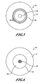
- FIGURE 4 illustrates a cross-sectional view of a first embodiment of a fiber optic cable 20 that provides single-mode delivery of light generated by the light source 14.
- the cable 20 includes two components, a glass core 24 having a first index of refraction n 1 and a cladding material 26 that surrounds the glass core 24.
- the cladding material 26 is preferably a polymer having an index of refraction n 2 that is lower than n 1 .
- these fibers are multimode because of the large core diameter and the large index difference.
- the cladding material 26 is preferably a polymer having an index of refraction n 2 that is just very slightly lower than n 1 .
- the diameter of the glass core 24 is approximately 30 ⁇ m to 100 ⁇ m.
- the polymer's (cladding's) index of refraction is increased by adding dopants, or the polymer is chosen to have an index just below that of fused silica, so the index difference with the core is very small, yet the index of the polymer is still lower than that of the core.
- the polymer is an acrylate with dopants and an indicator embedded within.
- the core can also be doped to lower its index of refraction by the use of a dopant such as florine to partially accomplish the objective of a lower refractive index difference with the polymer.
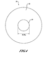
- FIGURE 5 shows an alternative to the fiber arrangement in FIGURE 4 .
- FIGURE 5 illustrates another single-mode fiber optic cable 32.
- the cable 32 includes a cladding material 34 that surrounds a glass core 36.
- the glass core 36 includes a hole 38 located in the center of the glass core 36 and a plurality of smaller holes 40 that surround the center hole 38 that are positioned near to the exterior edge of the glass core 36.
- the optical fiber can be made to be single mode.
- the hole pattern structures are consistent with those made for microstructured fibers, such as those produced for glass fibers by Crystal Fibre A/S of Denmark.
- the resulting fundamental mode of the fiber is a "hoop mode" whose intensity distribution is circularly symmetric and is peaked in between the outer radius of hole 38 and the holes 40.
- the evanescent field extends into the indicator-embedded, semiporous polymer cladding material 34, making the fiber sensitive to the indicator when triggered by a chemical agent.
- the light is contained in a hoop mode, and glass-member diameters of 30 ⁇ m may be obtained by sizing the holes, and the distances between them, appropriately. It should be noted that (while not shown in FIGURE 5 ) other designs with a ring of holes similar to those of the ring of holes 40, around central hole 38, or more concentric rings of holes inside the ring of holes 40 to achieve the desired results.
- FIGURE 6 illustrates another fiber optic cable 50 that includes a polymer or other type of cladding material 52 that surrounds a glass core 54.
- the glass core 54 includes a series of holes 56 and a solid region 58 around them.
- the holes 56 in the center assure that the light mode does not propagate in the center, and the cladding confines the light to be inside the region 58. Again, the light is propagating in a hoop mode.
- the glass core 54 may be made large enough ( ⁇ 30 microns) to be robust, and the evanescent field may be tailored to extend into the cladding of choice.
- the size of the center holes 38, 60 are in the range of approximately 1-50 ⁇ m.
- the size of the holes 30, 40, 56, 58, 76 are in the range of approximately 0.2-4 ⁇ m.
- the glass cores 24, 36, 54 may be doped in order to decrease its index of refraction n 1 .
Landscapes
- Physics & Mathematics (AREA)
- General Physics & Mathematics (AREA)
- Chemical & Material Sciences (AREA)
- Optics & Photonics (AREA)
- Biochemistry (AREA)
- Immunology (AREA)
- Life Sciences & Earth Sciences (AREA)
- Analytical Chemistry (AREA)
- Plasma & Fusion (AREA)
- General Health & Medical Sciences (AREA)
- Chemical Kinetics & Catalysis (AREA)
- Health & Medical Sciences (AREA)
- Pathology (AREA)
- Crystallography & Structural Chemistry (AREA)
- Engineering & Computer Science (AREA)
- Investigating Or Analysing Materials By Optical Means (AREA)
- Optical Fibers, Optical Fiber Cores, And Optical Fiber Bundles (AREA)
- Optical Couplings Of Light Guides (AREA)
Applications Claiming Priority (1)
| Application Number | Priority Date | Filing Date | Title |
|---|---|---|---|
| US11/757,904 US7702189B2 (en) | 2007-06-04 | 2007-06-04 | Fiber optic chemical sensor |
Publications (2)
| Publication Number | Publication Date |
|---|---|
| EP2000795A2 true EP2000795A2 (de) | 2008-12-10 |
| EP2000795A3 EP2000795A3 (de) | 2010-05-12 |
Family
ID=39713862
Family Applications (1)
| Application Number | Title | Priority Date | Filing Date |
|---|---|---|---|
| EP08157377A Withdrawn EP2000795A3 (de) | 2007-06-04 | 2008-06-01 | Verbesserter faseroptischer, chemischer Sensor |
Country Status (3)
| Country | Link |
|---|---|
| US (1) | US7702189B2 (de) |
| EP (1) | EP2000795A3 (de) |
| JP (1) | JP2009075065A (de) |
Cited By (2)
| Publication number | Priority date | Publication date | Assignee | Title |
|---|---|---|---|---|
| EP2249146A1 (de) * | 2009-05-08 | 2010-11-10 | Honeywell International Inc. | Photonenkristallfasersensor |
| WO2011119731A3 (en) * | 2010-03-23 | 2012-01-12 | Molex Incorporated | Optical fiber tapping device |
Families Citing this family (5)
| Publication number | Priority date | Publication date | Assignee | Title |
|---|---|---|---|---|
| JP2013534433A (ja) * | 2010-05-13 | 2013-09-05 | コーニンクレッカ フィリップス エヌ ヴェ | 光ファイバの形状再構成 |
| US10401343B1 (en) | 2010-09-28 | 2019-09-03 | Optech Ventures, Llc. | Gas sensing chemistry and sensors and sensing systems and method |
| KR101302412B1 (ko) | 2012-08-01 | 2013-09-02 | 광주과학기술원 | 화학 센서용 광섬유 |
| US9329341B2 (en) * | 2012-08-22 | 2016-05-03 | Telefonaktiebolaget L M Ericsson (Publ) | Radiation scribed waveguide coupling for photonic circuits |
| EP3340877A4 (de) | 2015-08-27 | 2019-06-05 | Shenzhen Darma Technology Co., Ltd. | Faseroptische sensoren und verfahren zur überwachung von mikrobewegungen |
Citations (3)
| Publication number | Priority date | Publication date | Assignee | Title |
|---|---|---|---|---|
| US6694067B1 (en) | 2001-01-05 | 2004-02-17 | Los Gatos Research | Cavity enhanced fiber optic and waveguide chemical sensor |
| US20040263856A1 (en) | 2002-11-13 | 2004-12-30 | Willig Reinhardt L | Photonic crystal interferometric fiber optical gyroscope system |
| WO2006108096A2 (en) | 2005-04-06 | 2006-10-12 | President And Fellows Of Harvard College | Method and apparatus for measuring and monitoring distances, physical properties, and phase changes of light reflected from a surface based on a ring-resonator |
Family Cites Families (13)
| Publication number | Priority date | Publication date | Assignee | Title |
|---|---|---|---|---|
| US4846548A (en) * | 1987-05-06 | 1989-07-11 | St&E, Inc. | Fiber optic which is an inherent chemical sensor |
| US4834496A (en) * | 1987-05-22 | 1989-05-30 | American Telephone And Telegraph Company, At&T Bell Laboratories | Optical fiber sensors for chemical detection |
| US5337376A (en) * | 1993-04-19 | 1994-08-09 | Hughes Aircraft Company | Chemically sensitive fiber optic cable |
| US5828798A (en) * | 1996-09-09 | 1998-10-27 | Hopenfeld; Joram | Looped fiber-optic sensor for the detection of substances |
| JPH10332584A (ja) * | 1997-06-03 | 1998-12-18 | Furukawa Electric Co Ltd:The | リングレーザ型ガスセンサ |
| JP2000275174A (ja) * | 1999-03-23 | 2000-10-06 | Gb Jieotei Inc | 可燃性炭化水素系ガス・溶液の検知用オプティクファイバーセンサ素子及び検出装置 |
| CA2386884C (en) * | 2001-05-29 | 2010-02-09 | Queen's University At Kingston | Optical loop ring-down |
| US7046362B2 (en) * | 2001-12-12 | 2006-05-16 | Trustees Of Princeton University | Fiber-optic based cavity ring-down spectroscopy apparatus |
| US6847771B2 (en) * | 2002-06-12 | 2005-01-25 | Corning Incorporated | Microstructured optical fibers and preforms and methods for fabricating microstructured optical fibers |
| US7388671B2 (en) * | 2005-10-18 | 2008-06-17 | Honeywell International, Inc. | Polarizing cavity for RFOG and method for sensing rotation rate of resonator |
| CA2656420A1 (en) * | 2006-06-29 | 2008-01-03 | The Board Of Trustees Of The Leland Stanford Junior University | Fiber optic sensor using a bragg fiber |
| US7518730B2 (en) * | 2007-02-27 | 2009-04-14 | Honeywell International Inc. | Apparatus and method for chemical sensing |
| US7483144B2 (en) * | 2007-03-02 | 2009-01-27 | Honeywell International, Inc. | Apparatus and method for resonant chemical and biological sensing |
-
2007
- 2007-06-04 US US11/757,904 patent/US7702189B2/en not_active Expired - Fee Related
-
2008
- 2008-06-01 EP EP08157377A patent/EP2000795A3/de not_active Withdrawn
- 2008-06-04 JP JP2008146734A patent/JP2009075065A/ja active Pending
Patent Citations (3)
| Publication number | Priority date | Publication date | Assignee | Title |
|---|---|---|---|---|
| US6694067B1 (en) | 2001-01-05 | 2004-02-17 | Los Gatos Research | Cavity enhanced fiber optic and waveguide chemical sensor |
| US20040263856A1 (en) | 2002-11-13 | 2004-12-30 | Willig Reinhardt L | Photonic crystal interferometric fiber optical gyroscope system |
| WO2006108096A2 (en) | 2005-04-06 | 2006-10-12 | President And Fellows Of Harvard College | Method and apparatus for measuring and monitoring distances, physical properties, and phase changes of light reflected from a surface based on a ring-resonator |
Cited By (4)
| Publication number | Priority date | Publication date | Assignee | Title |
|---|---|---|---|---|
| EP2249146A1 (de) * | 2009-05-08 | 2010-11-10 | Honeywell International Inc. | Photonenkristallfasersensor |
| US7952772B2 (en) | 2009-05-08 | 2011-05-31 | Honeywell International Inc. | Photonic crystal fiber sensor |
| WO2011119731A3 (en) * | 2010-03-23 | 2012-01-12 | Molex Incorporated | Optical fiber tapping device |
| US10197735B2 (en) | 2010-03-23 | 2019-02-05 | Molex, Llc | Optical fiber tapping device |
Also Published As
| Publication number | Publication date |
|---|---|
| US20090067775A1 (en) | 2009-03-12 |
| JP2009075065A (ja) | 2009-04-09 |
| EP2000795A3 (de) | 2010-05-12 |
| US7702189B2 (en) | 2010-04-20 |
Similar Documents
| Publication | Publication Date | Title |
|---|---|---|
| EP1965196B1 (de) | Vorrichtung und Verfahren für die resonante chemische und biologische Abtastung | |
| Sanders et al. | Hollow-core resonator fiber optic gyroscope using nodeless anti-resonant fiber | |
| EP2166377B1 (de) | Radiologischer und nuklearer optischer Sensor | |
| US7702189B2 (en) | Fiber optic chemical sensor | |
| US6879752B1 (en) | Film spacer for setting the gap between an optical coupler and a whispering-gallery mode optical resonator | |
| US20130070252A1 (en) | Systems and methods for a hollow core resonant filter | |
| EP1923693A1 (de) | Vorrichtung und Verfahren für die chemische und biologische Abtastung | |
| AU2013100784A4 (en) | An optical refractive index measuring system based on speckel correlation | |
| JP2009025305A (ja) | 化学薬剤、生物学的薬剤及び放射線薬剤検出用の装置及び方法 | |
| US20110295511A1 (en) | Apparatus and method for detecting the presence of an agent | |
| US9291774B1 (en) | Polarization dependent whispering gallery modes in microspheres | |
| Betta et al. | An optical fiber-based technique for continuous-level sensing | |
| US20220342145A1 (en) | Composed multicore optical fiber device | |
| US7957005B2 (en) | Fiber optic apparatus and method for sensing hazardous materials | |
| Ding et al. | Sapphire fiber Bragg grating coupled with graded-index fiber lens | |
| Yacoby et al. | Optical resonators as a platform for induced-loss sensing with a demonstration of a γ radiation sensor | |
| CN1466696A (zh) | 采用包层模式耦合的光纤总线、调制器、检测器以及发射器 | |
| Wei et al. | Direct laser writing of polymer micro-ring resonator ultrasonic sensors | |
| RU99197U1 (ru) | Микрорезонаторный волоконно-оптический преобразователь физических величин | |
| WO2000070307A2 (en) | A sensor and a method for determining the direction and the amplitude of a bend | |
| Bestwick | Active silicon integrated optical circuits | |
| Jin et al. | Reflective Tilted Fiber Bragg Grating Refractometer by Interacting with Multimode Fiber | |
| JP2002139405A (ja) | 半導体レーザモジュールの測定方法 | |
| Guo et al. | Two-dimensional fiber-optic vector vibroscope using only one multi-mode tilted fiber grating | |
| JP2000321468A (ja) | 光パワー検出装置 |
Legal Events
| Date | Code | Title | Description |
|---|---|---|---|
| PUAI | Public reference made under article 153(3) epc to a published international application that has entered the european phase |
Free format text: ORIGINAL CODE: 0009012 |
|
| 17P | Request for examination filed |
Effective date: 20080601 |
|
| AK | Designated contracting states |
Kind code of ref document: A2 Designated state(s): AT BE BG CH CY CZ DE DK EE ES FI FR GB GR HR HU IE IS IT LI LT LU LV MC MT NL NO PL PT RO SE SI SK TR |
|
| AX | Request for extension of the european patent |
Extension state: AL BA MK RS |
|
| PUAL | Search report despatched |
Free format text: ORIGINAL CODE: 0009013 |
|
| AK | Designated contracting states |
Kind code of ref document: A3 Designated state(s): AT BE BG CH CY CZ DE DK EE ES FI FR GB GR HR HU IE IS IT LI LT LU LV MC MT NL NO PL PT RO SE SI SK TR |
|
| AX | Request for extension of the european patent |
Extension state: AL BA MK RS |
|
| 17Q | First examination report despatched |
Effective date: 20100604 |
|
| AKX | Designation fees paid |
Designated state(s): DE FR |
|
| STAA | Information on the status of an ep patent application or granted ep patent |
Free format text: STATUS: THE APPLICATION IS DEEMED TO BE WITHDRAWN |
|
| 18D | Application deemed to be withdrawn |
Effective date: 20150106 |