EP2000782A2 - Photoelectric encoder - Google Patents
Photoelectric encoder Download PDFInfo
- Publication number
- EP2000782A2 EP2000782A2 EP08156987A EP08156987A EP2000782A2 EP 2000782 A2 EP2000782 A2 EP 2000782A2 EP 08156987 A EP08156987 A EP 08156987A EP 08156987 A EP08156987 A EP 08156987A EP 2000782 A2 EP2000782 A2 EP 2000782A2
- Authority
- EP
- European Patent Office
- Prior art keywords
- protective material
- transparent protective
- scale
- photoelectric encoder
- grating
- Prior art date
- Legal status (The legal status is an assumption and is not a legal conclusion. Google has not performed a legal analysis and makes no representation as to the accuracy of the status listed.)
- Granted
Links
Images


Classifications
-
- G—PHYSICS
- G01—MEASURING; TESTING
- G01D—MEASURING NOT SPECIALLY ADAPTED FOR A SPECIFIC VARIABLE; ARRANGEMENTS FOR MEASURING TWO OR MORE VARIABLES NOT COVERED IN A SINGLE OTHER SUBCLASS; TARIFF METERING APPARATUS; MEASURING OR TESTING NOT OTHERWISE PROVIDED FOR
- G01D5/00—Mechanical means for transferring the output of a sensing member; Means for converting the output of a sensing member to another variable where the form or nature of the sensing member does not constrain the means for converting; Transducers not specially adapted for a specific variable
- G01D5/26—Mechanical means for transferring the output of a sensing member; Means for converting the output of a sensing member to another variable where the form or nature of the sensing member does not constrain the means for converting; Transducers not specially adapted for a specific variable characterised by optical transfer means, i.e. using infrared, visible, or ultraviolet light
- G01D5/32—Mechanical means for transferring the output of a sensing member; Means for converting the output of a sensing member to another variable where the form or nature of the sensing member does not constrain the means for converting; Transducers not specially adapted for a specific variable characterised by optical transfer means, i.e. using infrared, visible, or ultraviolet light with attenuation or whole or partial obturation of beams of light
- G01D5/34—Mechanical means for transferring the output of a sensing member; Means for converting the output of a sensing member to another variable where the form or nature of the sensing member does not constrain the means for converting; Transducers not specially adapted for a specific variable characterised by optical transfer means, i.e. using infrared, visible, or ultraviolet light with attenuation or whole or partial obturation of beams of light the beams of light being detected by photocells
- G01D5/347—Mechanical means for transferring the output of a sensing member; Means for converting the output of a sensing member to another variable where the form or nature of the sensing member does not constrain the means for converting; Transducers not specially adapted for a specific variable characterised by optical transfer means, i.e. using infrared, visible, or ultraviolet light with attenuation or whole or partial obturation of beams of light the beams of light being detected by photocells using displacement encoding scales
Definitions
- the present invention relates to a photoelectric encoder and in particular to a photoelectric encoder capable of improving reliability for scale dirt, stabilizing the signal strength, and improving the signal detection efficiency, suited for use as a photoelectric encoder including a scale having an optical grating and an image forming optical system which can move relatively to the scale, adapted to detect relative displacement of the scale using interference of light.
- a photoelectric encoder of grating interference type for detecting relative displacement of a scale using interference of light is known as described in patent documents 1 to 3.
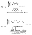
- the photoelectric encoder of grating interference type is of transmission type, light projected onto an index scale 12 from a light source 10 and diffracted on a grating 13 is again diffracted on a grating 15 on a main scale (simply, referred as scale) 14 to produce a light and dark interference fringe, this interference fringe is detected on a light reception element 20, and displacement of the scale 14 is detected, as shown in FIG. 1 .
- the photoelectric encoder of grating interference type is of reflection type
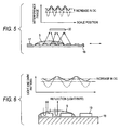
- an interference fringe is generated using light diffraction/interference through a phase grating 17 on a scale 16 as shown in FIG. 2 as with the transmission type shown in FIG. 1 or a portion where a phase grating 19 of a scale 18 does not exist is reflected and becomes a light part and a portion where the phase grating 19 exists becomes a dark part because of interference in such a manner that the phase difference between reflected light on the surface of the phase grating 19 and that on the bottom of the phase grating 19 becomes light wavelength/2 (a value obtained by dividing the light wavelength by 2), as shown in FIG. 3 .
- the transmission type and the reflection type have a problem of a decrease in the signal strength if dirt exists on the scale surface. That is, in the transmission type in FIGs. 1 and 2 , if the light path length changes due to refraction because of dirt s on the scale surface and the direct current (DC) component of an interference fringe arriving at the light reception element 20 increases, worsening the contrast of the interference fringe, as in FIGs. 4 and 5 . On the other hand, in the reflection type in FIG. 3 , a phase difference changes due to dirt S, no interference occurs, and the direct current (DC) component increases, worsening the contrast of the interference fringe, as in FIG. 6 .
- a photoelectric encoder including a scale and an image forming optical system which move relatively to each other, adapted to detect relative displacement of the scale, wherein a transparent protective material having a thickness equal to or greater than a depth of focus of the image forming optical system is disposed on a surface of the scale where a grating is provided.
- the transparent protective material can be transparent tape bonded to the surface of the scale where the grating is provided or a transparent protective material applied to the surface of the scale where the grating is provided.
- the surface of the transparent protective material can have hydrophilicity or lipophilicity by using an oxide such as a titanium oxide, a titanium dioxide or the like. More specifically, the surface of the transparent protective material may be covered by a titanium oxide film or the transparent protective material may be made of a titanium oxide, so that the transparent protective material can have hydrophilicity. The surface of the transparent protective material may be covered by a titanium dioxide film or the transparent protective material may be made of a titanium dioxide, so that the transparent protective material can have lipophilicity. In an environment in which water is used, the transparent protective material has hydrophilicity, so that it is possible to prevent the water droplet from forming on the transparent protective material or the water from being accumulated on the transparent protective material because the water spreads on the transparent protective material.
- the transparent protective material has lipophilicity, so that it is possible to prevent the oil droplet from forming on the transparent protective material or the oil from being accumulated on the transparent protective material because the oil spreads on the transparent protective material. Therefore, it is possible to prevent the optical influence by the water droplet or oil droplet from occurring.
- the transparent protective material can have the characteristic of a filter.
- the image forming optical system can include an aperture.
- the transparent protective material has the thickness equal to or greater than the depth of focus (DOF) of the image forming optical system and thus the effect on image formation is small. Therefore, reliability for scale dirt is improved, the signal strength is stabilized, and the signal detection efficiency is improved. Moreover, the dirt portion spreads on he transparent protective material by means of the transparent protective material having hydrophilicity or lipophilicity, for example, the refractive power caused by the scale dirt lessens, and the interference fringe scarcely changes. Therefore, reliability for scale dirt is further improved, the signal strength is further stabilized, and the signal detection efficiency is further improved.
- DOF depth of focus
- a scale 14 having a grating 15 is formed by (a) forming a film 32 which becomes a grating on a base 30 made of glass or metal, for example, (b) applying a resist 34 onto the film, (c) exposing to light and removing a part of the resist 34, (d) etching and removing a part of the film 32, and (e) peeling off the resist 34, as shown in FIG. 7 .
- a transparent protective material is disposed by bonding transparent tape 40 made of glass or resin (PET film, etc.,) to the grating 15 side surface of the scale 14 by adhesiveness of the tape or with an adhesive as shown in (f), evaporating a transparent protective material 42 onto the grating side surface as shown in (g), applying a transparent protective material 42 to the grating side surface with a spray 44 as shown in (h), or immersing the whole in a protective material tank 46 as shown in (i).
- transparent tape 40 made of glass or resin (PET film, etc.
- a thickness t of each of the transparent protective materials 40 and 42 is equal to or greater than the depth of focus (DOF) of an image forming optical system.
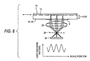
- FIG. 8 shows a first embodiment of the invention applied to a transmission encoder like that in FIG. 1 having an image forming optical system made of a lens 22.
- a transparent protective material 40 or 42 is disposed on a grating 15 side surface of a scale 14, whereby dirt S is deposited on the transparent protective material 40 or 42 rather than on the grating 15 face of the scale 14 and the dirt portion spreads because of hydrophilicity or lipophilicity. Therefore, the refractive power lessens and an interference fringe scarcely changes.
- the thickness t of the transparent protective material 40 or 42 is larger than the DOF and thus the effect on image formation through the lens 22 is small.
- the DOF lessens, so that the thickness t of the transparent protective material 40 or 42 can be thinned.
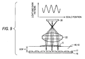
- FIG. 9 shows a second embodiment of the invention applied to a reflection encoder as shown in FIG. 2 .
- FIG. 10 shows a third embodiment of the invention applied to a reflection encoder as shown in FIG. 3 .
- the portion of dirt S spreads and thus an interference fringe scarcely changes.
- thickness t of a transparent protective material 40 or 42 is larger than the DOF and thus the effect on image formation through a lens 22 is small.
- the transparent protective material can be implemented as a band-pass filter formed by multilayer coating by evaporation, for example, and can be provided with a function of removing external visible light, etc., for example, when an infrared light source is used.
- the aperture 24 may be added to the focal position of the lens 22, and in this case, since DOF lessens, the thickness t of the transparent protective material 40 or 42 can be thinned.
Landscapes
- Physics & Mathematics (AREA)
- General Physics & Mathematics (AREA)
- Optical Transform (AREA)
Abstract
Description
- The present invention relates to a photoelectric encoder and in particular to a photoelectric encoder capable of improving reliability for scale dirt, stabilizing the signal strength, and improving the signal detection efficiency, suited for use as a photoelectric encoder including a scale having an optical grating and an image forming optical system which can move relatively to the scale, adapted to detect relative displacement of the scale using interference of light.
- A photoelectric encoder of grating interference type for detecting relative displacement of a scale using interference of light is known as described in patent documents 1 to 3.
- If the photoelectric encoder of grating interference type is of transmission type, light projected onto an
index scale 12 from alight source 10 and diffracted on agrating 13 is again diffracted on agrating 15 on a main scale (simply, referred as scale) 14 to produce a light and dark interference fringe, this interference fringe is detected on alight reception element 20, and displacement of thescale 14 is detected, as shown inFIG. 1 . - On the other hand, if the photoelectric encoder of grating interference type is of reflection type, an interference fringe is generated using light diffraction/interference through a phase grating 17 on a
scale 16 as shown inFIG. 2 as with the transmission type shown inFIG. 1 or a portion where a phase grating 19 of ascale 18 does not exist is reflected and becomes a light part and a portion where thephase grating 19 exists becomes a dark part because of interference in such a manner that the phase difference between reflected light on the surface of the phase grating 19 and that on the bottom of the phase grating 19 becomes light wavelength/2 (a value obtained by dividing the light wavelength by 2), as shown inFIG. 3 . -
- [Patent document 1] Japanese Patent Application Publication No.
Hei. 2-167427 - [Patent document 2] Japanese Patent Application Publication No.
Hei. 2-167428 - [Patent document 3] Japanese Patent Application Publication No.
Hei. 2-176420 - [Patent document 4] Japanese Patent Application Publication No.
2004-264295 - However, the transmission type and the reflection type have a problem of a decrease in the signal strength if dirt exists on the scale surface. That is, in the transmission type in
FIGs. 1 and2 , if the light path length changes due to refraction because of dirt s on the scale surface and the direct current (DC) component of an interference fringe arriving at thelight reception element 20 increases, worsening the contrast of the interference fringe, as inFIGs. 4 and5 . On the other hand, in the reflection type inFIG. 3 , a phase difference changes due to dirt S, no interference occurs, and the direct current (DC) component increases, worsening the contrast of the interference fringe, as inFIG. 6 . - Such a problem is also involved in a photoelectric encoder including a lens optical system for image formation (also called image forming optical system) as described in patent document 4.
- It is therefore an object of the invention to improve reliability for scale dirt, stabilize the signal strength, and improve the signal detection efficiency.
- To accomplish the object, according to the invention, there is provided a photoelectric encoder including a scale and an image forming optical system which move relatively to each other, adapted to detect relative displacement of the scale, wherein a transparent protective material having a thickness equal to or greater than a depth of focus of the image forming optical system is disposed on a surface of the scale where a grating is provided.
- The transparent protective material can be transparent tape bonded to the surface of the scale where the grating is provided or a transparent protective material applied to the surface of the scale where the grating is provided.
- The surface of the transparent protective material can have hydrophilicity or lipophilicity by using an oxide such as a titanium oxide, a titanium dioxide or the like. More specifically, the surface of the transparent protective material may be covered by a titanium oxide film or the transparent protective material may be made of a titanium oxide, so that the transparent protective material can have hydrophilicity. The surface of the transparent protective material may be covered by a titanium dioxide film or the transparent protective material may be made of a titanium dioxide, so that the transparent protective material can have lipophilicity. In an environment in which water is used, the transparent protective material has hydrophilicity, so that it is possible to prevent the water droplet from forming on the transparent protective material or the water from being accumulated on the transparent protective material because the water spreads on the transparent protective material. In an environment in which oil is used as in a machine tool, the transparent protective material has lipophilicity, so that it is possible to prevent the oil droplet from forming on the transparent protective material or the oil from being accumulated on the transparent protective material because the oil spreads on the transparent protective material. Therefore, it is possible to prevent the optical influence by the water droplet or oil droplet from occurring.
- The transparent protective material can have the characteristic of a filter.
- The image forming optical system can include an aperture.
- According to the invention, the transparent protective material has the thickness equal to or greater than the depth of focus (DOF) of the image forming optical system and thus the effect on image formation is small. Therefore, reliability for scale dirt is improved, the signal strength is stabilized, and the signal detection efficiency is improved. Moreover, the dirt portion spreads on he transparent protective material by means of the transparent protective material having hydrophilicity or lipophilicity, for example, the refractive power caused by the scale dirt lessens, and the interference fringe scarcely changes. Therefore, reliability for scale dirt is further improved, the signal strength is further stabilized, and the signal detection efficiency is further improved.
- In the accompanying drawings:
-
FIG. 1 is a drawing to show the measurement principle of a grating interference type transmission photoelectric encoder in a related art; -
FIG. 2 is a drawing to show the measurement principle of an example of a grating interference type transmission photoelectric encoder in a related art; -
FIG. 3 is a drawing to show the measurement principle of another example of a grating interference type transmission photoelectric encoder in a related art; -
FIG. 4 is a drawing to show change in interference fringe contrast caused by dirt in the transmission encoder inFIG. 1 ; -
FIG. 5 is a drawing to show change in interference fringe contrast caused by dirt in the reflection encoder inFIG. 2 ; -
FIG. 6 is a drawing to show phase difference change caused by dirt in the reflection encoder inFIG. 3 ; -
FIG. 7 is a drawing to show a disposing method of a transparent protective material for a scale of a photoelectric encoder according to the invention; -
FIG. 8 is a drawing to show a first embodiment of the invention applied to a transmission encoder like that inFIG. 1 ; -
FIG. 9 is a drawing to show a second embodiment of the invention applied to a reflection encoder like that inFIG. 2 ; and -
FIG. 10 is a drawing to show a third embodiment of the invention applied to a reflection encoder like that inFIG. 3 . - Embodiments of the invention will be discussed in detail with reference to the accompanying drawings.
To begin with, a disposing method of a transparent protective material will be discussed. - A
scale 14 having agrating 15 is formed by (a) forming afilm 32 which becomes a grating on abase 30 made of glass or metal, for example, (b) applying aresist 34 onto the film, (c) exposing to light and removing a part of theresist 34, (d) etching and removing a part of thefilm 32, and (e) peeling off theresist 34, as shown inFIG. 7 . After forming thegrating 15, a transparent protective material is disposed by bondingtransparent tape 40 made of glass or resin (PET film, etc.,) to the grating 15 side surface of thescale 14 by adhesiveness of the tape or with an adhesive as shown in (f), evaporating a transparentprotective material 42 onto the grating side surface as shown in (g), applying a transparentprotective material 42 to the grating side surface with aspray 44 as shown in (h), or immersing the whole in aprotective material tank 46 as shown in (i). - A thickness t of each of the transparent
protective materials -
FIG. 8 shows a first embodiment of the invention applied to a transmission encoder like that inFIG. 1 having an image forming optical system made of alens 22. As shown inFIG. 8 , a transparentprotective material scale 14, whereby dirt S is deposited on the transparentprotective material scale 14 and the dirt portion spreads because of hydrophilicity or lipophilicity. Therefore, the refractive power lessens and an interference fringe scarcely changes. Further, the thickness t of the transparentprotective material lens 22 is small. - Particularly, if an
aperture 24 is added to the focal position of thelens 22 as indicated by the dashed line in the figure, the DOF lessens, so that the thickness t of the transparentprotective material - Next,
FIG. 9 shows a second embodiment of the invention applied to a reflection encoder as shown inFIG. 2 . - Also in the embodiment, dirt S spreads on a transparent
protective material protective material lens 22 is small. - Next,
FIG. 10 shows a third embodiment of the invention applied to a reflection encoder as shown inFIG. 3 . - Also in the embodiment, the portion of dirt S spreads and thus an interference fringe scarcely changes. Further, thickness t of a transparent
protective material lens 22 is small. - The transparent protective material can be implemented as a band-pass filter formed by multilayer coating by evaporation, for example, and can be provided with a function of removing external visible light, etc., for example, when an infrared light source is used.
Further, in the reflection encoder as shown inFigs. 2 and 3 , as with the first embodiment ofFig. 1 , theaperture 24 may be added to the focal position of thelens 22, and in this case, since DOF lessens, the thickness t of the transparentprotective material
Claims (10)
- A photoelectric encoder comprising a scale and an image forming optical system which move relatively to each other, adapted to detect relative displacement of the scale,
wherein a transparent protective material having a thickness equal to or greater than a depth of focus of the image forming optical system is disposed on a surface of the scale where a grating is provided. - The photoelectric encoder as claimed in claim 1 wherein the transparent protective material is a transparent tape bonded to the surface of the scale where the grating is provided.
- The photoelectric encoder as claimed in claim 1 wherein the transparent protective material is a transparent protective material applied to the surface of the scale where the grating is provided.
- The photoelectric encoder as claimed in any of claims 1 to 3 wherein a surface of the transparent protective material has hydrophilicity.
- The photoelectric encoder as claimed in any of claims 1 to 3 wherein a surface of the transparent protective material has lipophilicity.
- The photoelectric encoder as claimed in any of claims 1 to 5 wherein the transparent protective material has the characteristic of a filter.
- The photoelectric encoder as claimed in any of claims 1 to 6 wherein the image forming optical system includes an aperture.
- The photoelectric encoder as claimed in claim 4 wherein the transparent protective material is made of a titanium oxide.
- The photoelectric encoder as claimed in claim 5 wherein the transparent protective material is made of a titanium dioxide.
- The photoelectric encoder as claimed in claim 6 wherein the transparent protective material is a band-pass filter formed by multilayer coating by evaporation.
Applications Claiming Priority (1)
| Application Number | Priority Date | Filing Date | Title |
|---|---|---|---|
| JP2007140557A JP2008292406A (en) | 2007-05-28 | 2007-05-28 | Photoelectric encoder |
Publications (3)
| Publication Number | Publication Date |
|---|---|
| EP2000782A2 true EP2000782A2 (en) | 2008-12-10 |
| EP2000782A3 EP2000782A3 (en) | 2011-10-05 |
| EP2000782B1 EP2000782B1 (en) | 2016-02-17 |
Family
ID=39876644
Family Applications (1)
| Application Number | Title | Priority Date | Filing Date |
|---|---|---|---|
| EP08156987.3A Active EP2000782B1 (en) | 2007-05-28 | 2008-05-27 | Photoelectric encoder |
Country Status (4)
| Country | Link |
|---|---|
| US (1) | US7642505B2 (en) |
| EP (1) | EP2000782B1 (en) |
| JP (1) | JP2008292406A (en) |
| CN (1) | CN101315290B (en) |
Families Citing this family (7)
| Publication number | Priority date | Publication date | Assignee | Title |
|---|---|---|---|---|
| NL2003638A (en) | 2008-12-03 | 2010-06-07 | Asml Netherlands Bv | Lithographic apparatus and device manufacturing method. |
| JP2011021909A (en) * | 2009-07-13 | 2011-02-03 | Nikon Corp | Scale for encoder and encoder apparatus |
| JP5893857B2 (en) * | 2011-06-24 | 2016-03-23 | 株式会社ミツトヨ | Scale scale protection structure |
| EP2775271B1 (en) * | 2011-10-31 | 2019-03-20 | NSK Ltd. | Optical scale, method for manufacturing optical scale, and optical encoder |
| JP6169392B2 (en) * | 2013-03-29 | 2017-07-26 | 株式会社ミツトヨ | Photoelectric encoder |
| JP6383460B1 (en) * | 2017-05-31 | 2018-08-29 | 浜松ホトニクス株式会社 | Light receiving module for encoder and encoder |
| JP7252809B2 (en) * | 2019-03-28 | 2023-04-05 | 株式会社ミツトヨ | Photoelectric encoders and calculation methods in photoelectric encoders |
Citations (4)
| Publication number | Priority date | Publication date | Assignee | Title |
|---|---|---|---|---|
| JPH02167427A (en) | 1988-12-21 | 1990-06-27 | Mitsutoyo Corp | Grating interference type displacement gauge |
| JPH02167428A (en) | 1988-12-21 | 1990-06-27 | Mitsutoyo Corp | Grating interference type displacement gauge |
| JPH02176420A (en) | 1988-12-27 | 1990-07-09 | Mitsutoyo Corp | Lattice interference type displacement gage and its scale |
| JP2004264295A (en) | 2003-02-12 | 2004-09-24 | Mitsutoyo Corp | Photoelectric encoder |
Family Cites Families (8)
| Publication number | Priority date | Publication date | Assignee | Title |
|---|---|---|---|---|
| EP0385418B1 (en) * | 1989-02-28 | 1995-01-18 | Sony Magnescale, Inc. | Hologram scale having moisture resistance |
| DE4338680C1 (en) * | 1993-11-12 | 1995-03-23 | Heidenhain Gmbh Dr Johannes | Length-measuring or angle-measuring device |
| DE19738751A1 (en) * | 1996-09-10 | 1998-03-12 | Harmonic Drive Systems | Optical coder with slotted plate and shadowing layer |
| JPH11118677A (en) * | 1997-10-14 | 1999-04-30 | Hitachi Ltd | Inspection object for calibration, manufacturing method thereof, calibration method of inspection device, and inspection device |
| JP4869505B2 (en) * | 2001-06-27 | 2012-02-08 | 株式会社ミツトヨ | Encoder sliding mechanism |
| JP2004198179A (en) * | 2002-12-17 | 2004-07-15 | Yaskawa Electric Corp | Optical encoder |
| EP1447648B1 (en) * | 2003-02-12 | 2015-07-01 | Mitutoyo Corporation | Optical Encoder |
| JP2005315610A (en) * | 2004-04-27 | 2005-11-10 | Matsushita Electric Ind Co Ltd | Encoder device |
-
2007
- 2007-05-28 JP JP2007140557A patent/JP2008292406A/en active Pending
-
2008
- 2008-05-27 EP EP08156987.3A patent/EP2000782B1/en active Active
- 2008-05-28 US US12/128,201 patent/US7642505B2/en active Active
- 2008-05-28 CN CN2008101093510A patent/CN101315290B/en not_active Expired - Fee Related
Patent Citations (4)
| Publication number | Priority date | Publication date | Assignee | Title |
|---|---|---|---|---|
| JPH02167427A (en) | 1988-12-21 | 1990-06-27 | Mitsutoyo Corp | Grating interference type displacement gauge |
| JPH02167428A (en) | 1988-12-21 | 1990-06-27 | Mitsutoyo Corp | Grating interference type displacement gauge |
| JPH02176420A (en) | 1988-12-27 | 1990-07-09 | Mitsutoyo Corp | Lattice interference type displacement gage and its scale |
| JP2004264295A (en) | 2003-02-12 | 2004-09-24 | Mitsutoyo Corp | Photoelectric encoder |
Also Published As
| Publication number | Publication date |
|---|---|
| EP2000782B1 (en) | 2016-02-17 |
| EP2000782A3 (en) | 2011-10-05 |
| JP2008292406A (en) | 2008-12-04 |
| US20080302953A1 (en) | 2008-12-11 |
| US7642505B2 (en) | 2010-01-05 |
| CN101315290A (en) | 2008-12-03 |
| CN101315290B (en) | 2011-12-21 |
Similar Documents
| Publication | Publication Date | Title |
|---|---|---|
| US7642505B2 (en) | Photoelectric encoder with a transparent protective material having a thickness equal to or greater than a depth of focus of an image forming optical system disposed on the surface of a scale | |
| JP4971047B2 (en) | Surface reflective encoder scale and surface reflective encoder using the same | |
| EP1557701A1 (en) | Photoelectric encoder and method of manufacturing scales | |
| US20210063318A1 (en) | Detection device for detecting contamination | |
| US8816269B2 (en) | Reflective optical scale for encoder and reflective optical encoder | |
| US20060140538A1 (en) | Surface reflection type phase grating | |
| JPH06229781A (en) | Displacement measuring equipment | |
| JP6552052B2 (en) | Toner adhesion amount sensor | |
| JP2005147828A (en) | Displacement detector | |
| US5696584A (en) | Phase grating having an unprotected relief structure with a grating structure that causes destructive interference of reflections | |
| JPH05232318A (en) | Reflection type hologram scale | |
| US11592525B2 (en) | Filter device for an optical sensor | |
| CN112147729A (en) | Grating member and method for manufacturing same | |
| JP5443452B2 (en) | Optical scale and optical unit including the same | |
| EP3926372B1 (en) | Optical component | |
| EP4124893A1 (en) | Optical element, light receiving device, distance measurement apparatus, mobile object, and optical element manufacturing method | |
| JP2007172817A (en) | Information carrier | |
| JP2004037341A (en) | Manufacturing method of photoelectric encoder and scale | |
| JP5789409B2 (en) | Optical scale | |
| JP3125557B2 (en) | Imaging device | |
| JP4394515B2 (en) | Scale manufacturing method | |
| JP2010002324A (en) | Optical encoder | |
| JP6996375B2 (en) | Liquid detection sensor | |
| JPH103691A (en) | Optical pickup device | |
| JPH11149036A (en) | Auto focus camera |
Legal Events
| Date | Code | Title | Description |
|---|---|---|---|
| PUAI | Public reference made under article 153(3) epc to a published international application that has entered the european phase |
Free format text: ORIGINAL CODE: 0009012 |
|
| AK | Designated contracting states |
Kind code of ref document: A2 Designated state(s): AT BE BG CH CY CZ DE DK EE ES FI FR GB GR HR HU IE IS IT LI LT LU LV MC MT NL NO PL PT RO SE SI SK TR |
|
| AX | Request for extension of the european patent |
Extension state: AL BA MK RS |
|
| RIN1 | Information on inventor provided before grant (corrected) |
Inventor name: MIZUTANI, MIYAKO |
|
| PUAL | Search report despatched |
Free format text: ORIGINAL CODE: 0009013 |
|
| AK | Designated contracting states |
Kind code of ref document: A3 Designated state(s): AT BE BG CH CY CZ DE DK EE ES FI FR GB GR HR HU IE IS IT LI LT LU LV MC MT NL NO PL PT RO SE SI SK TR |
|
| AX | Request for extension of the european patent |
Extension state: AL BA MK RS |
|
| RIC1 | Information provided on ipc code assigned before grant |
Ipc: G01D 5/347 20060101AFI20110831BHEP |
|
| 17P | Request for examination filed |
Effective date: 20120403 |
|
| AKX | Designation fees paid |
Designated state(s): DE FR GB |
|
| GRAP | Despatch of communication of intention to grant a patent |
Free format text: ORIGINAL CODE: EPIDOSNIGR1 |
|
| INTG | Intention to grant announced |
Effective date: 20151009 |
|
| GRAS | Grant fee paid |
Free format text: ORIGINAL CODE: EPIDOSNIGR3 |
|
| GRAA | (expected) grant |
Free format text: ORIGINAL CODE: 0009210 |
|
| AK | Designated contracting states |
Kind code of ref document: B1 Designated state(s): DE FR GB |
|
| REG | Reference to a national code |
Ref country code: GB Ref legal event code: FG4D |
|
| REG | Reference to a national code |
Ref country code: DE Ref legal event code: R096 Ref document number: 602008042360 Country of ref document: DE |
|
| REG | Reference to a national code |
Ref country code: FR Ref legal event code: PLFP Year of fee payment: 9 |
|
| REG | Reference to a national code |
Ref country code: DE Ref legal event code: R097 Ref document number: 602008042360 Country of ref document: DE |
|
| PLBE | No opposition filed within time limit |
Free format text: ORIGINAL CODE: 0009261 |
|
| STAA | Information on the status of an ep patent application or granted ep patent |
Free format text: STATUS: NO OPPOSITION FILED WITHIN TIME LIMIT |
|
| 26N | No opposition filed |
Effective date: 20161118 |
|
| REG | Reference to a national code |
Ref country code: FR Ref legal event code: PLFP Year of fee payment: 10 |
|
| REG | Reference to a national code |
Ref country code: FR Ref legal event code: PLFP Year of fee payment: 11 |
|
| PGFP | Annual fee paid to national office [announced via postgrant information from national office to epo] |
Ref country code: FR Payment date: 20200522 Year of fee payment: 13 |
|
| PGFP | Annual fee paid to national office [announced via postgrant information from national office to epo] |
Ref country code: GB Payment date: 20200527 Year of fee payment: 13 |
|
| GBPC | Gb: european patent ceased through non-payment of renewal fee |
Effective date: 20210527 |
|
| PG25 | Lapsed in a contracting state [announced via postgrant information from national office to epo] |
Ref country code: GB Free format text: LAPSE BECAUSE OF NON-PAYMENT OF DUE FEES Effective date: 20210527 |
|
| PG25 | Lapsed in a contracting state [announced via postgrant information from national office to epo] |
Ref country code: FR Free format text: LAPSE BECAUSE OF NON-PAYMENT OF DUE FEES Effective date: 20210531 |
|
| PGFP | Annual fee paid to national office [announced via postgrant information from national office to epo] |
Ref country code: DE Payment date: 20250521 Year of fee payment: 18 |