EP2000748A2 - Collector element to generate heat from sun radiation and protective cover therefor - Google Patents
Collector element to generate heat from sun radiation and protective cover therefor Download PDFInfo
- Publication number
- EP2000748A2 EP2000748A2 EP08157819A EP08157819A EP2000748A2 EP 2000748 A2 EP2000748 A2 EP 2000748A2 EP 08157819 A EP08157819 A EP 08157819A EP 08157819 A EP08157819 A EP 08157819A EP 2000748 A2 EP2000748 A2 EP 2000748A2
- Authority
- EP
- European Patent Office
- Prior art keywords
- collector
- absorber
- elements
- holder
- tube
- Prior art date
- Legal status (The legal status is an assumption and is not a legal conclusion. Google has not performed a legal analysis and makes no representation as to the accuracy of the status listed.)
- Withdrawn
Links
Images


Classifications
-
- F—MECHANICAL ENGINEERING; LIGHTING; HEATING; WEAPONS; BLASTING
- F24—HEATING; RANGES; VENTILATING
- F24S—SOLAR HEAT COLLECTORS; SOLAR HEAT SYSTEMS
- F24S23/00—Arrangements for concentrating solar-rays for solar heat collectors
- F24S23/70—Arrangements for concentrating solar-rays for solar heat collectors with reflectors
- F24S23/77—Arrangements for concentrating solar-rays for solar heat collectors with reflectors with flat reflective plates
-
- F—MECHANICAL ENGINEERING; LIGHTING; HEATING; WEAPONS; BLASTING
- F24—HEATING; RANGES; VENTILATING
- F24S—SOLAR HEAT COLLECTORS; SOLAR HEAT SYSTEMS
- F24S10/00—Solar heat collectors using working fluids
- F24S10/40—Solar heat collectors using working fluids in absorbing elements surrounded by transparent enclosures, e.g. evacuated solar collectors
- F24S10/45—Solar heat collectors using working fluids in absorbing elements surrounded by transparent enclosures, e.g. evacuated solar collectors the enclosure being cylindrical
-
- F—MECHANICAL ENGINEERING; LIGHTING; HEATING; WEAPONS; BLASTING
- F24—HEATING; RANGES; VENTILATING
- F24S—SOLAR HEAT COLLECTORS; SOLAR HEAT SYSTEMS
- F24S10/00—Solar heat collectors using working fluids
- F24S10/70—Solar heat collectors using working fluids the working fluids being conveyed through tubular absorbing conduits
- F24S10/74—Solar heat collectors using working fluids the working fluids being conveyed through tubular absorbing conduits the tubular conduits are not fixed to heat absorbing plates and are not touching each other
- F24S10/742—Solar heat collectors using working fluids the working fluids being conveyed through tubular absorbing conduits the tubular conduits are not fixed to heat absorbing plates and are not touching each other the conduits being parallel to each other
-
- F—MECHANICAL ENGINEERING; LIGHTING; HEATING; WEAPONS; BLASTING
- F24—HEATING; RANGES; VENTILATING
- F24S—SOLAR HEAT COLLECTORS; SOLAR HEAT SYSTEMS
- F24S25/00—Arrangement of stationary mountings or supports for solar heat collector modules
-
- F—MECHANICAL ENGINEERING; LIGHTING; HEATING; WEAPONS; BLASTING
- F24—HEATING; RANGES; VENTILATING
- F24S—SOLAR HEAT COLLECTORS; SOLAR HEAT SYSTEMS
- F24S40/00—Safety or protection arrangements of solar heat collectors; Preventing malfunction of solar heat collectors
- F24S40/20—Cleaning; Removing snow
-
- F—MECHANICAL ENGINEERING; LIGHTING; HEATING; WEAPONS; BLASTING
- F24—HEATING; RANGES; VENTILATING
- F24S—SOLAR HEAT COLLECTORS; SOLAR HEAT SYSTEMS
- F24S60/00—Arrangements for storing heat collected by solar heat collectors
- F24S60/10—Arrangements for storing heat collected by solar heat collectors using latent heat
-
- F—MECHANICAL ENGINEERING; LIGHTING; HEATING; WEAPONS; BLASTING
- F24—HEATING; RANGES; VENTILATING
- F24S—SOLAR HEAT COLLECTORS; SOLAR HEAT SYSTEMS
- F24S25/00—Arrangement of stationary mountings or supports for solar heat collector modules
- F24S25/60—Fixation means, e.g. fasteners, specially adapted for supporting solar heat collector modules
- F24S2025/601—Fixation means, e.g. fasteners, specially adapted for supporting solar heat collector modules by bonding, e.g. by using adhesives
-
- Y—GENERAL TAGGING OF NEW TECHNOLOGICAL DEVELOPMENTS; GENERAL TAGGING OF CROSS-SECTIONAL TECHNOLOGIES SPANNING OVER SEVERAL SECTIONS OF THE IPC; TECHNICAL SUBJECTS COVERED BY FORMER USPC CROSS-REFERENCE ART COLLECTIONS [XRACs] AND DIGESTS
- Y02—TECHNOLOGIES OR APPLICATIONS FOR MITIGATION OR ADAPTATION AGAINST CLIMATE CHANGE
- Y02E—REDUCTION OF GREENHOUSE GAS [GHG] EMISSIONS, RELATED TO ENERGY GENERATION, TRANSMISSION OR DISTRIBUTION
- Y02E10/00—Energy generation through renewable energy sources
- Y02E10/40—Solar thermal energy, e.g. solar towers
- Y02E10/44—Heat exchange systems
-
- Y—GENERAL TAGGING OF NEW TECHNOLOGICAL DEVELOPMENTS; GENERAL TAGGING OF CROSS-SECTIONAL TECHNOLOGIES SPANNING OVER SEVERAL SECTIONS OF THE IPC; TECHNICAL SUBJECTS COVERED BY FORMER USPC CROSS-REFERENCE ART COLLECTIONS [XRACs] AND DIGESTS
- Y02—TECHNOLOGIES OR APPLICATIONS FOR MITIGATION OR ADAPTATION AGAINST CLIMATE CHANGE
- Y02E—REDUCTION OF GREENHOUSE GAS [GHG] EMISSIONS, RELATED TO ENERGY GENERATION, TRANSMISSION OR DISTRIBUTION
- Y02E10/00—Energy generation through renewable energy sources
- Y02E10/40—Solar thermal energy, e.g. solar towers
- Y02E10/47—Mountings or tracking
Definitions
- the present invention relates to a collector element for heat recovery from solar radiation according to the features of the preamble of claim 1. Furthermore, it relates to a protective cover for a collector element for heat recovery from solar radiation according to the features of claim 7.
- CPC collectors Compound Parabolic Concentrator Collector
- CPC collectors typically include multiple vacuum tubes for absorbing the heat provided by sunlight.
- the vacuum tubes are typically arranged parallel and spaced apart in a holder.
- the holder usually surrounds the vacuum tubes at the top and at the bottom. This means that most of the vacuum tube is not in contact with the holder.
- the vacuum tubes are directly exposed to sunlight from an upper side facing the sun.
- the vacuum tubes can also be irradiated from the rear side facing away from the sun.
- the sunlight can pass through the gap between the individual vacuum tubes on the reflector and is then reflected by this on the lower side of the vacuum tube.
- the efficiency of a solar collector can be increased by arranging such a reflector.
- prior art reflectors have the structure of a plurality of adjacent parabolas, semicircles, or other curve segments. This creates a wave-like structure.
- the vacuum tubes are arranged substantially symmetrically to the bellies of the wave-like structure.
- the GB 2,058,332 shows a solar collector, which wants to improve with the help of lenses and an insulating reflective backing layer, the all-round irradiation.
- Collector elements for heat recovery from solar radiation are functionally mostly outdoor, are aligned with a surface in a dependent of the latitude of the formation tendency mostly south and are therefore exposed to the weather.
- Various measures for the protection of such collector elements are known from the prior art.
- the US 4,324,947 describes a solar energy harvesting system and includes a hinged lid with which the collector elements can be covered, and forms the preamble of claim 1.
- the control unit is provided with a wind and hail sensor, so that the lid can be closed in adverse weather conditions.
- the cleaning is very expensive, because usually, especially in non-planar solar panels, the vacuum tubes are disassembled from the holder, so that the user has access to the reflector. Otherwise, cleaning is only possible between the individual vacuum tubes. However, a good and satisfactory cleaning is almost impossible, so it must always be expected with losses of efficiency.
- the reflectors are typically made of aluminum sheet.
- the oxidation of the surface of the aluminum sheet significantly reduces reflectivity. This also has a negative effect on the efficiency.
- the prior art reflectors typically have a cycloidal or curved shape.
- a vacuum tube can be arranged, which means that due to the cycloid-like design of the reflector can also only a very limited number of vacuum tubes per unit length, ie in the collector width, arrange.
- prior art reflectors typically have surface segments which reflect the incident light at non-optimal angles, such that the reflected light is not fully usable. This also results in a loss of efficiency.
- EP 1 707 897 shows a collector element in which a tube is connected to a plate.
- the tubes are completely surrounded by an airgel.
- the airgel serves as insulation material.
- the efficiency of a collector element after EP 1 707 897 is rather low.
- the inner vacuum tubes can be replaced only with great effort.
- a snow protection device for solar collectors is from the RU 1,614,606 known in which a transparent film is stretched over two rollers at the opposite ends of a slanted solar collector completely circumferentially around the collector. By moving the film over a length of the solar collector in the downward direction of the arrangement of the solar collector can be located on the solar collector and this thus darkens Amount of snow simply be driven away.
- the invention has for its object to provide a collector element which overcomes the disadvantages of the prior art. It should have the highest possible efficiency in various weather conditions.
- the invention has the object to provide a protective cover for collector elements for heat recovery from solar radiation, with a technically less expensive protection than in the devices of the prior art is achieved and overcomes other disadvantages of the prior art.
- the inventive collector element should be robust against environmental influences and have the highest possible efficiency.
- a collector element comprises an absorber element, in particular a solar collector tube, in particular a vacuum tube, which comprises an absorber tube made of a good heat-conducting material and an absorber layer.
- the absorber layer surrounds the absorber tube in substantial parts, advantageously completely.
- a surrounding and final housing element is provided, so that between the absorber tube and the housing element, a vacuum, for example, with a pressure of less than 10 Pascal, can be formed, wherein the space within the inner wall of the absorber tube can be flowed through with a heat transfer medium.
- the mostly cylindrical space of the heat transfer medium may also be provided with an inner tube, so that there latent storage material is provided and the heat transfer medium flows longitudinally in the remaining annular gap.
- a collector element may comprise at least two absorber elements, and a holder for receiving an absorber element having a top side and a bottom side.
- the absorber elements are each arranged laterally spaced from one another in the holder.
- the holder has a number of absorber elements equal number of grooves, which are embedded in the top and in which the absorber elements are inserted. The length of the grooves corresponds substantially to the effective length of the absorber elements.
- the invention is characterized by a protective cover having the features of claim 7.
- a protective cover according to claim 1 comprises a drive, wherein the drive is mechanically connected to the protective cover, so that the one or more collector elements can be covered by the protective cover, which is a flexible protective cover or tarpaulin, which corresponds substantially to the size of the collector elements to be covered.
- Guides are provided with which the protective tarpaulin over the length of the collector elements above the collector elements can be pulled up, and there are guides provided with which the protective cover over the length of the collector elements below the collector elements can be arranged concealable.
- Such a collector element is particularly robust to weathering. Furthermore, a collector element, which is provided with a cover according to the invention, can be cleaned in a simple manner. Due to the easy cleaning, the efficiency can be reduced under many operating conditions being held.
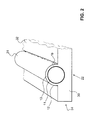
- Fig. 1 shows a schematic view of a collector element according to the invention.
- the collector element according to Fig. 1 comprises at least one, advantageously a plurality of parallel arranged absorber elements, in particular solar collector tubes 1 and a holder 2, which receives the solar collector tubes 1.
- the solar collector tubes 1 are preferably vacuum tubes 1, but other tubes are also conceivable.
- the term vacuum tubes therefore includes all solar collector tubes with absorber layers or absorber elements.
- the vacuum tube 1 comprises an inner tube 11 and an outer tube 12. Between the inner tube 11 and the outer tube 12, a gap 13 is formed, which is evacuated. Preferably, the internal pressure of the vacuum is less than 10 Pascal, in particular less than 0.1 Pascal. An absorber layer 10 for absorbing the heat of sunlight is arranged in this intermediate space 13, ie in a vacuum.
- the outer diameter of the vacuum tubes 1 is referred to as diameter D.
- the inner tube 11 consists of a good heat-conducting material. In particular, it may be a metal tube.
- the outer tube 12 is transparent in its direction of incidence of the solar radiation rectified side, ie substantially in the area 1 b. On the opposite side, the outer tube may be opaque.
- the vacuum tubes 1 of the collector element according to the invention are received by the holder 2 in such a way that the vacuum tubes come to lie next to one another.
- the vacuum tubes 1 are arranged at a distance A laterally spaced from each other.
- the vacuum tubes are parallel to each other.
- the vacuum tubes are preferably received over their entire length by the holder 2.
- the holder 2 is designed substantially as a cuboid and comprises a top 21, a bottom 22 and a plurality, here four, side walls 24.
- the side walls 24 connect the top 21 with the bottom 22.
- the holder 2 is made of a transparent, transparent or translucent Material. That is, sunlight incident on the holder 2 is guided inside the holder 2 due to its transparency.
- the translucent material of the holder 2 preferably has a refractive index n between 1.05 and 1.5.
- the bottom 22 may take a different shape than a flat shape.
- the bottom 22 is concave, convex, or parabolic, configured.
- the upper side 21 may, regardless of the configuration of the underside 22, over the entire width or only one entrance surface 25, also be configured concave or convex.
- the holder 2 made of Plexiglas or glass. These materials proved to be particularly robust against weather-related influences.
- materials are used which direct sunlight with a light transmission value (for example, according to ISO 13468-1 or DIN 5036-3) of more than 90%, in particular 92% or 93%, and are preferably temperature-resistant.
- the technology or the material of a fluorescence collector can be used.
- molecules may be embedded in the holder that fluoresce when exposed to sunlight, whereby, by total reflection, a large part of the incident light rays is conducted to the lower absorber layer surfaces where the light rays arrive concentrated. The efficiency is improved, especially in low-radiation environments.
- the grooves 20 extend from the top 21 into the holder 2 inside.
- the holder 2 preferably has a number of grooves 20 equal to the number of vacuum tubes 1.
- Each groove 20 is thus associated with a vacuum tube 1.
- the grooves 20 in the groove axis have a cross-section of the vacuum tube 1 complementary cross section, so that the vacuum tubes 1 can be inserted or embedded in the grooves 20. That is, in the present embodiment, that the grooves in cross section have the shape of circle segments. Circular segments which extend over an angle of 180 °, ie semicircular, or smaller than 180 °, are particularly advantageous.
- the process of replacement is very advantageous to the user, because it can replace defective vacuum tubes in a simple manner.
- the groove 20 has a length corresponding to the effective length of the vacuum tube.
- An effective length is understood to mean the length over which the absorption layer extends in the solar collector tube.
- the grooves 20 can be made into the holder 2 with high accuracy by a milling method.
- the surface of the groove 20 may be machined by grinding, polishing or lapping so that the surface of the groove 20 has a finer surface texture.
- This manufacturing method has the advantage that the vacuum tubes 1 can be inserted parallel to one another in the collector element with a high degree of accuracy. Alternatively, a plastic injection molding process can be used. This method also offers a high degree of accuracy.
- Fig. 3 the vacuum tubes 1 are shown with the same diameter D.
- the vacuum tubes 1 may also have different diameters D, wherein the groove 20 is adjusted according to the diameter D of the vacuum tube 1.
- the cuboid holder 2 upwardly delimiting area between the individual grooves is referred to as the entry surface 25.
- the entry surface 25 Via this entrance surface 25, rays S1, S2, S3 of the sunlight can enter the holder 2.
- the entry surface 25 may be planar, concave, as indicated by the entry surface 25 ', or convex.
- a flat entrance surface 25 is particularly advantageous, because this allows a particularly simple cleaning of the entry surface 25 and the part of the vacuum tubes 1, which protrudes beyond the entry surface 25.
- the entry surface 25 is preferably coated with a layer which is permeable to light rays in a first direction, so that therefore sunlight can enter the holder 2.
- a layer can be provided for example by suitable nanotechnology.
- the reflection of the rays S3 on the inside 25 of the holder 2 can then be increased. In other words, the reflection on the inside is greater than the size of the normally existing ones Rayleigh reflection can be increased.
- Nanoscale Laminated Layers is disclosed in Applied Physics Newsletter Volume 80, Number 14 .
- the groove 20 may be referred to as U-shaped. That is, the groove 20 has in a first section left and right on a flat side wall. In a second section, the side wall then turns into a semicircular shape. Accordingly, the second section begins from the bottom of the groove as seen at the height at which the center of the inserted vacuum tube comes to rest.
- the flat side wall can also be configured as a curved side wall. Further alternatives are also conceivable, provided that the first section does not narrow the cross section of the groove 20.
- the groove 20 thus has in the first section to a width which is equal to or greater than that Diameter of the vacuum tube 1, so that it can be inserted from above into the groove 20.
- the first portions can also extend at an angle, so that the shading of the vacuum tube 1 can be minimized.
- the grooves 20 are laterally spaced from each other.
- the distance is specified as distance A.
- the distance A is in particular smaller than the diameter D.
- the distance between the vacuum tubes can be chosen to be comparatively small, which means that the efficiency is greater compared to devices of the prior art.
- the holder 2 allows the arrangement of a larger number of vacuum tubes on the same collector surface. For vacuum tubes with a diameter of 38 mm, the distance A is therefore between 22.8 mm and 34.2 mm.
- a holder according to the invention has 13 to 16 grooves 20 over a width of one meter relative to a tube diameter of 38 mm.
- the reflector 3 which is equipped with a reflective layer, arranged.
- the reflective layer may also be referred to as a mirror layer become.
- the reflector 3 is used for reflection of the sunlight, which has entered the holder 2. By this reflection, it is possible to irradiate the lower part 1a of the vacuum tube 1 with sunlight. The lower part 1a is thus indirectly supplied with the sunlight.
- a second embodiment is shown.
- Like reference numerals designate the same or similar features in all figures.
- the outer tube 12 and the holder 2 form a single element, the housing 30th Then the holder 2 is off Fig. 1 no solid material element, but a, for example, cuboid forms the bottom part of the housing 32.
- the reference numeral 31, the tubular part of the housing is designated.
- the inner tube 11 is disposed within an evacuated housing 30 from.
- the absorber layer 10 is protected in this evaluated space 13.
- the absorber layer 10 is arranged around the entire tube in cross section over a substantial portion of the length of the tube.
- the top of the outer tube 12 may be configured even with the housing 30. It is essential that the heat-transferring fluid is disposed within the inner tube 11.
- the insertion of a further tube 300 can also be considered here Fig. 5 be turned off.
- This embodiment also belongs to the combination of the invention.
- the reflector 3 may be disposed directly on the underside 22 of the holder 2 or the housing 30.
- the reflector 3 is preferably an aluminum sheet with an anodized coating. Such an aluminum sheet may be adhered or otherwise secured to the underside 22 of the holder. Alternatively, the aluminum sheet can also be poured or embedded in the holder 2.
- the provision of the reflector within the housing 30 after Fig. 2 also protects the reflector. It is also possible, the lower part of the housing 30 opaque, preferably as a reflector, form and only the upper portion transparent.
- the reflector 3 may also be a mirror layer, which is applied directly to the underside 22 of the holder 2 by a vapor deposition method. Accordingly, the reflector 3 is a thin layer on the underside 22 of the holder 2.
- a vapor deposition method proves to be particularly advantageous because the coating can be applied in concave or convex or parabolic or planar configurations of the bottom 22 in an efficient manner.
- the reflective layer on a carrier, not shown.
- the carrier and the reflective layer are referred to as a reflector.
- This carrier is embedded or cast in the lower part of the holder 2. This means in this case that the carrier with the reflector layer is completely absorbed by the holder. In other words, the reflector is completely surrounded by the holder 2 here.
- the described attachment of a reflector layer has the advantage that the reflector layer 3 is protected by the holder 2 from the weather conditions described in the introduction.
- the reflector layer can thus retain a lasting surface quality over the life of the collector element.
- the side walls 24 are also provided with a reflective layer, preferably analogously to the underside 22. Accordingly, rays which impinge on the side walls 24 from the interior of the holder 2 are reflected on the side walls 24. The Rays that have entered the holder 2, so can not escape through the side walls 24.
- the side walls 24 with solar cells or photovoltaic cells, wherein the reflector layer is replaced with these cells at least partially or completely. With the solar cells electrical energy can then be provided, which supply, for example, the circulation pump for the heat transfer medium and / or the control electronics.
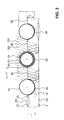
- Fig. 4 are three side by side in the holder 2 lying vacuum tubes 1 shown in a sectional view. Also here the incident sunlight is shown as rays S1, S2 and S3.
- the rays S1 indicate the upper part 1b of the vacuum tube 1.
- the beam S2 enters the holder 2 through the entrance surface 25 and is reflected at the reflector layer 3, thus indirectly illuminating the lower part 1a of the vacuum tube.
- the beam S3 enters the holder 2 through the entry surface 25 and is reflected at the reflector layer 3. In the course of the beam S3 is then reflected again on the inside at the entrance surface. By a further reflection on the reflector layer 3, the beam can then reach the lower part 1a of the vacuum tube 1 indirectly.
- the vacuum tubes 1 are not irradiated by a specific sector here, as is the case with a reflector of the prior art. If the sun is shallow, it may be that the vacuum tube indirectly from below via an entrance surface 25, which is not directly adjacent to the corresponding vacuum tube is irradiated. Thus, in low sunshine, a greater proportion of the beams can be used, as in collector systems of the prior art. The efficiency is therefore increased.
- the holder 2 may be filled with a preferably colorless medium, such as a fluid, a gas or a vacuum.
- a preferably colorless medium such as a fluid, a gas or a vacuum.
- the grooves 20, the top 21, the bottom 22 and the side walls 24 form a kind of shell or hollow body, which can absorb the fluid, the gas or the vacuum.
- the medium is a fluid, it must be chosen so that it does not freeze in winter and damage the shell.
- Such fluids are known in the art.
- water is used with ethylene glycol, water with hexanol, or other ethanols.
- the fluid may also be a synthetically produced oil.
- the reflection layer can be mounted both on the outside and on the cavity or interior facing surface.
- the holder 2 may also be designed as a shell.
- the top 21 of the holder 2 has in this embodiment a rectangular opening and the corresponding side walls 24 have a semicircular opening, so that forms a kind of open groove.
- the vacuum tube 1 can then be inserted into this open groove and connected by means of an adhesive with the side edges.
- the adhesive takes over the sealing effect at the same time.
- the bottom 22 and optionally the side walls 24 may be made of a metallic material, for example a deep-drawn or stamped metal sheet.
- the top 21 is here from one of the above Materials.
- the bottom 22 and sidewalls 24 form a type of pan which can receive the fluid, gas or vacuum.
- the tub With the lid, the tub can be completed and thus a hollow body is provided.
- the surface of the side walls 24 and the bottom 22, which face the interior of the hollow body, may be polished or provided with the reflection layer. By arranging the reflection layer on the side facing the interior, this is well protected against the effects of weather.
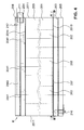
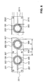
- Fig. 4 and 5 show a collector element according to the invention K according to a further embodiment of the invention, as shown Fig. 5 visible at least one absorber element 100 and a holder 200 includes. Furthermore, the collector element advantageously comprises a heat storage element 300 assigned to each absorber element 100.
- the holder 200 preferably comprises a holder body 201, which may also be referred to as a light guide body due to its light-conducting property.
- the holder body 201 preferably has the shape of a cuboid and thus has according to Fig. 6 a bottom 2010, two side surfaces 2011, a top 2012, a bottom front side 2013 and a top front side 2014 on. Sunlight can enter the holding body 201 via the upper side 2012.
- the collector element K or the holder body 201 has at least two cylindrical openings 202.
- the openings 202 extend, preferably parallel to one another, from the lower end face 2013 to the upper end face 2014 through the holder body 201.
- the cylindrical openings 202 serve to receive one absorber element 100 each.
- the holder body 201 is made of a transparent or translucent material, such as Plexiglas, Glass or other suitable materials which guide the sunlight with a transmittance of over 90% and are preferably temperature resistant.
- the holder body 201 may be filled with a fluid or gas, wherein the boundary surfaces of the holder body 201 form a hollow body.
- the underside 2010 as well as the two short side surfaces 2011 and the lower end side 2013 as well as the upper end side 2014 of the holder body 201 are preferably provided with a reflection layer or mirror layer.
- This reflection layer serves to reflect the incident sunlight.
- the reflection layer can be applied for example by a vapor deposition method. If the holder body 201 is formed as a hollow body, the reflection layer or the mirror layer can be arranged both on the outside and on the inside, which faces the inside of the cavity.
- a vapor-deposited coating has the advantage that the configuration of the lower surface 2010 may be flat, convex, concave or parabolic. A tedious deformation of any reflector sheets, as is the case with collector elements from the state, is omitted in this holding body.
- the mirror layer may have a suitable rough surface in order to allow diffuse scattering of the incident solar rays. It is also very small spherical particles in the edge zones of the light guide body in the immediate vicinity of the mirror layer surfaces are introduced, so that a Rayleigh scattering / reflection. The just described Treatment of the reflection layers allows more effective irradiation of the rear surfaces of the absorber elements 100.
- the coating can also be designed as a polished sheet metal.
- the mirror layers or reflection layers also prevent long-term moisture absorption by the material.
- the light entrance surface 2012 can be treated and sealed on the basis of chemical nanotechnology, so that the adhesion of dirt and foreign substances is virtually prevented and also in the long run, the beading of water is ensured.
- a first inner profile element 203 and on the upper end side 2014 a second inner profile element 204 is arranged.
- the inner profile elements 203, 204 preferably extend over the entire surface of the end faces 2013, 2014.
- a first outer profile element 205 and on the second inner profile element 204 a second outer profile element 206 is arranged.
- the inner and outer profile elements 203, 204, 205, 206 are connected to each other and to the holder body 201 by means of a screw connection.
- the profile elements 203, 204, 205, 206 are made of a plastic, such as PMMA or PEEK, or a metal, such as aluminum.
- the lower end side 2013 of the holder body 201 has a groove 207 which extends from the end face 2013 into the holder body 201 extends into it. Further, the groove 207 is arranged such that the groove 207 connects all cylindrical openings 202 with each other. Preferably, the groove 207 is configured in its cross section as a semicircular. Other cross-sectional shapes, such as rectangular or square, are also conceivable.
- the groove 207 preferably extends into the front side 2013 only over a small depth. The depth of the groove 207 is chosen so that the air can be removed as easily and efficiently from the cavity in the production of the vacuum.
- a seal is preferably arranged between the lower end face 2013 and the first inner profile element 203, and between the upper end face 2014 and the second inner profile element 204.
- the seal can be achieved, for example, by a coating of the end faces 2013, 2014.
- an elastic seal in corresponding wells, not shown, can be embedded. Due to the evacuation of cavities described below, which are limited inter alia by the profile elements, a particularly durable design of the seal is necessary.
- a modified inventive collector element is shown in a view from the front.
- the cylindrical openings 202 have a diameter D and are laterally spaced from each other.
- the distance is specified as distance A.
- the distance A is in particular smaller than the diameter D of the cylindrical opening 202.
- the distance between the cylindrical openings 202 can be chosen to be comparatively small, which means that the efficiency is greater compared to devices of the prior art.
- the holder body 201 allows the arrangement of a larger number of cylindrical openings on the same collector surface. For cylindrical openings with a diameter of 38 mm, the distance A is therefore between 22.8 mm and 34.2 mm.
- a holder 200 according to the invention has 13 to 16 cylindrical openings 202 over a width of one meter.
- the cylindrical openings are preferably arranged centrally or centrally.
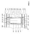
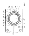
- Fig. 7 shows a part of the Fig. 6 wherein the arrangement of the absorber element 100 in the holder body 201 and the heat storage element 300 in the absorber element 100 is shown by way of example. A plan view of the arrangement is shown in FIG Fig. 5 shown.
- the cylindrical opening 202 is delimited by a hollow cylindrical jacket surface 2020.
- the absorber element 100 is here arranged concentrically in the cylindrical opening 202 by means of means described below. An eccentric arrangement is also possible.
- the absorber element 100 or the length of the absorber layer has substantially the same length as the cylindrical opening 202.
- the absorber element 100 may also be configured shorter or longer than the cylindrical opening 202.
- the absorber element 100 preferably comprises an absorber layer 101 and the absorber tube 102.
- the absorber layer 101 is arranged on the outside of the absorber tube 102.
- the absorber element 100 has a maximum outer diameter which is smaller than the diameter D of the cylindrical opening 202.
- an annular gap 208 is created between the lateral surface 2020 of the cylindrical opening 202 and the absorber layer 101.
- the annular gap 208 forms part of the resulting cavity 209, which is bounded below by the first inner profile element 203 and at the top by the second inner profile element 204. This cavity 209 can be evacuated.
- the absorber tube 102 is preferably made of a good heat-conducting material, such as a metallic material. Especially suitable is copper, aluminum, brass or stainless steel.
- the absorber layer 101 can for example be vapor-deposited on the absorber tube 102 or pressed on as a thin film.
- the absorber layer 101 is made of tin oxide (titanium oxide), metal carbide, black chrome, or black paint. Since the absorber layer 101 is in a vacuum, it is protected from any wear. In addition, occur due to the vacuum virtually no heat loss to the environment.
- the absorber layer may also be selectively coated.
- Such selective coatings have the advantage that the heat losses can be reduced by thermal radiation.
- Such selective coatings are known to the person skilled in the art.
- the absorber element 100 is mounted in an annular groove 2030 in the first inner profile element 203 and in an annular groove 2040 in the second inner profile element 204.
- the annular grooves 2030, 2040 are wetted prior to insertion of the absorber element 100 with a permanently elastic silicone adhesive or with a silicone sealant.
- the inner profile elements 203, 204 define the cavity 209 to be evacuated.
- the cavity 209 to be evacuated consists essentially of the cavity which arises through the annular gap 208 and the grooves 207.
- the internal pressure of the vacuum is less than 0.1 pascal.
- the vacuum space can also from the entire housing 30 from Fig. 2 consist.
- Essential is only the sequence (upwardly transparent) vacuum housing 11, vacuum space 13, absorber layer 101 on thermally conductive tube 100 with internal fluid path, which may still have an inner tube 300 with optional latent memory 301.
- the collector element has an evacuation port 210 which, for example, in FIG Fig. 3 is apparent.
- the evacuation port is connected to the cylindrical openings 202 via the groove 207. That is, via the evacuation port 210, the air, which is located in annular gaps 208 and in the groove 207, can be removed.
- the evacuation port 210 is closed with a suitable shut-off valve.
- the heat storage element 300 can be seen.
- the heat storage element 300 is preferably a hollow body which can be filled with a heat storage medium and has a cavity 301.
- the hollow body is essentially cylindrical. Accordingly, the hollow body comprises a tubular hollow body side wall 303 and two hollow body cover 302, which are arranged on the front side of the hollow body wall 303.
- the outer diameter of the heat storage element 300 is selected to be smaller than the inner diameter of the absorber tube 102.
- the heat storage element 300 is mounted concentrically in the absorber tube 102 with centering cams 400.
- the centering cams 400 are preferably welded to the absorber tube 102 or to the hollow body side wall 303 and configured such that the heat storage element 300 can be held by a holding force resulting from a static friction force.
- three centering cams 400 per bearing point are arranged at an angle of 120 °. Over the entire length of the heat storage element 300 several such bearings are arranged.
- the concentric mounting of the heat storage element 300 in the absorber tube 102 creates an annular gap-shaped intermediate space 103.
- This intermediate space 103 can be flowed through by a heat transfer medium.
- a heat transfer medium In particular, so that the heat transfer amount can be concentrated on a near-absorbent area, namely an annular gap.
- Within the heat storage tube 300 may be air, it may be a latent storage material or - somewhat less favorable - vacuum or other substance.
- the advantage of this medium in space 301 is its isolation via the heat transfer medium in space 103. This medium in 301 is not in contact with "cold" elements, but is in easily accessible equilibrium with the amount of heat absorbed by the absorber.
- the cavity 301 of the heat storage element 300 which may also be called a latent heat store, is filled up with a phase change material or a phase change material.
- a phase change material for example, microencapsulated paraffin or microencapsulated paraffin beads are suitable. These waxy materials can store heat reversibly.
- the absorber elements 100 absorb solar energy, ie heat
- the heat is transferred to the heat transfer medium which flows in the intermediate space 103.
- heat is also partially transferred to the heat storage element 300, wherein the phase change material also heats up.
- the phase change material changes its state and liquefies. In other words, this means that part of the heat energy present by the solar radiation is absorbed by the heat transfer medium and another part by the phase change material.
- the heat energy is stored by the phase change material and can be delivered at a time in which the solar radiation decreases or no longer exists. This can be the case, for example, during a change in the weather or at night.
- the phase change material solidifies.
- the phase change material has a melting point which is between 20 ° C and 90 ° C.
- the geographic location is crucial for the choice of the melting point.
- a phase change material with a higher melting point is used than for layers with lower average temperatures.
- Other requirements criteria, such as the operating temperature of the heat transfer medium also influence the choice of the phase change material.
- the melting point temperature is slightly greater, for example 3 ° C to 10 ° C, than the optimum operating temperature.
- the inner profile elements 203, 204 each have a through opening 2031, 2041 on.
- the outer profile elements 205, 206 each have a channel 2050, 2060.
- the cold heat transfer medium may for example result from a heat exchanger and is represented by the arrows 401.
- the cold heat transfer medium 401 thus enters through the channel 2050 via the opening 2031 in the gap 103 a.
- the heat transfer medium 401 can absorb heat, which is provided by the absorber element 100 and by the heat storage element 300.
- the warm heat transfer medium 402 leaves the gap 103 via the opening 2041 and can be directed into the channel 2060. Via a connection element 211, like this one in FIG Fig. 3 is shown, the warm heat transfer medium may for example be supplied to a heat exchanger.
- the surfaces can, for example, be provided with a metallic coating be provided. Thereby, a passage of water vapor can be reliably prevented.
- a temperature sensor 212 which can measure the temperature of the heat transfer medium.
- the output temperature of the heat transfer fluid can be monitored.
- This variable can be used as a control variable, so that a protective tarpaulin 505 can be pulled over the top of the collector, for example in the event of failure of the circulation pump for the heat transfer medium, for example water, so that no further significant heat input occurs.
- the tarpaulin is opaque and has an insulating effect.
- a buffer battery can be provided for the drive so that it can still control this movement even in the event of a power failure.
- the latent storage is a good preventive measure against overheating of the system. Furthermore, excess energy can be delivered to peripheral devices such as a heater, etc. Furthermore, a protective device may be provided, which by means of Fig. 9 to 11 is described.
- the coaxial arrangement of the absorber tube 102 and the heat storage element 300 in the cylindrical aperture 202 allows for optimal design of the gap 103 by the flexible selection of different diameters of the coaxially arranged tubes for the most efficient implementation of solar energy.
- the heat transfer medium flows through the intermediate space 103 in a turbulent flow
- the heat exchange between the absorber pipe 102 and the heat transfer fluid can take place in a particularly efficient manner.
- the turbulent flow can, for example be achieved by the arrangement of the centering cam 400. Alternatively, mixing elements can also be provided.
- Fig. 8 the beam path of sunlight is shown, which is incident in the cuboid holder body 201 over the top 2012.
- the top 2012 can also be referred to as entrance area. Via this entrance surface 2012, rays S100, S200, S300 of the sunlight can enter the holder body 201.
- the entrance surface 2012 may be flat, concave or convex. A flat entrance surface 2012 is particularly advantageous because this allows a particularly simple cleaning of the entrance surface 2012.
- the entrance surface 2012 is preferably coated with a layer which is permeable to light rays in a first direction, so that therefore sunlight can enter the holder body 201.
- the entrance surface 2012 may be provided with a nano-coating described above with the aid of the first embodiment. All of the embodiments disclosed in this description can be connected or combined as desired either completely or only partially.
- the rays S100 indicate the upper part 100b absorber element 100th
- the beams S200 enter the holder body 201 through the entrance surface 2012, and are reflected on the reflector layer disposed on the lower side 2010, thus indirectly exposing the lower portion 100a of the absorber element 100.
- the beam S300 enters the holder body 201 through the entrance surface 2012 and is reflected on the reflector layer disposed on the lower side 2010. In the further course of the beam S300 is then reflected on the inside at the entrance surface 2012 again. As a result of the renewed reflection on the inside of the entrance surface 2012, the beam S300 illuminates the absorber element 100 from above.
- the absorber elements 100 are not irradiated by a specific sector here, as is the case with a reflector of the prior art. If the sun is shallow, it may be that the vacuum tube is indirectly irradiated from below via an entrance surface 2012, which is not directly in the region of the corresponding absorber element 100. Thus, in low sunshine, a greater proportion of the beams can be used, as in collector systems of the prior art. The efficiency is therefore increased.
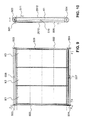
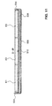
- Figs. 9 to 11 show an arrangement of a plurality of collector elements K1, K2, K3 with a cover device 500.
- the collector elements K are preferably configured as described above.
- Such a cover device 500 prevents damage to a collector element K or to an arrangement of a plurality of collector elements K1-K3 according to the invention. Damage can be caused, for example, by weather events such as hail, storm, snow, etc., overheating if the heat consumption of a heat exchanger connected to the collector element is too low or due to power failure (threatening) or.
- the cover device 500 comprises a drive device 501, a drive belt 502, driven pulleys 503, deflection pulleys 504 and a protective cover 505, which may also be referred to as protective tarpaulins.
- the protection panel 505 is disposed parallel to the surface of the collector elements and extends over the entire surface of the collector elements K1, K2, K3 if the surface of the collector elements is to be covered by the protection panel 505.
- the protective cover 505 is configured as a circumferential protective cover, that is to say the protective cover moves downwards on the upper side 2012 and upwards again on the underside of the cover.
- the protection panel 505 may also be driven in two directions.
- the protective cover 505 is disposed below or behind the collector elements K1, K2 and K3, ie on the bottom side 2010, if they are to absorb heat.
- the protective tarpaulin 505 has a length in the direction of flow, which corresponds to the distance between the two deflection / pulleys 503 and 504, so that it is either stretched on top of 2012 protective before the collector or - for example, for drying - behind the bottom 2010 is stretched behind the collector.
- the protective cover 505 can be stretched by the lateral guides or by clamping a transverse web, with which the flexible tarpaulin is pulled along.
- the driven pulleys 503 are above the collector element assembly and the diverting pulleys 504 are disposed below the collector element assembly.
- two pulleys 503 and two guide pulleys 504 are arranged.
- the two pulleys 503 and the two deflection pulleys 504 can be connected via common axes.
- the drive belt 502 is driven by the driven pulley 503 and deflected by the deflection pulley 504.
- the protective panel 505 is connected to the drive belt 502 and can be driven by it. As soon as the drive device 501 receives a corresponding control command, the drive belt 502 or the protective cover 505 is driven via the drive pulley 503. Thereby, the protection panel 505 can be moved up or down.
- the protective cover 505 may have cleaning bristles 506.
- This cleaning bristles 506 slide on a movement of the protective cover 505 over the surface of the individual collector elements and thus clean the surfaces.
- Such cleaning bristles 506 are particularly advantageous in the removal of dust, dirt particles, snow, etc.
- various sensors can be arranged. These sensors detect actual conditions of the environment. As soon as an actual state reaches or exceeds a predetermined desired state, the process of covering or uncovering the collector elements can be triggered.
- the corresponding desired states can be stored, for example, in a solar controller.
- a Photosensor 509 measures the brightness of the radiation on the collector elements.
- a hail sensor 510 detects emerging hailstorm.
- the values measured by the sensor are compared with predetermined reference values.
- the drive device 501 is supplied with the corresponding command and the protective plate 505 is pulled over the collector elements K1 to K3.
- the drive system receives the command to retract the protective cover so that the collector elements K1 to K3 can again absorb the solar energy.
- Another sensor may be, for example, a snow sensor.
- the differently constructed snow sensors 507 and 508 first register readings by relative darkening of their cell surfaces, which are compared with the readings from the photosensor 509 along with stored and predetermined reference values.
- the reflections of the built-in light emitting diodes (LED) in the snow sensors are evaluated. If then the electronic evaluation in the solar controller the initial snowfall then the bristles 506 mounted on the back of the guard are once wiped off the entire surface of the collector elements.
- the amount of snow wiped off the surface is deposited on one of the two snow sensors, which is decisive for the evaluation.
- the measured values are buffered.
- the protective cover can cover the surface of the collector elements. If only a small amount of snow is detected, the wiping operations can be repeated several times.
- the protective cover 505 After sunrise, depending on the month, orientation and inclination of the collector elements, a certain amount of time passes until the snow sensors register the solar beams and then output the corresponding signal to the drive device 501 so that the protective cover 505 can be removed from the surface of the collector elements.
- the guard panel 505 then moves down intermittently to allow the overlying snow masses to slide off. If the protection panel 505 has a nano-coated surface, the snow masses can slide off particularly well.
- the solar controller can measure the load current of the electric motor.
- the load current can be considered as an indirect indicator of the snow load or the thickness of the snow layer.
- the electric motor is accelerated jerkily and stopped after a short time and is then accelerated again jerkily until the load current drops to ever smaller values and finally the normal load current without snow load from the solar controller is detected as an indirect indicator of snow clearance.
- This movement allows a better sliding of the snow masses of the protection panel 505 down to the roof surface without in To make this area an obstructive ever higher pile, because here, too, the sliding snow masses are repelled one behind the other.
- the solar controller is programmed so that the top collector element is controlled first and the lowest collector element last. This means that the topmost collector element is first cleared of snow.
- the protective panel 505 is again positioned below the collector members in the original position by means of magnetic sensors and distance-measurement induction strips mounted between the inside of the drive pulley 503 and the motor flange.
- the protective device reliably prevents damage to the collector elements described above and protects the collectors from hail damage, prevents snow covers on collectors; Furthermore, a self-cleaning is possible in the event of contamination.
- the protection device may be provided with a backup battery, not shown, which ensures an emergency power operation in case of power failure.
- the collector elements are covered, for example, after 30 seconds, if a minimum brightness in the daytime mode is measured by means of the photosensor.
- the back-up battery of the emergency power supply reaches a critical range of undervoltage (eg 11.7 or 23.4 V DC).
- a critical range of undervoltage eg 11.7 or 23.4 V DC
- the field module is covered with the protective cover after one hour, for example.
- the audible and visual warning signals are only switched off with an acknowledgment.
- the controller In solar operation, the controller (boiler room) constantly compares the differential temperature ⁇ t between the collector temperature and the storage tank temperature of the latent storage tank. If, over a certain period of time, it tends to increase too fast and is above the fixed reference value, the field module is covered with the protective field until the further measured ⁇ t values return to their normal range.
- the guides can be formed by the pulleys and pulleys 503/504, because if they are driven directly and the tarpaulin 505 is braced over this, this direct drive over the length of the solar element is possible if the circle running through corresponding outside of the solar panels Ribbons is closed. It is also possible to provide lateral guides, which then integrate according to the drive belt 502 on which the tarpaulis is laterally attached or at least guided. It may be that at one or more specific points of these belts have these at opposite locations on transverse drive bars, which are attached to this, to which corresponding sections of the tarpaulin 505 are firmly connected.
- a tension-resistant tear-resistant tarpaulin can be moved as a cover and protection against the solar panels and on the other hand, this tarpaulin is stowed behind the solar panels.
- tarpaulin materials can be used, as they are used in truck tarpaulins or tents.
Landscapes
- Engineering & Computer Science (AREA)
- Physics & Mathematics (AREA)
- Life Sciences & Earth Sciences (AREA)
- Sustainable Development (AREA)
- Sustainable Energy (AREA)
- Thermal Sciences (AREA)
- Chemical & Material Sciences (AREA)
- Combustion & Propulsion (AREA)
- Mechanical Engineering (AREA)
- General Engineering & Computer Science (AREA)
- Roof Covering Using Slabs Or Stiff Sheets (AREA)
- Optical Elements Other Than Lenses (AREA)
Abstract
Description
Die vorliegende Erfindung betrifft ein Kollektorelement zur Wärmegewinnung aus der Sonnenstrahlung gemäss den Merkmalen des Oberbegriffs des Anspruchs 1. Ferner betrifft sie eine Schutzabdeckung für ein Kollektorelement zur Wärmegewinnung aus Sonnenstrahlung gemäss den Merkmalen des Anspruchs 7.The present invention relates to a collector element for heat recovery from solar radiation according to the features of the preamble of claim 1. Furthermore, it relates to a protective cover for a collector element for heat recovery from solar radiation according to the features of claim 7.
Kollektorelemente zur Wärmegewinnung aus der Sonnenstrahlung sind aus dem Stand der Technik bekannt. Beispielsweise werden solche Kollektorelemente als CPC-Kollektoren (Compound Parabolic Concentrator Kollektor) bezeichnet.Collector elements for heat recovery from solar radiation are known from the prior art. For example, such collector elements are referred to as CPC collectors (Compound Parabolic Concentrator Collector).
CPC-Kollektoren umfassen typischerweise mehrere Vakuumröhren zur Absorption der durch das Sonnenlicht bereitgestellten Wärme. Die Vakuumröhren sind typischerweise parallel und beabstandet zueinander in einem Halter angeordnet. Der Halter umgibt die Vakuumröhren üblicherweise am oberen und am unteren Ende. Das heisst, der grösste Teil der Vakuumröhre steht nicht mit dem Halter in Berührung. Die Vakuumröhren werden dabei von einer zur Sonne gerichteten oberen Seite direkt mit Sonnenlicht bestrahlt. Durch das Anordnen eines Reflektors zwischen Halter und Vakuumröhren können die Vakuumröhren auch von der zur Sonne abgewandten hinteren Seite bestrahlt werden. Hierbei kann das Sonnenlicht durch die Lücke zwischen den einzelnen Vakuumröhren auf den Reflektor gelangen und wird von diesem dann auf die untere Seite der Vakuumröhre reflektiert. Der Wirkungsgrad eines Sonnenkollektors kann durch das Anordnen eines solchen Reflektors erhöht werden.CPC collectors typically include multiple vacuum tubes for absorbing the heat provided by sunlight. The vacuum tubes are typically arranged parallel and spaced apart in a holder. The holder usually surrounds the vacuum tubes at the top and at the bottom. This means that most of the vacuum tube is not in contact with the holder. The vacuum tubes are directly exposed to sunlight from an upper side facing the sun. By arranging a reflector between the holder and vacuum tubes, the vacuum tubes can also be irradiated from the rear side facing away from the sun. Here, the sunlight can pass through the gap between the individual vacuum tubes on the reflector and is then reflected by this on the lower side of the vacuum tube. The efficiency of a solar collector can be increased by arranging such a reflector.
Im Querschnitt betrachtet weisen Reflektoren des Standes der Technik die Struktur von mehreren aneinander angrenzenden Parabeln, Halbkreisen oder anderen Kurvensegmenten auf. Dabei entsteht eine wellenartige Struktur. Die Vakuumröhren sind dabei im wesentlichen symmetrisch zu den Wellenbäuchen der wellenartigen Struktur angeordnet.Viewed in cross-section, prior art reflectors have the structure of a plurality of adjacent parabolas, semicircles, or other curve segments. This creates a wave-like structure. The vacuum tubes are arranged substantially symmetrically to the bellies of the wave-like structure.
Die
Die Wärmeübertragung und Funktionssicherheit ist jedoch in vielerlei Hinsicht zu verbessern.However, the heat transfer and reliability is to be improved in many ways.
Kollektorelemente zur Wärmegewinnung aus Sonnenstrahlung stehen funktionsgemäss zumeist im Freien, sind mit einer Oberfläche in einem vom Breitengrad der Aufstellung abhängenden Neigung zumeist Richtung Süden ausgerichtet und sind somit der Witterung ausgesetzt. Aus dem Stand der Technik sind verschiedene Massnahmen zum Schutz von solchen Kollektorelementen bekannt.Collector elements for heat recovery from solar radiation are functionally mostly outdoor, are aligned with a surface in a dependent of the latitude of the formation tendency mostly south and are therefore exposed to the weather. Various measures for the protection of such collector elements are known from the prior art.
Die
Mit einem solchen Schutzsystem ist es möglich, den für Hagelschlag anfälligen Reflektor mechanisch zu schützen. Starker Hagelschlag deformiert den Reflektor und zerstört die Eloxalschicht auf dem Reflektor.With such a protection system, it is possible to mechanically protect the susceptible to hail impact reflector. Heavy hailstorm deforms the reflector and destroys the anodized layer on the reflector.
Bei der
Dem Fachmann ist zudem bekannt, dass sich Schmutz, wie Laub, Äste, etc. zwischen der Vakuumröhre und dem Reflektor festsetzen kann. Durch den Schmutz, welcher sich nur sehr mühsam entfernen lässt, wird der Wirkungsgrad eines Kollektorelementes negativ beeinflusst. Ferner wird durch den Schmutz und die sich darin ansammelnde Feuchtigkeit die Moosbildung auf dem Reflektor begünstigt.The skilled person is also aware that dirt, such as leaves, branches, etc. can set between the vacuum tube and the reflector. The dirt, which can be removed only with great difficulty, the efficiency of a collector element is adversely affected. Furthermore, the dirt and the moisture accumulating in it favors moss formation on the reflector.
Aus dem Stand der Technik ist mit der
Asche und Staub können sich ebenfalls leicht auf dem Reflektor festsetzen. Eine Reinigung des Reflektors könnte den Wirkungsgrad wieder auf ein ursprüngliches Niveau bringen. Allerdings ist die Reinigung sehr aufwendig, denn üblicherweise müssen, insbesondere bei nicht ebenen Sonnenkollektoren, die Vakuumröhren vom Halter demontiert werden, so dass der Benutzer Zugang zum Reflektor hat. Ansonsten ist die Reinigung nur zwischen den einzelnen Vakuumröhren möglich. Jedoch ist eine gute und zufrieden stellende Reinigung fast nicht möglich, weshalb immer mit Einbussen des Wirkungsgrades gerechnet werden muss.Ash and dust can also easily settle on the reflector. Cleaning the reflector could bring the efficiency back to an original level. However, the cleaning is very expensive, because usually, especially in non-planar solar panels, the vacuum tubes are disassembled from the holder, so that the user has access to the reflector. Otherwise, cleaning is only possible between the individual vacuum tubes. However, a good and satisfactory cleaning is almost impossible, so it must always be expected with losses of efficiency.
Die Reflektoren sind typischerweise aus Aluminiumblech hergestellt. Durch die Oxidation der Oberfläche des Aluminiumblechs wird das Reflexionsvermögen erheblich reduziert. Auch dies wirkt sich negativ auf den Wirkungsgrad aus.The reflectors are typically made of aluminum sheet. The oxidation of the surface of the aluminum sheet significantly reduces reflectivity. This also has a negative effect on the efficiency.
In Richtung der Vakuumröhren betrachtet, weisen die Reflektoren des Standes der Technik typischerweise eine zykloidennahe order kurvenartige Form auf. Pro Bogen kann eine Vakuumröhre angeordnet werden, das heisst, dass aufgrund der zykloidenartigen Ausgestaltung des Reflektors lassen sich zudem nur eine sehr begrenzte Anzahl von Vakuumröhren pro Längeneinheit, also in der Kollektorbreite, anordnen. Hinzu kommt noch, dass Reflektoren des Standes der Technik typischerweise Flächensegmente aufweisen, welche das einfallende Licht in nicht optimalen Winkeln reflektieren, so dass das reflektierte Licht nicht vollständig nutzbar ist. Dies resultiert ebenfalls in einem Verlust an Wirkungsgrad.Viewed in the direction of the vacuum tubes, the prior art reflectors typically have a cycloidal or curved shape. Per arc, a vacuum tube can be arranged, which means that due to the cycloid-like design of the reflector can also only a very limited number of vacuum tubes per unit length, ie in the collector width, arrange. In addition, prior art reflectors typically have surface segments which reflect the incident light at non-optimal angles, such that the reflected light is not fully usable. This also results in a loss of efficiency.
Aus der
Eine Schneeschutzvorrichtung für Solarkollektoren ist aus der
Ausgehend von diesem Stand der Technik liegt der Erfindung die Aufgabe zugrunde, ein Kollektorelement anzugeben, welches die Nachteile des Standes der Technik überwindet. Es soll bei verschiedensten Witterungsbedingungen einen möglichst hohen Wirkungsgrad aufweisen.Based on this prior art, the invention has for its object to provide a collector element which overcomes the disadvantages of the prior art. It should have the highest possible efficiency in various weather conditions.
Ferner hat die Erfindung die Aufgabe, eine Schutzabdeckung für Kollektorelemente zur Wärmegewinnung aus Sonnenstrahlung anzugeben, mit der ein technisch weniger aufwendiger Schutz als bei den Vorrichtungen aus dem Stand der Technik erreicht wird und weitere Nachteile des Standes der Technik überwindet. Insbesondere soll das erfindungsgemässe Kollektorelement robust gegenüber Umwelteinflüssen sein und einen möglichst hohen Wirkungsgrad aufweisen.Furthermore, the invention has the object to provide a protective cover for collector elements for heat recovery from solar radiation, with a technically less expensive protection than in the devices of the prior art is achieved and overcomes other disadvantages of the prior art. In particular, the inventive collector element should be robust against environmental influences and have the highest possible efficiency.
Die erstgenannte Aufgabe löst ein Kollektorelement mit den Merkmalen des Patentanspruchs 1. Ein Kollektorelement umfasst ein Absorberelement, insbesondere eine Solarkollektorröhre, insbesondere Vakuumröhre, welches ein Absorberrohr aus einem gut wärmeleitenden Material und eine Absorberschicht umfasst. Die Absorberschicht umgibt das Absorberrohr in wesentlichen Teilen, vorteilhafterweise vollständig. Um das Absorberrohr ist ein dies umgebendes und abschliessendes Gehäuseelement vorgesehen, so dass zwischen Absorberrohr und Gehäuseelement ein Vakuum, beispielsweise mit einem Druck von weniger als 10 Pascal, ausbildbar ist, wobei der Raum innerhalb der Innenwand des Absorberrohres mit einem Wärmeträgermedium durchströmbar ist. Bei einer bevorzugten Ausgestaltung kann der zumeist zylindrische Raum des Wärmeträgermediums auch mit einem Innenrohr versehen sein, so dass dort Latentspeichermaterial vorgesehen wird und das Wärmeträgermedium longitudinal in dem verbleibenden Ringspalt fliesst.The first object solves a collector element with the features of claim 1. A collector element comprises an absorber element, in particular a solar collector tube, in particular a vacuum tube, which comprises an absorber tube made of a good heat-conducting material and an absorber layer. The absorber layer surrounds the absorber tube in substantial parts, advantageously completely. To the absorber tube, a surrounding and final housing element is provided, so that between the absorber tube and the housing element, a vacuum, for example, with a pressure of less than 10 Pascal, can be formed, wherein the space within the inner wall of the absorber tube can be flowed through with a heat transfer medium. In a preferred embodiment, the mostly cylindrical space of the heat transfer medium may also be provided with an inner tube, so that there latent storage material is provided and the heat transfer medium flows longitudinally in the remaining annular gap.
Auch kann ein Kollektorelement mindestens zwei Absorberelemente, und einen Halter zur Aufnahme eines Absorberelementes mit einer Oberseite und einer Unterseite umfassen. Die Absorberelemente sind jeweils seitlich beabstandet zueinander im Halter angeordnet. Der Halter weist eine der Anzahl Absorberelemente gleiche Anzahl Rillen auf, welche in die Oberseite eingelassen sind und in welche die Absorberelemente einlegbar sind. Die Länge der Rillen entspricht im wesentlichen der wirksamen Länge der Absorberelemente.Also, a collector element may comprise at least two absorber elements, and a holder for receiving an absorber element having a top side and a bottom side. The absorber elements are each arranged laterally spaced from one another in the holder. The holder has a number of absorber elements equal number of grooves, which are embedded in the top and in which the absorber elements are inserted. The length of the grooves corresponds substantially to the effective length of the absorber elements.
Weiterhin ist die Erfindung durch eine Schutzabdeckung mit den Merkmalen des Patentanspruchs 7 gekennzeichnet.Furthermore, the invention is characterized by a protective cover having the features of claim 7.
Demgemäss umfasst eine Schutzabdeckung gemäss Anspruch 1 einen Antrieb, wobei der Antrieb mechanisch mit der Schutzabdeckung verbunden ist, so dass das oder die Kollektorelemente durch die Schutzabdeckung abdeckbar sind, welche eine flexible Schutzblache oder Schutzplane ist, die im wesentlichen der Grösse der abzudeckenden Kollektorelemente entspricht. Dabei sind Führungen vorgesehen, mit denen die Schutzplane über die Länge der Kollektorelemente oberhalb der Kollektorelemente aufziehbar ist, und es sind Führungen vorgesehen, mit denen die Schutzplane über die Länge der Kollektorelemente unterhalb der Kollektorelemente abdeckbar anordbar sind.Accordingly, a protective cover according to claim 1 comprises a drive, wherein the drive is mechanically connected to the protective cover, so that the one or more collector elements can be covered by the protective cover, which is a flexible protective cover or tarpaulin, which corresponds substantially to the size of the collector elements to be covered. Guides are provided with which the protective tarpaulin over the length of the collector elements above the collector elements can be pulled up, and there are guides provided with which the protective cover over the length of the collector elements below the collector elements can be arranged concealable.
Ein solches Kollektorelement ist insbesondere gegenüber Witterungseinflüssen besonders robust. Desweiteren kann ein Kollektorelement, welches mit einer erfindungsgemässen Abdeckung versehen ist, in einfacher Art und Weise gereinigt werden. Durch die einfache Reinigung, kann der Wirkungsgrad unter vielen Betriebsbedingungen gehalten werden.Such a collector element is particularly robust to weathering. Furthermore, a collector element, which is provided with a cover according to the invention, can be cleaned in a simple manner. Due to the easy cleaning, the efficiency can be reduced under many operating conditions being held.
Weitere vorteilhafte Ausführungsformen sind in den Unteransprüchen gekennzeichnet.Further advantageous embodiments are characterized in the subclaims.
Die Erfindung wird im folgenden anhand der Zeichnungen näher beschrieben. Es zeigen:
- Fig. 1
- eine perspektivische Ansicht eines erfindungsgemässen Kollektorelementes gemäss einem ersten Ausführungsbeispiel der vorliegenden Erfindung; welches zudem mit der Schutzabdeckung gemäss der vorliegenden Erfindung abgedeckt, gereinigt und geschützt werden kann;
- Fig. 2
- eine perspektivische Ansicht eines erfindungsgemässen Kollektorelementes gemäss einem zweiten Ausführungsbeispiel;
- Fig. 3
- eine Schnittansicht gemäss
Fig. 1 ; - Fig. 4
- eine Draufsicht einer Kollektorvorrichtung gemäss einem weiteren Ausführungsbeispiel der vorliegenden Erfindung;
- Fig. 5
- eine Detailansicht der Kollektorvorrichtung nach
Fig. 4 ; - Fig. 6
- eine Ansicht der Kollektorvorrichtung nach
Fig. 4 von vorne; - Fig. 7
- eine Detailansicht von
Fig. 6 ; - Fig. 8
- eine Schnittansicht von Teilen der
Fig. 4 ; - Fig. 9
- eine Draufsicht auf eine Anordnung von mehreren Kollektorelementen mit einer Schutzabdeckungsvorrichtung gemäss einem Ausführungsbeispiel der Erfindung für eine Kollektorvorrichtung;
- Fig. 10
- eine Schnittansicht gemäss Linie C-C' in
Fig. 9 einer Schutzabdeckungsvorrichtung gemäss der Erfindung; und - Fig. 11
- eine Schnittansicht gemäss Linie D-D' in
Fig. 9 einer modifizierten Schutzabdeckungsvorrichtung gemäss der Erfindung.
- Fig. 1
- a perspective view of a collector element according to the invention according to a first embodiment of the present invention; which can also be covered, cleaned and protected with the protective cover according to the present invention;
- Fig. 2
- a perspective view of a collector element according to the invention according to a second embodiment;
- Fig. 3
- a sectional view according to
Fig. 1 ; - Fig. 4
- a plan view of a collector device according to another embodiment of the present invention;
- Fig. 5
- a detailed view of the collector device according to
Fig. 4 ; - Fig. 6
- a view of the collector device according to
Fig. 4 from the front; - Fig. 7
- a detailed view of
Fig. 6 ; - Fig. 8
- a sectional view of parts of
Fig. 4 ; - Fig. 9
- a plan view of an arrangement of a plurality of collector elements with a protective cover device according to an embodiment of the invention for a collector device;
- Fig. 10
- a sectional view along the line CC 'in
Fig. 9 a protective covering device according to the invention; and - Fig. 11
- a sectional view along the line DD 'in
Fig. 9 one modified protective covering device according to the invention.
Die Vakuumröhre 1 umfasst ein Innenrohr 11 und ein Aussenrohr 12. Zwischen dem Innenrohr 11 und dem Aussenrohr 12 entsteht ein Zwischenraum 13, welcher evakuiert ist. Vorzugsweise ist der Innendruck des Vakuums kleiner als 10 Pascal, insbesondere kleiner als 0.1 Pascal. Eine Absorberschicht 10 zur Absorption der Wärme des Sonnenlichtes wird in diesem Zwischenraum 13, also im Vakuum, angeordnet. Der Aussendurchmesser der Vakuumröhren 1 wird als Durchmesser D bezeichnet. Das Innenrohr 11 besteht aus einem gut wärmeleitenden Material. Insbesondere kann es ein Metallrohr sein. Das Aussenrohr 12 ist in seiner der Einfallsrichtung der Sonnenstrahlung zugerichteten Seite, also im wesentlichen im Bereich 1b, durchsichtig. Auf der gegenüberliegenden Seite kann das Aussenrohr undurchsichtig sein.The vacuum tube 1 comprises an
Die Vakuumröhren 1 des erfindungsgemässen Kollektorelementes werden durch den Halter 2 derart aufgenommen, dass die Vakuumröhren nebeneinander zu liegen kommen. Zudem sind die Vakuumröhren 1 mit einem Abstand A seitlich beabstandet zueinander angeordnet. Vorzugsweise liegen die Vakuumröhren parallel zueinander. Ferner werden die Vakuumröhren vorzugsweise über ihre gesamte Länge durch den Halter 2 aufgenommen.The vacuum tubes 1 of the collector element according to the invention are received by the
Der Halter 2 ist im wesentlichen als Quader ausgestaltet und umfasst eine Oberseite 21, eine Unterseite 22 und mehrere, hier vier, Seitenwände 24. Die Seitenwände 24 verbinden die Oberseite 21 mit der Unterseite 22. Der Halter 2 ist aus einem transparenten, durchsichtigen oder durchscheinenden Material. Das heisst, dass Sonnenlicht, welches in den Halter 2 einfällt, innerhalb des Halters 2 aufgrund seiner Transparenz geleitet wird. Das durchscheinende Material des Halters 2 hat vorzugsweise einen Brechungsindex n zwischen 1.05 und 1.5.The
Alternativ kann die Unterseite 22 auch eine andere Form als eine ebene Form einnehmen. Beispielsweise ist es denkbar, dass die Unterseite 22 konkav, konvex, oder parabelförmig, ausgestaltet ist. Auch die Oberseite 21 kann, unabhängig von der Ausgestaltung der Unterseite 22, über die gesamte Breite oder jeweils nur eine Eintrittsfläche 25, ebenfalls konkav oder konvex ausgestaltet sein.Alternatively, the bottom 22 may take a different shape than a flat shape. For example, it is conceivable that the bottom 22 is concave, convex, or parabolic, configured. Also, the
Vorzugsweise ist der Halter 2 aus Plexiglas oder Glas. Diese Materialien erwiesen sich gegenüber witterungsbedingten Einflüssen als besonders robust. Vorzugsweise werden Materialien eingesetzt, welche Sonnenlicht mit einem Lichtdurchlässigkeitswert (beispielsweise nach ISO 13468-1 oder DIN 5036-3) von über 90%, insbesondere 92% oder 93%, leiten und vorzugsweise temperaturbeständig sind. Alternativ kann auch die Technologie bzw. das Material eines Fluoreszenzkollektors eingesetzt werden. Beispielsweise können im Halter Moleküle eingebettet sein, die bei Einwirkung von Sonnenlicht fluoreszieren, wobei durch Totalreflexion ein grosser Teil der einfallenden Lichtstrahlen bis zu den unteren Absorberschichtflächen geleitet wird, wo die Lichtstrahlen konzentriert eintreffen. Dabei wird der Wirkungsgrad insbesondere bei strahlungsärmeren Umgebungen verbessert.Preferably, the
Auf der Oberseite 21 sind mehrere Rillen oder Nuten 20 angeordnet. Die Rillen 20 erstrecken sich dabei von der Oberseite 21 in den Halter 2 hinein. Vorzugsweise weist der Halter 2 eine der Anzahl Vakuumröhren 1 gleiche Anzahl Rillen 20 auf. Jeder Rille 20 ist somit eine Vakuumröhre 1 zugeordnet. Vorzugsweise haben die Rillen 20 in der Rillenachse einen zum Querschnitt der Vakuumröhre 1 komplementären Querschnitt, so dass die Vakuumröhren 1 in die Rillen 20 einlegbar oder einbettbar sind. Das heisst im vorliegenden Ausführungsbeispiel, dass die Rillen im Querschnitt die Form von Kreissegmenten haben. Kreissegmente, welche sich über einen Winkel von 180°, also halbkreisförmig, oder kleiner als 180° erstrecken, sind besonders vorteilhaft. Dadurch wird das Einlegen bzw. ein späteres Auswechseln der Vakuumröhren 1 vereinfacht. Insbesondere der Vorgang des Auswechselns ist für den Benutzer sehr vorteilhaft, denn es lassen sich defekte Vakuumröhren in einer einfachen Art und Weise auswechseln.On the top 21 a plurality of grooves or
Vorzugsweise weist die Rille 20 eine Länge auf, welche der wirksamen Länge der Vakuumröhre entspricht. Als wirksame Länge wird die Länge verstanden, über welche sich die Absorptionsschicht in der Solarkollektorröhre erstreckt.Preferably, the
Durch das Einbetten der Vakuumröhre 1 in den Halter 2 kann diese über die ganze Länge in der Rille 20 aufliegen. Dies bietet einen guten Schutz gegen Witterungseinflüsse, wie beispielsweise Hagelschlag. Auch kann die Plane 505 gemäss
Die Rillen 20 können beispielsweise in den Halter 2 mit einer hohen Genauigkeit mit einem Fräsverfahren hergestellt werden.For example, the
Nach dem Fräsvorgang kann die Oberfläche der Rille 20 mittels Schleifverfahren, Polierverfahren oder Läppverfahren bearbeitet werden, so dass die Oberfläche der Rille 20 eine feinere Oberflächenstruktur aufweist. Dieses Herstellverfahren hat den Vorteil, dass die Vakuumröhren 1 im Kollektorelement mit einem hohen Grad an Genauigkeit parallel zueinander eingelegt werden können. Alternativ kann auch ein Kunststoffspritzgussverfahren eingesetzt werden. Auch dieses Verfahren bietet einen hohen Grad an Genauigkeit.After the milling operation, the surface of the
In
Der den quaderförmigen Halter 2 nach oben begrenzende Bereich zwischen den einzelnen Rillen wird als Eintrittsfläche 25 bezeichnet. Über diese Eintrittsfläche 25 können Strahlen S1, S2, S3 des Sonnenlichts in den Halter 2 eintreten. Die Eintrittsfläche 25 kann eben, konkav, wie mit Eintrittsfläche 25' angedeutet, oder konvex sein. Eine ebene Eintrittsfläche 25 ist besonders vorteilhaft, denn dies erlaubt eine besonders einfache Reinigung der Eintrittsfläche 25 und des Teils der Vakuumröhren 1, welcher über die Eintrittsfläche 25 hervorsteht.The
Die Eintrittsfläche 25 ist vorzugsweise mit einer Schicht beschichtet, welche in eine erste Richtung für Lichtstrahlen durchlässig ist, so dass also Sonnenlicht in den Halter 2 eintreten kann. Eine solche Schicht kann beispielsweise durch geeignete Nanotechnologie bereitgestellt werden. Die Reflektion der Strahlen S3 an der Innenseite 25 des Halters 2 kann dann erhöht werden. Das heisst mit anderen Worten, dass die Reflektion an der Innenseite über das Mass der normalerweise vorhandenen Rayleigh-Reflektion erhöht werden kann.The
Eine mögliche geeignete Nanotechnologie wird beispielsweise im Artikel "
Die Tiefe T der Rillen 20 entspricht vorzugsweise dem halben Durchmesser (T=D/2) der Vakuumröhre 1, welche der entsprechenden Rille 20 zugeordnet ist. Alternativ kann die Tiefe T aber auch von dieser Grösse abweichen. Beispielsweise ist es denkbar, dass die Tiefe T 10% grösser bzw. kleiner als der halbe Durchmesser ist. Eine Abweichung von 25% ist ebenfalls denkbar. Demnach ist ein unterer Teil 1a der Vakuumröhre 1 im Halter 2 eingelegt. Ein oberer Teil 1b der Vakuumröhre 1 kann als hervorstehend bezeichnet werden, da er nicht im Halter 2 eingelassen ist. Der obere Teil 1b der Vakuumröhre 1 wird direkt mit Sonnenlicht versorgt. Der untere Teil 1a der Vakuumröhre wird indirekt über den Halter 2 und einen Reflektor 3 mit Sonnenlicht versorgt.The depth T of the
Falls die Tiefe aufgrund der oben beschriebenen Abweichung grösser ist als der halbe Durchmesser der Vakuumröhre 1, kann die Rille 20 als U-förmig bezeichnet werden. Das heisst die Rille 20 weist in einem ersten Abschnitt links und rechts eine ebene Seitenwand auf. In einem zweiten Abschnitt geht die Seitenwand dann in eine halbkreisförmige Gestalt über. Demnach beginnt der zweite Abschnitt vom Rillengrund her gesehen auf der Höhe, bei welcher das Zentrum der eingelegten Vakuumröhre zu liegen kommt. Alternativ kann die ebene Seitenwand auch als gekrümmte Seitenwand ausgestaltet sein. Weitere Alternativen sind ebenfalls denkbar, sofern der erste Abschnitt den Querschnitt der Rille 20 nicht verengt. Die Rille 20 weist demnach im ersten Abschnitt eine Breite auf, welche gleich gross oder grösser ist als der Durchmesser der Vakuumröhre 1, so dass diese von oben her in die Rille 20 eingelegt werden kann. Alternativ können sich die ersten Abschnitte auch winklig erstrecken, so dass die Verschattung der Vakuumröhre 1 minimiert werden kann.If the depth is greater than half the diameter of the vacuum tube 1 due to the deviation described above, the
Die Rillen 20 liegen seitlich beabstandet zueinander. Der Abstand wird als Abstand A angegeben. Vorzugsweise ist der Abstand A zwischen 0.5 und 1.5 mal dem Durchmesser der Röhre (A = 0.5*D...1.5*D). Besonders bevorzugt wird ein Abstand A, der zwischen 0.6 und 1.2 mal dem Durchmesser D entspricht (A = 0.6*D...1.2*D).The
Um die Breite der erfindungsgemässen Vorrichtung besonders gut zu nutzen, ist der Abstand A insbesondere kleiner als der Durchmesser D. Beispielsweise entspricht der Abstand A hier zwischen 0.6 und 0.9 mal dem Durchmesser D (A = 0.6*D...0.9*D). Der Abstand zwischen den Vakuumröhren kann vergleichsweise klein gewählt werden, das heisst, dass der Wirkungsgrad, verglichen mit Vorrichtungen des Standes der Technik, grösser wird. Mit anderen Worten erlaubt der Halter 2 die Anordnung von einer grösseren Anzahl Vakuumröhren auf der gleichen Kollektorfläche. Bei Vakuumröhren mit einem Durchmesser von 38 mm ist der Abstand A demnach zwischen 22.8 mm und 34.2 mm.In order to make particularly good use of the width of the device according to the invention, the distance A is in particular smaller than the diameter D. For example, the distance A corresponds to between 0.6 and 0.9 times the diameter D (A = 0.6 * D ... 0.9 * D). The distance between the vacuum tubes can be chosen to be comparatively small, which means that the efficiency is greater compared to devices of the prior art. In other words, the
Vorzugsweise weist ein erfindungsgemässer Halter auf einer Breite von einem Meter bezogen auf ein Rohrdurchmesser von 38 mm 13 bis 16 Rillen 20 auf. Das heisst mit anderen Worten, dass ein erfindungsgemässes Kollektorelement 13 bis 16 Vakuumröhren 1 aufweist.Preferably, a holder according to the invention has 13 to 16
Auf der Unterseite 22 des Halters 2 ist der Reflektor 3, der mit einer reflektierenden Schicht ausgestattet ist, angeordnet. Die reflektierende Schicht kann auch als Spiegelschicht bezeichnet werden. Der Reflektor 3 dient zur Reflektion des Sonnenlichts, welches in den Halter 2 eingetreten ist. Durch diese Reflektion ist es möglich, auch den unteren Teil 1a der Vakuumröhre 1 mit Sonnenlicht zu bestrahlen. Der untere Teil 1a wird so indirekt mit den Sonnenlicht versorgt.On the
In der
Egal, ob nach dem Ausführungsbeispiel der
Alternativ kann der Reflektor 3 auch eine Spiegelschicht sein, welche direkt auf die Unterseite 22 des Halters 2 mit einem Aufdampfverfahren aufgebracht wird. Demnach ist der Reflektor 3 eine dünne Schicht auf der Unterseite 22 des Halters 2. Ein Aufdampfverfahren erweist sich als besonders vorteilhaft, denn die Beschichtung kann bei konkaven oder konvexen oder parabolförmigen oder ebenen Ausgestaltungen der Unterseite 22 in einer effizienten Art und Weise aufgebracht werden.Alternatively, the
Alternativ ist es auch möglich, die reflektierende Schicht auf einem nicht gezeigten Träger anzuordnen. In diesem Fall werden der Träger und die reflektierende Schicht als Reflektor bezeichnet. Dieser Träger wird im unteren Bereich des Halters 2 eingelassen oder eingegossen. Das heisst in diesem Fall, dass der Träger mit der Reflektorschicht vollständig durch den Halter aufgenommen wird. Mit anderen Worten ist der Reflektor hier vollständig durch den Halter 2 umgeben.Alternatively, it is also possible to arrange the reflective layer on a carrier, not shown. In this case, the carrier and the reflective layer are referred to as a reflector. This carrier is embedded or cast in the lower part of the
Das beschriebene Anbringen einer Reflektorschicht hat den Vorteil, dass die Reflektorschicht 3 durch den Halter 2 von den Eingangs beschriebenen Witterungseinflüssen geschützt ist. Die Reflektorschicht kann somit über die Lebensdauer des Kollektorelementes eine bleibende Oberflächengüte behalten.The described attachment of a reflector layer has the advantage that the
Die Seitenwände 24 sind, vorzugsweise analog zur Unterseite 22, ebenfalls mit einer reflektierenden Schicht ausgestattet. Demnach werden Strahlen, welche vom Inneren des Halters 2 auf die Seitenwände 24 treffen, an den Seitenwänden 24 reflektiert. Die Strahlen, welche in den Halter 2 eingetreten sind, können also nicht über die Seitenwände 24 austreten.The
Alternativ ist zudem denkbar, die Seitenwände 24 mit Solarzellen bzw. photovoltaischen Zellen auszustatten, wobei die Reflektorschicht mit diesen Zellen mindestens teilweise oder ganz ersetzt wird. Mit den Solarzellen kann dann elektrische Energie bereitgestellt werden, welche beispielsweise die Umwälzpumpe für das Wärmeträgermedium und/oder die Steuerelektronik zu versorgen.Alternatively, it is also conceivable to provide the
In
Die Strahlen S1 bescheinen den oberen Teil 1b der Vakuumröhre 1.The rays S1 indicate the
Der Strahl S2 tritt durch die Eintrittsfläche 25 in den Halter 2 ein und wird an der Reflektorschicht 3 reflektiert und bescheint somit den unteren Teil 1a der Vakuumröhre indirekt.The beam S2 enters the
Der Strahl S3 tritt durch die Eintrittsfläche 25 in den Halter 2 ein und wird an der Reflektorschicht 3 reflektiert. Im weiteren Verlauf wird der Strahl S3 dann an der Innenseite an der Eintrittsfläche erneut reflektiert. Durch eine weitere Reflektion an der Reflektorschicht 3 kann der Strahl dann den unteren Teil 1a der Vakuumröhre 1 indirekt erreichen.The beam S3 enters the
Die Vakuumröhren 1 werden hier nicht von einem bestimmten Sektor bestrahlt, wie dies bei einem Reflektor des Standes der Technik der Fall ist. Falls die Sonne flach steht, kann es sein, dass die Vakuumröhre indirekt über eine Eintrittsfläche 25, welche nicht direkt neben der entsprechenden Vakuumröhre liegt, von unten her bestrahlt wird. Somit kann bei tiefem Sonnenstand ein grösserer Anteil der Strahlen genutzt werden, als bei Kollektoranlagen des Standes der Technik. Der Wirkungsgrad wird daher erhöht.The vacuum tubes 1 are not irradiated by a specific sector here, as is the case with a reflector of the prior art. If the sun is shallow, it may be that the vacuum tube indirectly from below via an
In alternativen Ausführungsbeispielen kann der Halter 2 mit einem vorzugsweise farblosen Medium, wie einem Fluid, einem Gas oder Vakuum gefüllt sein. Hierbei bilden die Rillen 20, die Oberseite 21, die Unterseite 22 und die Seitenwände 24 eine Art Hülle oder Hohlkörper, welche das Fluid, das Gas oder das Vakuum aufnehmen können. Falls das Medium ein Fluid ist, muss dieses derart gewählt werden, dass dieses im Winter nicht einfriert und die Hülle beschädigt. Solche Fluide sind dem Fachmann bekannt. Vorzugsweise wird Wasser mit Äthylenglykol, Wasser mit Hexanol, oder andere Ethanole eingesetzt. Alternativ kann das Fluid auch ein synthetisch hergestelltes Öl sein. Hierbei kann die Reflektionsschicht sowohl auf der Aussenseite als auch auf der dem Hohlraum oder Innenraum zugewandten Fläche angebracht werden.In alternative embodiments, the
In einer weiteren alternativen Ausführungsform kann der Halter 2 ebenfalls als Hülle ausgestaltet sein. Die Oberseite 21 des Halters 2 weist in diesem Ausführungsbeispiel eine rechteckige Öffnung auf und die entsprechenden Seitenwände 24 weisen eine halbkreisförmige Öffnung auf, so dass sich eine Art offene Rille bildet. Die Vakuumröhre 1 kann dann in diese offene Rille eingelegt werden und mit Hilfe eines Klebstoffes mit den Seitenkanten verbunden werden. Der Klebstoff übernimmt gleichzeitig die Dichtwirkung.In a further alternative embodiment, the
Ferner kann in weiteren Ausführungsbeispielen die Unterseite 22 und optional die Seitenwände 24 aus einem metallischen Werkstoff sein, beispielsweise aus einem tiefgezogenen oder gestanzten Metallblech. Die Oberseite 21 ist hier aus einem der oben genannten Materialien. Somit bilden die Unterseite 22 und die Seitenwände 24 eine Art Wanne, welche das Fluid, das Gas oder das Vakuum aufnehmen kann. Mit dem Deckel kann die Wanne abgeschlossen werden und somit wird ein Hohlkörper bereitgestellt. Die Oberfläche der Seitenwände 24 und der Unterseite 22, welche dem Innenraum des Hohlkörpers zugewandt sind, können poliert sein oder mit der Reflektionsschicht versehen sein. Durch das Anordnen der Reflektionsschicht an der dem Innenraum zugewandten Seite ist diese gegen Witterungseinflüsse gut geschützt.Furthermore, in further embodiments, the bottom 22 and optionally the
Der Halter 200 umfasst vorzugsweise einen Halterkörper 201, welcher aufgrund seiner lichtleitenden Eigenschaft auch als Lichtleiterkörper bezeichnet werden kann. Der Halterkörper 201 hat vorzugsweise die Form eines Quaders und weist somit gemäss
Vorzugsweise ist der Halterkörper 201 aus einem transparenten oder durchscheinenden Material, wie beispielsweise Plexiglas, Glas oder aus anderen geeigneten Materialien, welche das Sonnenlicht mit einem Transmissionswert von über 90% leiten und vorzugsweise temperaturbeständig sind. Das durchscheinende Material des Lichtleiterkörpers hat vorzugsweise einen Brechungsindex n zwischen 1,05 und 1,5. Wird beispielsweise Plexiglas eingesetzt, so ist der Brechungsindex n=1.49. In alternativen Ausführungsbeispielen kann der Halterkörper 201 mit einem Fluid oder Gas gefüllt sein, wobei die Begrenzungsflächen des Halterkörpers 201 einen Hohlkörper bilden.Preferably, the
Die Unterseite 2010 sowie die zwei kurzen Seitenflächen 2011 und die untere Stirnseite 2013 als auch die obere Stirnseite 2014 des Halterkörpers 201 sind vorzugsweise mit einer Reflektionsschicht oder Spiegelschicht ausgestattet. Diese Reflektionsschicht dient der Reflektion des einfallenden Sonnenlichtes. Die Reflektionsschicht kann beispielsweise mit einem Aufdampfverfahren aufgebracht werden. Falls der Halterkörper 201 als Hohlkörper ausgebildet ist, kann die Reflektionsschicht oder die Spiegelschicht sowohl auf der Aussenseite als auch auf der Innenseite, welche der Innenseite des Hohlraumes zugewandt ist, angeordnet sein.The
Eine aufgedampfte Beschichtung hat den Vorteil, dass die Ausgestaltung der unteren Fläche 2010 eben, konvex, konkav oder parabelförmig ausgeführt werden kann. Eine mühsame Verformung allfälliger Reflektorbleche, wie dies bei Kollektorelementen aus dem Stand der Fall ist, entfällt bei diesem Haltekörper. Die Spiegelschicht kann beispielsweise eine geeignete raue Oberfläche aufweisen, um eine diffuse Streuung der einfallenden Sonnenstrahlen zu ermöglichen. Es können auch sehr kleine kugelförmige Teilchen in die Randzonen des Lichtleiterkörpers in unmittelbarer Nähe der Spiegelschichtflächen eingebracht werden, damit eine Rayleigh-Streuung/Reflexion entsteht. Die eben beschriebene Behandlung der Reflektionsschichten ermöglicht eine wirkungsvollere Bestrahlung der rückseitigen Flächen der Absorberelementen 100. Alternativ kann die Beschichtung auch als poliertes Blech ausgestaltet sein.A vapor-deposited coating has the advantage that the configuration of the
Sofern der Lichtleiterkörper aus dem Material PMMA (Polymethylmeth-acrylat) besteht, verhindern die Spiegelschichten oder Reflexionsschichten auch langfristig die Feuchtigkeitsaufnahme durch das Material.If the light guide body consists of the material PMMA (polymethylmethacrylate), the mirror layers or reflection layers also prevent long-term moisture absorption by the material.
Alternativ kann auch die Lichteintrittsfläche 2012 auf Basis der chemischen Nanotechnologie behandelt und versiegelt werden, so dass das Anhaften von Schmutz- und Fremdstoffen praktisch verhindert wird und auch langfristig das Abperlen von Wasser gewährleistet wird.Alternatively, the
Auf der unteren Stirnseite 2013 ist ein erstes inneres Profilelement 203 und auf der oberen Stirnseite 2014 ist ein zweites inneres Profilelement 204 angeordnet. Die inneren Profilelemente 203, 204 erstrecken sich vorzugsweise über die ganze Oberfläche der Stirnseiten 2013, 2014. Auf dem ersten inneren Profilelement 203 ist ein erstes äusseres Profilelement 205 und auf dem zweiten inneren Profilelement 204 ist ein zweites äusseres Profilelement 206 angeordnet. Vorzugsweise werden die inneren und äusseren Profilelemente 203, 204, 205, 206 mittels einer Schraubverbindung miteinander und mit dem Halterkörper 201 verbunden.On the
Vorzugsweise werden die Profilelemente 203, 204, 205, 206 aus einem Kunststoff, wie PMMA oder PEEK, oder einem Metall, wie Aluminium, hergestellt.Preferably, the
Die untere Stirnseite 2013 des Halterkörpers 201 weist eine Nute 207 auf, welche sich von der Stirnseite 2013 in den Halterkörper 201 hinein erstreckt. Ferner ist die Nute 207 derart angeordnet, dass die Nute 207 alle zylindrischen Durchbrüche 202 miteinander verbindet. Vorzugsweise ist die Nute 207 in ihrem Querschnitt als halbkreisförmig ausgestaltet. Andere Querschnittsformen, wie beispielsweise rechteckig oder quadratisch, sind ebenfalls denkbar. Die Nute 207 erstreckt sich vorzugsweise nur über eine geringe Tiefe in die Stirnseite 2013 hinein. Die Tiefe der Nute 207 ist dabei so gewählt, dass die Luft bei der Herstellung des Vakuums möglichst einfach und effizient aus dem Hohlraum entfernt werden kann.The
Zwischen der unteren Stirnseite 2013 und dem ersten inneren Profilelement 203, sowie zwischen der oberen Stirnseite 2014 und dem zweiten inneren Profilelement 204 wird vorzugsweise eine nicht dargestellte Dichtung angeordnet. Die Dichtung kann beispielsweise durch eine Beschichtung der Stirnseiten 2013, 2014 erzielt werden. Alternativ kann auch eine elastische Dichtung in entsprechende nicht dargestellte Vertiefungen eingelassen werden. Aufgrund der unten beschriebenen Evakuierung von Hohlräumen, welche unter anderem durch die Profilelemente begrenzt werden, ist eine besonders dauerhafte Ausgestaltung der Dichtung nötig.Between the
In der
Die zylindrischen Durchbrüche 202 weisen einen Durchmesser D auf und liegen seitlich beabstandet zueinander. Der Abstand wird als Abstand A angegeben. Vorzugsweise ist der Abstand A zwischen 0.5 und 1.5 mal dem Durchmesser D des zylindrischen Durchbruches 202 (A = 0.5*D...1.5*D). Besonders bevorzugt wird ein Abstand A, der zwischen 0.6 und 1.2 mal dem Durchmesser D entspricht (A = 0.6*D...1.2*D).The
Um die Breite der erfindungsgemässen Vorrichtung besonders gut zu nutzen, ist der Abstand A insbesondere kleiner als der Durchmesser D des zylindrischen Durchbruches 202. Beispielsweise entspricht der Abstand A hier zwischen 0.6 und 0.9 mal dem Durchmesser D (A = 0.6*D...0.9*D). Der Abstand zwischen den zylindrischen Durchbrüchen 202 kann vergleichsweise klein gewählt werden, das heisst, dass der Wirkungsgrad, verglichen mit Vorrichtungen des Standes der Technik, grösser wird. Mit anderen Worten erlaubt der Halterkörper 201 die Anordnung von einer grösseren Anzahl von zylindrischen Durchbrüchen auf der gleichen Kollektorfläche. Bei zylindrische Durchbrüchen mit einem Durchmesser von 38 mm ist der Abstand A demnach zwischen 22.8 mm und 34.2 mm.In order to make particularly good use of the width of the device according to the invention, the distance A is in particular smaller than the diameter D of the
Vorzugsweise weist ein erfindungsgemässer Halter 200 auf einer Breite von einem Meter 13 bis 16 zylindrische Durchbrüche 202 auf. Das heisst mit anderen Worten, dass ein erfindungsgemässes Kollektorelement 13 bis 16 Absorberelemente 100 aufweist.Preferably, a
Zwischen der Oberseite 2012 und der Unterseite 2010 sind die zylindrischen Durchbrüche vorzugsweise mittig oder zentrisch angeordnet. Alternativ ist es auch möglich, die zylindrischen Durchbrüche näher bei der Oberseite 2012 oder näher bei der Unterseite 2010 anzuordnen. Diese Anordnung kann auch als exzentrisch bezeichnet werden.Between the top 2012 and the bottom 2010, the cylindrical openings are preferably arranged centrally or centrally. Alternatively, it is also possible to arrange the cylindrical openings closer to the
Der zylindrische Durchbruch 202 wird durch eine hohlzylindrische Mantelfläche 2020 begrenzt. Das Absorberelement 100 ist hier konzentrisch im zylindrischen Durchbruch 202 mit Hilfe von unten beschriebenen Mitteln angeordnet. Eine exzentrischen Anordnung ist auch möglich. Vorzugweise weist das Absorberelement 100 bzw. die Länge der Absorberschicht im wesentlichen eine gleiche Länge, wie der zylindrische Durchbruch 202 auf. Je nach Art der Lagerung im zylindrischen Durchbruch 202 kann das Absorberelement 100 aber auch kürzer oder länger als der zylindrischen Durchbruch 202 ausgestaltet sein.The
Das Absorberelement 100 umfasst vorzugsweise eine Absorberschicht 101 und das Absorberrohr 102. Die Absorberschicht 101 ist auf der Aussenseite des Absorberrohres 102 angeordnet. Das Absorberelement 100 weist einen maximalen Aussendurchmesser auf, welcher kleiner als der Durchmesser D des zylindrischen Durchbruches 202 ist. Dadurch entsteht zwischen der Mantelfläche 2020 des zylindrischen Durchbruches 202 und der Absorberschicht 101 ein Ringspalt 208. Der Ringspalt 208 bildet einen Teil des entstehenden Hohlraums 209, welcher unten durch das erste innere Profilelement 203 und oben durch das zweite innere Profilelement 204 begrenzt wird. Dieser Hohlraum 209 kann evakuiert werden.The
Das Absorberrohr 102 ist vorzugsweise aus einem gut wärmeleitenden Material, beispielsweise einem metallischen Werkstoff hergestellt. Besonders gut geeignet ist Kupfer, Aluminium, Messing oder rostfreier Stahl. Die Absorberschicht 101 kann beispielsweise auf das Absorberrohr 102 aufgedampft oder als dünne Folie aufgepresst werden. Vorzugsweise ist die Absorberschicht 101 aus Tinox (Titanoxid), Metall-Karbid, Schwarzchrom oder schwarzer Farbe hergestellt. Da die Absorberschicht 101 im Vakuum liegt, ist sie von jeglicher Abnützung geschützt. Zudem treten aufgrund des Vakuums praktisch keine Wärmeverluste an die Umgebung auf.The
Alternativ kann die Absorberschicht auch selektiv beschichtet sein. Solche selektiven Beschichtungen haben den Vorteil, dass die Wärmeverluste durch Wärmestrahlung reduziert werden können. Solche selektiven Beschichtungen sind dem Fachmann bekannt.Alternatively, the absorber layer may also be selectively coated. Such selective coatings have the advantage that the heat losses can be reduced by thermal radiation. Such selective coatings are known to the person skilled in the art.
In der Darstellung gemäss
Zur Evakuierung weist das Kollektorelement einen Evakuierungsanschluss 210, welcher beispielsweise in
Wie in den
Der Aussendurchmesser des Wärmespeicherelementes 300 ist kleiner gewählt als der Innendurchmesser des Absorberrohres 102 Das Wärmespeicherelement 300 wird mit Zentriernocken 400 konzentrisch im Absorberrohr 102 gelagert. Die Zentriernocken 400 sind vorzugsweise am Absorberrohr 102 oder an der Hohlkörperseitenwand 303 angeschweisst und derart ausgestaltet, dass das Wärmespei-cherelement 300 über eine von einer Haftreibungskraft resultierenden Haltekraft gehalten werden kann. Vorzugsweise werden pro Lagerstelle je drei Zentriernocken 400 in einem Winkel von 120° angeordnet. Über die gesamte Länge des Wärmespeicherelementes 300 werden mehrere solche Lagerstellen angeordnet. Durch die konzentrische Lagerung des Wärmespeicherelementes 300 im Absorberrohr 102 entsteht ein ringspaltförmiger Zwischenraum 103. Dieser Zwischenraum 103 ist durch ein Wärmeträgermedium durchströmbar. Insbesondere kann damit die Wärmeträgermenge auf einen absorbernahen Bereich, nämlich einen Ringspalt konzentriert werden. Innerhalb des Wärmespeicherrohrs 300 kann Luft sein, es kann ein Latentspeichermaterial bestehen oder - etwas ungünstiger - Vakuum oder ein anderer Stoff. Der Vorteil dieses Mediums in Raum 301 ist seine Abgeschiedenheit über das Wärmeträgermedium im Raum 103. Dieses Medium in 301 ist nicht mit "kalten" Elementen in Kontakt, sondern steht in leicht erreichbarem Gleichgewicht mit der durch den Absorber aufgenommenen Wärmemenge. Dabei wird - in technischer Hinsicht - noch der Vorteil erzielt, dass bei Solarkollektoren eine nicht unwesentliche Menge eines Latentspeichermediums mit den Solarkollektoren angeordnet wird, so dass der übliche Speicherraum innerhalb eines Hauses wegfällt und anderweitig genutzt werden kann oder eben eine solche Anlage weniger Raum bedarf.The outer diameter of the
Vorzugsweise ist der Hohlraum 301 des Wärmespeicherelementes 300, das auch latenter Wärmespeicher bezeichnet werden kann, mit einem Phasenwechselmaterial bzw. einem Phasenübergangsmaterial aufgefüllt. Beispielsweise eignet sich mikroverkapseltes Paraffin oder mikroverkapseltes Paraffin-Kügelchen. Diese wachsartigen Materialien können die Wärme reversibel speichern.Preferably, the
Sobald die Absorberelemente 100 Solarenergie, also Wärme, absorbieren, wird die Wärme auf das Wärmeträgermedium, welches im Zwischenraum 103 fliesst, übertragen. Zudem wird Wärme auch teilweise auf das Wärmespeicherelement 300 übertragen, wobei sich das Phasenwechselmaterial ebenfalls erwärmt. Bei genügender Erwärmung des Phasenwechselmaterials ändert das Phasenwechselmaterial seinen Zustand und verflüssigt sich. Mit anderen Worten heisst dies, dass ein Teil der durch die Sonneneinstrahlung vorhandenen Wärmeenergie durch das Wärmeträgermedium und ein anderer Teil durch das Phasenwechselmaterial aufgenommen wird.As soon as the
Durch den Phasenwechsel wird die Wärmeenergie durch das Phasenwechselmaterial gespeichert und kann zu einem Zeitpunkt abgegeben werden, in welchem die Sonneneinstrahlung abnimmt oder nicht mehr vorhanden ist. Dies kann beispielsweise bei einer Wetteränderung oder in der Nacht der Fall sein. Durch Abgabe der Wärmeenergie vom Phasenwechselmaterial an das Wärmeträgermedium erstarrt das Phasenwechselmaterial.By the phase change, the heat energy is stored by the phase change material and can be delivered at a time in which the solar radiation decreases or no longer exists. This can be the case, for example, during a change in the weather or at night. By discharging the heat energy from the phase change material to the heat transfer medium, the phase change material solidifies.
Vorzugsweise hat das Phasenwechselmaterial einen Schmelzpunkt, der zwischen 20°C und 90°C liegt. Die geografische Lage ist dabei für die Wahl des Schmelzpunktes ausschlaggebend. Bei geografischen Lagen mit höheren Durchschnittstemperaturen wird ein Phasenwechselmaterial mit einem höheren Schmelzpunkt eingesetzt, als bei Lagen mit tieferen Durchschnittstemperaturen. Weitere Bedarfskriterien, wie beispielsweise die Betriebstemperatur des Wärmeträgermediums beeinflussen die Wahl des Phasenwechselmaterials ebenfalls. Vorteilhafterweise ist die Schmelzpunkttemperatur etwas grösser, also beispielsweise 3°C bis 10°C, als die optimale Betriebstemperatur.Preferably, the phase change material has a melting point which is between 20 ° C and 90 ° C. The geographic location is crucial for the choice of the melting point. For geographic locations with higher average temperatures, a phase change material with a higher melting point is used than for layers with lower average temperatures. Other requirements criteria, such as the operating temperature of the heat transfer medium also influence the choice of the phase change material. Advantageously, the melting point temperature is slightly greater, for example 3 ° C to 10 ° C, than the optimum operating temperature.
Wie in der
Sofern die Profilelemente 204, 206, welche mit dem warmen Wärmeträger in Berührung kommen, aus Kunststoff sind, können die Oberflächen beispielsweise mit einer metallischen Beschichtung versehen werden. Dadurch kann ein Durchlass von Wasserdampf zuverlässig verhindert werden.If the
Ferner kann im Kanal 2060, durch welchen das warme Wärmeträgermedium fliesst, mit einem Temperatursensor 212 (siehe
Der Latentspeicher ist eine gute Vorbeugungsmassnahme gegen Überhitzung der Anlage. Ferner kann überschüssige Energie in periphere Vorrichtungen, wie eine Heizung etc. abgegeben werden. Ferner kann eine Schutzvorrichtung vorgesehen sein, welche mit Hilfe der
Die koaxiale Anordnung des Absorberrohrs 102 und des Wärmespeicherelements 300 im zylindrischen Durchbruch 202 ermöglicht eine optimale Auslegung des Zwischenraumes 103 durch die flexible Auswahl verschiedener Durchmesser der koaxial angeordneten Rohre für die effizienteste Umsetzung der Solarenergie.The coaxial arrangement of the
Falls das Wärmeträgermedium den Zwischenraum 103 in einer turbulenten Strömung durchströmt, kann der Wärmetausch zwischen Absorberrohr 102 und Wärmeträgerflüssigkeit in besonders effizienter Art und Weise erfolgen. Die turbulente Strömung kann beispielsweise durch die Anordnung der Zentriernocken 400 erzielt werden. Alternativ können auch Mischelemente vorgesehen werden.If the heat transfer medium flows through the
In
Die Eintrittsfläche 2012 ist vorzugsweise mit einer Schicht beschichtet, welche in eine erste Richtung für Lichtstrahlen durchlässig ist, so dass also Sonnenlicht in den Halterkörper 201 eintreten kann.The
Alternativ kann die Eintrittsfläche 2012 mit einer oben mit Hilfe des ersten Ausführungsbeispiels beschriebenen Nanobeschichtung versehen sein. Alle in dieser Beschreibung offenbarten Ausführungsbeispiele können beliebig entweder ganz oder auch nur teilweise miteinander verbunden bzw. kombiniert werden.Alternatively, the
Es können auch sehr kleine kugelförmige Teilchen (Fluoreszenzkörper) in die Randzonen des Halterkörpers 201, welcher die Funktion eines Lichtleiterkörpers hat, in unmittelbarer Nähe der Spiegelschichtflächen eingebracht werden, damit eine "Rayleigh-Streuung/Reflektion" entsteht. Dieses Verfahren ermöglicht eine wirkungsvollere Bestrahlung der unteren Hälfte des Absorberrohrs 102.It is also very small spherical particles (fluorescent body) in the edge zones of the
Die Strahlen S100 bescheinen den oberen Teil 100b Absorberelementes 100.The rays S100 indicate the
Die Strahlen S200 treten durch die Eintrittsfläche 2012 in den Halterkörper 201 ein und werden an der Reflektorschicht, welche auf der unteren Seite 2010 angeordnet ist, reflektiert und bescheinen somit den unteren Teil 100a des Absorberelementes 100 indirekt.The beams S200 enter the
Der Strahl S300 tritt durch die Eintrittsfläche 2012 in den Halterkörper 201 ein und wird an der Reflektorschicht, welche auf der unteren Seite 2010 angeordnet ist, reflektiert. Im weiteren Verlauf wird der Strahl S300 dann an der Innenseite an der Eintrittsfläche 2012 erneut reflektiert. Durch die erneute Reflektion an der Innenseite der Eintrittsfläche 2012 bescheint der Strahl S300 das Absorberelement 100 von oben.The beam S300 enters the
Die Absorberelemente 100 werden hier nicht von einem bestimmten Sektor bestrahlt, wie dies bei einem Reflektor des Standes der Technik der Fall ist. Falls die Sonne flach steht, kann es sein, dass die Vakuumröhre indirekt über eine Eintrittsfläche 2012, welche nicht direkt im Bereich des entsprechenden Absorberelementes 100 liegt, von unten her bestrahlt wird. Somit kann bei tiefem Sonnenstand ein grösserer Anteil der Strahlen genutzt werden, als bei Kollektoranlagen des Standes der Technik. Der Wirkungsgrad wird daher erhöht.The
Es ist klar, dass die in der
Zusammenfassend kann gesagt werden, dass mit einem erfindungsgemässen Kollektorelement folgende Vorteile erzielt werden:
- Aufgrund der Einbettung der
Absorberelemente 100 indem Halterkörper 201 kann eine Kollektoranlage angegeben werden, welche einen besonders hohen Wirkungsgrad aufweist, da die Wärmeverluste äusserst minimal sind. - Solche Kollektorelemente sind in Form und Gestaltung sehr flexibel und erfüllen damit die architektonischen Forderungen, die mit bisherigen Kollektorbauarten nicht zufriedenstellend erfüllt werden konnten.
- Die erfindungsgemässen Kollektorelemente sind leichter, stabiler und handlicher als die meisten Flach- und Vakuumkollektoren und ermöglichen den Herstellern und den Installateuren eine wirtschaftlichere Fertigung, Lagerung und Installation. Ferner können beispielsweise der Halterkörper und die Profilelemente mittels eines Spritzgussverfahrens effizient und kostengünstig hergestellt werden.
- Die zu evakuierenden Hohlräume können einfach evakuiert werden und das Vakuum kann über einen langen Zeitraum aufrecht gehalten werden.
- Das selektiv beschichtete Absorberrohr ist als Standard-Metallrohmaterial preisgünstig, einfach und flexibel herstellbar. Ferner weist es eine gute Wärmeleitfähigkeit auf und ist zudem effizienter und mechanisch stabiler als die beschichteten empfindlichen Absorberglasrohre mit hohem Wärmeleitwiderstand.
- Das vakuumisolierte Absorberrohr wird vom Halterkörper zusätzlich wärmeisolierend geschützt (Wärmeleitfähigkeit von z.B. Plexiglas ist 0.18 W/(mK)).
- Das metallische Absorberrohr kann in verschiedenen Längen und Rohrdurchmessern hergestellt werden und kann damit die klimabedingten Anforderungen wärmetechnisch und wirtschaftlich effizient erfüllen, was die Absorber von Flach- und Vakuumröhrenkollektoren nicht im gleichen Masse ermöglichen können.
- Die metallischen Absorberrohre der Erfindungslösung ermöglichen einen effizienten Wärmeübergang der absorbierten Solarenergie in die Wärmeträgerflüssigkeit, sodass ohne ein zusätzliches verlustbehaftetes Wärmeleitelement die innere Oberfläche des Absorberrohres von der Wärmeträgerflüssigkeit turbulent gespült wird.
- Das konzentrisch im Absorberrohr befestigte Innenrohr mit Auswahlmöglichkeit von verschiedenen Rohrdurchmessern ermöglicht eine wärmetechnisch willkommene einsatzbezogene Optimierung der Massenströme der Wärmeträgerflüssigkeit.
- Das Wärmespeicherelement ermöglicht in diesem Kollektorsystem mit der latenten Wärmespeicherung direkt an der Wärmequelle eine effiziente Nutzung der sommerlichen Überschussenergie, die sonst bei herkömmlichen Kollektoren verloren geht. Ausserdem wird dadurch eine Überhitzung der Solaranlage weitgehend vermieden.
- Die Reflektoren von meisten Vakuumröhrenkollektoren sind konstruktionsbedingt aussen unter den Vakuumröhren montiert und sind stark den Wetter- und Umwelteinflüssen ausgesetzt. Die Erfindungslösung bietet nicht nur ein völlig geschütztes Reflektorsystem im Lichtleiterkörper, sondern ermöglicht auch eine effizientere Beleuchtung der Rückseitenflächen der Absorberrohre mit konstanter Qualität.
- Die wasserführenden Vor- und Rückleitungen und die Verbindungsleitungen sind in den Kollektoren integriert und müssen nicht zusätzlich isoliert werden. Wasserdichte Isolationen unten und an vier Seiten verhindern weitgehend die Wärmeverluste. Die Abdeckungen der vier Seitenisolationen verhindern die Zersetzung der Seitenisolationen durch UV- Strahlen und Umweltverschmutzung.
- Eine Vakuumprüfung und die Evakuierung der Kollektorelemente auf einem Dach sind leicht durchführbar.
- Due to the embedding of the
absorber elements 100 in theholder body 201, a collector system can be specified, which has a particularly high efficiency, since the heat losses are extremely minimal. - Such collector elements are very flexible in shape and design and thus meet the architectural requirements that could not be satisfactorily met with previous collector types.
- The inventive collector elements are lighter, more stable and easier to handle than most flat and vacuum collectors and allow manufacturers and installers a more economical manufacturing, storage and installation. Furthermore, for example, the holder body and the profile elements can be manufactured efficiently and inexpensively by means of an injection molding process.
- The evacuated cavities can be easily evacuated and the vacuum can be maintained for a long time.
- The selectively coated absorber tube is inexpensive, easy and flexible to produce as a standard metal raw material. Furthermore, it has a good thermal conductivity and is also more efficient and mechanically more stable than the coated sensitive absorber glass tubes with high thermal resistance.
- The vacuum-insulated absorber tube is additionally heat-insulating protected by the holder body (thermal conductivity of eg Plexiglas is 0.18 W / (mK)).
- The metallic absorber pipe can be manufactured in different lengths and pipe diameters and can thus meet the climate-related requirements thermally and economically efficient, what the absorber of flat and evacuated tube collectors can not enable to the same extent.
- The metallic absorber tubes of the invention solution enable efficient heat transfer of the absorbed solar energy into the heat transfer fluid, so that without an additional lossy heat conducting element, the inner surface of the absorber tube is flushed by the heat transfer fluid turbulent.
- The inner tube concentrically mounted in the absorber tube with a choice of different pipe diameters allows a thermally welcome application-related optimization of the mass flows of the heat transfer fluid.
- The heat storage element allows in this collector system with the latent heat storage directly at the heat source, an efficient use of the summer surplus energy that is otherwise lost in conventional collectors. In addition, this overheating of the solar system is largely avoided.
- The reflectors of most evacuated tube collectors are structurally mounted outside the vacuum tubes and are highly exposed to weather and environmental influences. The invention solution not only provides a fully protected reflector system in the light guide body, but also allows more efficient illumination of the back surfaces of the absorber tubes with constant quality.
- The water supply and return pipes and the connecting pipes are integrated in the collectors and do not need to be additionally insulated. Waterproof insulations below and on four sides largely prevent heat loss. The covers of the four side isolations prevent the degradation of the side insulation due to UV rays and pollution.
- A vacuum test and the evacuation of the collector elements on a roof are easy to carry out.
Die Abdeckungsvorrichtung 500 umfasst eine Antriebsvorrichtung 501, einen Antriebsriemen 502, angetriebene Riemenscheiben 503, Umlenkscheiben 504 und eine Schutzblache 505, die man auch als Schutzplane bezeichnen kann. Vorzugsweise ist die Schutzblache 505 parallel zur Oberfläche der Kollektorelemente angeordnet und erstreckt sich über die gesamte Oberfläche der Kollektorelemente K1, K2, K3, falls die Oberfläche der Kollektorelemente durch die Schutzblache 505 abgedeckt werden soll. Vorzugsweise ist die Schutzblache 505 als umlaufende Schutzblache ausgestaltet, das heisst, die Schutzblache bewegt sich auf der Oberseite 2012 nach unten und auf der Unterseite 2010 wieder nach oben. Alternativ kann die Schutzblache 505 auch in zwei Richtungen angetrieben werden. Bei beiden Ausführungsbeispielen ist die Schutzblache 505 unter bzw. hinter den Kollektorelementen K1, K2 und K3, also auf der Unterseite 2010 angeordnet, wenn diese Wärme absorbieren sollen. Mit anderen Worten die Schutzplane 505 hat eine Länge in Ablaufrichtung, die dem Abstand der beiden Umlenk-/Riemenscheiben 503 und 504 entspricht, so dass sie entweder auf der Oberseite 2012 schützend vor dem Kollektor gespannt ist oder - beispielsweise auch zum Trocknen - hinter der Unterseite 2010 hinter dem Kollektor gespannt ist. Die Schutzplane 505 kann durch die seitlichen Führungen gespannt sein oder durch Einspannen eines quer verlaufenden Steges, mit dem die flexible Plane mitgezogen wird.The
Die angetriebenen Riemenscheiben 503 sind oberhalb der Kollektorelementanordnung und die Umlenkscheiben 504 sind unterhalb der Kollektorelementanordnung angeordnet. Im vorliegenden Ausführungsbeispiel sind je zwei Riemenscheiben 503 und zwei Umlenkscheiben 504 angeordnet. Die beiden Riemenscheiben 503 bzw. die beiden Umlenkscheiben 504 können über gemeinsame Achsen verbunden sein. Der Antriebsriemen 502 wird durch die angetriebene Riemenscheibe 503 angetrieben und durch die Umlenkscheibe 504 umgelenkt.The driven
Die Schutzblache 505 ist mit dem Antriebsriemen 502 verbunden und kann durch diesen angetrieben werden. Sobald die Antriebsvorrichtung 501 einen entsprechenden Steuerbefehl erhält, wird der Antriebsriemen 502 bzw. die Schutzblache 505 über die Antriebsriemenscheibe 503 angetrieben. Dadurch kann die Schutzblache 505 nach oben oder nach unten bewegt werden.The
In einer weiteren, etwas modifizierten Ausführungsform, wie diese in
Ferner können diverse Sensoren angeordnet sein. Diese Sensoren erfassen Ist-Zustände von der Umgebung. Sobald ein Ist-Zustand einen vorbestimmten Soll-Zustand erreicht bzw. überschreitet, kann der Vorgang des Abdeckens bzw. des Aufdeckens der Kollektorelemente ausgelöst werden. Die entsprechenden Soll-Zustände können beispielsweise in einem Solar-Regler abgespeichert werden.Furthermore, various sensors can be arranged. These sensors detect actual conditions of the environment. As soon as an actual state reaches or exceeds a predetermined desired state, the process of covering or uncovering the collector elements can be triggered. The corresponding desired states can be stored, for example, in a solar controller.
Ein Photosensor 509 misst die Helligkeit der Strahlung auf die Kollektorelemente.A
Ein Hagelsensor 510 detektiert aufkommenden Hagelschlag. Die vom Sensor gemessenen Werte werden mit vorbestimmten Referenzwerten verglichen. Sobald die gemessenen Werte die vorbestimmten Referenzwerte erreichen oder überschreiten, wird die Antriebsvorrichtung 501 mit dem entsprechenden Befehl versorgt und die Schutzblache 505 wird über die Kollektorelemente K1 bis K3 gezogen. Sobald über einen vorbestimmten Zeitraum vom Sensor kein Hagelschlag erfasst wird, erhält das Antriebssystem den Befehl, die Schutzblache wieder zurückzuziehen, so dass die Kollektorelemente K1 bis K3 die Sonnenenergie wieder absorbieren können.A
Ein weiterer Sensor kann beispielsweise ein Schneesensor sein. Beim leichten Schneetreiben im Tagesbetrieb registrieren zuerst die unterschiedlich gebauten Schneesensoren 507 und 508 durch die relative Verdunkelung ihrer Zellenoberflächen Messwerte, die mit den Messwerten vom Photosensor 509 zusammen mit gespeicherten und vorbestimmten Referenzwerten verglichen werden. In der Nacht werden die Reflexionen der eingebauten Leuchtdioden (LED) in den Schneesensoren ausgewertet. Wenn anschliessend die elektronische Auswertung im Solarregler den anfänglichen Schneefall feststellt, dann wischen die auf der Rückseite der Schutzblache befestigten Borsten 506 einmal die ganze Oberfläche der Kollektorelemente ab. Dabei wird die von der Oberfläche abgewischte Schneemenge auf einem der beiden Schneesensoren deponiert, der für die Auswertung massgebend ist. Die Messwerte werden zwischengespeichert.Another sensor may be, for example, a snow sensor. During light snowdrift during daytime operation, the differently constructed
Sofern nach mehreren Wiederholungen und Auswertungen der Messwerte Schneefall detektiert wird, kann die Schutzblache die Oberfläche der Kollektorelemente abdecken. Falls nur geringer Schneefall detektiert wird, können sich die Abwischvorgänge mehrmals wiederholen.If, after several repetitions and evaluations of the measured values, snowfall is detected, the protective cover can cover the surface of the collector elements. If only a small amount of snow is detected, the wiping operations can be repeated several times.
Nach Sonnenaufgang vergeht je nach Monat, Ausrichtung und Neigung der Kollektorelemente, eine gewisse Zeit, bis die Schneesensoren die Solarstrahlen registrieren und anschliessend das entsprechende Signal an die Antriebsvorrichtung 501 ausgeben, dass die Schutzblache 505 von der Oberfläche der Kollektorelemente entfernt werden kann. Die Schutzblache 505 bewegt sich dann intermittierend nach unten, um die darüberliegenden Schneemassen abgleiten zu lassen. Falls die Schutzblache 505 über nanobeschichtete Oberfläche verfügt, können die Schneemassen besonders gut abgleiten. Bei der Bewegung der Schutzblache 505 kann der Solarregler den Laststrom des Elektromotors messen. Der Laststrom kann als indirekter Indikator für die Schneelast oder für die Dicke der Schneeschicht angesehen werden. Der Elektromotor wird ruckartig beschleunigt und nach kurzer Zeit gestoppt und wird anschliessend wieder ruckartig beschleunigt, bis der Laststrom auf immer kleinere Werte sinkt und schliesslich der normale Lastrom ohne Schneelast vom Solarregler als indirekter Indikator der Schneebefreiung festgestellt wird. Dieser Bewegungsablauf ermöglicht ein besseres Abgleiten der Schneemassen von der Schutzblache 505 nach unten auf die Dachfläche ohne in diesem Bereich einen hinderlichen immer höher werdenden Haufen entstehen zu lassen, weil auch hier die gleitenden Schneemassen hintereinander abgestossen werden.After sunrise, depending on the month, orientation and inclination of the collector elements, a certain amount of time passes until the snow sensors register the solar beams and then output the corresponding signal to the
Bei einer Solaranlage mit mehreren Kollektorelement-Feldern auf dem Dach ist der Solarregler so programmiert, dass das oberste Kollektorelement zuerst und das unterste Kollektorelement als letztes angesteuert wird. Das heisst, das oberste Kollektorelement wird zuerst vom Schnee befreit.In a solar system with several collector element fields on the roof, the solar controller is programmed so that the top collector element is controlled first and the lowest collector element last. This means that the topmost collector element is first cleared of snow.
Nachdem die Kollektorelemente vom Schnee befreit sind, wird die Schutzblache 505 mit Hilfe von Magnetsensoren und von Induktionsstreifen für Wegmessung, die zwischen der Innenseite des Antriebsriemenscheiben 503 und dem Motorflansch befestigt sind, wieder unter den Kollektorelementen in der ursprünglichen Lage positioniert.After the collector elements have been de-snowed, the
Die Schutzvorrichtung verhindert zuverlässig eine oben beschriebene Beschädigung der Kollektorelemente und schützt die Kollektoren vor Hagelschäden, verhindert Schneedecken auf Kollektoren; ferner wird eine Selbstreinigung im Verschmutzungsfall ermöglicht.The protective device reliably prevents damage to the collector elements described above and protects the collectors from hail damage, prevents snow covers on collectors; Furthermore, a self-cleaning is possible in the event of contamination.
Ferner kann die Schutzvorrichtung mit einer nicht gezeigten Pufferbatterie versehen sein, welche bei Stromausfall einen Notstrom-Betrieb gewährleistet.Furthermore, the protection device may be provided with a backup battery, not shown, which ensures an emergency power operation in case of power failure.
Bei einem Stromausfall werden die Kollektorelemente beispielsweise nach 30 Sekunden zugedeckt, falls mittels dem Photosensor eine Mindesthelligkeit im Tagebetrieb gemessen wird.In the event of a power failure, the collector elements are covered, for example, after 30 seconds, if a minimum brightness in the daytime mode is measured by means of the photosensor.
Wenn die Pufferbatterie der Notstromversorgung einen kritischen Bereich der Unterspannung (z.B. 11,7 bzw. 23,4 V DC) erreicht, wird zuerst dieser Zustand mit einem Summer und einer Signallampe beispielsweise im Heizungsraum signalisiert. Je nach Einstellung an der Notstromversorgung wird der Feldmodul z.B. nach einer Stunde mit der Schutzblache zugedeckt. Die akustische und optische Warnsignale werden erst mit einer Quittierung ausgeschaltet.If the back-up battery of the emergency power supply reaches a critical range of undervoltage (eg 11.7 or 23.4 V DC), First, this state is signaled with a buzzer and a signal lamp, for example in the boiler room. Depending on the setting on the emergency power supply, the field module is covered with the protective cover after one hour, for example. The audible and visual warning signals are only switched off with an acknowledgment.
Im Solarbetrieb vergleicht der Regler (Heizungsraum) ständig die Differenztemperatur Δt zwischen der Kollektortemperatur und der Speichertemperatur des Latentspeichers. Wenn sie in einem bestimmten Zeitabschnitt tendenziell gemessen zu schnell zunimmt und über den festgespeicherten Referenzwert liegt, wird der Feldmodul mit der Schutzblache zugedeckt, bis die weiter gemessenen Δt-Werte wieder im normalen Bereich liegen.In solar operation, the controller (boiler room) constantly compares the differential temperature Δt between the collector temperature and the storage tank temperature of the latent storage tank. If, over a certain period of time, it tends to increase too fast and is above the fixed reference value, the field module is covered with the protective field until the further measured Δt values return to their normal range.
Die Führungen können durch die Riemenscheiben und Umlenkscheiben 503/504 gebildet werden, da, wenn diese direkt angetrieben werden und die Plane 505 über diese verspannt ist, dieser direkte Antrieb über die Länge des Solarelementes möglich ist, wenn der Kreis durch entsprechende ausserhalb der Solarkollektoren laufende Bänder geschlossen ist. Es ist auch möglich, seitliche Führungen vorzusehen, die dann entsprechend den Antriebsriemen 502 integrieren, an dem die Plane seitlich befestigt oder zumindest geführt wird. Es kann dabei sein, dass an einer oder mehrere dezidierten Stellen dieser Riemen diese an gegenüberliegenden Stellen über quer verlaufende Antriebstraversen verfügen, die an diesen befestigt sind, an denen entsprechende Abschnitte der Plane 505 fest verbunden sind. Wesentlich ist, dass einerseits eine spannbare reissfeste Plane als Abdeckung und Schutz vor die Solarkollektoren verfahren werden kann und andererseits diese Plane hinter den Solarkollektoren verstaubar ist. Als Planenmaterial können Materialien verwendet werden, wie sie bei Lastkraftwagenplanen oder Zelten Verwendung finden.The guides can be formed by the pulleys and pulleys 503/504, because if they are driven directly and the
- 11
- Vakuumröhrevacuum tube
- 22
- Halterholder
- 33
- Reflektor mit reflektierender SchichtReflector with reflective layer
- 1010
- Absorberschichtabsorber layer
- 1111
- Innenrohrinner tube
- 1212
- Aussenrohrouter tube
- 1313
- Zwischenraum mit AbsorberschichtInterspace with absorber layer
- 2020
- Rille oder NuteGroove or groove
- 2121
- Oberseitetop
- 2222
- Unterseitebottom
- 2424
- SeitenwandSide wall
- 2525
- Eintrittsflächeentry surface
- 3030
- Gehäusecasing
- 3131
- Röhrenteil des GehäusesTubular part of the housing
- 3232
- Bodenteil des GehäusesBottom part of the housing
- DD
- Durchmesser der VakuumröhreDiameter of the vacuum tube
- AA
- Abstand zwischen zwei VakuumröhrenDistance between two vacuum tubes
- TT
- Tiefe der Rille oder NuteDepth of groove or groove
- KK
- Kollektorelementcollector element
- 100100
- Absorberelementabsorber element
- 200200
- Halterholder
- 300300
- WärmespeicherelementHeat storage element
- 400400
- Zentriernockencentering
- 500500
- Abdeckungsvorrichtungcover device
- 101101
- Absorberschichtabsorber layer
- 102102
- Absorberrohrabsorber tube
- 103103
- Zwischenraumgap
- 201201
- Halterkörperholder body
- 202202
- zylindrischer Durchbruchcylindrical breakthrough
- 203203
- erstes inneres Profilelementfirst inner profile element
- 204204
- zweites inneres Profilelementsecond inner profile element
- 205205
- erstes äusseres Profilelementfirst outer profile element
- 206206
- zweites äusseres Profilelementsecond outer profile element
- 207207
- Nute (Vakuum- oder Evakuierungsnute)Groove (vacuum or evacuation groove)
- 208208
- Ringspaltannular gap
- 209209
- zu evakuierenden Hohlraumto be evacuated cavity
- 210210
- Evakuierungsanschlussevacuation port
- 211211
- Anschlusselementconnecting element
- 301301
- Hohlraumcavity
- 302302
- HohlkörperdeckelHollow cover
- 303303
- HohlkörperseitenwandHollow body side wall
- 401401
- Fliessrichtung kaltes WärmeträgermediumFlow direction of cold heat transfer medium
- 402402
- Fliessrichtung warmes WärmeträgermediumFlow direction of warm heat transfer medium
- 501501
- Antriebsvorrichtungdriving device
- 502502
- Antriebsriemendrive belts
- 503503
- Riemenscheibenpulleys
- 504504
- Umlenkscheibendeflection pulleys
- 505505
- Schutzblacheprotection Blache
- 506506
- Borstenbristles
- 507507
- Schneesensorsnow sensor
- 508508
- Schneesensorsnow sensor
- 509509
- Photosensorphotosensor
- 510510
- Hagelsensorhail sensor
- 511511
- Bewegung der SchutzblacheMovement of the protective field
- 20102010
- Unterseitebottom
- 20112011
- Seitenflächenfaces
- 20122012
- Oberseitetop
- 20132013
- untere Stirnseitelower front side
- 20142014
- obere Stirnseiteupper end side
- 20202020
- zylindrische Mantelflächecylindrical surface
- 20302030
- ringförmige Nuteannular groove
- 20312031
- durchgehende Öffnungthrough opening
- 20402040
- ringförmige Nuteannular groove
- 20412041
- durchgehende Öffnungthrough opening
- 20502050
- Kanal (Kaltwasser)Channel (cold water)
- 20602060
- Kanal (Warmwasser)Channel (hot water)
Claims (11)
Priority Applications (1)
| Application Number | Priority Date | Filing Date | Title |
|---|---|---|---|
| EP08157819.7A EP2000748A3 (en) | 2007-06-06 | 2008-06-06 | Collector element to generate heat from sun radiation and protective cover therefor |
Applications Claiming Priority (2)
| Application Number | Priority Date | Filing Date | Title |
|---|---|---|---|
| EP07109728 | 2007-06-06 | ||
| EP08157819.7A EP2000748A3 (en) | 2007-06-06 | 2008-06-06 | Collector element to generate heat from sun radiation and protective cover therefor |
Publications (2)
| Publication Number | Publication Date |
|---|---|
| EP2000748A2 true EP2000748A2 (en) | 2008-12-10 |
| EP2000748A3 EP2000748A3 (en) | 2014-04-02 |
Family
ID=38698700
Family Applications (1)
| Application Number | Title | Priority Date | Filing Date |
|---|---|---|---|
| EP08157819.7A Withdrawn EP2000748A3 (en) | 2007-06-06 | 2008-06-06 | Collector element to generate heat from sun radiation and protective cover therefor |
Country Status (1)
| Country | Link |
|---|---|
| EP (1) | EP2000748A3 (en) |
Cited By (3)
| Publication number | Priority date | Publication date | Assignee | Title |
|---|---|---|---|---|
| WO2013091289A1 (en) * | 2011-12-19 | 2013-06-27 | 北京和能通源科技有限公司 | Space composite energy collecting plate |
| WO2015103559A1 (en) * | 2014-01-06 | 2015-07-09 | Skyfuel, Inc. | Linear receivers for solar collectors |
| CN113686027A (en) * | 2020-04-14 | 2021-11-23 | 浙江宝威电气有限公司 | Reflective tracking solar heat pipe heating device capable of cleaning heat absorption end of heat pipe |
Citations (7)
| Publication number | Priority date | Publication date | Assignee | Title |
|---|---|---|---|---|
| GB2058332A (en) | 1979-09-10 | 1981-04-08 | Exxon Research Engineering Co | Radiation Collector |
| US4324947A (en) | 1979-05-16 | 1982-04-13 | Dumbeck Robert F | Solar energy collector system |
| US4508426A (en) | 1983-05-12 | 1985-04-02 | Hutchison Joseph A | Locking means for solar collector |
| RU1614606C (en) | 1988-09-29 | 1994-11-15 | Беляев Юрий Михайлович | Device for protection of solar power plant against weather |
| DE10317479A1 (en) | 2003-04-16 | 2004-11-11 | Institut für Luft- und Kältetechnik gGmbH | Cleaning system for photovoltaic generators and solar panels |
| DE202006003697U1 (en) | 2006-03-09 | 2006-05-04 | Schulz, Eberhard | Apparatus for cleaning solar cells or panels arranged to carry out a course and then a fine cleaning |
| EP1707897A1 (en) | 2003-12-03 | 2006-10-04 | Dynax Corporation | Solar heat collector panel |
Family Cites Families (8)
| Publication number | Priority date | Publication date | Assignee | Title |
|---|---|---|---|---|
| DE7537207U (en) * | 1975-11-22 | 1976-04-22 | Brown, Boveri & Cie Ag, 6800 Mannheim | COMPONENT FOR A SOLAR COLLECTOR |
| AT374910B (en) * | 1978-03-07 | 1984-06-12 | Rodler Ing Hans | SOLAR COLLECTOR MADE OF TRANSPARENT TUBES |
| GB2048459A (en) * | 1979-05-03 | 1980-12-10 | Gunderson C F | Solar heat collectors |
| JPS58133561A (en) * | 1982-02-03 | 1983-08-09 | Pentel Kk | Latent heat accumulating type solar heat collector |
| US4440154A (en) * | 1982-06-25 | 1984-04-03 | Gte Laboratories Incorporated | Solar energy collecting apparatus |
| DE29801682U1 (en) * | 1998-02-02 | 1998-03-19 | Freimund, Wolfgang, 22179 Hamburg | Flat-design thermal solar tube collector |
| DE19818773A1 (en) * | 1998-04-27 | 1999-11-04 | Peter Lutz | Solar collector as double-walled hollow body with inside insulating space |
| ATE391889T1 (en) * | 2006-02-24 | 2008-04-15 | Raymond Mattioli | SOLAR COLLECTOR WITH CONCENTRATION |
-
2008
- 2008-06-06 EP EP08157819.7A patent/EP2000748A3/en not_active Withdrawn
Patent Citations (7)
| Publication number | Priority date | Publication date | Assignee | Title |
|---|---|---|---|---|
| US4324947A (en) | 1979-05-16 | 1982-04-13 | Dumbeck Robert F | Solar energy collector system |
| GB2058332A (en) | 1979-09-10 | 1981-04-08 | Exxon Research Engineering Co | Radiation Collector |
| US4508426A (en) | 1983-05-12 | 1985-04-02 | Hutchison Joseph A | Locking means for solar collector |
| RU1614606C (en) | 1988-09-29 | 1994-11-15 | Беляев Юрий Михайлович | Device for protection of solar power plant against weather |
| DE10317479A1 (en) | 2003-04-16 | 2004-11-11 | Institut für Luft- und Kältetechnik gGmbH | Cleaning system for photovoltaic generators and solar panels |
| EP1707897A1 (en) | 2003-12-03 | 2006-10-04 | Dynax Corporation | Solar heat collector panel |
| DE202006003697U1 (en) | 2006-03-09 | 2006-05-04 | Schulz, Eberhard | Apparatus for cleaning solar cells or panels arranged to carry out a course and then a fine cleaning |
Cited By (6)
| Publication number | Priority date | Publication date | Assignee | Title |
|---|---|---|---|---|
| WO2013091289A1 (en) * | 2011-12-19 | 2013-06-27 | 北京和能通源科技有限公司 | Space composite energy collecting plate |
| WO2015103559A1 (en) * | 2014-01-06 | 2015-07-09 | Skyfuel, Inc. | Linear receivers for solar collectors |
| CN106030218A (en) * | 2014-01-06 | 2016-10-12 | 天空燃料有限公司 | Linear receivers for solar collectors |
| US20160327312A1 (en) * | 2014-01-06 | 2016-11-10 | Skyfuel, Inc. | Linear receivers for solar collectors |
| CN113686027A (en) * | 2020-04-14 | 2021-11-23 | 浙江宝威电气有限公司 | Reflective tracking solar heat pipe heating device capable of cleaning heat absorption end of heat pipe |
| CN113686027B (en) * | 2020-04-14 | 2023-09-29 | 浙江宝威电气有限公司 | Reflective tracking solar heat pipe heating device capable of cleaning heat absorption end of heat pipe |
Also Published As
| Publication number | Publication date |
|---|---|
| EP2000748A3 (en) | 2014-04-02 |
Similar Documents
| Publication | Publication Date | Title |
|---|---|---|
| DE102005006329B4 (en) | solar system | |
| EP0767889B1 (en) | Device for obtaining energy from sunlight with at least one solar collector | |
| EP0029442B1 (en) | Plant for the automatic control of the incident solar flux | |
| WO2006106139A1 (en) | Solar collector | |
| CH619769A5 (en) | ||
| DE202005007474U1 (en) | Solar collector for converting solar radiation into heat, has film with reversibly alterable transmissivity to allow normal operation and overheating prevention | |
| DE2933089A1 (en) | SOLAR HEAT COLLECTOR | |
| DE102008029676A1 (en) | Solar collector e.g. solar thermal collector, for heating e.g. industrial water, has fluid channels packed in absorber surface in sealed manner and running parallel to each other, where channels completely grip absorber surface | |
| WO2002084182A1 (en) | Solar collector | |
| EP2000748A2 (en) | Collector element to generate heat from sun radiation and protective cover therefor | |
| DE102008047327B4 (en) | Solar energy module and solar energy module arrangement | |
| DE102010018632B4 (en) | Solar powered air collector | |
| DE102007048460B4 (en) | Apparatus for the production of solar energy | |
| DE10034683C1 (en) | Solar unit, for heating water, has solar collector with absorber and heat accumulator with integral heat exchanger, with heat transfer medium for conductive heat transfer | |
| DE102004020850B4 (en) | Tube collector for the absorption of light energy | |
| EP2463601A2 (en) | Solar fassade element, solar fassade system | |
| DE19505857A1 (en) | Easily assembled solar collector element | |
| DE19614787A1 (en) | Building air-conditioning system with solar radiation concentrators | |
| DE202007003078U1 (en) | Solar energy heat collector has parabolic array of mirrors coupled to a motor maintaining orientation to sun forming optical system within a housing | |
| DE3101186A1 (en) | Solar-heat collector with an absorber and with a fluid heat-transfer medium | |
| DE4444104C1 (en) | Thermal protection with passive use of solar energy | |
| DE3144807A1 (en) | Installation for at least partially covering the energy requirement (heat) of rooms | |
| DE10045029C1 (en) | Solar-powered temperature regulation device for building roof or outside wall surface switched between solar radiation heating or thermal insulation of wall surface | |
| EP0231225A1 (en) | Solar heating for buildings | |
| DE29808142U1 (en) | Solar heating device |
Legal Events
| Date | Code | Title | Description |
|---|---|---|---|
| PUAI | Public reference made under article 153(3) epc to a published international application that has entered the european phase |
Free format text: ORIGINAL CODE: 0009012 |
|
| AK | Designated contracting states |
Kind code of ref document: A2 Designated state(s): AT BE BG CH CY CZ DE DK EE ES FI FR GB GR HR HU IE IS IT LI LT LU LV MC MT NL NO PL PT RO SE SI SK TR |
|
| AX | Request for extension of the european patent |
Extension state: AL BA MK RS |
|
| RIC1 | Information provided on ipc code assigned before grant |
Ipc: F24J 2/04 20060101AFI20131030BHEP |
|
| PUAL | Search report despatched |
Free format text: ORIGINAL CODE: 0009013 |
|
| AK | Designated contracting states |
Kind code of ref document: A3 Designated state(s): AT BE BG CH CY CZ DE DK EE ES FI FR GB GR HR HU IE IS IT LI LT LU LV MC MT NL NO PL PT RO SE SI SK TR |
|
| AX | Request for extension of the european patent |
Extension state: AL BA MK RS |
|
| RIC1 | Information provided on ipc code assigned before grant |
Ipc: F24J 2/04 20060101AFI20140221BHEP |
|
| 17P | Request for examination filed |
Effective date: 20140809 |
|
| RBV | Designated contracting states (corrected) |
Designated state(s): AT BE BG CH CY CZ DE DK EE ES FI FR GB GR HR HU IE IS IT LI LT LU LV MC MT NL NO PL PT RO SE SI SK TR |
|
| AKX | Designation fees paid |
Designated state(s): AT BE BG CH CY CZ DE DK EE ES FI FR GB GR HR HU IE IS IT LI LT LU LV MC MT NL NO PL PT RO SE SI SK TR |
|
| AXX | Extension fees paid |
Extension state: AL Extension state: BA Extension state: RS Extension state: MK |
|
| 17Q | First examination report despatched |
Effective date: 20170330 |
|
| STAA | Information on the status of an ep patent application or granted ep patent |
Free format text: STATUS: THE APPLICATION IS DEEMED TO BE WITHDRAWN |
|
| 18D | Application deemed to be withdrawn |
Effective date: 20171010 |