EP2000685A1 - Roller bearing - Google Patents
Roller bearing Download PDFInfo
- Publication number
- EP2000685A1 EP2000685A1 EP07736951A EP07736951A EP2000685A1 EP 2000685 A1 EP2000685 A1 EP 2000685A1 EP 07736951 A EP07736951 A EP 07736951A EP 07736951 A EP07736951 A EP 07736951A EP 2000685 A1 EP2000685 A1 EP 2000685A1
- Authority
- EP
- European Patent Office
- Prior art keywords
- order
- waviness
- amplitude
- bearing assembly
- rolling
- Prior art date
- Legal status (The legal status is an assumption and is not a legal conclusion. Google has not performed a legal analysis and makes no representation as to the accuracy of the status listed.)
- Granted
Links
Images


Classifications
-
- F—MECHANICAL ENGINEERING; LIGHTING; HEATING; WEAPONS; BLASTING
- F16—ENGINEERING ELEMENTS AND UNITS; GENERAL MEASURES FOR PRODUCING AND MAINTAINING EFFECTIVE FUNCTIONING OF MACHINES OR INSTALLATIONS; THERMAL INSULATION IN GENERAL
- F16C—SHAFTS; FLEXIBLE SHAFTS; ELEMENTS OR CRANKSHAFT MECHANISMS; ROTARY BODIES OTHER THAN GEARING ELEMENTS; BEARINGS
- F16C33/00—Parts of bearings; Special methods for making bearings or parts thereof
- F16C33/30—Parts of ball or roller bearings
- F16C33/32—Balls
-
- F—MECHANICAL ENGINEERING; LIGHTING; HEATING; WEAPONS; BLASTING
- F16—ENGINEERING ELEMENTS AND UNITS; GENERAL MEASURES FOR PRODUCING AND MAINTAINING EFFECTIVE FUNCTIONING OF MACHINES OR INSTALLATIONS; THERMAL INSULATION IN GENERAL
- F16C—SHAFTS; FLEXIBLE SHAFTS; ELEMENTS OR CRANKSHAFT MECHANISMS; ROTARY BODIES OTHER THAN GEARING ELEMENTS; BEARINGS
- F16C33/00—Parts of bearings; Special methods for making bearings or parts thereof
- F16C33/30—Parts of ball or roller bearings
- F16C33/58—Raceways; Race rings
- F16C33/583—Details of specific parts of races
- F16C33/585—Details of specific parts of races of raceways, e.g. ribs to guide the rollers
-
- F—MECHANICAL ENGINEERING; LIGHTING; HEATING; WEAPONS; BLASTING
- F16—ENGINEERING ELEMENTS AND UNITS; GENERAL MEASURES FOR PRODUCING AND MAINTAINING EFFECTIVE FUNCTIONING OF MACHINES OR INSTALLATIONS; THERMAL INSULATION IN GENERAL
- F16C—SHAFTS; FLEXIBLE SHAFTS; ELEMENTS OR CRANKSHAFT MECHANISMS; ROTARY BODIES OTHER THAN GEARING ELEMENTS; BEARINGS
- F16C2240/00—Specified values or numerical ranges of parameters; Relations between them
- F16C2240/40—Linear dimensions, e.g. length, radius, thickness, gap
- F16C2240/54—Surface roughness
Definitions
- the present invention relates to a rolling contact bearing assembly of a kind used in association with, for example, an electric motor.
- any form errors a component part such as, for example, an inner ring, an outer ring or rolling elements all employed in a rolling contact bearing assembly, a machine having such rolling contact bearing assembly incorporated therein to generate vibrations. Accordingly, it has bean a general practice to minimize the circularity of rolling surfaces of the inner and outer rings and that of the rolling elements. Also, in the bearing assembly which is utilized with an axial preload applied, the waviness order present in waviness or undulation that lead to vibrations is fixed in view of the geometric relation and, therefore, minimization of the waviness of a particular order has been effective (See the Non-patent Document 1 below.).
- the present invention is intended to provide a rolling contact bearing assembly, in which generation of sounds of a prevailing frequency resulting from form errors of a rolling surface of a bearing component part can be suppressed and an increase in acoustic quality can be expected.
- the rolling contact bearing assembly of the present invention is of a design having the following relation between the order n and the amplitude r of waviness relative to the circularity of the sectional shape of a rolling surface of at least one of bearing component parts, including raceway rings or rolling elements, in which n represents an arbitrarily chosen natural number:
- each of the raceway rings referred to above means a raceway surface of such raceway ring.
- the present invention can be applied to any type of rolling contact bearing assembly such as, for example, a ball contact bearing, a cylindrical roller bearing, a tapered roller bearing, a needle roller bearing, a self-aligning ball bearing or any other bearing and also to any type of bearing component parts such as, for example, an inner ring, an outer ring or rolling elements
- the present invention is also applicable to, for example, a ball contact bearing, which makes use of a ball retainer, or a bearing assembly utilizing an inner ring, in which the ratio ⁇ / ⁇ is smaller than 4.
- results of experiments are presented for a ball contact bearing, in which a ball retainer is utilized and the bearing component part is an inner ring.
- the order n and the amplitude r of waviness may be a numerical value that can be obtained by means of a harmonic analysis performed on a measurement signal obtained by measuring the rolling surface of the rolling component part and indicative of the amount of deflection relative to the circularity.
- the harmonic analysis is a method of determining the order n and the amplitude r of waviness by Fourier transforming the circularity wave form.
- a rolling contact bearing assembly 1 is in the form of a ball contact bearing such as, for example, a deep groove ball bearing and includes an inner ring 2 and an outer ring 3, both of which are respective raceway members, and a plurality of rolling elements 4 such as, for example, balls interposed between raceway surfaces 2a and 3a defined respectively in the inner and outer rings 2 and 3, a retainer 5 for retaining the rolling elements 4 in a circular row, and sealing members 6 for sealing opposite ends of a bearing space delimited between the inner and outer rings 2 and 3.
- a ball contact bearing such as, for example, a deep groove ball bearing and includes an inner ring 2 and an outer ring 3, both of which are respective raceway members, and a plurality of rolling elements 4 such as, for example, balls interposed between raceway surfaces 2a and 3a defined respectively in the inner and outer rings 2 and 3, a retainer 5 for retaining the rolling elements 4 in a circular row, and sealing members 6 for sealing opposite ends of a bearing space delimited between the inner and outer rings 2 and 3.
- the respective raceway surfaces 2a and 3a of the inner and outer rings 2 and 3 are formed to represent an arcuate shape.
- the retainer 5 has a pocket 5a defined at a plurality of locations in a circumferential direction thereof with the rolling elements 4 retained in those pockets 5a.
- the raceway surfaces 2a and 3a of the inner and outer rings 2 and 3 and outer spherical surfaces of the rolling elements 4 form respective rolling surfaces of the inner and outer rings 2 and 3 and the rolling elements 4, which are bearing component parts.
- the sectional shape of an arbitrarily chosen diametric portion of each of the rolling elements 4, which are in the form of balls, and the sectional shape of the raceway surface 2a of the inner ring 2 and the raceway surface 3a of the outer ring 3 as viewed in a direction perpendicular to a bearing longitudinal axis O should be ideally just round.
- those sectional shapes have waviness or undulation, including some waves or hills 7, against the complete round C due to a form error in manufacture.
- the number of waves is shown as four (4) for the sake of clarity, the number n of those waves 7 or the order n of waviness and the amplitude r of waviness vary depending on the processing method.
- a represents a constant indicative of the gradient of the regression line and "b” represents a constant which forms an Y-axis intersection of the regression line.
- n and the amplitude r of waviness are a numerical value obtained by conducting the harmonic analysis, as will be described later, on the circularity of the bearing component part.
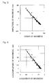
- FIG. 3 illustrates an example of measurement of the relation between the order of waviness and the amplitude of waviness occurring in the inner ring 2. It can be understood that a linear relation is established between them on a logarithmic scale.
- the harmonic analysis was carried out on waviness of the inner ring of the ball contact bearing assembly to determine the ratio ⁇ / ⁇ and, an acoustic test was then carried out after incorporation of the inner ring into the bearing assembly to experimentally examine the acoustic quality. As a result, it has been clarified that if the ratio ⁇ / ⁇ is equal to or more than 4, a problem would arise.
- the condition, under which the acoustic test was conducted included the use of a deep groove ball bearing identified by the bearing number 6203 according to the JIS (Japanese Industrial Standards) for a bearing assembly to be tested, the rotational speed of 1,800 rpm, the radial load of 2 kgf, and an oil lubrication.
- a circularity measuring instrument such as one tradenamed "TALYROND” was used.
- An waviness measuring instrument which is tradenamed "WEVIMETER” or the like may be used.
- the circularity measuring instrument with TALYROND is carried out by setting a bearing component part, which forms an object to be measured, on a table in alignment with the center of rotation of a detector, tracing a rolling surface (or a raceway surface in the case of the raceway ring) with a measuring probe fitted to the detector of a differential transformer type and converting the amount of swing thereof into an electric signal.
- the circularity waveform represented by this electric signal is processed with a computer to perform the harmonic analysis.
- the vibration in the bearing assembly can be reduced since at least one or more of the inner ring 2, the outer ring 3 and each of the rolling elements 4, all employed in the rolling contact bearing assembly 1 has no abnormal point as the ratio ⁇ / ⁇ is so chosen as to be smaller than 4 in connection with the relation between the order and the amplitude of waviness, which are in a linear relationship with each other.
Landscapes
- Engineering & Computer Science (AREA)
- General Engineering & Computer Science (AREA)
- Mechanical Engineering (AREA)
- Rolling Contact Bearings (AREA)
Abstract
Description
- The present invention relates to a rolling contact bearing assembly of a kind used in association with, for example, an electric motor.
- Any form errors a component part such as, for example, an inner ring, an outer ring or rolling elements all employed in a rolling contact bearing assembly, a machine having such rolling contact bearing assembly incorporated therein to generate vibrations. Accordingly, it has bean a general practice to minimize the circularity of rolling surfaces of the inner and outer rings and that of the rolling elements. Also, in the bearing assembly which is utilized with an axial preload applied, the waviness order present in waviness or undulation that lead to vibrations is fixed in view of the geometric relation and, therefore, minimization of the waviness of a particular order has been effective (See the
Non-patent Document 1 below.). - [Non-patent Document 1]
Sakaguchi, T. and Akamatsu, Y., "Simulation for Ball Bearing Vibration", NTN Technical Journal, No. 69, 2001, P69-75. - [Non-patent Document 2]
Proceedings of Conference on Tribology, Society of Tribology, November 2001, P291. - However, since in the case of a bearing assembly that is used in a gap condition, that is, in the case of a bearing assembly that is used in a condition in which a loaded region and a non-loaded region exist, tumbling elements (rolling elements and raceway rings) moving past the loaded region excite a stationary ring, vibration is not excited by waviness of any particular order, but is excited by every order of waviness. When the relation between the order of waviness and the amplitude of waviness is plotted on a logarithmic scale, it will exhibit a linear relation in the normal processing (See the
Non-patent Document 2 above.). - This is because vibration in the processing machine for the bearing part causes a form error of the bearing, and in general, the higher the degree of vibration is, the smaller the amplitude is. Accordingly, the amplitude or amount of the error of the processed surface in the bearing part decreases in accordance with advance of the order of waviness.
- Because of the above, a processing method to reduce the waviness have hitherto been employed in order to reduce the vibration occurring in the bearing assembly.
- However, even though the size of the waviness as a whole is small, vibrations (sounds) of the frequency determined by the waviness order and the rotational speed prevails if the waviness of a certain order is considerable, resulting in striking harshly upon the ears. Even though the level of vibrations (acoustics) is low, this characteristic is acoustically undesirable in the bearing assembly.
- In view of the foregoing, the present invention is intended to provide a rolling contact bearing assembly, in which generation of sounds of a prevailing frequency resulting from form errors of a rolling surface of a bearing component part can be suppressed and an increase in acoustic quality can be expected.
- The rolling contact bearing assembly of the present invention is of a design having the following relation between the order n and the amplitude r of waviness relative to the circularity of the sectional shape of a rolling surface of at least one of bearing component parts, including raceway rings or rolling elements, in which n represents an arbitrarily chosen natural number:
- That is, the order n and the amplitude r of waviness are logarithmically transformed to define X = Log (n) from the order n and Y = Log (rn) from the amplitude r of n-order, and the ratio δ/σ of the deviation δ at each X from the regression line of Y to the standard deviation σ is made smaller than 4 when the regression line of Y = aX + b is determined.
- It is to be noted that the rolling surface of each of the raceway rings referred to above means a raceway surface of such raceway ring.
- According to the above described construction, since the order and the magnitude of waviness in the rolling surface of the bearing component part are logarithmically transformed and the ratio δ/σ of the deviation δ from the determined regression line to the standard deviation σ is chosen to be made smaller than 4, all that form an abnormal point can be eliminated from the relation between the order and the amplitude of waviness, which form the linear relationship, and, therefore, vibrations occurring in the bearing assembly can be reduced. In particular, generation of prevailing sounds of particular frequency can be suppressed and, hence, the acoustic quality of the bearing assembly can be increased.
- Although the present invention can be applied to any type of rolling contact bearing assembly such as, for example, a ball contact bearing, a cylindrical roller bearing, a tapered roller bearing, a needle roller bearing, a self-aligning ball bearing or any other bearing and also to any type of bearing component parts such as, for example, an inner ring, an outer ring or rolling elements, the present invention is also applicable to, for example, a ball contact bearing, which makes use of a ball retainer, or a bearing assembly utilizing an inner ring, in which the ratio δ/σ is smaller than 4. In a preferred embodiment of the present invention, results of experiments are presented for a ball contact bearing, in which a ball retainer is utilized and the bearing component part is an inner ring.
- In the practice of the present invention, the order n and the amplitude r of waviness may be a numerical value that can be obtained by means of a harmonic analysis performed on a measurement signal obtained by measuring the rolling surface of the rolling component part and indicative of the amount of deflection relative to the circularity. The harmonic analysis is a method of determining the order n and the amplitude r of waviness by Fourier transforming the circularity wave form.
- In any event, the present invention will become more clearly understood from the following description of preferred embodiments thereof, when taken in conjunction with the accompanying drawings. However, the embodiments and the drawings are given only for the purpose of illustration and explanation, and are not to be taken as limiting the scope of the present invention in any way whatsoever, which scope is to be determined by the appended claims. In the accompanying drawings, like reference numerals are used to denote like parts throughout the several views, and:
-
Fig. 1 is a sectional view showing a rolling contact bearing assembly according to a preferred embodiment of the present invention; -
Fig. 2 is an explanatory diagram showing an example of waviness appearing in an inner ring raceway surface thereof; -
Fig. 3 is a graph showing an example of measurement of the relation between the order and the amplitude appearing in an inner ring; -
Fig. 4 is a graph showing results of logarithmic transformation of the relation shown inFig. 3 ; and -
Fig. 5 is a graph showing a deviation from a regression line and a standard deviation. - A preferred embodiment of the present invention will now be described with particular reference to
Figs. 1 to 5 . As shown inFig. 1 , a rollingcontact bearing assembly 1 is in the form of a ball contact bearing such as, for example, a deep groove ball bearing and includes aninner ring 2 and anouter ring 3, both of which are respective raceway members, and a plurality ofrolling elements 4 such as, for example, balls interposed betweenraceway surfaces outer rings retainer 5 for retaining therolling elements 4 in a circular row, and sealingmembers 6 for sealing opposite ends of a bearing space delimited between the inner andouter rings respective raceway surfaces outer rings retainer 5 has apocket 5a defined at a plurality of locations in a circumferential direction thereof with therolling elements 4 retained in thosepockets 5a. Theraceway surfaces outer rings rolling elements 4 form respective rolling surfaces of the inner andouter rings rolling elements 4, which are bearing component parts. - The sectional shape of an arbitrarily chosen diametric portion of each of the
rolling elements 4, which are in the form of balls, and the sectional shape of theraceway surface 2a of theinner ring 2 and theraceway surface 3a of theouter ring 3 as viewed in a direction perpendicular to a bearing longitudinal axis O should be ideally just round. However, as shown exaggeratedly inFig. 2 in connection with, for example, theinner ring 2, those sectional shapes have waviness or undulation, including some waves orhills 7, against the complete round C due to a form error in manufacture. It is to be noted that although inFig. 2 , the number of waves is shown as four (4) for the sake of clarity, the number n of thosewaves 7 or the order n of waviness and the amplitude r of waviness vary depending on the processing method. - In the embodiment now under discussion, the relation between the order n (n being an arbitrarily chosen natural number) and the amplitude r of waviness in any of the
raceway surface 2a in theinner ring 2, theraceway surface 3a in theouter ring 3 and the outer spherical surface of each of therolling elements 4 is so defined as follows: - Specifically, the order n and the amplitude r are logarithmically transformed to define X = Log (n) from the order n and Y = Log (rn) from the amplitude r of n-order, and the ratio δ/σ of the deviation δ at each X from the regression line of Y to the standard deviation σ is chosen to be smaller than 4 when the regression line of Y = aX + b is determined.
- It is to be noted that "a" represents a constant indicative of the gradient of the regression line and "b" represents a constant which forms an Y-axis intersection of the regression line.
- The order n and the amplitude r of waviness are a numerical value obtained by conducting the harmonic analysis, as will be described later, on the circularity of the bearing component part.
- It is to be noted that although in the foregoing embodiment, the relation between the order n and the amplitude r of waviness has been described such that in any of the
inner ring 2, theouter ring 3 and each of therolling elements 4, the ratio δ/σ can be so chosen as to be smaller than 4, the above discussed relation may be establish in at least one or more of theinner ring 2, theouter ring 3 and eachrolling element 4. - Hereinafter, results of experiments will be discussed.
Fig. 3 illustrates an example of measurement of the relation between the order of waviness and the amplitude of waviness occurring in theinner ring 2. It can be understood that a linear relation is established between them on a logarithmic scale. - A regression line is shown in
Fig. 3 and it is clear that the amplitude of order nine is prevailing. - Results of logarithmic transform of X-axes and Y-axes into Log X and Log Y, respectively, are shown in
Fig. 4 . - In this X-Y coordinate system, the standard deviation σ and the deviation δ at each X from the regression line of Y are calculated.
- Such relation is shown in
Fig. 5 and it can readily be seen that the ratio of the deviation of waviness of order nine to the standard deviation exceeds 4. - The harmonic analysis was carried out on waviness of the inner ring of the ball contact bearing assembly to determine the ratio δ/σ and, an acoustic test was then carried out after incorporation of the inner ring into the bearing assembly to experimentally examine the acoustic quality. As a result, it has been clarified that if the ratio δ/σ is equal to or more than 4, a problem would arise. The condition, under which the acoustic test was conducted, included the use of a deep groove ball bearing identified by the bearing number 6203 according to the JIS (Japanese Industrial Standards) for a bearing assembly to be tested, the rotational speed of 1,800 rpm, the radial load of 2 kgf, and an oil lubrication. Bearing acoustics were measured with a microphone and the acoustic quality was determined aurally. Results are tabulated in Table 1 below:
Table 1: Results of Acoustic Test Ratio δ/σ Acoustic Quality 2.0 O.K. 2.7 O.K. 3.2 O.K. 3.6 O.K. 3.8 O.K. 4.0 NO 4.3 NO - For the harmonic analysis of the waviness, a circularity measuring instrument, such as one tradenamed "TALYROND" was used. An waviness measuring instrument, which is tradenamed "WEVIMETER" or the like may be used. The circularity measuring instrument with TALYROND is carried out by setting a bearing component part, which forms an object to be measured, on a table in alignment with the center of rotation of a detector, tracing a rolling surface (or a raceway surface in the case of the raceway ring) with a measuring probe fitted to the detector of a differential transformer type and converting the amount of swing thereof into an electric signal. The circularity waveform represented by this electric signal is processed with a computer to perform the harmonic analysis. Data on the order of waviness which are used in a regression analysis were limited to 3 to 50. The waviness containing two orders has a generally large amplitude, but is unnecessary in discussing over the problem associated with vibrations since the frequency thereof is low. On the other hand, the waviness of order 50 or higher was exempted from the object of measurement partly because the measurement of such waviness requires a substantial number of measurement steps and partly because the number of occurrence of an abnormal waviness in lineup is small.
- The use of the same measurement conditions and the same analysis conditions on this occasion regardless of the type of bearing assembly and, also, the type of the bearing component results in no problem.
- As hereinabove discussed, the vibration in the bearing assembly can be reduced since at least one or more of the
inner ring 2, theouter ring 3 and each of the rollingelements 4, all employed in the rollingcontact bearing assembly 1 has no abnormal point as the ratio δ/σ is so chosen as to be smaller than 4 in connection with the relation between the order and the amplitude of waviness, which are in a linear relationship with each other. - In other words, in the present invention, the harmonic analysis is carried out on the waviness occurring in the rolling surface of each of the rolling
elements 4, theinner ring 2 and theouter ring 3 and, for the equation related with the order n and the amplitude r of waviness, the logarithmic transform is carried out to define X = Log (n) from the order n and Y = Log (rn) from the amplitude r of waviness containing the n-order so that the regression line Y = aX + b can be determined, and the deviation δ at each X from the regression line of Y is normalized by the standard deviation σ and the ratio δ/σ, which is the dimensionless number, is so chosen to be smaller than 4. Accordingly, generation of prevailing sounds of the particular frequency can be suppressed and the acoustic quality of the bearing assembly can be increased.
Claims (3)
- A rolling contact bearing assembly comprising bearing component parts including a raceway ring and a rolling element;
at least one of the bearing component parts having a rolling surface of a sectional shape having the following relation between the number n (n being an arbitrarily chosen natural number) and the amplitude r of waviness relative to the circularity:
logarithmically transforming the order n and the amplitude of waviness to define X = Log (n) from the order n and Y = Log (rn) from the amplitude r of n-order; and
when a regression line of Y = aX + b is determined, the ratio δ/σ of the deviation δ at each X from the regression line of Y to the standard deviation σ is made smaller than 4. - The rolling contact bearing assembly as claimed in Claim 1, wherein the bearing assembly is a ball contact bearing having a retainer and wherein an inner ring has the ratio δ/σ smaller than 4.
- The rolling contact bearing assembly as claimed in Claim 1, wherein the order n and the amplitude r of waviness represent a numerical value obtained by harmonic analysis of a measurement signal measured on the rolling surface of the bearing component part and indicative of an amount of swings relative to the circularity.
Applications Claiming Priority (2)
| Application Number | Priority Date | Filing Date | Title |
|---|---|---|---|
| JP2006085027A JP4969124B2 (en) | 2006-03-27 | 2006-03-27 | Rolling bearing sorting method |
| PCT/JP2007/000294 WO2007116581A1 (en) | 2006-03-27 | 2007-03-26 | Roller bearing |
Publications (3)
| Publication Number | Publication Date |
|---|---|
| EP2000685A1 true EP2000685A1 (en) | 2008-12-10 |
| EP2000685A4 EP2000685A4 (en) | 2012-10-03 |
| EP2000685B1 EP2000685B1 (en) | 2017-03-01 |
Family
ID=38580883
Family Applications (1)
| Application Number | Title | Priority Date | Filing Date |
|---|---|---|---|
| EP07736951.0A Ceased EP2000685B1 (en) | 2006-03-27 | 2007-03-26 | Method for determining quality of rolling bearing assembly |
Country Status (5)
| Country | Link |
|---|---|
| US (1) | US8104968B2 (en) |
| EP (1) | EP2000685B1 (en) |
| JP (1) | JP4969124B2 (en) |
| CN (1) | CN101410642B (en) |
| WO (1) | WO2007116581A1 (en) |
Families Citing this family (5)
| Publication number | Priority date | Publication date | Assignee | Title |
|---|---|---|---|---|
| JP2011080937A (en) * | 2009-10-09 | 2011-04-21 | Sumitomo Chemical Co Ltd | Inspection method of corrosion under heat insulating material |
| CN102022426B (en) * | 2010-11-26 | 2012-12-05 | 天津大学 | Method for improving running performance of rolling bearing |
| JP5894491B2 (en) * | 2012-04-16 | 2016-03-30 | Ntn株式会社 | Rolling bearing |
| JP2014152788A (en) * | 2013-02-05 | 2014-08-25 | Ntn Corp | Rolling bearing |
| CN107609245B (en) * | 2017-09-04 | 2020-10-30 | 杭州萧山鼎立机械有限公司 | Axial clearance correction method for interference fit of inner ring of hub bearing and flange plate |
Family Cites Families (20)
| Publication number | Priority date | Publication date | Assignee | Title |
|---|---|---|---|---|
| US3292980A (en) * | 1964-05-22 | 1966-12-20 | Skf Ind Inc | Rolling bearings |
| US3608244A (en) * | 1968-07-22 | 1971-09-28 | North American Rockwell | Cross raceway lapping of ball bearings |
| JP2961446B2 (en) * | 1991-03-20 | 1999-10-12 | 日本電産株式会社 | Rotating machine |
| JP3225618B2 (en) * | 1992-08-07 | 2001-11-05 | 日本精工株式会社 | Vibration inspection device |
| GB2288211B (en) * | 1994-04-06 | 1997-12-03 | Nsk Ltd | Vibration measurement system for a rolling bearing |
| US5782563A (en) * | 1995-03-10 | 1998-07-21 | Nsk Ltd. | Rolling bearing unit |
| JPH1066300A (en) * | 1996-08-19 | 1998-03-06 | Mitsubishi Electric Corp | Rotating electric machine |
| JPH10259451A (en) * | 1997-01-20 | 1998-09-29 | Nippon Seiko Kk | Rolling bearing |
| SE511232C2 (en) * | 1997-12-22 | 1999-08-30 | Skf Nova Ab | Procedure and apparatus for measuring the waviness of surfaces |
| JP4118993B2 (en) * | 1998-01-08 | 2008-07-16 | 日本電産株式会社 | Rotating machine |
| US6371653B2 (en) * | 1998-10-07 | 2002-04-16 | Minebea Co., Ltd. | Anti-friction bearing and a motor including such a bearing |
| JP2000167724A (en) * | 1998-12-07 | 2000-06-20 | Ntn Corp | Rolling bearing manufacturing facility |
| JP2002221228A (en) * | 2000-11-24 | 2002-08-09 | Nsk Ltd | Deep groove ball bearing and bearing device |
| CN2463597Y (en) * | 2000-12-29 | 2001-12-05 | 李千 | Slow-speed of revolution silencing nylon bearing |
| JP4203843B2 (en) * | 2002-08-05 | 2009-01-07 | 日本精工株式会社 | Rolling bearing and bearing device |
| JP2004116751A (en) * | 2002-09-30 | 2004-04-15 | Nsk Ltd | Rotary support device for pulley |
| JP2004308822A (en) * | 2003-04-09 | 2004-11-04 | Ntn Corp | Cylindrical roller bearing |
| CN2692406Y (en) * | 2004-04-20 | 2005-04-13 | 丽水市新亿特轴承有限公司 | Linear bearing |
| JP4753654B2 (en) * | 2005-08-03 | 2011-08-24 | Ntn株式会社 | Evaluation method for rolling bearing parts |
| US7421349B1 (en) * | 2006-05-15 | 2008-09-02 | United States Of America As Represented By The Secretary Of The Navy | Bearing fault signature detection |
-
2006
- 2006-03-27 JP JP2006085027A patent/JP4969124B2/en not_active Expired - Lifetime
-
2007
- 2007-03-26 CN CN2007800105641A patent/CN101410642B/en not_active Expired - Fee Related
- 2007-03-26 EP EP07736951.0A patent/EP2000685B1/en not_active Ceased
- 2007-03-26 WO PCT/JP2007/000294 patent/WO2007116581A1/en not_active Ceased
- 2007-03-26 US US12/225,532 patent/US8104968B2/en not_active Expired - Fee Related
Also Published As
| Publication number | Publication date |
|---|---|
| JP4969124B2 (en) | 2012-07-04 |
| EP2000685A4 (en) | 2012-10-03 |
| CN101410642A (en) | 2009-04-15 |
| US20090169144A1 (en) | 2009-07-02 |
| JP2007263136A (en) | 2007-10-11 |
| EP2000685B1 (en) | 2017-03-01 |
| WO2007116581A1 (en) | 2007-10-18 |
| US8104968B2 (en) | 2012-01-31 |
| CN101410642B (en) | 2010-12-08 |
Similar Documents
| Publication | Publication Date | Title |
|---|---|---|
| Su et al. | The effects of surface irregularities on roller bearing vibrations | |
| EP2000685B1 (en) | Method for determining quality of rolling bearing assembly | |
| Adamczak et al. | Influence of raceway waviness on the level of vibration in rolling-element bearings | |
| US8414194B2 (en) | Cylindrical roller bearing | |
| US5811683A (en) | Method and apparatus for location of anomalous signal in a radial bearing | |
| Adamczak et al. | Research of the influence of the 2D and 3D surface roughness parameters of bearing raceways on the vibration level | |
| Yhland | Paper 29: Waviness measurement-an instrument for quality control in rolling bearing industry | |
| Huang et al. | Mechanical behaviors of cross roller bearings with raceway roundness error | |
| US6453729B1 (en) | Surface shape evaluation method and device for spherical body | |
| Tong et al. | Characteristics of tapered roller bearing with geometric error | |
| EP1231394A2 (en) | Ball bearing cage | |
| US12305708B2 (en) | Retainer | |
| JP4753654B2 (en) | Evaluation method for rolling bearing parts | |
| Taha et al. | Acoustic Emission Application for Monitoring Bearing Defects | |
| Li et al. | Simulation and experimental validation of tapered roller bearing vibration induced by geometrical imperfection on cup raceway | |
| Rabeyee et al. | Diagnosing the change in the internal clearances of rolling element bearings based on vibration signatures | |
| Chen et al. | Analyzing vibration mechanism of angular contact ball bearing with compound faults on inner and outer rings | |
| Kumbhar et al. | Detection of the distributed defects on Inner and outer race of ball bearing using vibration analysis | |
| US20250044193A1 (en) | System and method for determining bearing preload by frequency measurement | |
| Nagale et al. | A mathematical model to determine sensitivity of vibration signals for localized defects and to find effective number of balls in ball bearing | |
| JP2008281157A (en) | Bearing device and bearing pre-load detection device | |
| Sesana et al. | Experimental and Statistical Study on the Noise Generated by Surface Defects of Bearing Rolling Bodies | |
| CN120659978A (en) | Bearing condition monitoring system | |
| Utpat et al. | A Modelfor Study of the Defects in Rolling Element Bearings at Higher Speed by Vibration Signature Analysis | |
| Rabeyee et al. | The Effect of Wear Evolution on Vibration-based Fault Detection in Tapered Roller Bearings |
Legal Events
| Date | Code | Title | Description |
|---|---|---|---|
| PUAI | Public reference made under article 153(3) epc to a published international application that has entered the european phase |
Free format text: ORIGINAL CODE: 0009012 |
|
| 17P | Request for examination filed |
Effective date: 20080919 |
|
| AK | Designated contracting states |
Kind code of ref document: A1 Designated state(s): DE FR |
|
| RBV | Designated contracting states (corrected) |
Designated state(s): DE FR |
|
| DAX | Request for extension of the european patent (deleted) | ||
| A4 | Supplementary search report drawn up and despatched |
Effective date: 20120904 |
|
| RIC1 | Information provided on ipc code assigned before grant |
Ipc: F16C 33/58 20060101AFI20120829BHEP Ipc: F16C 33/34 20060101ALI20120829BHEP Ipc: F16C 33/32 20060101ALI20120829BHEP |
|
| 17Q | First examination report despatched |
Effective date: 20130809 |
|
| GRAP | Despatch of communication of intention to grant a patent |
Free format text: ORIGINAL CODE: EPIDOSNIGR1 |
|
| INTG | Intention to grant announced |
Effective date: 20161115 |
|
| GRAS | Grant fee paid |
Free format text: ORIGINAL CODE: EPIDOSNIGR3 |
|
| GRAA | (expected) grant |
Free format text: ORIGINAL CODE: 0009210 |
|
| AK | Designated contracting states |
Kind code of ref document: B1 Designated state(s): DE FR |
|
| REG | Reference to a national code |
Ref country code: DE Ref legal event code: R096 Ref document number: 602007049956 Country of ref document: DE |
|
| REG | Reference to a national code |
Ref country code: FR Ref legal event code: PLFP Year of fee payment: 11 |
|
| REG | Reference to a national code |
Ref country code: DE Ref legal event code: R097 Ref document number: 602007049956 Country of ref document: DE |
|
| PLBE | No opposition filed within time limit |
Free format text: ORIGINAL CODE: 0009261 |
|
| STAA | Information on the status of an ep patent application or granted ep patent |
Free format text: STATUS: NO OPPOSITION FILED WITHIN TIME LIMIT |
|
| 26N | No opposition filed |
Effective date: 20171204 |
|
| REG | Reference to a national code |
Ref country code: FR Ref legal event code: PLFP Year of fee payment: 12 |
|
| PGFP | Annual fee paid to national office [announced via postgrant information from national office to epo] |
Ref country code: DE Payment date: 20190312 Year of fee payment: 13 |
|
| PGFP | Annual fee paid to national office [announced via postgrant information from national office to epo] |
Ref country code: FR Payment date: 20190213 Year of fee payment: 13 |
|
| REG | Reference to a national code |
Ref country code: DE Ref legal event code: R119 Ref document number: 602007049956 Country of ref document: DE |
|
| PG25 | Lapsed in a contracting state [announced via postgrant information from national office to epo] |
Ref country code: FR Free format text: LAPSE BECAUSE OF NON-PAYMENT OF DUE FEES Effective date: 20200331 Ref country code: DE Free format text: LAPSE BECAUSE OF NON-PAYMENT OF DUE FEES Effective date: 20201001 |