EP2000604B1 - Method for qualitative and quantitative waste water control in sewer emergency outlets - Google Patents
Method for qualitative and quantitative waste water control in sewer emergency outlets Download PDFInfo
- Publication number
- EP2000604B1 EP2000604B1 EP07011086A EP07011086A EP2000604B1 EP 2000604 B1 EP2000604 B1 EP 2000604B1 EP 07011086 A EP07011086 A EP 07011086A EP 07011086 A EP07011086 A EP 07011086A EP 2000604 B1 EP2000604 B1 EP 2000604B1
- Authority
- EP
- European Patent Office
- Prior art keywords
- sensor
- weir
- moving element
- wing
- sensor wing
- Prior art date
- Legal status (The legal status is an assumption and is not a legal conclusion. Google has not performed a legal analysis and makes no representation as to the accuracy of the status listed.)
- Not-in-force
Links
- 238000000034 method Methods 0.000 title claims abstract description 12
- 239000002351 wastewater Substances 0.000 title claims description 17
- 238000005259 measurement Methods 0.000 claims description 15
- 230000001419 dependent effect Effects 0.000 claims 1
- 239000000523 sample Substances 0.000 description 35
- 238000005086 pumping Methods 0.000 description 11
- 238000006073 displacement reaction Methods 0.000 description 8
- 230000007123 defense Effects 0.000 description 4
- 238000005516 engineering process Methods 0.000 description 3
- 238000007667 floating Methods 0.000 description 3
- XLYOFNOQVPJJNP-UHFFFAOYSA-N water Substances O XLYOFNOQVPJJNP-UHFFFAOYSA-N 0.000 description 3
- 238000011156 evaluation Methods 0.000 description 2
- 238000011835 investigation Methods 0.000 description 2
- 238000011160 research Methods 0.000 description 2
- 239000003643 water by type Substances 0.000 description 2
- 239000000470 constituent Substances 0.000 description 1
- 238000010276 construction Methods 0.000 description 1
- 239000000356 contaminant Substances 0.000 description 1
- 238000005260 corrosion Methods 0.000 description 1
- 230000007797 corrosion Effects 0.000 description 1
- 239000004615 ingredient Substances 0.000 description 1
- 239000002184 metal Substances 0.000 description 1
- 230000002035 prolonged effect Effects 0.000 description 1
- 239000010865 sewage Substances 0.000 description 1
- 238000013517 stratification Methods 0.000 description 1
- 238000012549 training Methods 0.000 description 1
- 238000011144 upstream manufacturing Methods 0.000 description 1
Images


Classifications
-
- E—FIXED CONSTRUCTIONS
- E03—WATER SUPPLY; SEWERAGE
- E03F—SEWERS; CESSPOOLS
- E03F5/00—Sewerage structures
- E03F5/12—Emergency outlets
-
- C—CHEMISTRY; METALLURGY
- C02—TREATMENT OF WATER, WASTE WATER, SEWAGE, OR SLUDGE
- C02F—TREATMENT OF WATER, WASTE WATER, SEWAGE, OR SLUDGE
- C02F2209/00—Controlling or monitoring parameters in water treatment
- C02F2209/001—Upstream control, i.e. monitoring for predictive control
-
- C—CHEMISTRY; METALLURGY
- C02—TREATMENT OF WATER, WASTE WATER, SEWAGE, OR SLUDGE
- C02F—TREATMENT OF WATER, WASTE WATER, SEWAGE, OR SLUDGE
- C02F2209/00—Controlling or monitoring parameters in water treatment
- C02F2209/06—Controlling or monitoring parameters in water treatment pH
-
- C—CHEMISTRY; METALLURGY
- C02—TREATMENT OF WATER, WASTE WATER, SEWAGE, OR SLUDGE
- C02F—TREATMENT OF WATER, WASTE WATER, SEWAGE, OR SLUDGE
- C02F2209/00—Controlling or monitoring parameters in water treatment
- C02F2209/11—Turbidity
-
- C—CHEMISTRY; METALLURGY
- C02—TREATMENT OF WATER, WASTE WATER, SEWAGE, OR SLUDGE
- C02F—TREATMENT OF WATER, WASTE WATER, SEWAGE, OR SLUDGE
- C02F2209/00—Controlling or monitoring parameters in water treatment
- C02F2209/14—NH3-N
-
- C—CHEMISTRY; METALLURGY
- C02—TREATMENT OF WATER, WASTE WATER, SEWAGE, OR SLUDGE
- C02F—TREATMENT OF WATER, WASTE WATER, SEWAGE, OR SLUDGE
- C02F2209/00—Controlling or monitoring parameters in water treatment
- C02F2209/20—Total organic carbon [TOC]
Definitions
- the invention includes a method for qualitative and quantitative wastewater control at discharge systems, in which a probe wing equipped with different probes immersed in a wastewater body below a relief control level and is moved as needed by one of the four different arrangements of Verschubelementen to layer by means of online measurement of the probes specify a height, qualitative and possibly quantitative modulation of the different discharge systems.
- the continuous quality measurement with a SAK probe on the weir edge has the disadvantage that an online measurement evaluation can take place only at a raid height with full coverage of the measurement window. Measurement evaluation is not possible in this case if the measurement window is not covered. With smaller reliefs, this leads to a higher error quotient, which is not responsible for a future measured value solution for discharge systems of the sewage system into the receiving waters.
- special quality probes such as P; NH4; TOC; SAK, NO 3 -N, turbidity; O 2 and pH are monitored and archived online.
- DE-A-40 16 378 discloses a generic method. Object of the present invention is that of the DE-A-40 16 378 to improve known methods. The object is achieved by a method having the features of claim 1. So that a proper displacement of the probe wings in the wastewater body can take place without critical clogging by wastewater contents in the area of the displacement elements (displacement cylinder, rope pulley guide) and the supply cable , these plant parts are surrounded by a flow protection in the entire wastewater body, which is firmly anchored in the floor area and ceiling area. In the arrangement of the probe wing on Verschubimplantations ( weir edge relief weir ) according to the method, the arrangement of a "floating baffle" considered an adequate and advantageous solution for flow protection.
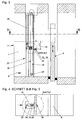
- the probe wing [18] equipped with different probes [12] to a predetermined height dimension ⁇ h [10] below the weir edge [30] of a vertically movable relief system (relief weir ) [5] is arranged.
- the control technology connection of the measuring probes [12] within the probe blade [18] is ensured by means of a correspondingly arranged supply cable [28] to the sliding rod head [15] which is designed to slide on all sides within the flow protection [22].
- FIG. 2 It shows in Fig. 2 according to the displacement element (Verschubzylinder) [23] a horizontal section "AA" according to Fig. 1 , from which it can be seen that the probe blade [18], which can be equipped with a plurality of probes [12], is connected to the push rod head [15] via a traverse [20] and can be moved vertically by means of a displacement cylinder [27] , Furthermore, the arrangement of Verschubiatas (Verschubzylinder) [23] within the Umströmungstikes [22] in the wastewater body [1] before the relief weir [8] in the flow direction [9] to the weir edge [30] can be seen.
- the displacement element Veryschubzylinder
- FIG. 5 It shows in Fig. 5 according to Verschubelement (movable pumping station) [25] a vertical section "CC" through a sewer system [11] with an integrated pumping station [13], in which against the flow direction [9] above a vertically ausberichtbaren relief system (pumping station) [6] a probe wing [18], via a traverse [20], with the height dimension ⁇ h [10] below the Ansaufflee [2] attached to the pumping station [13], with the pumping station [13] can be moved to uncritical wastewater quantities by online control a quality probe [14] to pump via the relief weir [8] with its weir edge [30] in a flood-leading receiving water [29], which in particular by the higher lying weir edge [30] of the relief weir [8] to the flood-leading receiving water [29] illustrates becomes. Furthermore, it can be seen that the measuring probes [12] of the probe wing [18] must be connected via a supply cable [28] to a control system
- a floating baffle [19] is arranged against the flow direction [9] above the probe wing [18].
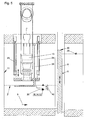
- FIG. 7 It shows in Fig. 7 in accordance with the displacement element (pulley guide) [24] a horizontal, enlarged section "BB" according to Fig. 4 from which it can be seen that the truss head [21] of the traverse [20] is attached to a pulley guide [16] within the flow-around protection [22] and further at least at the opposite location within the truss head [21] has a passage opening [4], so that a circumferential, vertical V flesh the pulley guide [16] can be achieved. Visible is also the supply cable [28], which must be connected via the traverse [20] control technology with the probe wing [18].
- FIG. 8 a detail magnification according to Figure 3 in which the positively sliding guidance of the truss head [21] on the cable pulley guide [16] within the flow protection [22] and furthermore the control technology connection of the associated measuring probes [12] of the probe wing [18] via the traverse [20] by means of a supply cable [28 ] is clarified.
- this Verschubelement (pulley guide) [24] necessary flow opening [4] for the pulley guide [16] of the truss head [21].
Landscapes
- Business, Economics & Management (AREA)
- Emergency Management (AREA)
- Health & Medical Sciences (AREA)
- Life Sciences & Earth Sciences (AREA)
- Engineering & Computer Science (AREA)
- Hydrology & Water Resources (AREA)
- Public Health (AREA)
- Water Supply & Treatment (AREA)
- Sewage (AREA)
- Hydroponics (AREA)
- Catching Or Destruction (AREA)
Abstract
Description
Die Erfindung beinhaltet ein Verfahren zur qualitativen und quantitativen Abwassersteuerung an Entlastungsanlagen, bei dem ein mit unterschiedlichen Messsonden bestückter Sondenflügel in einem Abwasserkörper unterhalb einer Entlastungssteuerungsebene eintaucht und je nach Bedarf durch eine der vier unterschiedlichen Anordnungen von Verschubelementen verfahren wird, um mittels schichtabhängiger Online Messung der Messsonden eine höhenmäßige, qualitative und gegebenenfalls quantitative Aussteuerung der unterschiedlichen Entlastungsanlagen vorzugeben.
Hierbei werden die Sondenflügel bei dem Verschubelement (Verschubzylinder) am Schubstangenkopf des Verschubzylinders, bei dem Verschubelement (Seilrollenführung) an der Seilrollenführung, bei dem Verschubelement (verfahrbare Pumpstaion) an der vertikal verfahrbaren Pumpstation, auch als Entlastungsanlage (Pumpstation) bezeichnet, mittels einer Traverse unterhalb der Ansaugebene und bei dem Verschubelement (Wehrkante Entlastungswehr) an einer vorgelagerten Traverse an der Wehrkante eines Entlastungswehres befestigt.
Die schichtweise Messung von Abwasserinhaltsstoffen in eingestauten Abwasserkörpern wurde zur Auswertung der Schmutzfrachtentlastung an der Entlastungswehranlage des Stauraumkanales in Burscheid Luisental, anlässlich des Forschungsvorhabens {1} mittels einer SAK Sonde, die fest auf der Wehrkante befestigt war, vorgenommen. Diese technische Umsetzung entspricht einem Detailaspekt der Beschreibung gemäß 
Here, the probe wings in the Verschubelement (Verschubzylinder) on the push rod head of the Verschubzylinders, the Verschubelement (pulley guide) on the pulley guide , the Verschubelement ( movable pumping station ) at the vertically movable pumping station, also referred to as relief system (pumping station) , by means of a traverse below the Ansaugebene and the Verschubelement (weir edge unloading weir ) attached to an upstream truss on the weir edge of a relief weir.
The stratified measurement of wastewater constituents in jammed wastewater bodies was carried out to evaluate the discharge of contaminants at the discharge defense system of the reservoir canal in Burscheid Luisental, on the occasion of the research project {1} by means of a SAK probe fixed firmly on the weir edge. This technical implementation corresponds to a detailed aspect of the description according to
-
{1} Prof. Dr.-Ing. Pinnekamp;
Untersuchung zum Entlastungs- und Betriebsverhalten von gesteuerten Stauraumkanälen mit mittiger Entlastung; Forschungsbericht der RWTH Aachen, August 2004 {1} Prof. Dr.-Ing. Pinnekamp;
Investigation of the unloading and operating behavior of controlled storage channels with central discharge; Research Report of RWTH Aachen University, August 2004 -
{2} Dipl.-Ing. M. Weikopf
Eigene Untersuchungen; ASA Technik GmbH 2003 {2} Dipl.-Ing. M. Weikopf
Own investigations; ASA Technik GmbH 2003
Die kontinuierliche Qualitätsmessung mit einer SAK Sonde auf der Wehrkante hat den Nachteil, dass erst bei einer Überfallhöhe mit voller Abdeckung des Messfensters eine Online Messauswertung stattfinden kann. Eine Messauswertung ist in diesem Fall nicht möglich, wenn das Messfenster nicht abgedeckt ist. Dies führt bei kleineren Entlastungen zu einem höheren Fehlerquotienten, der bei einer zukünftigen Messwertlösung für Entlastungsanlagen der Kanalisation in die Vorflut nicht zu vertreten ist. Darüber hinaus wird es zur Überwachung möglicher Entlastungskonzentrationen immer wichtiger, das diese unterschiedlichen Abwasserinhaltsstoffe durch spezielle Qualitätssonden wie z.B. Pges ; NH4; TOC; SAK, NO3-N, Trübung; O2 und pH online überwacht und archiviert werden.The continuous quality measurement with a SAK probe on the weir edge has the disadvantage that an online measurement evaluation can take place only at a raid height with full coverage of the measurement window. Measurement evaluation is not possible in this case if the measurement window is not covered. With smaller reliefs, this leads to a higher error quotient, which is not responsible for a future measured value solution for discharge systems of the sewage system into the receiving waters. In addition, to monitor possible release concentrations, it becomes increasingly important that these different wastewater ingredients be controlled by special quality probes , such as P; NH4; TOC; SAK, NO 3 -N, turbidity; O 2 and pH are monitored and archived online.
Aufgabe der vorliegenden Erfindung ist es, das aus der
Damit ein ordnungsgemäßer Verschub der Sondenflügel im Abwasserkörper ohne kritische Verzopfungen durch Abwasserinhaltsstoffe im Bereich der Verschubelemente (Verschubzylinder; Seilrollenführung) und der Versorgungskabel erfolgen kann, werden diese Anlagenteile mit einem Umströmungsschutz im gesamten Abwasserkörper umgeben, der im Sohlbereich und Deckenbereich fest verankert wird. Bei der Anordnung des Sondenflügels am Verschubelementes (Wehrkante Entlastungswehr) wird verfahrensgemäß die Anordnung einer "Schwimmenden Tauchwand" als adäquate und vorteilhafte Lösung zum Umströmungsschutz angesehen. Ansonsten ist ausbildungstechnisch vorgesehen, dass der Umströmungsschutz als korrosionsfeste Blechkonstruktion auch gleichzeitig als allseitiges Gleitlager für den Traversenkopf der Traverse insbesondere für die Verschubelemente (Verschubzylinder; Seilrollenführung) ausgebildet wird.
Mögliche Ausführungsbeispiele des Verfahrens und seiner technischen Umsetzung werden in den Zeichnungen näher erläutert:
Es zeigt in
Die steuerungstechnische Anbindung der Messsonden [12] innerhalb des Sondenflügels [18] wird über ein entsprechend angeordnetes Versorgungskabel [28] zum allseitig gleitend ausgebildeten Schubstangenkopf [15] innerhalb des Umströmungsschutzes [22] sichergestellt.
Object of the present invention is that of the
So that a proper displacement of the probe wings in the wastewater body can take place without critical clogging by wastewater contents in the area of the displacement elements (displacement cylinder, rope pulley guide) and the supply cable , these plant parts are surrounded by a flow protection in the entire wastewater body, which is firmly anchored in the floor area and ceiling area. In the arrangement of the probe wing on Verschubelementes ( weir edge relief weir ) according to the method, the arrangement of a "floating baffle" considered an adequate and advantageous solution for flow protection. Otherwise training is provided that the flow protection as corrosion-resistant sheet metal construction at the same time as all-round slide bearing for the truss head of Traverse especially for the Verschubelemente (Verschubzylinder; pulley guide) is formed.
Possible embodiments of the method and its technical implementation are explained in more detail in the drawings:
It shows in
The control technology connection of the measuring probes [12] within the probe blade [18] is ensured by means of a correspondingly arranged supply cable [28] to the sliding rod head [15] which is designed to slide on all sides within the flow protection [22].
Es zeigt in
Es zeigt in
Es zeigt in
Es zeigt in
Es zeigt in
Es zeigt in
Es zeigt in
- [1] Abwasserkörper[1] Wastewater body
- [2] Ansaugebene[2] Ansaugebene
- [3] Deckenbereich[3] ceiling area
- [4] Durchlauföffnung[4] Passage opening
- [5] Entlastungsanlage (Entlastungswehr) [5] Relief plant (relief defense)
- [6] Entlastungsanlage (Pumpstation) [6] Relief plant (pumping station)
- [7] Entlastungssteuerungsebene[7] Relief Control Level
- [8] Entlastungswehr[8] Relief Defense
- [9] Fließrichtung[9] flow direction
- [10] Höhenmaß Δh[10] Height dimension Δh
- [11] Kanalisationsanlage[11] Sewerage system
- [12] Messsonde[12] Probe
- [13] Pumpstation[13] pumping station
- [14] Qualitätssonde[14] Quality Probe
- [15] Schubstangenkopf[15] push rod head
- [16] Seilrollenführung[16] Pulley guide
- [17] Sohlbereich[17] Sole area
- [18] Sondenflügel[18] Probe wings
- [19] Tauchwand (schwimmend)[19] bog wall (floating)
- [20] Traverse[20] Traverse
- [21] Traversenkopf[21] Truss head
- [22] Umströmungsschutz[22] flow protection
- [23] Verschubelement (Verschubzylinder)[23] Verschubelement (Verschubzylinder)
- [24] Verschubelement (Seilrollenführung)[24] shifting element (pulley guide)
- [25] Verschubelement (verfahrbare Pumpstation)[25] Displacement element (movable pumping station)
- [26] Verschubelement (Wehrkante Entlastungswehr)[26] Verschubelement (weir edge relief defense)
- [27] Verschubzylinder[27] Shifting cylinder
- [28] Versorgungskabel[28] Supply cable
- [29] Vorfluter[29] receiving water
- [30] Wehrkante[30] Weir edge
Claims (4)
- Method for qualitative and quantitative waste water control in sewer emergency outlets [5]; [6] with different measurement sensors [12] which dip below a discharge level in a wastewater body [1] and by means of layer dependent online measuring using the measurement sensors [12] to provide a depth-related, qualitative and if necessary quantitative rejection of the respective emergency outlets [5]; [6] indicated by this,
that a sensor wing [18], which is equipped with several various measurement sensors [12] which can be raised or lowered by a moving element [23]; [24]; [25]; [26],
that in accordance with a first variant, where the moving element [23] means a moveable cylinder [27] on which the sensor wing [18] is fastened at the push rod head [15],
that in accordance with a second variant, where the moving element [24] means a pulley rope guidance [16] on which the sensor wing [18] is fastened and can be moved up and down,
that in accordance with a third variant, where the moving element [25] means a vertically lifting pump station, which one is described as an emergency outlet [6], where the sensor wing [18] by means of a sensor wing adapter [20] is fastened below an intake level [2], or
that in accordance with a fourth variant the moving element [26] means a vertically lifting discharge weir [8], where the sensor wing [18] is fastened at the sensor wing adapter [20] of the weir edge [30]. - Method pursuant to Claim 1, indicated by this, that the sensor wing [18] in the discharge mode of the emergency outlet [5]; [6] at least in the depth difference Δh [10] below the weir edge [30] of the discharge weir [8] designed as a emergency outlet [5] or in case of a vertical lifting pump station [13] designed as a emergency outlet [6] below of a non-critical intake level [2] is fixed and furthermore the moveable cylinder [27] or the pulley rope guidance [16] designed as moving elements [23]; [24] and the accompanying utility cables [28] connected to the measurement sensors [12] are surrounded with the circulation flow protection [22] from the invert reach [17] to the ceiling area [3] inside the wastewater body [1].
- Method pursuant to Claim 1 and 2, indicated by this, that the vertical rejection of the respective emergency outlet [5]; [6] below of the discharge level [7] or even respective intake level [2] in the case of a non-critical online measurement by at least one quality sensor [14] cause a lowering down; otherwise by an on-line recording of a critical quality measurement of at least one quality sensor [14] a lifting up of the weir will be performed.
- Method pursuant to Claim 1 to 3, indicated by this, that the sensor wing adapter head [21] of the sensor wing adapter [20] between the circulation flow protection [22] in order to the moving element [23] means that it can be guided all-around, but in the case of the moving element (pulley rope guidance) [24] a passageway opening [4] for the free-running pulley rope guidance [16] is available.
Priority Applications (3)
| Application Number | Priority Date | Filing Date | Title |
|---|---|---|---|
| DE502007004646T DE502007004646D1 (en) | 2007-06-06 | 2007-06-06 | Process for the qualitative and quantitative control of sewage at demining plants |
| EP07011086A EP2000604B1 (en) | 2007-06-06 | 2007-06-06 | Method for qualitative and quantitative waste water control in sewer emergency outlets |
| AT07011086T ATE476561T1 (en) | 2007-06-06 | 2007-06-06 | METHOD FOR QUALITATIVE AND QUANTITATIVE WASTEWATER CONTROL AT DEVELOPMENT PLANTS |
Applications Claiming Priority (1)
| Application Number | Priority Date | Filing Date | Title |
|---|---|---|---|
| EP07011086A EP2000604B1 (en) | 2007-06-06 | 2007-06-06 | Method for qualitative and quantitative waste water control in sewer emergency outlets |
Publications (2)
| Publication Number | Publication Date |
|---|---|
| EP2000604A1 EP2000604A1 (en) | 2008-12-10 |
| EP2000604B1 true EP2000604B1 (en) | 2010-08-04 |
Family
ID=38606459
Family Applications (1)
| Application Number | Title | Priority Date | Filing Date |
|---|---|---|---|
| EP07011086A Not-in-force EP2000604B1 (en) | 2007-06-06 | 2007-06-06 | Method for qualitative and quantitative waste water control in sewer emergency outlets |
Country Status (3)
| Country | Link |
|---|---|
| EP (1) | EP2000604B1 (en) |
| AT (1) | ATE476561T1 (en) |
| DE (1) | DE502007004646D1 (en) |
Families Citing this family (1)
| Publication number | Priority date | Publication date | Assignee | Title |
|---|---|---|---|---|
| EP2626332A1 (en) | 2012-02-11 | 2013-08-14 | Manfred Weikopf | Aeration of sludge with nozzles having specific diameter |
Family Cites Families (3)
| Publication number | Priority date | Publication date | Assignee | Title |
|---|---|---|---|---|
| DE4016378C2 (en) | 1990-05-21 | 1993-10-21 | Manfred Dipl Ing Weikopf | Instrumentation for simultaneous collection of overflow water quantities and quality characteristics of wastewater |
| DE4314198C2 (en) * | 1993-04-30 | 1996-02-22 | Kurt Dipl Ing Liebke | Device for monitoring the surface of a body of water for contaminants containing luminophores |
| DE59608256D1 (en) * | 1996-01-08 | 2002-01-03 | Va Tech Wabag Schweiz Ag Winte | Device for controllably dividing an incoming liquid flow |
-
2007
- 2007-06-06 AT AT07011086T patent/ATE476561T1/en active
- 2007-06-06 EP EP07011086A patent/EP2000604B1/en not_active Not-in-force
- 2007-06-06 DE DE502007004646T patent/DE502007004646D1/en active Active
Also Published As
| Publication number | Publication date |
|---|---|
| ATE476561T1 (en) | 2010-08-15 |
| DE502007004646D1 (en) | 2010-09-16 |
| EP2000604A1 (en) | 2008-12-10 |
Similar Documents
| Publication | Publication Date | Title |
|---|---|---|
| DE3629870C2 (en) | Sampling device for determining a concentration profile and its use | |
| EP2000604B1 (en) | Method for qualitative and quantitative waste water control in sewer emergency outlets | |
| DE102014108406B3 (en) | Method and device for determining the density of a floating body | |
| DE3248244C2 (en) | ||
| EP1995585B1 (en) | Process for determining the quality of fresh concrete | |
| EP0114408B1 (en) | Process for detecting the level of sludge, especially in settling pools of sewage treatment plants, and device for carrying out the process | |
| AT516154B1 (en) | Method for determining the risk of corrosion of installations | |
| EP3120908A1 (en) | Method and device for monitoring a separator | |
| DE3248243A1 (en) | Apparatus for measuring the turbidity of liquids, in particular for determining the sludge level in settling tanks of sewage treatment works | |
| DE8804409U1 (en) | Device for detection and/or measurement by phase separation and transition | |
| DE29616636U1 (en) | Device set for determining the degree of contamination of oil and fat separators in sewage systems | |
| BE1031679B1 (en) | Device and method for determining the water return flow rate during a hydrogeological exploration drilling using the direct directional drilling method | |
| DE102016104656A1 (en) | Method for measuring overflow in overflow systems | |
| DE102010025251B4 (en) | Underwater gas measuring device for the quantification of underwater gas leaking or their use | |
| DE3207357A1 (en) | Method and device for measuring the flow in open channels, particularly those carrying waste water | |
| AT506279A1 (en) | DISCONTINUOUS METHOD OF WASTEWATER CLEANING | |
| DE102005028636B4 (en) | Method and arrangement for determining the risk of corrosion in porous bodies | |
| DE102020133121B4 (en) | Method and device for measuring the overflow of a liquid over an overflow edge of a basin | |
| DE102015007648A1 (en) | Method and device for determining the weight of a measuring volume of a water-solid mixture and / or the density of a water-solid mixture | |
| DE4214113A1 (en) | Waste water shaft with units for sewage sample removal and taking sewage parameters - uses probe(s) immersed in waste water supplied and drained by gutter penetrating at right angles to shaft | |
| DE102009043134A1 (en) | Method for determining material exchange rate between water body and porous media, involves adjusting material concentration difference between water body and porous medium, and determining material concentration in body as function of time | |
| DE3706479A1 (en) | Process and apparatus for "in vivo" investigation of the complex interchange of substances and/or utilisation of substances of agroecological systems | |
| DE2405154C3 (en) | Hose level | |
| DE20308461U1 (en) | Floatable device for analyzing a liquid | |
| DE102011017774B4 (en) | Apparatus and method for preventing or reducing the formation of H2S, biogenic sulfuric acid and / or mercaptans in water-bearing pipe systems |
Legal Events
| Date | Code | Title | Description |
|---|---|---|---|
| PUAI | Public reference made under article 153(3) epc to a published international application that has entered the european phase |
Free format text: ORIGINAL CODE: 0009012 |
|
| AK | Designated contracting states |
Kind code of ref document: A1 Designated state(s): AT BE BG CH CY CZ DE DK EE ES FI FR GB GR HU IE IS IT LI LT LU LV MC MT NL PL PT RO SE SI SK TR |
|
| AX | Request for extension of the european patent |
Extension state: AL BA HR MK RS |
|
| RAP1 | Party data changed (applicant data changed or rights of an application transferred) |
Owner name: WEIKOPF, MANFRED |
|
| RIN1 | Information on inventor provided before grant (corrected) |
Inventor name: WEIKOPF, MANFRED |
|
| 17P | Request for examination filed |
Effective date: 20090515 |
|
| 17Q | First examination report despatched |
Effective date: 20090710 |
|
| AKX | Designation fees paid |
Designated state(s): AT BE BG CH CY CZ DE DK EE ES FI FR GB GR HU IE IS IT LI LT LU LV MC MT NL PL PT RO SE SI SK TR |
|
| R17C | First examination report despatched (corrected) |
Effective date: 20090901 |
|
| GRAP | Despatch of communication of intention to grant a patent |
Free format text: ORIGINAL CODE: EPIDOSNIGR1 |
|
| R17C | First examination report despatched (corrected) |
Effective date: 20091110 |
|
| GRAS | Grant fee paid |
Free format text: ORIGINAL CODE: EPIDOSNIGR3 |
|
| GRAA | (expected) grant |
Free format text: ORIGINAL CODE: 0009210 |
|
| AK | Designated contracting states |
Kind code of ref document: B1 Designated state(s): AT BE BG CH CY CZ DE DK EE ES FI FR GB GR HU IE IS IT LI LT LU LV MC MT NL PL PT RO SE SI SK TR |
|
| REG | Reference to a national code |
Ref country code: GB Ref legal event code: FG4D Free format text: NOT ENGLISH |
|
| REG | Reference to a national code |
Ref country code: CH Ref legal event code: EP |
|
| REG | Reference to a national code |
Ref country code: IE Ref legal event code: FG4D Free format text: LANGUAGE OF EP DOCUMENT: GERMAN |
|
| REF | Corresponds to: |
Ref document number: 502007004646 Country of ref document: DE Date of ref document: 20100916 Kind code of ref document: P |
|
| REG | Reference to a national code |
Ref country code: NL Ref legal event code: VDEP Effective date: 20100804 |
|
| LTIE | Lt: invalidation of european patent or patent extension |
Effective date: 20100804 |
|
| PG25 | Lapsed in a contracting state [announced via postgrant information from national office to epo] |
Ref country code: FI Free format text: LAPSE BECAUSE OF FAILURE TO SUBMIT A TRANSLATION OF THE DESCRIPTION OR TO PAY THE FEE WITHIN THE PRESCRIBED TIME-LIMIT Effective date: 20100804 Ref country code: NL Free format text: LAPSE BECAUSE OF FAILURE TO SUBMIT A TRANSLATION OF THE DESCRIPTION OR TO PAY THE FEE WITHIN THE PRESCRIBED TIME-LIMIT Effective date: 20100804 Ref country code: LT Free format text: LAPSE BECAUSE OF FAILURE TO SUBMIT A TRANSLATION OF THE DESCRIPTION OR TO PAY THE FEE WITHIN THE PRESCRIBED TIME-LIMIT Effective date: 20100804 |
|
| PG25 | Lapsed in a contracting state [announced via postgrant information from national office to epo] |
Ref country code: PT Free format text: LAPSE BECAUSE OF FAILURE TO SUBMIT A TRANSLATION OF THE DESCRIPTION OR TO PAY THE FEE WITHIN THE PRESCRIBED TIME-LIMIT Effective date: 20101206 Ref country code: SI Free format text: LAPSE BECAUSE OF FAILURE TO SUBMIT A TRANSLATION OF THE DESCRIPTION OR TO PAY THE FEE WITHIN THE PRESCRIBED TIME-LIMIT Effective date: 20100804 Ref country code: BG Free format text: LAPSE BECAUSE OF FAILURE TO SUBMIT A TRANSLATION OF THE DESCRIPTION OR TO PAY THE FEE WITHIN THE PRESCRIBED TIME-LIMIT Effective date: 20101104 Ref country code: CY Free format text: LAPSE BECAUSE OF FAILURE TO SUBMIT A TRANSLATION OF THE DESCRIPTION OR TO PAY THE FEE WITHIN THE PRESCRIBED TIME-LIMIT Effective date: 20100804 Ref country code: IS Free format text: LAPSE BECAUSE OF FAILURE TO SUBMIT A TRANSLATION OF THE DESCRIPTION OR TO PAY THE FEE WITHIN THE PRESCRIBED TIME-LIMIT Effective date: 20101204 Ref country code: PL Free format text: LAPSE BECAUSE OF FAILURE TO SUBMIT A TRANSLATION OF THE DESCRIPTION OR TO PAY THE FEE WITHIN THE PRESCRIBED TIME-LIMIT Effective date: 20100804 |
|
| REG | Reference to a national code |
Ref country code: IE Ref legal event code: FD4D |
|
| PG25 | Lapsed in a contracting state [announced via postgrant information from national office to epo] |
Ref country code: LV Free format text: LAPSE BECAUSE OF FAILURE TO SUBMIT A TRANSLATION OF THE DESCRIPTION OR TO PAY THE FEE WITHIN THE PRESCRIBED TIME-LIMIT Effective date: 20100804 Ref country code: GR Free format text: LAPSE BECAUSE OF FAILURE TO SUBMIT A TRANSLATION OF THE DESCRIPTION OR TO PAY THE FEE WITHIN THE PRESCRIBED TIME-LIMIT Effective date: 20101105 Ref country code: SE Free format text: LAPSE BECAUSE OF FAILURE TO SUBMIT A TRANSLATION OF THE DESCRIPTION OR TO PAY THE FEE WITHIN THE PRESCRIBED TIME-LIMIT Effective date: 20100804 |
|
| PG25 | Lapsed in a contracting state [announced via postgrant information from national office to epo] |
Ref country code: DK Free format text: LAPSE BECAUSE OF FAILURE TO SUBMIT A TRANSLATION OF THE DESCRIPTION OR TO PAY THE FEE WITHIN THE PRESCRIBED TIME-LIMIT Effective date: 20100804 Ref country code: IE Free format text: LAPSE BECAUSE OF FAILURE TO SUBMIT A TRANSLATION OF THE DESCRIPTION OR TO PAY THE FEE WITHIN THE PRESCRIBED TIME-LIMIT Effective date: 20100804 |
|
| PG25 | Lapsed in a contracting state [announced via postgrant information from national office to epo] |
Ref country code: CZ Free format text: LAPSE BECAUSE OF FAILURE TO SUBMIT A TRANSLATION OF THE DESCRIPTION OR TO PAY THE FEE WITHIN THE PRESCRIBED TIME-LIMIT Effective date: 20100804 Ref country code: RO Free format text: LAPSE BECAUSE OF FAILURE TO SUBMIT A TRANSLATION OF THE DESCRIPTION OR TO PAY THE FEE WITHIN THE PRESCRIBED TIME-LIMIT Effective date: 20100804 Ref country code: SK Free format text: LAPSE BECAUSE OF FAILURE TO SUBMIT A TRANSLATION OF THE DESCRIPTION OR TO PAY THE FEE WITHIN THE PRESCRIBED TIME-LIMIT Effective date: 20100804 Ref country code: IT Free format text: LAPSE BECAUSE OF FAILURE TO SUBMIT A TRANSLATION OF THE DESCRIPTION OR TO PAY THE FEE WITHIN THE PRESCRIBED TIME-LIMIT Effective date: 20100804 Ref country code: EE Free format text: LAPSE BECAUSE OF FAILURE TO SUBMIT A TRANSLATION OF THE DESCRIPTION OR TO PAY THE FEE WITHIN THE PRESCRIBED TIME-LIMIT Effective date: 20100804 |
|
| PLBE | No opposition filed within time limit |
Free format text: ORIGINAL CODE: 0009261 |
|
| STAA | Information on the status of an ep patent application or granted ep patent |
Free format text: STATUS: NO OPPOSITION FILED WITHIN TIME LIMIT |
|
| PG25 | Lapsed in a contracting state [announced via postgrant information from national office to epo] |
Ref country code: ES Free format text: LAPSE BECAUSE OF FAILURE TO SUBMIT A TRANSLATION OF THE DESCRIPTION OR TO PAY THE FEE WITHIN THE PRESCRIBED TIME-LIMIT Effective date: 20101115 |
|
| 26N | No opposition filed |
Effective date: 20110506 |
|
| PGFP | Annual fee paid to national office [announced via postgrant information from national office to epo] |
Ref country code: CH Payment date: 20110627 Year of fee payment: 5 |
|
| REG | Reference to a national code |
Ref country code: DE Ref legal event code: R097 Ref document number: 502007004646 Country of ref document: DE Effective date: 20110506 |
|
| PG25 | Lapsed in a contracting state [announced via postgrant information from national office to epo] |
Ref country code: MT Free format text: LAPSE BECAUSE OF FAILURE TO SUBMIT A TRANSLATION OF THE DESCRIPTION OR TO PAY THE FEE WITHIN THE PRESCRIBED TIME-LIMIT Effective date: 20100804 |
|
| BERE | Be: lapsed |
Owner name: WEIKOPF, MANFRED Effective date: 20110630 |
|
| GBPC | Gb: european patent ceased through non-payment of renewal fee |
Effective date: 20110606 |
|
| PG25 | Lapsed in a contracting state [announced via postgrant information from national office to epo] |
Ref country code: BE Free format text: LAPSE BECAUSE OF NON-PAYMENT OF DUE FEES Effective date: 20110630 |
|
| PG25 | Lapsed in a contracting state [announced via postgrant information from national office to epo] |
Ref country code: GB Free format text: LAPSE BECAUSE OF NON-PAYMENT OF DUE FEES Effective date: 20110606 |
|
| PGFP | Annual fee paid to national office [announced via postgrant information from national office to epo] |
Ref country code: DE Payment date: 20120809 Year of fee payment: 6 |
|
| PGFP | Annual fee paid to national office [announced via postgrant information from national office to epo] |
Ref country code: FR Payment date: 20121121 Year of fee payment: 6 |
|
| PGFP | Annual fee paid to national office [announced via postgrant information from national office to epo] |
Ref country code: AT Payment date: 20120810 Year of fee payment: 6 |
|
| PG25 | Lapsed in a contracting state [announced via postgrant information from national office to epo] |
Ref country code: MC Free format text: LAPSE BECAUSE OF NON-PAYMENT OF DUE FEES Effective date: 20110630 |
|
| PG25 | Lapsed in a contracting state [announced via postgrant information from national office to epo] |
Ref country code: LU Free format text: LAPSE BECAUSE OF NON-PAYMENT OF DUE FEES Effective date: 20110606 |
|
| PG25 | Lapsed in a contracting state [announced via postgrant information from national office to epo] |
Ref country code: TR Free format text: LAPSE BECAUSE OF FAILURE TO SUBMIT A TRANSLATION OF THE DESCRIPTION OR TO PAY THE FEE WITHIN THE PRESCRIBED TIME-LIMIT Effective date: 20100804 |
|
| PG25 | Lapsed in a contracting state [announced via postgrant information from national office to epo] |
Ref country code: HU Free format text: LAPSE BECAUSE OF FAILURE TO SUBMIT A TRANSLATION OF THE DESCRIPTION OR TO PAY THE FEE WITHIN THE PRESCRIBED TIME-LIMIT Effective date: 20100804 |
|
| REG | Reference to a national code |
Ref country code: CH Ref legal event code: PL |
|
| REG | Reference to a national code |
Ref country code: AT Ref legal event code: MM01 Ref document number: 476561 Country of ref document: AT Kind code of ref document: T Effective date: 20130606 |
|
| REG | Reference to a national code |
Ref country code: FR Ref legal event code: ST Effective date: 20140228 |
|
| REG | Reference to a national code |
Ref country code: DE Ref legal event code: R119 Ref document number: 502007004646 Country of ref document: DE Effective date: 20140101 |
|
| PG25 | Lapsed in a contracting state [announced via postgrant information from national office to epo] |
Ref country code: LI Free format text: LAPSE BECAUSE OF NON-PAYMENT OF DUE FEES Effective date: 20130630 Ref country code: DE Free format text: LAPSE BECAUSE OF NON-PAYMENT OF DUE FEES Effective date: 20140101 Ref country code: CH Free format text: LAPSE BECAUSE OF NON-PAYMENT OF DUE FEES Effective date: 20130630 |
|
| PG25 | Lapsed in a contracting state [announced via postgrant information from national office to epo] |
Ref country code: AT Free format text: LAPSE BECAUSE OF NON-PAYMENT OF DUE FEES Effective date: 20130606 Ref country code: FR Free format text: LAPSE BECAUSE OF NON-PAYMENT OF DUE FEES Effective date: 20130701 |