EP2000331A2 - Valve-integrated transponder - Google Patents
Valve-integrated transponder Download PDFInfo
- Publication number
- EP2000331A2 EP2000331A2 EP08010482A EP08010482A EP2000331A2 EP 2000331 A2 EP2000331 A2 EP 2000331A2 EP 08010482 A EP08010482 A EP 08010482A EP 08010482 A EP08010482 A EP 08010482A EP 2000331 A2 EP2000331 A2 EP 2000331A2
- Authority
- EP
- European Patent Office
- Prior art keywords
- valve
- antenna element
- supporting member
- casing
- air valve
- Prior art date
- Legal status (The legal status is an assumption and is not a legal conclusion. Google has not performed a legal analysis and makes no representation as to the accuracy of the status listed.)
- Withdrawn
Links
Images

Classifications
-
- B—PERFORMING OPERATIONS; TRANSPORTING
- B60—VEHICLES IN GENERAL
- B60C—VEHICLE TYRES; TYRE INFLATION; TYRE CHANGING; CONNECTING VALVES TO INFLATABLE ELASTIC BODIES IN GENERAL; DEVICES OR ARRANGEMENTS RELATED TO TYRES
- B60C23/00—Devices for measuring, signalling, controlling, or distributing tyre pressure or temperature, specially adapted for mounting on vehicles; Arrangement of tyre inflating devices on vehicles, e.g. of pumps or of tanks; Tyre cooling arrangements
- B60C23/02—Signalling devices actuated by tyre pressure
- B60C23/04—Signalling devices actuated by tyre pressure mounted on the wheel or tyre
- B60C23/0408—Signalling devices actuated by tyre pressure mounted on the wheel or tyre transmitting the signals by non-mechanical means from the wheel or tyre to a vehicle body mounted receiver
- B60C23/0422—Signalling devices actuated by tyre pressure mounted on the wheel or tyre transmitting the signals by non-mechanical means from the wheel or tyre to a vehicle body mounted receiver characterised by the type of signal transmission means
- B60C23/0433—Radio signals
- B60C23/0447—Wheel or tyre mounted circuits
- B60C23/0452—Antenna structure, control or arrangement
-
- B—PERFORMING OPERATIONS; TRANSPORTING
- B60—VEHICLES IN GENERAL
- B60C—VEHICLE TYRES; TYRE INFLATION; TYRE CHANGING; CONNECTING VALVES TO INFLATABLE ELASTIC BODIES IN GENERAL; DEVICES OR ARRANGEMENTS RELATED TO TYRES
- B60C23/00—Devices for measuring, signalling, controlling, or distributing tyre pressure or temperature, specially adapted for mounting on vehicles; Arrangement of tyre inflating devices on vehicles, e.g. of pumps or of tanks; Tyre cooling arrangements
- B60C23/02—Signalling devices actuated by tyre pressure
- B60C23/04—Signalling devices actuated by tyre pressure mounted on the wheel or tyre
- B60C23/0491—Constructional details of means for attaching the control device
- B60C23/0494—Valve stem attachments positioned inside the tyre chamber
Definitions
- the present invention relates to a valve-integrated transponder that is integrated with an air valve fixed to a valve hole of a wheel rim and is disposed in a tire, and that is used in a system for monitoring the air pressure of the tire.
- transponder of this type is integrally joined to, for example, an end of an air valve that is located within a tire. See Japanese Unexamined Patent Application Publication No. 2006-69389 (pages 3 to 5, and Fig. 1 ) for an example of such a valve-integrated transponder.
- the air valve may be of a clamp-in type that is screwed onto a wheel rim or a snap-in type that is press-fitted to a valve hole of a wheel rim.
- an air valve of a snap-in type is advantageous in that it can be readily fitted to a wheel rim.
- the type of built-in antenna to be used in a transponder contained inside a tire is not particularly limited, an inverse F antenna element made by forming a metal plate is advantageous in terms of low fabrication cost and compactness.
- a valve-integrated transponder of the related art normally contains a battery power source.
- the frequency of detecting the air pressure of a tire will need to be minimized to expand the life of the battery, and a complicated process will inevitably be necessary when replacing the battery.
- a valve-integrated transponder that does not require a battery power source has been proposed.
- the antenna element inside the tire is excited by a radio wave sent from an external antenna in the vehicle body and is supplied with a signal current based on information detected by the detecting element.
- Such a valve-integrated transponder not requiring a battery can allow for an increase in the frequency of detecting the air pressure of the tire and can thus achieve higher detection accuracy.
- the valve-integrated transponder also allows for lower maintenance costs due to not requiring a battery replacement process.
- a radio wave radiating from an antenna element of a valve-integrated transponder is transmitted to an external antenna in the vehicle body by passing through a side wall of a tire.
- the radio wave used has a short wavelength and has a strong property of rectilinear propagation, such as a 2.4 GHz radio wave used in a transponder that does not require a battery, it is necessary to increase radiation components of a direct wave directed from the antenna element in the tire towards the side wall.
- a radio wave radiates both upward and sideward from a radiation conductor. This makes it difficult for the radio wave to radiate efficiently towards the side wall of the tire.
- the transponder receives a large amount of force when the air valve is being press-fitted to the valve hole of the wheel rim.
- a casing which houses an antenna element and the like, with a reinforcement rib that extends along an extension of the axis of the air valve.
- providing such a reinforcement rib in a manner that it does not come in physical contact with the common inverse F antenna element is problematic in that the casing becomes large in size.
- the present invention provides a valve-integrated transponder in which a radio wave can radiate efficiently from a built-in antenna element towards a side wall of a tire, and in which a casing integrated with an air valve can be increased in mechanical strength without being increased in size.
- the present invention provides a valve-integrated transponder that includes a detecting element that detects a condition inside a tire; an inverse F antenna element that outputs information detected by the detecting element to an outside; a synthetic-resin supporting member that supports the antenna element; and a synthetic-resin casing that houses the detecting element, the antenna element, and the supporting member.
- the casing is joined to an end of an air valve fixed to a valve hole in a wheel rim, the end of the air valve being located inside the tire.
- a longitudinal direction of each of the antenna element and the supporting member is substantially perpendicular to an axial direction of the air valve.
- the casing is provided with a partition-like reinforcement rib extending across a space in the casing that accommodates the antenna element, the reinforcement rib extending along an extension of an axis of the air valve.
- a central section of the antenna element in the longitudinal direction thereof is provided with a feed terminal and a ground terminal, the antenna element having a substantially line symmetrical shape where a pair of radiation conductors extend symmetrically from the feed terminal and the ground terminal toward opposite longitudinal ends of the antenna element.
- the supporting member has a recessed slot in which the reinforcement rib is loosely fitted, the recessed slot being located between the pair of radiation conductors.
- the valve-integrated transponder fitted with the air valve in this manner contains the inverted F antenna element, and this antenna element has a substantially line symmetrical shape with the two radiation conductors extending symmetrically toward the opposite longitudinal ends of the antenna element from the central section thereof where the feed terminal and the ground terminal are provided.
- the radiation fields above the radiation conductors cancel each other out, thereby increasing the field intensity of radio waves radiating laterally from the radiation conductors. This allows for efficient radiation of radio waves from the antenna element contained in the valve-integrated transponder towards the side wall of the tire.
- the casing of the valve-integrated transponder is provided with the partition-like reinforcement rib that extends across the space accommodating the antenna element while being located on an extension of the axis of the air valve. Consequently, when the air valve is being press-fitted to the valve hole of the wheel rim, the casing can be prevented from being damaged.
- the reinforcement rib of the casing is loosely fitted in the recessed slot of the supporting member, which is located between the two radiation conductors of the antenna element, the casing does not need to be increased in size for avoiding contact between the reinforcement rib and the antenna element.
- the antenna element be made by forming a metal plate so that the manufacturing cost of the antenna element can be reduced.
- the supporting member may have a central erected portion that defines a contour of the recessed slot and a pair of holder surfaces extending from the central erected portion along the pair of radiation conductors, the central erected portion supporting the feed terminal and the ground terminal, the holder surfaces supporting the radiation conductors.
- the ground terminal may be disposed along one side surface of the central erected portion, and the feed terminal may be extended along an inner bottom surface of the recessed slot to another side surface of the central erected portion.
- the ground terminal may be disposed along one side surface of the central erected portion, and the feed terminal may be disposed along another side surface of the central erected portion.
- the antenna element of the valve-integrated transponder be excited by a radio wave from an external antenna attached to a vehicle body. Consequently, the valve-integrated transponder can allow for an increase in the frequency of detecting the air pressure of the tire and can thus achieve higher detection accuracy. In addition, the valve-integrated transponder also allows for lower maintenance costs due to not requiring a battery replacement process.
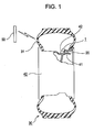
- Fig. 1 illustrates a mounting position of a valve-integrated transponder according to a first embodiment of the present invention inside a tire.
- Fig. 2 is an external view of the transponder and an air valve.
- Fig. 3 is a cross-sectional view taken along line III-III in Fig. 2 .
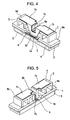
- Fig. 4 illustrates the internal structure of the transponder as viewed from an external-antenna side.
- Fig. 5 illustrates the internal structure of the transponder as viewed from an air-valve side.
- a valve-integrated transponder 1 shown in these drawings is fitted to one end of a snap-in type air valve 20 and disposed within a tire 30, and is for enabling a driver at the driver seat to monitor the air pressure and temperature inside the tire 30.
- the transponder 1 has a synthetic-resin casing 10 that houses a detection circuit unit 2 having detecting elements such as a pressure sensor and a temperature sensor, a transmitter/receiver circuit unit 3, a substrate 4 having these circuit units 2 and 3 mounted on a first surface thereof, a shield cover 5 formed of sheet metal that covers both the circuit units 2 and 3, a synthetic-resin supporting member 6 disposed on a second surface of the substrate 4, and an inverse F antenna element 7 that is supported by the supporting member 6 and electrically connected to the transmitter/receiver circuit unit 3.
- the transponder 1 does not contain a battery power source. Instead, the transponder 1 is configured such that the antenna element 7 is excited by a radio wave from an external antenna 50 (see Fig. 1 ) provided in the vehicle body.
- the air valve 20 is securely press-fitted in a valve hole 41 of a wheel rim 40, and the casing 10 is attached to an end portion of the air valve 20 that is located within the tire 30, such that the longitudinal direction of the antenna element 7 and the supporting member 6 are set substantially perpendicular to the axial direction of the air valve 20. Consequently, the transponder 1 is disposed within the tire 30 at an outer side of a well 42 of the wheel rim 40 as viewed in the radial direction of the tire 30.
- the casing 10 is a housing that is formed by joining together a casing body 11 and a lid body 12.
- the casing body 11 has a space 11a for accommodating a main_portion of the transponder 1.
- the lid body 12 covers a side of the casing body 11 that exposes the space 11a.
- a first side surface of the casing body 11 has a central section in the longitudinal direction thereof, from which a connector portion 10a engageable to the air valve 20 extends.
- a second side surface of the casing body 11 has a central section in the longitudinal direction thereof, which is provided with an air hole 10b that takes in the air in the tire 30.
- the casing body 11 has therein a partition-like reinforcement rib 11b that extends across the space 11a to separate the space 11a into two sections.
- the reinforcement rib 11b extends along an extension of the axis of the air valve 20.
- the detection circuit unit 2 has the detecting elements such as the pressure sensor and the temperature sensor for detecting the pressure and temperature of the air in the tire 30 that is introduced into the casing 10 through the air hole 10b.
- the transmitter/receiver circuit unit 3 receives an inquiry signal sent from the external antenna 50 in the vehicle body to the antenna element 7, and also receives a signal (detection signal) based on the detected information from the detection circuit unit 2.
- the transmitter/receiver circuit unit 3 processes this detection signal and outputs the processed signal to the antenna element 7.
- the detection circuit unit 2 and the transmitter/receiver circuit unit 3 are mounted on one surface of the substrate 4 (i.e. a first main surface of the substrate 4 that faces the well 42) while being covered with the shield cover 5.
- the detection circuit unit 2 and the transmitter/receiver circuit unit 3 are electromagnetically shielded by the shield cover 5 and are therefore hardly susceptible to external noise.
- a second main surface of the substrate 4 opposite to the first main surface thereof facing the well 42 is provided with a ground electrode 8 and a feed electrode 9, and holds thereon the supporting member 6.
- This supporting member 6 supports the antenna element 7.
- the external antenna 50 is installed in a tire house (not shown) of the vehicle body that faces a side wall 31 of the tire 30.
- the supporting member 6 includes a flat base portion 6a securely attached on the second main surface of the substrate 4 and a central erected portion 6c extending upright from a central region of the base portion 6a and defining the contour of a recessed slot 6b.
- the top surface of the supporting member 6 is constituted by a pair of flat holder surfaces 6d.
- An intermediate region between the holder surfaces 6d in the longitudinal direction of the supporting member 6 is defined by the opening of the recessed slot 6b.
- the reinforcement rib 11b of the casing body 11 is loosely fitted in this recessed slot 6b.
- the antenna element 7 is made by forming a metal plate, but has a significantly different shape to that of a common inverse F antenna element.
- the antenna element 7 is formed into a substantially line symmetrical shape and has a pair of radiation conductors 7c symmetrically extending toward opposite longitudinal ends of the antenna element 7 from a central section in the longitudinal direction thereof where a ground terminal 7a and a feed terminal 7b are disposed.
- the radiation fields above the radiation conductors 7c cancel each other out, thereby increasing the field intensity of radio waves radiating laterally from the radiation conductors 7c.
- the radiation conductors 7c are securely attached on the respective holder surfaces 6d of the supporting member 6, such that the two radiation conductors 7c have the opening of the recessed slot 6b located therebetween.
- the ground terminal 7a is disposed along a first side surface of the central erected portion 6c of the supporting member 6 and is soldered to the ground electrode 8.
- the feed terminal 7b is extended along an inner bottom surface of the recessed slot 6b to a second side surface of the central erected portion 6c and is soldered to the feed electrode 9.
- 2.4 GHz radio waves are used for transmission and reception of signals between the antenna element 7 and the external antenna 50 in the vehicle body. Therefore, a radio wave sent from the antenna element 7 to the external antenna 50 as a response signal is mainly a direct wave directed from the antenna element 7 towards the side wall 31 of the tire 30.
- the valve-integrated transponder 1 is disposed within the tire 30 by press-fitting the air valve 20 into the valve hole 41 of the wheel rim 40.
- the casing 10 of the transponder 1 receives a large amount of force when the air valve 20 is being press-fitted to the valve hole 41, the casing 10 is given sufficient mechanical strength that prevents it from being damaged during the press-fitting process of the air valve 20.
- Such mechanical strength is achieved by providing the casing 10 with the partition-like reinforcement rib 11b extending across the space 11a and located on an extension of the axis of the air valve 20.
- valve-integrated transponder 1 disposed within the tire 30 receives a radio wave as an inquiry signal from the external antenna 50 in the vehicle body, the antenna element 7 is excited and thus generates a high-frequency current. Then, the information about the air pressure and the temperature in the tire 30 detected by the pressure sensor and the temperature sensor is superposed on this high-frequency current, and the signal current (detection signal) is sent from the detection circuit unit 2 to the transmitter/receiver circuit unit 3. The transmitter/receiver circuit unit 3 processes this detection signal and outputs the processed signal to the antenna element 7. Thus, the antenna element 7 sends a radio wave as a response signal to the external antenna 50.
- the inverse F antenna element 7 contained in the valve-integrated transponder 1 has a substantially line symmetrical shape with the radiation conductors 7c extending symmetrically toward the opposite longitudinal ends of the antenna element 7 from the central section in the longitudinal direction thereof where the ground terminal 7a and the feed terminal 7b are disposed. Consequently, the radiation fields above the radiation conductors 7c cancel each other out, whereby the field intensity of radio waves radiating laterally from the radiation conductors 7c is increased. This allows for efficient radiation of radio waves from the antenna element 7 towards the side wall 31 of the tire 30.
- the valve-integrated transponder 1 is designed to increase the radiation components of a direct wave directed from the antenna element 7 towards the side wall 31. Accordingly, a radio wave as a response signal can be reliably sent to the external antenna 50 in the vehicle body.
- the casing 10 of the valve-integrated transponder 1 is provided with the partition-like reinforcement rib 11b that extends across the space 11a accommodating the antenna element 7 while being located on an extension of the axis of the air valve 20. Consequently, when the air valve 20 is being press-fitted to the valve hole 41 of the wheel rim 40, the casing 10 can be prevented from being damaged.
- the reinforcement rib 11b of the casing 10 is loosely fitted in the recessed slot 6b of the supporting member 6, which is located between the two radiation conductors 7c of the antenna element 7, the casing 10 does not need to be increased in size for avoiding contact between the reinforcement rib 11b and the antenna element 7.
- valve-integrated transponder 1 does not have a battery power source, and is configured such that the antenna element 7 is excited by a radio wave from the external antenna 50 attached to the vehicle body.
- This configuration allows for an increase in the detection frequency as well as lower maintenance costs.
- the antenna element 7 can be fabricated at low cost by forming a metal plate. Furthermore, since the antenna element 7 is stably supported by the supporting member 6, the antenna element 7 is highly resistant to deformation.
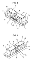
- Fig. 6 illustrates the internal structure of a valve-integrated transponder according to a second embodiment of the present invention as viewed from an external-antenna side.
- Fig. 7 illustrates the internal structure of the transponder as viewed from an air-valve side.
- the components shown in Figs. 6 and 7 that correspond to those in Figs. 4 and 5 are indicated with the same reference numerals, and descriptions of those components will not be repeated.
- the second embodiment differs from the first embodiment in the shape of the feed terminal 7b of the antenna element 7.
- the feed terminal 7b has a U-shaped segment 7d and is disposed along a side surface of the central erected portion 6c of the supporting member 6, the side surface being opposite to that provided with the ground terminal 7a.
- Opposite ends of the U-shaped segment 7d are continuously connected to the pair of radiation conductors 7c that are arranged side by side with the recessed slot 6b therebetween.
- the feed terminal 7b also has a linear segment that extends downward from the U-shaped segment 7d. The linear segment is soldered to the feed electrode 9.
- the air valve described in the above embodiments is of a snap-in type that is press-fitted to a valve hole of a wheel rim
- the present invention may alternatively be applied to an air valve of a clamp-in type that is screwed onto a wheel rim.
Landscapes
- Engineering & Computer Science (AREA)
- Mechanical Engineering (AREA)
- Measuring Fluid Pressure (AREA)
- Arrangements For Transmission Of Measured Signals (AREA)
Abstract
Description
- The present invention relates to a valve-integrated transponder that is integrated with an air valve fixed to a valve hole of a wheel rim and is disposed in a tire, and that is used in a system for monitoring the air pressure of the tire.
- In recent years, more and more vehicles are equipped with a system that enables a driver at the driver seat to monitor the air pressure of the tires. Specifically, such a system is provided for allowing a driver to quickly check the air pressure of the tires and to see whether the air pressure is abnormal while driving a vehicle, and is realized by installing transponders equipped with detecting elements and antenna elements in appropriate positions within the tires. A transponder of this type is integrally joined to, for example, an end of an air valve that is located within a tire. See Japanese Unexamined Patent Application Publication No.
2006-69389 pages 3 to 5, andFig. 1 ) for an example of such a valve-integrated transponder. In this case, the air valve may be of a clamp-in type that is screwed onto a wheel rim or a snap-in type that is press-fitted to a valve hole of a wheel rim. As described in Japanese Unexamined Patent Application Publication No.2006-69389 - A valve-integrated transponder of the related art normally contains a battery power source. However, with a structure equipped with a battery, the frequency of detecting the air pressure of a tire will need to be minimized to expand the life of the battery, and a complicated process will inevitably be necessary when replacing the battery. Recently, a valve-integrated transponder that does not require a battery power source has been proposed. Specifically, in this valve-integrated transponder, the antenna element inside the tire is excited by a radio wave sent from an external antenna in the vehicle body and is supplied with a signal current based on information detected by the detecting element. Such a valve-integrated transponder not requiring a battery can allow for an increase in the frequency of detecting the air pressure of the tire and can thus achieve higher detection accuracy. In addition, the valve-integrated transponder also allows for lower maintenance costs due to not requiring a battery replacement process.
- Generally, a radio wave radiating from an antenna element of a valve-integrated transponder is transmitted to an external antenna in the vehicle body by passing through a side wall of a tire. If the radio wave used has a short wavelength and has a strong property of rectilinear propagation, such as a 2.4 GHz radio wave used in a transponder that does not require a battery, it is necessary to increase radiation components of a direct wave directed from the antenna element in the tire towards the side wall. However, with a common inverse F antenna element, a radio wave radiates both upward and sideward from a radiation conductor. This makes it difficult for the radio wave to radiate efficiently towards the side wall of the tire. Regarding a valve-integrated transponder fitted to a snap-in type air valve, the transponder receives a large amount of force when the air valve is being press-fitted to the valve hole of the wheel rim. To enhance the mechanical strength of the transponder, it is desirable to provide a casing, which houses an antenna element and the like, with a reinforcement rib that extends along an extension of the axis of the air valve. However, providing such a reinforcement rib in a manner that it does not come in physical contact with the common inverse F antenna element is problematic in that the casing becomes large in size.
- The present invention provides a valve-integrated transponder in which a radio wave can radiate efficiently from a built-in antenna element towards a side wall of a tire, and in which a casing integrated with an air valve can be increased in mechanical strength without being increased in size.
- The present invention provides a valve-integrated transponder that includes a detecting element that detects a condition inside a tire; an inverse F antenna element that outputs information detected by the detecting element to an outside; a synthetic-resin supporting member that supports the antenna element; and a synthetic-resin casing that houses the detecting element, the antenna element, and the supporting member. The casing is joined to an end of an air valve fixed to a valve hole in a wheel rim, the end of the air valve being located inside the tire. A longitudinal direction of each of the antenna element and the supporting member is substantially perpendicular to an axial direction of the air valve. The casing is provided with a partition-like reinforcement rib extending across a space in the casing that accommodates the antenna element, the reinforcement rib extending along an extension of an axis of the air valve. A central section of the antenna element in the longitudinal direction thereof is provided with a feed terminal and a ground terminal, the antenna element having a substantially line symmetrical shape where a pair of radiation conductors extend symmetrically from the feed terminal and the ground terminal toward opposite longitudinal ends of the antenna element. The supporting member has a recessed slot in which the reinforcement rib is loosely fitted, the recessed slot being located between the pair of radiation conductors.
- As described above, the valve-integrated transponder fitted with the air valve in this manner contains the inverted F antenna element, and this antenna element has a substantially line symmetrical shape with the two radiation conductors extending symmetrically toward the opposite longitudinal ends of the antenna element from the central section thereof where the feed terminal and the ground terminal are provided. Thus, the radiation fields above the radiation conductors cancel each other out, thereby increasing the field intensity of radio waves radiating laterally from the radiation conductors. This allows for efficient radiation of radio waves from the antenna element contained in the valve-integrated transponder towards the side wall of the tire. Furthermore, in order to enhance the mechanical strength, the casing of the valve-integrated transponder is provided with the partition-like reinforcement rib that extends across the space accommodating the antenna element while being located on an extension of the axis of the air valve. Consequently, when the air valve is being press-fitted to the valve hole of the wheel rim, the casing can be prevented from being damaged. In addition, since the reinforcement rib of the casing is loosely fitted in the recessed slot of the supporting member, which is located between the two radiation conductors of the antenna element, the casing does not need to be increased in size for avoiding contact between the reinforcement rib and the antenna element.
- In the above configuration, it is preferable that the antenna element be made by forming a metal plate so that the manufacturing cost of the antenna element can be reduced. In this case, the supporting member may have a central erected portion that defines a contour of the recessed slot and a pair of holder surfaces extending from the central erected portion along the pair of radiation conductors, the central erected portion supporting the feed terminal and the ground terminal, the holder surfaces supporting the radiation conductors. Thus, the antenna element formed of a metal plate can be supported in a stable fashion, whereby the antenna element can be properly prevented from being deformed while the vehicle is running. As an example of a structure for supporting the feed terminal and the ground terminal by utilizing the central erected portion, the ground terminal may be disposed along one side surface of the central erected portion, and the feed terminal may be extended along an inner bottom surface of the recessed slot to another side surface of the central erected portion. Alternatively, the ground terminal may be disposed along one side surface of the central erected portion, and the feed terminal may be disposed along another side surface of the central erected portion.
- Furthermore, in the above configuration, it is preferable that the antenna element of the valve-integrated transponder be excited by a radio wave from an external antenna attached to a vehicle body. Consequently, the valve-integrated transponder can allow for an increase in the frequency of detecting the air pressure of the tire and can thus achieve higher detection accuracy. In addition, the valve-integrated transponder also allows for lower maintenance costs due to not requiring a battery replacement process.
-
-
Fig. 1 illustrates a mounting position of a valve-integrated transponder according to a first embodiment of the present invention inside a tire; -
Fig. 2 is an external view of the transponder shown inFig. 1 and an air valve; -
Fig. 3 is a cross-sectional view taken along line III-III inFig. 2 ; -
Fig. 4 illustrates the internal structure of the transponder according to the first embodiment as viewed from an external-antenna side; -
Fig. 5 illustrates the internal structure of the transponder according to the first embodiment as viewed from an air-valve side; -
Fig. 6 illustrates the internal structure of a valve-integrated transponder according to a second embodiment of the present invention as viewed from an external-antenna side; and -
Fig. 7 illustrates the internal structure of the transponder according to the second embodiment as viewed from an air-valve side. - Embodiments of the present invention will now be described with reference to the drawings.
Fig. 1 illustrates a mounting position of a valve-integrated transponder according to a first embodiment of the present invention inside a tire.Fig. 2 is an external view of the transponder and an air valve.Fig. 3 is a cross-sectional view taken along line III-III inFig. 2 .Fig. 4 illustrates the internal structure of the transponder as viewed from an external-antenna side.Fig. 5 illustrates the internal structure of the transponder as viewed from an air-valve side. - A valve-integrated
transponder 1 shown in these drawings is fitted to one end of a snap-intype air valve 20 and disposed within atire 30, and is for enabling a driver at the driver seat to monitor the air pressure and temperature inside thetire 30. Thetransponder 1 has a synthetic-resin casing 10 that houses adetection circuit unit 2 having detecting elements such as a pressure sensor and a temperature sensor, a transmitter/receiver circuit unit 3, asubstrate 4 having thesecircuit units shield cover 5 formed of sheet metal that covers both thecircuit units resin supporting member 6 disposed on a second surface of thesubstrate 4, and an inverseF antenna element 7 that is supported by the supportingmember 6 and electrically connected to the transmitter/receiver circuit unit 3. Thetransponder 1 does not contain a battery power source. Instead, thetransponder 1 is configured such that theantenna element 7 is excited by a radio wave from an external antenna 50 (seeFig. 1 ) provided in the vehicle body. Referring toFig. 1 , theair valve 20 is securely press-fitted in avalve hole 41 of awheel rim 40, and thecasing 10 is attached to an end portion of theair valve 20 that is located within thetire 30, such that the longitudinal direction of theantenna element 7 and the supportingmember 6 are set substantially perpendicular to the axial direction of theair valve 20. Consequently, thetransponder 1 is disposed within thetire 30 at an outer side of a well 42 of thewheel rim 40 as viewed in the radial direction of thetire 30. - The
casing 10 is a housing that is formed by joining together a casing body 11 and alid body 12. The casing body 11 has aspace 11a for accommodating a main_portion of thetransponder 1. Thelid body 12 covers a side of the casing body 11 that exposes thespace 11a. A first side surface of the casing body 11 has a central section in the longitudinal direction thereof, from which aconnector portion 10a engageable to theair valve 20 extends. On the other hand, a second side surface of the casing body 11 has a central section in the longitudinal direction thereof, which is provided with anair hole 10b that takes in the air in thetire 30. Moreover, referring toFig. 3 , the casing body 11 has therein a partition-like reinforcement rib 11b that extends across thespace 11a to separate thespace 11a into two sections. Thereinforcement rib 11b extends along an extension of the axis of theair valve 20. - The
detection circuit unit 2 has the detecting elements such as the pressure sensor and the temperature sensor for detecting the pressure and temperature of the air in thetire 30 that is introduced into thecasing 10 through theair hole 10b. The transmitter/receiver circuit unit 3 receives an inquiry signal sent from theexternal antenna 50 in the vehicle body to theantenna element 7, and also receives a signal (detection signal) based on the detected information from thedetection circuit unit 2. The transmitter/receiver circuit unit 3 processes this detection signal and outputs the processed signal to theantenna element 7. Thedetection circuit unit 2 and the transmitter/receiver circuit unit 3 are mounted on one surface of the substrate 4 (i.e. a first main surface of thesubstrate 4 that faces the well 42) while being covered with theshield cover 5. Accordingly, thedetection circuit unit 2 and the transmitter/receiver circuit unit 3 are electromagnetically shielded by theshield cover 5 and are therefore hardly susceptible to external noise. Referring toFigs. 4 and 5 , a second main surface of thesubstrate 4 opposite to the first main surface thereof facing the well 42 is provided with aground electrode 8 and afeed electrode 9, and holds thereon the supportingmember 6. This supportingmember 6 supports theantenna element 7. Theexternal antenna 50 is installed in a tire house (not shown) of the vehicle body that faces aside wall 31 of thetire 30. - The supporting
member 6 includes aflat base portion 6a securely attached on the second main surface of thesubstrate 4 and a central erectedportion 6c extending upright from a central region of thebase portion 6a and defining the contour of a recessedslot 6b. The top surface of the supportingmember 6 is constituted by a pair offlat holder surfaces 6d. An intermediate region between the holder surfaces 6d in the longitudinal direction of the supportingmember 6 is defined by the opening of the recessedslot 6b. Referring toFig. 3 , thereinforcement rib 11b of the casing body 11 is loosely fitted in this recessedslot 6b. - The
antenna element 7 is made by forming a metal plate, but has a significantly different shape to that of a common inverse F antenna element. Theantenna element 7 is formed into a substantially line symmetrical shape and has a pair ofradiation conductors 7c symmetrically extending toward opposite longitudinal ends of theantenna element 7 from a central section in the longitudinal direction thereof where aground terminal 7a and afeed terminal 7b are disposed. Thus, the radiation fields above theradiation conductors 7c cancel each other out, thereby increasing the field intensity of radio waves radiating laterally from theradiation conductors 7c. Theradiation conductors 7c are securely attached on therespective holder surfaces 6d of the supportingmember 6, such that the tworadiation conductors 7c have the opening of the recessedslot 6b located therebetween. Thereinforcement rib 11b loosely fitted in the recessedslot 6b intervenes the tworadiation conductors 7c so as to function as a partition. Referring toFig. 4 , theground terminal 7a is disposed along a first side surface of the central erectedportion 6c of the supportingmember 6 and is soldered to theground electrode 8. On the other hand, referring toFig. 5 , thefeed terminal 7b is extended along an inner bottom surface of the recessedslot 6b to a second side surface of the central erectedportion 6c and is soldered to thefeed electrode 9. For transmission and reception of signals between theantenna element 7 and theexternal antenna 50 in the vehicle body, 2.4 GHz radio waves are used. Therefore, a radio wave sent from theantenna element 7 to theexternal antenna 50 as a response signal is mainly a direct wave directed from theantenna element 7 towards theside wall 31 of thetire 30. - As mentioned above, the valve-integrated
transponder 1 is disposed within thetire 30 by press-fitting theair valve 20 into thevalve hole 41 of thewheel rim 40. Although thecasing 10 of thetransponder 1 receives a large amount of force when theair valve 20 is being press-fitted to thevalve hole 41, thecasing 10 is given sufficient mechanical strength that prevents it from being damaged during the press-fitting process of theair valve 20. Such mechanical strength is achieved by providing thecasing 10 with the partition-like reinforcement rib 11b extending across thespace 11a and located on an extension of the axis of theair valve 20. - When such a valve-integrated
transponder 1 disposed within thetire 30 receives a radio wave as an inquiry signal from theexternal antenna 50 in the vehicle body, theantenna element 7 is excited and thus generates a high-frequency current. Then, the information about the air pressure and the temperature in thetire 30 detected by the pressure sensor and the temperature sensor is superposed on this high-frequency current, and the signal current (detection signal) is sent from thedetection circuit unit 2 to the transmitter/receiver circuit unit 3. The transmitter/receiver circuit unit 3 processes this detection signal and outputs the processed signal to theantenna element 7. Thus, theantenna element 7 sends a radio wave as a response signal to theexternal antenna 50. - As described above, in the first embodiment, the inverse
F antenna element 7 contained in the valve-integratedtransponder 1 has a substantially line symmetrical shape with theradiation conductors 7c extending symmetrically toward the opposite longitudinal ends of theantenna element 7 from the central section in the longitudinal direction thereof where theground terminal 7a and thefeed terminal 7b are disposed. Consequently, the radiation fields above theradiation conductors 7c cancel each other out, whereby the field intensity of radio waves radiating laterally from theradiation conductors 7c is increased. This allows for efficient radiation of radio waves from theantenna element 7 towards theside wall 31 of thetire 30. In other words, the valve-integratedtransponder 1 is designed to increase the radiation components of a direct wave directed from theantenna element 7 towards theside wall 31. Accordingly, a radio wave as a response signal can be reliably sent to theexternal antenna 50 in the vehicle body. - As described above, in order to enhance the mechanical strength, the
casing 10 of the valve-integratedtransponder 1 is provided with the partition-like reinforcement rib 11b that extends across thespace 11a accommodating theantenna element 7 while being located on an extension of the axis of theair valve 20. Consequently, when theair valve 20 is being press-fitted to thevalve hole 41 of thewheel rim 40, thecasing 10 can be prevented from being damaged. In addition, since thereinforcement rib 11b of thecasing 10 is loosely fitted in the recessedslot 6b of the supportingmember 6, which is located between the tworadiation conductors 7c of theantenna element 7, thecasing 10 does not need to be increased in size for avoiding contact between thereinforcement rib 11b and theantenna element 7. - Furthermore, the valve-integrated
transponder 1 does not have a battery power source, and is configured such that theantenna element 7 is excited by a radio wave from theexternal antenna 50 attached to the vehicle body. This configuration allows for an increase in the detection frequency as well as lower maintenance costs. Theantenna element 7 can be fabricated at low cost by forming a metal plate. Furthermore, since theantenna element 7 is stably supported by the supportingmember 6, theantenna element 7 is highly resistant to deformation. -
Fig. 6 illustrates the internal structure of a valve-integrated transponder according to a second embodiment of the present invention as viewed from an external-antenna side.Fig. 7 illustrates the internal structure of the transponder as viewed from an air-valve side. The components shown inFigs. 6 and 7 that correspond to those inFigs. 4 and 5 are indicated with the same reference numerals, and descriptions of those components will not be repeated. - The second embodiment differs from the first embodiment in the shape of the
feed terminal 7b of theantenna element 7. Specifically, referring toFigs. 6 and '7, thefeed terminal 7b has aU-shaped segment 7d and is disposed along a side surface of the central erectedportion 6c of the supportingmember 6, the side surface being opposite to that provided with theground terminal 7a. Opposite ends of theU-shaped segment 7d are continuously connected to the pair ofradiation conductors 7c that are arranged side by side with the recessedslot 6b therebetween. Thefeed terminal 7b also has a linear segment that extends downward from theU-shaped segment 7d. The linear segment is soldered to thefeed electrode 9. - Although the air valve described in the above embodiments is of a snap-in type that is press-fitted to a valve hole of a wheel rim, the present invention may alternatively be applied to an air valve of a clamp-in type that is screwed onto a wheel rim.
Claims (6)
- A valve-integrated transponder (1) comprising:a detecting element that detects a condition inside a tire (30);an inverse F antenna element (7) that outputs information detected by the detecting element to an outside;a synthetic-resin supporting member (6) that supports the antenna element; anda synthetic-resin casing (10) that houses the detecting element, the antenna element, and the supporting member,wherein the casing is joined to an end of an air valve (20) fixed to a valve hole (41) in a wheel rim (40), the end of the air valve being located inside the tire, and wherein a longitudinal direction of each of the antenna element and the supporting member is substantially perpendicular to an axial direction of the air valve,
wherein the casing is provided with a partition-like reinforcement rib (11b-) extending across a space (11a) in the casing that accommodates the antenna element, the reinforcement rib extending along an extension of an axis of the air valve,
wherein a central section of the antenna element in the longitudinal direction thereof is provided with a feed terminal (7b) and a ground terminal (7a), the antenna element having a substantially line symmetrical shape where a pair of radiation conductors (7c) extend symmetrically from the feed terminal and the ground terminal toward opposite longitudinal ends of the antenna element, and
wherein the supporting member has a recessed slot (6b) in which the reinforcement rib is loosely fitted, the recessed slot being located between the pair of radiation conductors. - The valve-integrated transponder according to Claim 1, wherein the antenna element is made by forming a metal plate.
- The valve-integrated transponder according to Claim 1 or 2, wherein the supporting member has a central erected portion (6c) that defines a contour of the recessed slot and a pair of holder surfaces (6d) extending from the central erected portion along the pair of radiation conductors, the central erected portion supporting the feed terminal and the ground terminal, the holder surfaces supporting the radiation conductors.
- The valve-integrated transponder according to Claim 3, wherein the ground terminal is disposed along one side surface of the central erected portion, and wherein the feed terminal is extended along an inner bottom surface of the recessed slot to another side surface of the central erected portion.
- The valve-integrated transponder according to Claim 3, wherein the ground terminal is disposed along one side surface of the central erected portion, and wherein the feed terminal is disposed along another side surface of the central erected portion.
- The valve-integrated transponder according to any one of Claims 1 to 5, wherein the antenna element is excited by a radio wave from an external antenna (50) attached to a vehicle body.
Applications Claiming Priority (1)
| Application Number | Priority Date | Filing Date | Title |
|---|---|---|---|
| JP2007151633A JP5019957B2 (en) | 2007-06-07 | 2007-06-07 | Valve integrated transponder |
Publications (2)
| Publication Number | Publication Date |
|---|---|
| EP2000331A2 true EP2000331A2 (en) | 2008-12-10 |
| EP2000331A3 EP2000331A3 (en) | 2012-06-27 |
Family
ID=39745431
Family Applications (1)
| Application Number | Title | Priority Date | Filing Date |
|---|---|---|---|
| EP08010482A Withdrawn EP2000331A3 (en) | 2007-06-07 | 2008-06-09 | Valve-integrated transponder |
Country Status (3)
| Country | Link |
|---|---|
| US (1) | US7804397B2 (en) |
| EP (1) | EP2000331A3 (en) |
| JP (1) | JP5019957B2 (en) |
Cited By (2)
| Publication number | Priority date | Publication date | Assignee | Title |
|---|---|---|---|---|
| CN103282218A (en) * | 2011-01-18 | 2013-09-04 | 横滨橡胶株式会社 | Transmitting device for transmitting tire state-related information, tire assembly, and tire state monitoring system |
| FR3067977A1 (en) * | 2017-06-27 | 2018-12-28 | Continental Automotive France | ELECTRONIC UNIT FOR MEASURING OPERATING PARAMETERS OF A VEHICLE WHEEL |
Families Citing this family (3)
| Publication number | Priority date | Publication date | Assignee | Title |
|---|---|---|---|---|
| US8474312B2 (en) * | 2011-12-02 | 2013-07-02 | Josn Electronic Co., Ltd. | Tire pressure monitor |
| CN104417293B (en) * | 2013-09-09 | 2017-03-01 | 嵩镕精密工业股份有限公司 | tire pressure sensor |
| DE102015118598A1 (en) * | 2015-10-30 | 2017-05-04 | Cleverciti Systems Gmbh | METHOD FOR RECORDING PARKED VEHICLES AND BILLING PARKING FEES |
Family Cites Families (17)
| Publication number | Priority date | Publication date | Assignee | Title |
|---|---|---|---|---|
| JPH04199904A (en) * | 1990-11-29 | 1992-07-21 | Nissan Motor Co Ltd | Antenna device for vehicles |
| TW404354U (en) * | 1999-03-30 | 2000-09-01 | Huang Teng Yi | Power supply unit installation structure for a hiding type tire pressure detector |
| JP2001292016A (en) * | 2000-04-04 | 2001-10-19 | Sony Corp | PC card |
| JP2002264621A (en) * | 2001-03-12 | 2002-09-18 | Pacific Ind Co Ltd | Transmitter of tire condition monitoring device |
| JP2003165315A (en) * | 2001-12-03 | 2003-06-10 | Bridgestone Corp | Tire internal pressure alarm device |
| JP2003182321A (en) * | 2001-12-17 | 2003-07-03 | Pacific Ind Co Ltd | Transmitter of tyre state monitoring device |
| DE10228737A1 (en) * | 2002-01-09 | 2003-07-24 | Lite On Automotive Corp | Tire condition sensor for pneumatic tires |
| US6729180B2 (en) * | 2002-09-25 | 2004-05-04 | Delphi Technologies, Inc. | Packaging for RF signal sensor with battery changing capabilities and method of using |
| JP2004294413A (en) * | 2003-02-12 | 2004-10-21 | Pacific Ind Co Ltd | Pressure sensor, transmitter, and tire condition monitor |
| JP2005039754A (en) * | 2003-06-26 | 2005-02-10 | Alps Electric Co Ltd | Antenna system |
| JP2006074369A (en) * | 2004-09-01 | 2006-03-16 | Pacific Ind Co Ltd | Transmitter for tire state monitoring device, and antenna used therefor |
| JP2006069389A (en) | 2004-09-02 | 2006-03-16 | Toyota Motor Corp | Wheel-mounted communication unit and wheels |
| US6993962B1 (en) * | 2005-03-11 | 2006-02-07 | Yueh-Ying Ko | Electronic wireless tire pressure monitoring apparatus |
| US7284418B2 (en) * | 2005-06-03 | 2007-10-23 | Temic Automotive Of North America, Inc. | Tire pressure sensor assembly |
| US20060273890A1 (en) * | 2005-06-03 | 2006-12-07 | Christos Kontogeorgakis | Tire pressure monitoring system |
| JP2007126026A (en) * | 2005-11-04 | 2007-05-24 | Alps Electric Co Ltd | Antenna device |
| JP2008011385A (en) * | 2006-06-30 | 2008-01-17 | Alps Electric Co Ltd | Antenna unit |
-
2007
- 2007-06-07 JP JP2007151633A patent/JP5019957B2/en not_active Expired - Fee Related
-
2008
- 2008-06-05 US US12/133,696 patent/US7804397B2/en not_active Expired - Fee Related
- 2008-06-09 EP EP08010482A patent/EP2000331A3/en not_active Withdrawn
Cited By (5)
| Publication number | Priority date | Publication date | Assignee | Title |
|---|---|---|---|---|
| CN103282218A (en) * | 2011-01-18 | 2013-09-04 | 横滨橡胶株式会社 | Transmitting device for transmitting tire state-related information, tire assembly, and tire state monitoring system |
| CN103282218B (en) * | 2011-01-18 | 2016-10-26 | 横滨橡胶株式会社 | Transmitting device for transmitting tire state-related information, tire assembly, and tire state monitoring system |
| FR3067977A1 (en) * | 2017-06-27 | 2018-12-28 | Continental Automotive France | ELECTRONIC UNIT FOR MEASURING OPERATING PARAMETERS OF A VEHICLE WHEEL |
| WO2019002747A1 (en) * | 2017-06-27 | 2019-01-03 | Continental Automotive France | Electronic unit for measuring operating parameters of a vehicle wheel |
| US11142028B2 (en) | 2017-06-27 | 2021-10-12 | Continental Automotive France | Electronic unit for measuring operating parameters of a vehicle wheel |
Also Published As
| Publication number | Publication date |
|---|---|
| EP2000331A3 (en) | 2012-06-27 |
| US7804397B2 (en) | 2010-09-28 |
| JP5019957B2 (en) | 2012-09-05 |
| US20080303672A1 (en) | 2008-12-11 |
| JP2008302805A (en) | 2008-12-18 |
Similar Documents
| Publication | Publication Date | Title |
|---|---|---|
| US7804397B2 (en) | Valve-integrated transponder | |
| US6101870A (en) | Tire air pressure monitoring device using the wheel or a coil wound around the stem as the transmitter antenna | |
| US7453415B2 (en) | Antenna apparatus for transponder | |
| EP1870261B1 (en) | Tire parameter monitoring system with inductive power source | |
| EP1976714B1 (en) | Tire monitor system having tire valve antenna | |
| EP2000330B1 (en) | Valve-integrated transponder | |
| WO2008043184A1 (en) | Methods and apparatus for mounting a sensor inside a wheel cavity | |
| RU2397880C2 (en) | Tire comprising electronic unit and method of fitting said electronic unit in said tire | |
| US20070103285A1 (en) | Antenna apparatus disposed in tire | |
| US20130167999A1 (en) | Tire provided with information acquisition device | |
| EP2586631B1 (en) | Signal transmitting device of tire pressure meter with tire valve | |
| CN101198854A (en) | Use of Piezoelectric Sensors Attached to Electronic Package Housings | |
| JP2006074369A (en) | Transmitter for tire state monitoring device, and antenna used therefor | |
| JP4723255B2 (en) | Tire electronic device assembly having a multi-frequency antenna | |
| KR100543904B1 (en) | Mounting structure of transmitter for tire condition monitoring device | |
| EP1616724B1 (en) | Transmitter for tire condition monitoring apparatus | |
| KR20030044078A (en) | Safety insert with incorporated transmission antenna | |
| US20150122005A1 (en) | State Condition Detection Device | |
| US20050172708A1 (en) | Tyre sensor interrogation and valve therefore | |
| US12244057B2 (en) | Antenna device | |
| JP3304862B2 (en) | Tire pressure warning device | |
| JP2003127625A (en) | Tire internal pressure alarm device | |
| US12586890B2 (en) | Antenna device and vehicle including the same | |
| US12519494B2 (en) | Antenna unit and transmitter | |
| CN214407863U (en) | Monitoring device |
Legal Events
| Date | Code | Title | Description |
|---|---|---|---|
| PUAI | Public reference made under article 153(3) epc to a published international application that has entered the european phase |
Free format text: ORIGINAL CODE: 0009012 |
|
| AK | Designated contracting states |
Kind code of ref document: A2 Designated state(s): AT BE BG CH CY CZ DE DK EE ES FI FR GB GR HR HU IE IS IT LI LT LU LV MC MT NL NO PL PT RO SE SI SK TR |
|
| AX | Request for extension of the european patent |
Extension state: AL BA MK RS |
|
| PUAL | Search report despatched |
Free format text: ORIGINAL CODE: 0009013 |
|
| AK | Designated contracting states |
Kind code of ref document: A3 Designated state(s): AT BE BG CH CY CZ DE DK EE ES FI FR GB GR HR HU IE IS IT LI LT LU LV MC MT NL NO PL PT RO SE SI SK TR |
|
| AX | Request for extension of the european patent |
Extension state: AL BA MK RS |
|
| RIC1 | Information provided on ipc code assigned before grant |
Ipc: B60C 23/04 20060101AFI20120524BHEP |
|
| AKY | No designation fees paid | ||
| REG | Reference to a national code |
Ref country code: DE Ref legal event code: R108 Effective date: 20130306 |
|
| STAA | Information on the status of an ep patent application or granted ep patent |
Free format text: STATUS: THE APPLICATION IS DEEMED TO BE WITHDRAWN |
|
| 18D | Application deemed to be withdrawn |
Effective date: 20130103 |