EP2000266A1 - Battery-driven electric machine tool - Google Patents
Battery-driven electric machine tool Download PDFInfo
- Publication number
- EP2000266A1 EP2000266A1 EP07011089A EP07011089A EP2000266A1 EP 2000266 A1 EP2000266 A1 EP 2000266A1 EP 07011089 A EP07011089 A EP 07011089A EP 07011089 A EP07011089 A EP 07011089A EP 2000266 A1 EP2000266 A1 EP 2000266A1
- Authority
- EP
- European Patent Office
- Prior art keywords
- battery
- hand tool
- housing part
- electric hand
- tool device
- Prior art date
- Legal status (The legal status is an assumption and is not a legal conclusion. Google has not performed a legal analysis and makes no representation as to the accuracy of the status listed.)
- Granted
Links
Images

Classifications
-
- B—PERFORMING OPERATIONS; TRANSPORTING
- B25—HAND TOOLS; PORTABLE POWER-DRIVEN TOOLS; MANIPULATORS
- B25F—COMBINATION OR MULTI-PURPOSE TOOLS NOT OTHERWISE PROVIDED FOR; DETAILS OR COMPONENTS OF PORTABLE POWER-DRIVEN TOOLS NOT PARTICULARLY RELATED TO THE OPERATIONS PERFORMED AND NOT OTHERWISE PROVIDED FOR
- B25F5/00—Details or components of portable power-driven tools not particularly related to the operations performed and not otherwise provided for
- B25F5/02—Construction of casings, bodies or handles
-
- H—ELECTRICITY
- H01—ELECTRIC ELEMENTS
- H01M—PROCESSES OR MEANS, e.g. BATTERIES, FOR THE DIRECT CONVERSION OF CHEMICAL ENERGY INTO ELECTRICAL ENERGY
- H01M50/00—Constructional details or processes of manufacture of the non-active parts of electrochemical cells other than fuel cells, e.g. hybrid cells
- H01M50/20—Mountings; Secondary casings or frames; Racks, modules or packs; Suspension devices; Shock absorbers; Transport or carrying devices; Holders
- H01M50/247—Mountings; Secondary casings or frames; Racks, modules or packs; Suspension devices; Shock absorbers; Transport or carrying devices; Holders specially adapted for portable devices, e.g. mobile phones, computers, hand tools or pacemakers
-
- Y—GENERAL TAGGING OF NEW TECHNOLOGICAL DEVELOPMENTS; GENERAL TAGGING OF CROSS-SECTIONAL TECHNOLOGIES SPANNING OVER SEVERAL SECTIONS OF THE IPC; TECHNICAL SUBJECTS COVERED BY FORMER USPC CROSS-REFERENCE ART COLLECTIONS [XRACs] AND DIGESTS
- Y02—TECHNOLOGIES OR APPLICATIONS FOR MITIGATION OR ADAPTATION AGAINST CLIMATE CHANGE
- Y02E—REDUCTION OF GREENHOUSE GAS [GHG] EMISSIONS, RELATED TO ENERGY GENERATION, TRANSMISSION OR DISTRIBUTION
- Y02E60/00—Enabling technologies; Technologies with a potential or indirect contribution to GHG emissions mitigation
- Y02E60/10—Energy storage using batteries
Definitions
- the invention relates to a battery-operated electric hand tool device with a machine housing part, wherein the battery housing part via a sliding seat receptacle in an operating position on the machine housing part can be pushed and locked by a locking device in this operating position, wherein the locking device comprises a manual actuator for releasing.
- Battery-operated electric hand tool devices are known. They usually include a machine housing part and a battery housing part. For this purpose, the battery housing part is often pushed over a sliding seat receptacle on the machine housing part and in an operating position on the Machine housing part locked. The locking of the battery housing part with the machine housing part is ensured by a locking device. In this case, for example, a latching element of the battery housing part engages in a receptacle of the machine housing part so that the battery housing part is secured against slipping out of the sliding seat receptacle.
- a game between the parts of the locking device is never completely avoid and the battery housing part in the sliding seat "wobbles", which leads to noise.
- the invention has for its object to propose a battery-powered electric hand tool, in which the problems do not exist.
- a battery-powered electric hand tool device is proposed to solve this problem, which is characterized in that the locking device comprises a latching element and the latching element is associated with a first spring element which biases the latching element in the locking direction and that the manual actuating member is associated with a second spring element which Actuator biased in an unactuated end position.
- the spring elements press by the spring force both the actuator and the locking element against a stop.
- the locking element By biasing the locking element in the locking direction of the battery housing part by the first spring element, the locking element is subjected to force against the battery housing part. Thereby the rechargeable battery housing part is pressed into the push seat receptacle and thus prevented from wobbling.
- the sliding seat receptacle is formed on a handle of the machine housing part.
- the arrangement of the sliding seat receptacle on the handle allows the battery housing part for the user is simply pushed into the operating position.
- a further embodiment of the battery-operated electric hand tool device provides that the sliding seat receptacle extends at the lower end of the handle and substantially transversely to its handle axis.
- An advantage of this arrangement of the sliding seat receptacle is that the battery housing part can be pushed onto the handle while the user holds the electric hand tool device on the handle. Due to the arrangement at the lower end of the handle, a common center of gravity of the machine housing part and the battery housing part is displaced downwards. This makes it much easier for a user to run the battery-operated electric hand tool.
- the sliding seat receptacle extends substantially parallel to the handle axis, so that the battery casing can be pushed parallel to the handle axis. It can be shaped so that it supports the function of the handle in its feel.
- An advantage of this embodiment is that the battery-operated electric hand tool device is particularly compact in this combination of machine housing part and battery housing part.
- an embodiment of the battery-operated power hand tool device which is characterized distinguishes that the manual actuator and the locking element are arranged in the handle.
- the battery housing part can be designed so very compact.
- an embodiment of the battery-operated electric hand tool device is proposed, which is characterized in that one of the locking device in the operating position of the battery housing part facing top of the battery case part has a recess into which engages the locking element in the locked state. It is advantageous that can be used in the locking on a simple recess transverse to the Aufschiebeides.
- the recess can be made in a production of the battery housing part as an injection molded part in a simple manner.
- the recess has an inclined first side surface. It is particularly advantageous that the locking element engaging in the recess thereby presses the battery housing part into the sliding seat receptacle by pressure on the inclined surface. This ensures that the spring force is transmitted to the battery housing part so that it is pressed in the receiving direction in the sliding seat receptacle, thereby preventing wobbling.
- an embodiment of the battery-operated electric hand tool device which is characterized in that the latching element and / or the manual actuator contact surfaces over which the latching element and the manual actuator contact each other, wherein the contact surfaces are formed as wedge surfaces.
- the contact surfaces are formed as wedge surfaces.
- both can Be inclined contact surfaces and probably so that the actuator and locking element surface contact.
- a particular advantage of the inclined surfaces is that, for example, upon a force of the actuator on the locking element, a deflection of the force takes place. By the force deflection is a movement of the locking element transverse to the direction of adjustment of the actuator possible.
- an embodiment of the battery-operated electric hand tool device which is characterized in that the latching element has an opening into which engages the manual actuator, at least when unlocking.
- the opening may be provided so that upon actuation of the manual actuator, the resulting movement of the locking element is guided transversely to the direction of adjustment of the actuator.
- the machine housing part has at least one opening through which the manual actuator is guided to the outside.
- the manual actuator can protrude from the opening until it reaches a stop. The movement of the manual actuator is guided through the opening.
- an embodiment of the battery-operated electric hand tool device is proposed, which is characterized in that the manual actuator is substantially disc-shaped, which means a simple production.
- the first spring element is a compression spring and / or the second spring element is a leg spring.
- an embodiment of the battery-operated electric hand tool device which is characterized in that the direction of movement of the manual actuating member extends substantially transversely to the direction of movement of the latching element.
- an embodiment of the battery-powered electric hand tool device which is characterized in that the actuating member transversely to its direction of movement has a recess, in which engages the second spring element.
- the advantage here is that the second spring element can be provided on the inside of the handle.
- an embodiment of the battery-operated electric hand tool device which is characterized in that the actuating member has a first substantially planar portion, which merges into a second with respect to the first portion inclined portion.
- the advantage here is that the inclined second portion forms a wedge surface which can cooperate with the locking element. In particular, by this training can be achieved that when unlocking the locking element against the spring preload and thus can be moved in unlocking.
- an embodiment of the battery-powered electric hand tool device which is characterized in that the actuating member and / or the latching element are arranged longitudinally displaceable via guide means.
- the advantage here is that is guided by the nut and spring-like guide means wobbling of actuator and / or locking element at one by force, for example by the spring elements or the user, and a wobbling or rolling is prevented in the course of the movement process.
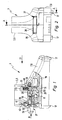
- a part of a battery-powered electric hand tool device 1 with a handle 3 of a machine housing part 5 and with a cover 7 of a battery housing part 9 can be seen.
- Cover 7 of the battery housing part 9 and handle 3 of the machine housing part 5 are connected to one another via a locking device 11.
- the battery housing part 9 is pushed over a sliding seat receptacle 10 in an operating position at the lower end of the handle 3 on the handle 3.
- a locking element 13 of the locking device 11 arranged in the handle 3 engages in a recess 15 of the cover 7 of the battery housing part 9.
- the battery housing part 9 has on the side facing away from the handle 3 joining elements 17. About this it is possible to connect the lid 7 with a lower shell of the battery housing part 9, not shown.
- grooves 19 On the handle 3 facing side of the lid 7 of the battery case part 9 grooves 19 can be seen.
- the grooves 19 are open in a receiving direction 21 and inwardly towards the inside.
- the grooves 19 are arranged on both sides of the cover 7 of the battery housing part 9 so that they form the sliding seat receptacle 10 with webs or rails 23 of the handle 3 extending in the receiving direction 21.
- the already mentioned recess 15 of the cover 7 is located on the handle 3 facing the upper side of the battery housing part 9.
- the recess 15 is bounded by an inclined first side surface 25. This is so inclined to the receiving direction 21, that the locking element 13 presses the battery housing part 9 in the sliding seat receptacle 10 in the receiving direction 21 when the battery housing part 9 is in its operating position. The locking element 13 is then under bias against the inclined side surface 25 at.
- the locking device 11 has an actuating member 27.
- the actuator 27 protrudes with a pusher 29 from an opening 30 of the handle 3 to the outside.
- a flat portion 31 connects, which is substantially disc-shaped.
- This is followed in the direction of the locking element 13, an inclined portion 33 which is inclined with respect to the receiving direction 21 in a clockwise direction.
- This inclined portion 33 passes through an opening 45 in the locking element 13
- a contact surface 35 of the inclined portion 33 of the actuator 27 contacts a contact surface 37 of the locking element 13.
- the actuator 27 is guided in the interior of the handle 3 in the sliding direction 21 longitudinally displaceable.
- the actuator 27 has a recess 39 into which a leg spring 41 engages.
- the leg spring 41 is supported with one of its legs in a receptacle 43 of the handle 3, and with its other end on the pusher 29 of the actuator 27 from. In this case, the leg spring 41 exerts a force on the actuating member 27 in the receiving direction 21 so that the pusher 29 protrudes outward from the handle 3.
- the actuator 27 engages with its inclined portion 33 in an opening 45 of the locking element 13 so that the contact surface 35 of the inclined portion 33 is in contact with the contact surface 37 of the opening 45.
- the contact surface 47 of the opening 45 is inclined with respect to the receiving direction 21.
- the locking element 13 Transverse to the receiving direction 21, the locking element 13 has a region 49 which is disposed within a compression spring 51.
- the compression spring 51 is supported with one of its ends on the locking element 13 and from its other end in a receptacle 53 of the handle 3 from.
- the receptacle 53 and the receptacle 43 are integrally formed with the handle 3 in the embodiment shown in the figures. They are designed so that on the one hand the leg spring 41 and on the other hand the compression spring 51 provide a leading receptacle.
- the compression spring 51 acts on the locking element 13 in the locking direction.
- the locking element 13 has a projecting portion 55 whose surface is inclined to cooperate with the inclined first side surface 25 of the recess 15 of the battery housing part 9.
- the battery housing part 9 is pushed in the receiving direction 21 on the handle 3.
- the webs or Rails 23 of the handle 3 in the grooves 19 of the lid 7 of the battery housing part 9 a. Grooves 19 and rails 23 thereby form the sliding seat receptacle 10th
- the locking element 13 Under the action of the compression spring 51, the locking element 13 is always loaded in the locking direction.
- the battery housing part 9 is pressed in the receiving direction 21 in the sliding seat receptacle 10. The battery housing part 9 is thus locked in the handle 3 in an operating position.
- the actuator 27 is pressed against the receiving direction 21 manually.
- the inclined portion 33 of the actuating member 27 is pushed into the opening 45 of the locking element 13. Due to the inclination of the inclined contact surfaces 35 and 37 while the locking element 13 is displaced in the unlocking, so that it is released from the recess 15 of the battery housing part.
- the projecting portion 55 of the locking element 13 is moved out of the recess 15 of the lid 7 of the battery housing part 9.
Landscapes
- Engineering & Computer Science (AREA)
- Life Sciences & Earth Sciences (AREA)
- Biophysics (AREA)
- Computer Hardware Design (AREA)
- Chemical & Material Sciences (AREA)
- Chemical Kinetics & Catalysis (AREA)
- Electrochemistry (AREA)
- General Chemical & Material Sciences (AREA)
- Mechanical Engineering (AREA)
- Battery Mounting, Suspending (AREA)
- Power Steering Mechanism (AREA)
- Portable Power Tools In General (AREA)
Abstract
Description
Die Erfindung betrifft ein akkubetriebenes Elektrohandwerkzeuggerät mit einem Maschinengehäuseteil, wobei der Akkugehäuseteil über eine Schiebesitzaufnahme in eine Betriebsposition auf das Maschinengehäuseteil aufschiebbar und über eine Verriegelungseinrichtung in dieser Betriebsposition arretierbar ist, wobei die Verriegelungseinrichtung ein manuelles Betätigungsorgan zum Lösen umfasst.The invention relates to a battery-operated electric hand tool device with a machine housing part, wherein the battery housing part via a sliding seat receptacle in an operating position on the machine housing part can be pushed and locked by a locking device in this operating position, wherein the locking device comprises a manual actuator for releasing.
Akkubetriebene Elektrohandwerkzeuggeräte sind bekannt. Sie umfassen in der Regel ein Maschinengehäuseteil und ein Akkugehäuseteil. Dazu wird das Akkugehäuseteil häufig über eine Schiebesitzaufnahme auf das Maschinengehäuseteil aufgeschoben und in einer Betriebsposition an dem Maschinengehäuseteil arretiert. Die Arretierung des Akkugehäuseteils mit dem Maschinengehäuseteil wird über eine Verriegelungseinrichtung gewährleistet. Dabei greift beispielsweise ein Rastelement des Akkugehäuseteils in eine Aufnahme des Maschinengehäuseteils so ein, dass das Akkugehäuseteil gegen ein Herausrutschen aus der Schiebesitzaufnahme gesichert ist. Es hat sich jedoch als nachteilig herausgestellt, dass bei derartigen Verriegelungen aufgrund von Fertigungstoleranzen ein Spiel zwischen den Teilen der Verriegelungseinrichtung nie ganz zu vermeiden ist und das Akkugehäuseteil in der Schiebsitzaufnahme "wackelt", was zu Geräuschen führt.Battery-operated electric hand tool devices are known. They usually include a machine housing part and a battery housing part. For this purpose, the battery housing part is often pushed over a sliding seat receptacle on the machine housing part and in an operating position on the Machine housing part locked. The locking of the battery housing part with the machine housing part is ensured by a locking device. In this case, for example, a latching element of the battery housing part engages in a receptacle of the machine housing part so that the battery housing part is secured against slipping out of the sliding seat receptacle. However, it has proved to be disadvantageous that in such locks due to manufacturing tolerances, a game between the parts of the locking device is never completely avoid and the battery housing part in the sliding seat "wobbles", which leads to noise.
Der Erfindung liegt die Aufgabe zugrunde, ein akkubetriebenes Elektrohandwerkzeuggerät vorzuschlagen, bei dem die Probleme nicht vorliegen.The invention has for its object to propose a battery-powered electric hand tool, in which the problems do not exist.
Erfindungsgemäß wird zur Lösung dieser Aufgabe ein akkubetriebenes Elektrohandwerkzeuggerät vorgeschlagen, das sich dadurch auszeichnet, dass die Verriegelungseinrichtung ein Rastelement umfasst und dem Rastelement ein erstes Federelement zugeordnet ist, welches das Rastelement in Verriegelungsrichtung vorspannt und dass dem manuellen Betätigungsorgan ein zweites Federelement zugeordnet ist, welches das Betätigungsorgan in eine unbetätigte Endstellung vorspannt.According to the invention a battery-powered electric hand tool device is proposed to solve this problem, which is characterized in that the locking device comprises a latching element and the latching element is associated with a first spring element which biases the latching element in the locking direction and that the manual actuating member is associated with a second spring element which Actuator biased in an unactuated end position.
Von besonderem Vorteil ist, dass durch die Verwendung von zwei Federelementen ein Klappern vermieden wird. Die Federelemente drücken durch die Federkraft sowohl das Betätigungsorgan als auch das Rastelement gegen einen Anschlag.It is particularly advantageous that a rattle is avoided by the use of two spring elements. The spring elements press by the spring force both the actuator and the locking element against a stop.
Dadurch wird ein Wackeln der Teile der Verriegelungseinrichtung vermieden. Durch das Vorspannen des Rastelements in Verriegelungsrichtung des Akkugehäuseteils durch das erste Federelements wird das Rastelement kraftbeaufschlagt gegen das Akkugehäuseteil gedrückt. Dadurch wird das Akkugehäuseteil kraftbeaufschlagt in die Schiebsitzaufnahme gedrückt und einem Wackeln somit vorgebeugt.As a result, a wobbling of the parts of the locking device is avoided. By biasing the locking element in the locking direction of the battery housing part by the first spring element, the locking element is subjected to force against the battery housing part. Thereby the rechargeable battery housing part is pressed into the push seat receptacle and thus prevented from wobbling.
Bei einem bevorzugten Ausführungsbeispiel des akkubetriebenen Elektrohandwerkzeuggeräts ist vorgesehen, dass die Schiebesitzaufnahme an einem Handgriff des Maschinengehäuseteils ausgebildet ist. Die Anordnung der Schiebesitzaufnahme an dem Handgriff ermöglicht es, dass das Akkugehäuseteil für den Benutzer einfach in die Betriebsposition aufschiebbar ist.In a preferred embodiment of the battery-operated electric hand tool device it is provided that the sliding seat receptacle is formed on a handle of the machine housing part. The arrangement of the sliding seat receptacle on the handle allows the battery housing part for the user is simply pushed into the operating position.
Ein weiterführendes Ausführungsbeispiel des akkubetriebenen Elektrohandwerkzeuggeräts sieht vor, dass die Schiebesitzaufnahme am unteren Ende des Handgriffs und im Wesentlichen quer zu seiner Griffachse verläuft. Vorteilhaft bei dieser Anordnung der Schiebesitzaufnahme ist, dass das Akkugehäuseteil auf den Handgriff aufschiebbar ist, während der Benutzer das Elektrohandwerkzeuggerät am Handgriff hält. Durch die Anordnung am untern Ende des Handgriffs wird ein gemeinsamer Massenschwerpunkt von Maschinengehäuseteil und Akkugehäuseteil nach unten verlagert. Dadurch ist es einem Benutzer wesentlich leichter, das akkubetriebene Elektrohandwerkzeuggerät zu führen.A further embodiment of the battery-operated electric hand tool device provides that the sliding seat receptacle extends at the lower end of the handle and substantially transversely to its handle axis. An advantage of this arrangement of the sliding seat receptacle is that the battery housing part can be pushed onto the handle while the user holds the electric hand tool device on the handle. Due to the arrangement at the lower end of the handle, a common center of gravity of the machine housing part and the battery housing part is displaced downwards. This makes it much easier for a user to run the battery-operated electric hand tool.
Es kann sich aber auch als vorteilhaft erweisen, wenn die Schiebesitzaufnahme im Wesentlichen parallel zur Griffachse verläuft, so dass das Akkugehäuse parallel zur Griffachse aufgeschoben werden kann. Es kann dabei so geformt sein, dass es in seiner Haptik die Funktion des Handgriffs unterstützt. Vorteilhaft bei diesem Ausführungsbeispiel ist, dass das akkubetriebene Elektrohandwerkzeuggerät bei dieser Kombination von Maschinengehäuseteil und Akkugehäuseteil besonders kompakt ist.However, it may also prove advantageous if the sliding seat receptacle extends substantially parallel to the handle axis, so that the battery casing can be pushed parallel to the handle axis. It can be shaped so that it supports the function of the handle in its feel. An advantage of this embodiment is that the battery-operated electric hand tool device is particularly compact in this combination of machine housing part and battery housing part.
Des Weiteren wird ein Ausführungsbeispiel des akkubetriebenen Elektrohandwerkzeuggeräts vorgeschlagen, das sich dadurch auszeichnet, dass das manuelle Betätigungsorgan und das Rastelement im Handgriff angeordnet sind. Das Akkugehäuseteil kann so besonders kompakt ausgebildet sein.Furthermore, an embodiment of the battery-operated power hand tool device is proposed, which is characterized distinguishes that the manual actuator and the locking element are arranged in the handle. The battery housing part can be designed so very compact.
Ferner wird ein Ausführungsbeispiel des akkubetriebenen Elektrohandwerkzeuggeräts vorgeschlagen, das sich dadurch auszeichnet, dass eine der Verriegelungseinrichtung in der Betriebsposition des Akkugehäuseteils zugewandte Oberseite des Akkugehäuseteils eine Ausnehmung aufweist, in welche das Rastelement im Verriegelungszustand eingreift. Vorteilhaft ist dabei, dass bei der Arretierung auf eine einfache Ausnehmung quer zur Aufschieberichtung zurückgegriffen werden kann. Die Ausnehmung kann bei einer Herstellung des Akkugehäuseteils als Spritzgussteil auf einfache Weise hergestellt werden.Furthermore, an embodiment of the battery-operated electric hand tool device is proposed, which is characterized in that one of the locking device in the operating position of the battery housing part facing top of the battery case part has a recess into which engages the locking element in the locked state. It is advantageous that can be used in the locking on a simple recess transverse to the Aufschieberichtung. The recess can be made in a production of the battery housing part as an injection molded part in a simple manner.
Ein weiteres bevorzugtes Ausführungsbeispiel des akkubetriebenen Elektrohandwerkzeuggeräts sieht vor, dass die Ausnehmung eine geneigte erste Seitenfläche aufweist. Von besonderem Vorteil ist dabei, dass das in die Aussparung eingreifende Rastelement durch Druck auf die geneigte Fläche dadurch das Akkugehäuseteil in die Schiebesitzaufnahme drückt. Damit ist gewährleistet, dass die Federkraft auf das Akkugehäuseteil so übertragen wird, dass dieses in Aufnahmerichtung in die Schiebsitzaufnahme gedrückt wird und dadurch ein Wackeln verhindert.Another preferred embodiment of the battery-operated electric hand tool device provides that the recess has an inclined first side surface. It is particularly advantageous that the locking element engaging in the recess thereby presses the battery housing part into the sliding seat receptacle by pressure on the inclined surface. This ensures that the spring force is transmitted to the battery housing part so that it is pressed in the receiving direction in the sliding seat receptacle, thereby preventing wobbling.
Ferner wird ein Ausführungsbeispiel des akkubetriebenen Elektrohandwerkzeuggeräts vorgeschlagen, das sich dadurch auszeichnet, dass das Rastelement und/oder das manuelle Betätigungsorgan Kontaktflächen aufweist, über die das Rastelement und das manuelle Betätigungsorgan einander berühren, wobei die Kontaktflächen als Keilflächen ausgebildet sind. Es ist beispielsweise denkbar das nur die Kontaktfläche des manuellen Betätigungsorgans oder nur die Kontaktfläche des Rastelements geneigt ist und auf jeweils nur einer Seitenkante des anderen aufliegt. Darüber hinaus können auch beide Kontaktflächen geneigt sein und zwar voraussichtlich derart, dass sich Betätigungsorgan und Rastelement flächig berühren. Ein besonderer Vorteil der geneigten Flächen ist, dass beispielsweise bei einer Krafteinwirkung des Betätigungsorgans auf das Rastelement eine Umlenkung der Kraft stattfindet. Durch die Kraftumlenkung ist eine Bewegung des Rastelements quer zur Stellrichtung des Betätigungsorgans möglich.Further, an embodiment of the battery-operated electric hand tool device is proposed, which is characterized in that the latching element and / or the manual actuator contact surfaces over which the latching element and the manual actuator contact each other, wherein the contact surfaces are formed as wedge surfaces. It is for example conceivable that only the contact surface of the manual actuator or only the contact surface of the locking element is inclined and rests on only one side edge of the other. In addition, both can Be inclined contact surfaces and probably so that the actuator and locking element surface contact. A particular advantage of the inclined surfaces is that, for example, upon a force of the actuator on the locking element, a deflection of the force takes place. By the force deflection is a movement of the locking element transverse to the direction of adjustment of the actuator possible.
Darüber hinaus wird ein Ausführungsbeispiel des akkubetriebenen Elektrohandwerkzeuggeräts vorgeschlagen, das sich dadurch auszeichnet, dass das Rastelement eine Öffnung aufweist, in welche das manuelle Betätigungsorgan zumindest beim Entriegeln eingreift. Darüber hinaus kann die Öffnung so vorgesehen sein, dass bei Betätigung des manuellen Betätigungsorgans die dadurch resultierende Bewegung des Rastelements quer zur Stellrichtung des Betätigungsorgans geführt wird.In addition, an embodiment of the battery-operated electric hand tool device is proposed, which is characterized in that the latching element has an opening into which engages the manual actuator, at least when unlocking. In addition, the opening may be provided so that upon actuation of the manual actuator, the resulting movement of the locking element is guided transversely to the direction of adjustment of the actuator.
Ein anderes Ausführungsbeispiel des akkubetriebenen Elektrohandwerkzeuggeräts sieht vor, dass das Maschinengehäuseteil mindestens eine Durchbrechung aufweist, durch welche das manuelle Betätigungsorgan nach Außen geführt ist. Das manuelle Betätigungsorgan kann bis zum Erreichen eines Anschlags aus der Durchbrechung herausragen. Die Bewegung des manuellen Betätigungsorgans wird dabei durch die Durchbrechung geführt.Another embodiment of the battery-operated electric hand tool device provides that the machine housing part has at least one opening through which the manual actuator is guided to the outside. The manual actuator can protrude from the opening until it reaches a stop. The movement of the manual actuator is guided through the opening.
Ferner wird ein Ausführungsbeispiel des akkubetriebenen Elektrohandwerkzeuggeräts vorgeschlagen, welches sich dadurch auszeichnet, dass das manuelle Betätigungsorgan im Wesentlichen scheibenförmig ausgebildet ist was eine einfache Herstellung bedeutet.Further, an embodiment of the battery-operated electric hand tool device is proposed, which is characterized in that the manual actuator is substantially disc-shaped, which means a simple production.
Ein weiteres Ausführungsbeispiel des akkubetriebenen Elektrohandwerkzeuggeräts sieht vor, dass das erste Federelement eine Druckfeder und/oder das zweite Federelement eine Schenkelfeder ist.Another embodiment of the battery-operated electric hand tool device provides that the first spring element is a compression spring and / or the second spring element is a leg spring.
Ferner wird ein Ausführungsbeispiel des akkubetriebenen Elektrohandwerkzeuggeräts vorgeschlagen, das sich dadurch auszeichnet, dass die Bewegungsrichtung des manuellen Betätigungsorgans im Wesentlichen quer zur Bewegungsrichtung des Rastelements verläuft.Furthermore, an embodiment of the battery-operated electric hand tool device is proposed, which is characterized in that the direction of movement of the manual actuating member extends substantially transversely to the direction of movement of the latching element.
Darüber hinaus wird ein Ausführungsbeispiel des akkubetriebenen Elektrohandwerkzeuggeräts vorgeschlagen, das sich dadurch auszeichnet, dass das Betätigungsorgan quer zu seiner Bewegungsrichtung eine Vertiefung aufweist, in welche das zweite Federelement eingreift. Vorteilhaft dabei ist, dass das zweite Federelement an der Innenseite des Handgriffs vorgesehen sein kann.In addition, an embodiment of the battery-powered electric hand tool device is proposed, which is characterized in that the actuating member transversely to its direction of movement has a recess, in which engages the second spring element. The advantage here is that the second spring element can be provided on the inside of the handle.
Ferner wird ein Ausführungsbeispiel des akkubetriebenen Elektrohandwerkzeuggeräts vorgeschlagen, welches sich dadurch auszeichnet, dass das Betätigungsorgan einen ersten im Wesentlichen ebenen Abschnitt aufweist, der in einen zweiten im Bezug auf den ersten Abschnitt geneigten Abschnitt übergeht. Vorteilhaft dabei ist, dass der geneigte zweite Abschnitt eine Keilfläche bildet, die mit dem Rastelement zusammenwirken kann. Insbesondere durch diese Ausbildung lässt sich erreichen, dass bei Entriegelung das Rastelements entgegen der Federvorspannung und damit in Entriegelungsrichtung bewegt werden kann.Furthermore, an embodiment of the battery-operated electric hand tool device is proposed, which is characterized in that the actuating member has a first substantially planar portion, which merges into a second with respect to the first portion inclined portion. The advantage here is that the inclined second portion forms a wedge surface which can cooperate with the locking element. In particular, by this training can be achieved that when unlocking the locking element against the spring preload and thus can be moved in unlocking.
Schließlich wird ein Ausführungsbeispiel des akkubetriebenen Elektrohandwerkzeuggeräts vorgeschlagen, welches sich dadurch auszeichnet, dass das Betätigungsorgan und/oder das Rastelement über Führungsmittel längsverschieblich angeordnet sind. Von Vorteil ist dabei, dass durch die nut- und federartigen Führungsmittel einem Wackeln von Betätigungsorgan und/oder Rastelement bei einer durch Krafteinwirkung, beispielsweise durch die Federelemente oder den Benutzer, geführt wird und einem Wackeln oder Schlingern im Zuge des Bewegungsvorgangs vorgebeugt wird.Finally, an embodiment of the battery-powered electric hand tool device is proposed, which is characterized in that the actuating member and / or the latching element are arranged longitudinally displaceable via guide means. The advantage here is that is guided by the nut and spring-like guide means wobbling of actuator and / or locking element at one by force, for example by the spring elements or the user, and a wobbling or rolling is prevented in the course of the movement process.
Weitere Vorteile ergeben sich aus den Unteransprüchen.Further advantages emerge from the subclaims.
Weitere Merkmale, Einzelheiten und Vorteile der Erfindung ergeben sich aus den beigefügten Patentansprüchen und aus der zeichnerischen Darstellung und nachfolgenden Beschreibung einer bevorzugten Ausführungsform des erfindungsgemäßen akkubetriebenen Elektrohandwerkzeuggeräts. In der Zeichnung zeigt:
- Figur 1
- eine perspektivische schematische durchbrochene Darstellung eines Handgriffs eines Maschinengehäuseteils und eines Deckels eines Akkugehäuseteils;
- Figur 2
- eine Aufsicht in Richtung des Pfeils II nach
Figur 1 ; - Figur 3
- eine Schnittansicht mit Schnittebene A-A gemäß
Figur 2 ; - Figur 4
- einer Schnittansicht mit Schnitteben B-B gemäß
Figur 3 .
- FIG. 1
- a perspective schematic broken view of a handle of a machine housing part and a lid of a battery housing part;
- FIG. 2
- a view in the direction of arrow II after
FIG. 1 ; - FIG. 3
- a sectional view with sectional plane AA according to
FIG. 2 ; - FIG. 4
- a sectional view with Schnittben BB according to
FIG. 3 ,
Aus den Figuren ist ein Teil eines akkubetriebenen Elektrohandwerkzeuggeräts 1 mit einem Handgriff 3 eines Maschinengehäuseteils 5 und mit einem Deckel 7 eines Akkugehäuseteils 9 ersichtlich. Deckel 7 des Akkugehäuseteils 9 und Handgriff 3 des Maschinengehäuseteils 5 sind über eine Verriegelungseinrichtung 11 miteinander verbunden. Das Akkugehäuseteil 9 ist über eine Schiebesitzaufnahme 10 in eine Betriebsposition am unteren Ende des Handgriffs 3 auf den Handgriff 3 aufgeschoben. In dieser Betriebsposition greift ein im Handgriff 3 angeordnetes Rastelement 13 der Verriegelungseinrichtung 11 in eine Ausnehmung 15 des Deckels 7 des Akkugehäuseteils 9 ein.From the figures, a part of a battery-powered electric hand tool device 1 with a handle 3 of a machine housing part 5 and with a cover 7 of a battery housing part 9 can be seen. Cover 7 of the battery housing part 9 and handle 3 of the machine housing part 5 are connected to one another via a
Das Akkugehäuseteil 9 weist auf der dem Handgriff 3 abgewandten Seite Fügeelemente 17 auf. Über diese ist es möglich, den Deckel 7 mit einer nicht dargestellten Unterschale des Akkugehäuseteils 9 zu verbinden.The battery housing part 9 has on the side facing away from the handle 3 joining
Auf der dem Handgriff 3 zugewandten Seite des Deckels 7 des Akkugehäuseteils 9 sind Nuten 19 ersichtlich. Die Nuten 19 sind in einer Aufnahmerichtung 21 und nach innen hin randoffen. Die Nuten 19 sind dabei auf beiden Seiten des Deckels 7 des Akkugehäuseteils 9 so angeordnet, so dass sie mit in Aufnahmerichtung 21 erstreckten Stegen oder Schienen 23 des Handgriffs 3 die Schiebesitzaufnahme 10 bilden.On the handle 3 facing side of the lid 7 of the battery case part 9
Die schon erwähnte Ausnehmung 15 des Deckels 7 befindet sich auf der dem Handgriff 3 zugewandten Oberseite des Akkugehäuseteils 9. Die Ausnehmung 15 ist von einer geneigten ersten Seitenfläche 25 begrenzt. Diese ist zur Aufnahmerichtung 21 so geneigt, dass das Rastelement 13 das Akkugehäuseteil 9 in der Schiebesitzaufnahme 10 in Aufnahmerichtung 21 drückt, wenn das Akkugehäuseteil 9 in seiner Betriebsposition ist. Das Rastelement 13 liegt dann unter Vorspannung gegen die geneigte Seitenfläche 25 an.The already mentioned recess 15 of the cover 7 is located on the handle 3 facing the upper side of the battery housing part 9. The recess 15 is bounded by an inclined first side surface 25. This is so inclined to the receiving
Neben dem Rastelement 13 und der Ausnehmung 15 weist die Verriegelungseinrichtung 11 ein Betätigungsorgan 27 auf. Das Betätigungsorgan 27 ragt mit einem Drücker 29 aus einer Durchbrechung 30 des Handgriffs 3 nach außen. An den Drücker 29 des Betätigungsorgans 27 schließt sich ein ebener Abschnitt 31 an, der im Wesentlichen scheibenförmig ist. Daran schließt sich in Richtung auf das Rastelement 13 ein geneigter Abschnitt 33 an, der bezüglich der Aufnahmerichtung 21 im Uhrzeigersinn geneigt ist. Dieser geneigte Abschnitt 33 durchgreift eine Öffnung 45 in dem Rastelement 13 Dabei berührt eine Kontaktfläche 35 des geneigten Abschnitts 33 des Betätigungsorgans 27 eine Kontaktfläche 37 des Rastelements 13. Das Betätigungsorgan 27 wird im Inneren des Handgriffs 3 in Aufschieberichtung 21 längsverschieblich geführt.In addition to the latching
Das Betätigungsorgan 27 weist eine Vertiefung 39 auf, in die eine Schenkelfeder 41 eingreift. Die Schenkelfeder 41 stützt sich dabei mit einem ihrer Schenkel in einer Aufnahme 43 des Handgriffs 3 ab, und mit ihrem anderen Ende am Drücker 29 des Betätigungsorgans 27 ab. Dabei übt die Schenkelfeder 41 in Aufnahmerichtung 21 eine Kraft auf das Betätigungsorgan 27 aus, so dass der Drücker 29 aus dem Handgriff 3 nach Außen vorsteht.The
Das Betätigungsorgan 27 greift mit seinem geneigten Abschnitt 33 in eine Öffnung 45 des Rastelements 13 so ein, dass die Kontaktfläche 35 des geneigten Abschnitts 33 mit der Kontaktfläche 37 der Öffnung 45 in Berührung steht. Dabei ist die Kontaktfläche 47 der Öffnung 45 bezüglich der Aufnahmerichtung 21 geneigt. Quer zur Aufnahmerichtung 21 weist das Rastelement 13 einen Bereich 49 auf, der innerhalb einer Druckfeder 51 angeordnet ist. Die Druckfeder 51 stützt sich mit einem ihrer Enden am Rastelement 13 ab und mit ihrem anderen Ende in einer Aufnahme 53 des Handgriffs 3 ab. Die Aufnahme 53 sowie die Aufnahme 43 sind bei dem in den Figuren gezeigten Ausführungsbeispiel einstückig mit dem Handgriff 3 ausgebildet. Sie sind so ausgebildet, dass sie zum einen der Schenkelfeder 41 und zum anderen der Druckfeder 51 eine führende Aufnahme bieten. Die Druckfeder 51 beaufschlagt das Rastelement 13 in Verriegelungsrichtung. An dem in Verriegelungsrichtung 21 gelegenen Ende des Rastelements 13 weist das Rastelement 13 einen vorstehenden Bereich 55 auf, dessen Oberfläche geneigt ist, um mit der geneigten ersten Seitenfläche 25 der Ausnehmung 15 des Akkugehäuseteils 9 zusammen zu wirken.The
Im Folgenden wird das Zusammenwirken der einzelnen, aus den Figuren ersichtlichen Bauteile näher beschrieben.In the following, the interaction of the individual, apparent from the figures components will be described in more detail.
Das Akkugehäuseteil 9 wird in Aufnahmerichtung 21 auf den Handgriff 3 aufgeschoben. Dabei greifen die Stege oder Schienen 23 des Handgriffs 3 in die Nuten 19 des Deckels 7 des Akkugehäuseteils 9 ein. Nuten 19 und Schienen 23 bilden dabei die Schiebesitzaufnahme 10.The battery housing part 9 is pushed in the receiving
Unter der Wirkung der Druckfeder 51 wird das Rastelement 13 stets in Verriegelungsrichtung belastet. Über das Zusammenwirken des geneigten vorstehenden Bereichs 55 und der geneigten Seitenfläche 25 des Deckels 7 des Akkugehäuseteils 9 wird das Akkugehäuseteil 9 in Aufnahmerichtung 21 in die Schiebesitzaufnahme 10 gedrückt. Das Akkugehäuseteil 9 wird also im Handgriff 3 in einer Betriebsposition arretiert.Under the action of the
Zum Lösen des Akkugehäuseteils 9 aus der Arretierung wird das Betätigungsorgan 27 entgegen der Aufnahmerichtung 21 manuell gedrückt. Bei der Verschiebung des Betätigungsorgans 27 entgegengesetzt zur Aufnahmerichtung 21 wird der geneigte Abschnitt 33 des Betätigungsorgans 27 in die Öffnung 45 des Rastelements 13 geschoben. Aufgrund der Neigung der geneigten Kontaktflächen 35 und 37 wird dabei das Rastelement 13 in Entriegelungsrichtung verschoben, so dass es aus der Ausnehmung 15 des Akkugehäuseteils freikommt. Dabei wird der vorstehende Bereich 55 des Rastelements 13 aus der Ausnehmung 15 des Deckels 7 des Akkugehäuseteils 9 herausbewegt. Sobald das Rastelement 13 außer Eingriff mit der Ausnehmung 15 ist, kann das Akkugehäuseteil 9 entgegen der Aufnahmerichtung 21 aus der Schiebesitzaufnahme vom Handgriff 3 abgezogen werden.To release the battery housing part 9 from the lock, the
Aus den Figuren geht hervor, dass sowohl im Entriegelungs- als auch im Verriegelungszustand die einzelnen Elemente der Verriegelungseinrichtung 11 durch die beiden Federn 41 und 51 mit Kraft beaufschlagt sind. Sie werden gegen eine Endstellung gedrückt und liegen daher spielfrei an. Dadurch wird einem Wackeln oder Klappern der einzelnen Elemente vorgebeugt. Aus den Figuren geht weiterhin hervor, dass das Akkugehäuseteil 9 durch die Druckfeder 51 mit Kraft beaufschlagt gegen eine Endstellung/Anschlag mit dem Handgriff 3 gehalten wird. Dies hat zur Folge, dass das Akkugehäuseteil 9 und der Handgriff 3 fest und ohne zu wackeln lösbar miteinander verbunden sind.From the figures shows that both in the unlocking and in the locking state, the individual elements of the
Claims (16)
Priority Applications (4)
| Application Number | Priority Date | Filing Date | Title |
|---|---|---|---|
| ES07011089T ES2333269T3 (en) | 2007-06-06 | 2007-06-06 | MANUAL ELECTRIC TOOL MACHINE POWERED BY BATTERY. |
| EP07011089A EP2000266B1 (en) | 2007-06-06 | 2007-06-06 | Battery-driven electric machine tool |
| DE502007001912T DE502007001912D1 (en) | 2007-06-06 | 2007-06-06 | Battery operated electric hand tool |
| AT07011089T ATE447466T1 (en) | 2007-06-06 | 2007-06-06 | BATTERY POWERED ELECTRIC HAND TOOL |
Applications Claiming Priority (1)
| Application Number | Priority Date | Filing Date | Title |
|---|---|---|---|
| EP07011089A EP2000266B1 (en) | 2007-06-06 | 2007-06-06 | Battery-driven electric machine tool |
Publications (2)
| Publication Number | Publication Date |
|---|---|
| EP2000266A1 true EP2000266A1 (en) | 2008-12-10 |
| EP2000266B1 EP2000266B1 (en) | 2009-11-04 |
Family
ID=38222096
Family Applications (1)
| Application Number | Title | Priority Date | Filing Date |
|---|---|---|---|
| EP07011089A Active EP2000266B1 (en) | 2007-06-06 | 2007-06-06 | Battery-driven electric machine tool |
Country Status (4)
| Country | Link |
|---|---|
| EP (1) | EP2000266B1 (en) |
| AT (1) | ATE447466T1 (en) |
| DE (1) | DE502007001912D1 (en) |
| ES (1) | ES2333269T3 (en) |
Cited By (1)
| Publication number | Priority date | Publication date | Assignee | Title |
|---|---|---|---|---|
| US11539163B2 (en) | 2019-03-12 | 2022-12-27 | Milwaukee Electric Tool Corporation | Electric device including a housing for receiving a battery pack and a latching mechanism |
Families Citing this family (1)
| Publication number | Priority date | Publication date | Assignee | Title |
|---|---|---|---|---|
| EP2875910B1 (en) | 2013-10-15 | 2016-06-08 | Sparky Eltos Ad | Device for locking the batteries of an electric tool |
Citations (4)
| Publication number | Priority date | Publication date | Assignee | Title |
|---|---|---|---|---|
| GB2303018A (en) * | 1995-06-30 | 1997-02-05 | Nec Corp | Battery case mounting mechanism incorporates electrical contacts |
| EP1463274A1 (en) * | 2003-03-25 | 2004-09-29 | LG Electronics Inc. | Locking mechanism |
| EP1683608A1 (en) * | 2005-01-24 | 2006-07-26 | Techtronic Industries Co., Ltd. | Slide type battery ejection mechanism |
| EP1744386A2 (en) * | 2001-11-09 | 2007-01-17 | Milwaukee Electric Tool Corporation | Combination device comprising a radio, audio device and battery charger. |
-
2007
- 2007-06-06 DE DE502007001912T patent/DE502007001912D1/en active Active
- 2007-06-06 EP EP07011089A patent/EP2000266B1/en active Active
- 2007-06-06 ES ES07011089T patent/ES2333269T3/en active Active
- 2007-06-06 AT AT07011089T patent/ATE447466T1/en active
Patent Citations (4)
| Publication number | Priority date | Publication date | Assignee | Title |
|---|---|---|---|---|
| GB2303018A (en) * | 1995-06-30 | 1997-02-05 | Nec Corp | Battery case mounting mechanism incorporates electrical contacts |
| EP1744386A2 (en) * | 2001-11-09 | 2007-01-17 | Milwaukee Electric Tool Corporation | Combination device comprising a radio, audio device and battery charger. |
| EP1463274A1 (en) * | 2003-03-25 | 2004-09-29 | LG Electronics Inc. | Locking mechanism |
| EP1683608A1 (en) * | 2005-01-24 | 2006-07-26 | Techtronic Industries Co., Ltd. | Slide type battery ejection mechanism |
Cited By (1)
| Publication number | Priority date | Publication date | Assignee | Title |
|---|---|---|---|---|
| US11539163B2 (en) | 2019-03-12 | 2022-12-27 | Milwaukee Electric Tool Corporation | Electric device including a housing for receiving a battery pack and a latching mechanism |
Also Published As
| Publication number | Publication date |
|---|---|
| ATE447466T1 (en) | 2009-11-15 |
| ES2333269T3 (en) | 2010-02-18 |
| EP2000266B1 (en) | 2009-11-04 |
| DE502007001912D1 (en) | 2009-12-17 |
Similar Documents
| Publication | Publication Date | Title |
|---|---|---|
| DE3878927T2 (en) | JIGSAW. | |
| DE2355497C2 (en) | Buckle for seat belts | |
| EP2627208B1 (en) | Buckle | |
| DE102005044445A1 (en) | Screwdriver for bone-screws, has grip section and shaft whose free end has rounded-off cross section and insertable in rounded-off receiver opening in head of bone-screw | |
| DE102006009976A1 (en) | Radial adjustment mechanism for use in vehicle seat assembly has pawl forming pawl axis is movably arranged between guides on one disk element with outer end with toothed segment that can lock into teeth on other disk element | |
| EP1491295B1 (en) | Locking pin for fixing a tool member to a hydraulic pressing tool | |
| EP2643536B1 (en) | Mechanical or mechatronical actuatable locking system | |
| EP2245963A1 (en) | Connecting device | |
| EP3565979A1 (en) | Fastening assembly and a corresponding switch cabinet housing | |
| EP2000266B1 (en) | Battery-driven electric machine tool | |
| EP2792822B1 (en) | Coding via blocking bar | |
| WO2012104056A1 (en) | Medical appliance | |
| DE10201242A1 (en) | Locking system for drawer comprises L-shaped spring which fits on corner of the drawer and is held in place by clamping strip supported by retaining strip released by drawer handle | |
| DE19928729B4 (en) | Window handle lock | |
| DE202009007599U1 (en) | Battery operated electric hand tool | |
| EP1249570A1 (en) | Closure device | |
| EP3686908A1 (en) | Electrical installation apparatus comprising a base | |
| EP2354386B1 (en) | Safety latch device | |
| DE60101974T2 (en) | Key with metal shaft and plastic head, provided with a locking box | |
| EP2056318A1 (en) | Switch, in particular window lifting switch | |
| EP3754680B1 (en) | Switch device for a cooking appliance with a cooking chamber and cooking appliance closable by a door | |
| WO2003013375A1 (en) | Medical instrument having two parts with a joining device for joining them | |
| EP1174892A2 (en) | Mechanical locking device for on- and off-position of an electrical push switch | |
| AT389915B (en) | LOCK WITH SELF-TENSIONING NUT | |
| DE102005007225B4 (en) | Cover for fuse switch disconnector with adjustable handle |
Legal Events
| Date | Code | Title | Description |
|---|---|---|---|
| PUAI | Public reference made under article 153(3) epc to a published international application that has entered the european phase |
Free format text: ORIGINAL CODE: 0009012 |
|
| AK | Designated contracting states |
Kind code of ref document: A1 Designated state(s): AT BE BG CH CY CZ DE DK EE ES FI FR GB GR HU IE IS IT LI LT LU LV MC MT NL PL PT RO SE SI SK TR |
|
| AX | Request for extension of the european patent |
Extension state: AL BA HR MK RS |
|
| 17P | Request for examination filed |
Effective date: 20090319 |
|
| RIN1 | Information on inventor provided before grant (corrected) |
Inventor name: CONG, PHAM Inventor name: SCHWARZ, STEFAN, DIPL.ING.(FH) Inventor name: DAESCHLER, ARTTU Inventor name: FISCHER, WERNER |
|
| GRAP | Despatch of communication of intention to grant a patent |
Free format text: ORIGINAL CODE: EPIDOSNIGR1 |
|
| AKX | Designation fees paid |
Designated state(s): AT BE BG CH CY CZ DE DK EE ES FI FR GB GR HU IE IS IT LI LT LU LV MC MT NL PL PT RO SE SI SK TR |
|
| GRAS | Grant fee paid |
Free format text: ORIGINAL CODE: EPIDOSNIGR3 |
|
| GRAA | (expected) grant |
Free format text: ORIGINAL CODE: 0009210 |
|
| AK | Designated contracting states |
Kind code of ref document: B1 Designated state(s): AT BE BG CH CY CZ DE DK EE ES FI FR GB GR HU IE IS IT LI LT LU LV MC MT NL PL PT RO SE SI SK TR |
|
| REG | Reference to a national code |
Ref country code: GB Ref legal event code: FG4D Free format text: NOT ENGLISH |
|
| REG | Reference to a national code |
Ref country code: CH Ref legal event code: EP |
|
| REG | Reference to a national code |
Ref country code: IE Ref legal event code: FG4D |
|
| REF | Corresponds to: |
Ref document number: 502007001912 Country of ref document: DE Date of ref document: 20091217 Kind code of ref document: P |
|
| REG | Reference to a national code |
Ref country code: ES Ref legal event code: FG2A Ref document number: 2333269 Country of ref document: ES Kind code of ref document: T3 |
|
| LTIE | Lt: invalidation of european patent or patent extension |
Effective date: 20091104 |
|
| PG25 | Lapsed in a contracting state [announced via postgrant information from national office to epo] |
Ref country code: PT Free format text: LAPSE BECAUSE OF FAILURE TO SUBMIT A TRANSLATION OF THE DESCRIPTION OR TO PAY THE FEE WITHIN THE PRESCRIBED TIME-LIMIT Effective date: 20100304 Ref country code: SE Free format text: LAPSE BECAUSE OF FAILURE TO SUBMIT A TRANSLATION OF THE DESCRIPTION OR TO PAY THE FEE WITHIN THE PRESCRIBED TIME-LIMIT Effective date: 20091104 Ref country code: LT Free format text: LAPSE BECAUSE OF FAILURE TO SUBMIT A TRANSLATION OF THE DESCRIPTION OR TO PAY THE FEE WITHIN THE PRESCRIBED TIME-LIMIT Effective date: 20091104 Ref country code: IS Free format text: LAPSE BECAUSE OF FAILURE TO SUBMIT A TRANSLATION OF THE DESCRIPTION OR TO PAY THE FEE WITHIN THE PRESCRIBED TIME-LIMIT Effective date: 20100304 Ref country code: FI Free format text: LAPSE BECAUSE OF FAILURE TO SUBMIT A TRANSLATION OF THE DESCRIPTION OR TO PAY THE FEE WITHIN THE PRESCRIBED TIME-LIMIT Effective date: 20091104 |
|
| REG | Reference to a national code |
Ref country code: IE Ref legal event code: FD4D |
|
| PG25 | Lapsed in a contracting state [announced via postgrant information from national office to epo] |
Ref country code: CY Free format text: LAPSE BECAUSE OF FAILURE TO SUBMIT A TRANSLATION OF THE DESCRIPTION OR TO PAY THE FEE WITHIN THE PRESCRIBED TIME-LIMIT Effective date: 20091104 Ref country code: SI Free format text: LAPSE BECAUSE OF FAILURE TO SUBMIT A TRANSLATION OF THE DESCRIPTION OR TO PAY THE FEE WITHIN THE PRESCRIBED TIME-LIMIT Effective date: 20091104 Ref country code: LV Free format text: LAPSE BECAUSE OF FAILURE TO SUBMIT A TRANSLATION OF THE DESCRIPTION OR TO PAY THE FEE WITHIN THE PRESCRIBED TIME-LIMIT Effective date: 20091104 Ref country code: PL Free format text: LAPSE BECAUSE OF FAILURE TO SUBMIT A TRANSLATION OF THE DESCRIPTION OR TO PAY THE FEE WITHIN THE PRESCRIBED TIME-LIMIT Effective date: 20091104 |
|
| PG25 | Lapsed in a contracting state [announced via postgrant information from national office to epo] |
Ref country code: EE Free format text: LAPSE BECAUSE OF FAILURE TO SUBMIT A TRANSLATION OF THE DESCRIPTION OR TO PAY THE FEE WITHIN THE PRESCRIBED TIME-LIMIT Effective date: 20091104 Ref country code: RO Free format text: LAPSE BECAUSE OF FAILURE TO SUBMIT A TRANSLATION OF THE DESCRIPTION OR TO PAY THE FEE WITHIN THE PRESCRIBED TIME-LIMIT Effective date: 20091104 Ref country code: IE Free format text: LAPSE BECAUSE OF FAILURE TO SUBMIT A TRANSLATION OF THE DESCRIPTION OR TO PAY THE FEE WITHIN THE PRESCRIBED TIME-LIMIT Effective date: 20091104 Ref country code: BG Free format text: LAPSE BECAUSE OF FAILURE TO SUBMIT A TRANSLATION OF THE DESCRIPTION OR TO PAY THE FEE WITHIN THE PRESCRIBED TIME-LIMIT Effective date: 20100204 Ref country code: DK Free format text: LAPSE BECAUSE OF FAILURE TO SUBMIT A TRANSLATION OF THE DESCRIPTION OR TO PAY THE FEE WITHIN THE PRESCRIBED TIME-LIMIT Effective date: 20091104 |
|
| PG25 | Lapsed in a contracting state [announced via postgrant information from national office to epo] |
Ref country code: SK Free format text: LAPSE BECAUSE OF FAILURE TO SUBMIT A TRANSLATION OF THE DESCRIPTION OR TO PAY THE FEE WITHIN THE PRESCRIBED TIME-LIMIT Effective date: 20091104 Ref country code: CZ Free format text: LAPSE BECAUSE OF FAILURE TO SUBMIT A TRANSLATION OF THE DESCRIPTION OR TO PAY THE FEE WITHIN THE PRESCRIBED TIME-LIMIT Effective date: 20091104 |
|
| PLBE | No opposition filed within time limit |
Free format text: ORIGINAL CODE: 0009261 |
|
| STAA | Information on the status of an ep patent application or granted ep patent |
Free format text: STATUS: NO OPPOSITION FILED WITHIN TIME LIMIT |
|
| 26N | No opposition filed |
Effective date: 20100805 |
|
| PG25 | Lapsed in a contracting state [announced via postgrant information from national office to epo] |
Ref country code: GR Free format text: LAPSE BECAUSE OF FAILURE TO SUBMIT A TRANSLATION OF THE DESCRIPTION OR TO PAY THE FEE WITHIN THE PRESCRIBED TIME-LIMIT Effective date: 20100205 |
|
| BERE | Be: lapsed |
Owner name: METABOWERKE G.M.B.H. Effective date: 20100630 |
|
| REG | Reference to a national code |
Ref country code: NL Ref legal event code: V1 Effective date: 20110101 |
|
| PG25 | Lapsed in a contracting state [announced via postgrant information from national office to epo] |
Ref country code: MC Free format text: LAPSE BECAUSE OF NON-PAYMENT OF DUE FEES Effective date: 20100630 |
|
| PG25 | Lapsed in a contracting state [announced via postgrant information from national office to epo] |
Ref country code: MT Free format text: LAPSE BECAUSE OF FAILURE TO SUBMIT A TRANSLATION OF THE DESCRIPTION OR TO PAY THE FEE WITHIN THE PRESCRIBED TIME-LIMIT Effective date: 20091104 |
|
| PG25 | Lapsed in a contracting state [announced via postgrant information from national office to epo] |
Ref country code: NL Free format text: LAPSE BECAUSE OF NON-PAYMENT OF DUE FEES Effective date: 20110101 |
|
| PG25 | Lapsed in a contracting state [announced via postgrant information from national office to epo] |
Ref country code: BE Free format text: LAPSE BECAUSE OF NON-PAYMENT OF DUE FEES Effective date: 20100630 |
|
| REG | Reference to a national code |
Ref country code: ES Ref legal event code: FD2A Effective date: 20110715 |
|
| PG25 | Lapsed in a contracting state [announced via postgrant information from national office to epo] |
Ref country code: ES Free format text: LAPSE BECAUSE OF NON-PAYMENT OF DUE FEES Effective date: 20110705 |
|
| PG25 | Lapsed in a contracting state [announced via postgrant information from national office to epo] |
Ref country code: ES Free format text: LAPSE BECAUSE OF NON-PAYMENT OF DUE FEES Effective date: 20100607 |
|
| PGFP | Annual fee paid to national office [announced via postgrant information from national office to epo] |
Ref country code: CH Payment date: 20120622 Year of fee payment: 6 |
|
| PG25 | Lapsed in a contracting state [announced via postgrant information from national office to epo] |
Ref country code: HU Free format text: LAPSE BECAUSE OF FAILURE TO SUBMIT A TRANSLATION OF THE DESCRIPTION OR TO PAY THE FEE WITHIN THE PRESCRIBED TIME-LIMIT Effective date: 20100505 Ref country code: LU Free format text: LAPSE BECAUSE OF NON-PAYMENT OF DUE FEES Effective date: 20100606 |
|
| PG25 | Lapsed in a contracting state [announced via postgrant information from national office to epo] |
Ref country code: TR Free format text: LAPSE BECAUSE OF FAILURE TO SUBMIT A TRANSLATION OF THE DESCRIPTION OR TO PAY THE FEE WITHIN THE PRESCRIBED TIME-LIMIT Effective date: 20091104 |
|
| PGFP | Annual fee paid to national office [announced via postgrant information from national office to epo] |
Ref country code: AT Payment date: 20120620 Year of fee payment: 6 |
|
| REG | Reference to a national code |
Ref country code: CH Ref legal event code: PL |
|
| REG | Reference to a national code |
Ref country code: AT Ref legal event code: MM01 Ref document number: 447466 Country of ref document: AT Kind code of ref document: T Effective date: 20130606 |
|
| PG25 | Lapsed in a contracting state [announced via postgrant information from national office to epo] |
Ref country code: LI Free format text: LAPSE BECAUSE OF NON-PAYMENT OF DUE FEES Effective date: 20130630 Ref country code: CH Free format text: LAPSE BECAUSE OF NON-PAYMENT OF DUE FEES Effective date: 20130630 |
|
| PG25 | Lapsed in a contracting state [announced via postgrant information from national office to epo] |
Ref country code: AT Free format text: LAPSE BECAUSE OF NON-PAYMENT OF DUE FEES Effective date: 20130606 |
|
| REG | Reference to a national code |
Ref country code: DE Ref legal event code: R082 Ref document number: 502007001912 Country of ref document: DE Representative=s name: LORENZ & KOLLEGEN PATENTANWAELTE PARTNERSCHAFT, DE |
|
| REG | Reference to a national code |
Ref country code: FR Ref legal event code: PLFP Year of fee payment: 10 |
|
| REG | Reference to a national code |
Ref country code: FR Ref legal event code: PLFP Year of fee payment: 11 |
|
| REG | Reference to a national code |
Ref country code: FR Ref legal event code: PLFP Year of fee payment: 12 |
|
| PGFP | Annual fee paid to national office [announced via postgrant information from national office to epo] |
Ref country code: IT Payment date: 20210630 Year of fee payment: 15 Ref country code: FR Payment date: 20210621 Year of fee payment: 15 |
|
| PGFP | Annual fee paid to national office [announced via postgrant information from national office to epo] |
Ref country code: GB Payment date: 20210623 Year of fee payment: 15 |
|
| GBPC | Gb: european patent ceased through non-payment of renewal fee |
Effective date: 20220606 |
|
| PG25 | Lapsed in a contracting state [announced via postgrant information from national office to epo] |
Ref country code: FR Free format text: LAPSE BECAUSE OF NON-PAYMENT OF DUE FEES Effective date: 20220630 |
|
| PG25 | Lapsed in a contracting state [announced via postgrant information from national office to epo] |
Ref country code: GB Free format text: LAPSE BECAUSE OF NON-PAYMENT OF DUE FEES Effective date: 20220606 |
|
| PGFP | Annual fee paid to national office [announced via postgrant information from national office to epo] |
Ref country code: DE Payment date: 20230620 Year of fee payment: 17 |