EP2000263A1 - Vorrichtung zum Herausziehen des Hochdruckpumpenantriebsrads in einem Fahrzeug - Google Patents
Vorrichtung zum Herausziehen des Hochdruckpumpenantriebsrads in einem Fahrzeug Download PDFInfo
- Publication number
- EP2000263A1 EP2000263A1 EP08157013A EP08157013A EP2000263A1 EP 2000263 A1 EP2000263 A1 EP 2000263A1 EP 08157013 A EP08157013 A EP 08157013A EP 08157013 A EP08157013 A EP 08157013A EP 2000263 A1 EP2000263 A1 EP 2000263A1
- Authority
- EP
- European Patent Office
- Prior art keywords
- pulley
- sleeve
- axially
- nut
- pressure pump
- Prior art date
- Legal status (The legal status is an assumption and is not a legal conclusion. Google has not performed a legal analysis and makes no representation as to the accuracy of the status listed.)
- Withdrawn
Links
Images
Classifications
-
- B—PERFORMING OPERATIONS; TRANSPORTING
- B25—HAND TOOLS; PORTABLE POWER-DRIVEN TOOLS; MANIPULATORS
- B25B—TOOLS OR BENCH DEVICES NOT OTHERWISE PROVIDED FOR, FOR FASTENING, CONNECTING, DISENGAGING, OR HOLDING
- B25B27/00—Hand tools, specially adapted for fitting together or separating parts or objects whether or not involving some deformation, not otherwise provided for
- B25B27/02—Hand tools, specially adapted for fitting together or separating parts or objects whether or not involving some deformation, not otherwise provided for for connecting objects by press fit or detaching same
- B25B27/023—Hand tools, specially adapted for fitting together or separating parts or objects whether or not involving some deformation, not otherwise provided for for connecting objects by press fit or detaching same using screws
Definitions
- the present invention relates to a device for extracting the high-pressure pump pulley in a vehicle, in particular in a motor vehicle. It also relates to a method for extracting the high pressure pump pulley in a vehicle, which uses such a device.
- the need to make tapped bores in the pulley is an obstacle to the need for speed and simplicity that must present a service intervention.
- an outboard motor support bearing or bearing support which comprises a bell-shaped extraction block, the large end surface of which is provided with a plurality of concentric grooves.
- the grooves allow selective engagement around a peripheral edge defining an opening around the propeller shaft in the lower module of the engine.
- An elongate, externally threaded sleeve extends through the bell-shaped extraction block. The inner end of the sleeve is placed place against the center of thrust of the propeller shaft and a nut is screwed on the sleeve outside the smallest outer end of the extraction block.
- a thrust washer is interposed between the nut and the extraction block.
- a ring-shaped member is attached to the sleeve by means of a plurality of fixing screws and an elongate handle extends radially outwardly from the shaped member. ring to a stop position against an upper portion of the motor housing.
- the threaded end portion of the propeller shaft extends outwardly from the sleeve and the sleeve is attached to the outer end of the propeller shaft by a washer and nut assembly mounted on the threaded end portion.
- a suitable key is engaged on the sleeve nut, and is then turned clockwise.
- the elongate handle locks against the lower motor housing housing, leaving only the possibility of axial movement to the threaded sleeve, thereby removing the propeller shaft, bearing support, and gear. reverse of their attachment in the housing.
- Such an extractor is relatively complex in design, and does not apply to the extraction of the pulley of a high pressure pump in a vehicle.
- the object of the present invention is to provide a device for extracting the high-pressure pump pulley in a vehicle, in particular in a motor vehicle, which makes it possible, in particular in after-sales service, a simple and rapid extraction, and consequently economic, pulley.
- Another object of the present invention is to provide such a device, which allows to move from the conventional tooth 33 to a 22-tooth pulley without having problems disassembly.
- the present invention provides a novel device for extracting the pulley from high pressure pump in a vehicle, the pulley being mounted on the drive shaft of the high pressure pump and immobilized axially on the latter by a flange nut, which device is constituted by a sleeve, generally cylindrical in shape, mounted concentrically on the base of the nut and the hub of the pulley, which axially secures the flange nut and the pulley, the unscrewing movement of the flange nut causing the disengagement of the pulley from the drive shaft of the high pressure pump and thus allowing the extraction of the pulley.
- the sleeve comprises an internal shoulder axially locking the flange nut and means for axially locking the pulley against the flange nut, so as to axially secure the pulley, the sleeve and the flange nut.
- the locking means of the pulley against the flange nut are constituted by at least one radial shoulder of the hub of the pulley and at least one arm of the sleeve which axially surrounds said shoulder. radial to axially immobilize the pulley relative to the sleeve.
- said radial shoulder at least of the hub of the pulley is constituted by a portion of the perforated radial connection structure which connects the hub to the peripheral ring of the carrier pulley of the toothing.
- Each arm is an integral part of the sleeve and has a generally arcuate shape.
- each arm of the sleeve is substantially close to the angular dimension of said radial shoulder that the arm comes to "grip" to axially immobilize the pulley relative to the sleeve.
- the hub of the pulley there are two radial shoulders of the hub of the pulley which cooperate with two arms of the sleeve in order to axially immobilize the pulley with respect to the sleeve.
- the two arms of the sleeve are located symmetrically with respect to the center of the sleeve and the two radial shoulders are located symmetrically with respect to the center of the hub of the pulley.
- the hub of the pulley is advantageously mounted on the drive shaft of the high pressure pump by conical surface assembly.
- the pulley of the high pressure pump is a pulley of 22 teeth.
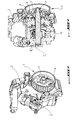
- a high pressure pump of general reference 1, mounted on a pump support 2 connected to the frame of the vehicle not shown.
- the pulley of the high pressure pump is a conventional pulley, referenced 3, with a peripheral toothing of 33 teeth designated by the reference 6.
- the pulley 3 comprises a hub 7 immobilized axially on the drive shaft 5 of the high pressure pump 1 by a flange nut 4 mounted on the end of the drive shaft 5.
- the hub 7 is connected to the peripheral toothing 6 by a perforated radial connection structure 8.
- the assembly of the hub 7 of the pulley 3 on the drive shaft 5 of the high pressure pump 1 is a conical surface assembly, namely an inner conical surface of the hub 7 and a corresponding conical surface of the drive shaft 5.
- the conical surface assembly blocks the pulley 3 on the drive shaft 5 and makes as a result, the latter integral in rotation.
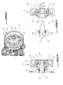
- the extraction of the pulley 3 from the high-pressure pump 1 is obtained by means of an extractor 10 and two screws 9.
- the extractor 10 is put in place on the radial connection structure 8 of the pulley 3 from the outside of the pulley 3 ( figure 3 , more particularly) and is fixed by mounting the two screws 9 in corresponding threaded holes machined in the radial connection structure 8.
- the assembly formed by the pulley 3, the extractor 10 and the two screws 9 is a set made secured by screwing the screws 9.
- the new device for extracting the pump pulley makes it possible to disassemble the pulley 3 without resorting to the machining of threaded bores; this makes it possible to disassemble the pulley, particularly after-sales, in a simpler and faster way, and therefore more economical.
- the extraction device according to the present invention, described below makes it possible to go from a 33-tooth pulley to a 22-tooth pulley without having disassembly problems.
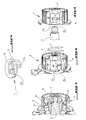
- the device for extracting the pulley is constituted by a sleeve, of general reference 11 ( figure 6 , more particularly), which comprises a main portion 11a, of generally cylindrical shape, with an internal shoulder 11c, and two arms 11b, "monoblocks" with the main portion 11a, generally in the shape of peripheral arcs offset axially by relative to the main part 11a, whose function is specified below in the description of the extraction process according to the invention.
- a first step of the extraction method according to the invention consists in putting in place from outside the sleeve 11 on the periphery of the base 4a of the nut 4 and the periphery of at least one radial shoulder 8a of the hub 7 adjacent to the base 4a in the axial direction of the pulley.
- the radial shoulder 8a is an integral part of the openwork radial connection structure 8 which connects the hub 7 to the peripheral toothing 6.
- the arms 11b of the sleeve 11 have an angular dimension sufficiently small to allow them to pass axially through the openings of the structure Opened radial connection 8.
- Each arm 11b of the sleeve 11 in position "grips" a radial shoulder 8a.
- the sleeve 11, placed in position axially secures the flange nut 4, the pulley 3 and the sleeve 11.
- the second step of the extraction process of the invention consists in unscrewing the flange nut 4 (arrow F from the figure 8 ).
Landscapes
- Engineering & Computer Science (AREA)
- Mechanical Engineering (AREA)
- Pulleys (AREA)
Applications Claiming Priority (1)
| Application Number | Priority Date | Filing Date | Title |
|---|---|---|---|
| FR0755489A FR2916996B1 (fr) | 2007-06-05 | 2007-06-05 | Dispositif pour extraire la poulie de pompe haute pression dans un vehicule. |
Publications (1)
| Publication Number | Publication Date |
|---|---|
| EP2000263A1 true EP2000263A1 (de) | 2008-12-10 |
Family
ID=38829624
Family Applications (1)
| Application Number | Title | Priority Date | Filing Date |
|---|---|---|---|
| EP08157013A Withdrawn EP2000263A1 (de) | 2007-06-05 | 2008-05-27 | Vorrichtung zum Herausziehen des Hochdruckpumpenantriebsrads in einem Fahrzeug |
Country Status (2)
| Country | Link |
|---|---|
| EP (1) | EP2000263A1 (de) |
| FR (1) | FR2916996B1 (de) |
Families Citing this family (1)
| Publication number | Priority date | Publication date | Assignee | Title |
|---|---|---|---|---|
| DE102012106302B3 (de) * | 2012-07-12 | 2014-02-27 | Model Research International Co., Ltd. | Vorrichtung zum Entfernen eines Metallservohorns mit Keilwellenkupplung |
Citations (6)
| Publication number | Priority date | Publication date | Assignee | Title |
|---|---|---|---|---|
| US4236291A (en) | 1979-08-20 | 1980-12-02 | Barrow Randall G | Bearing carrier puller for outboard motors |
| US4864709A (en) * | 1986-03-25 | 1989-09-12 | Klucz Francis M | Tools for pulling propellers and bearing carriers from outboard units |
| DE10043980C1 (de) * | 2000-09-05 | 2002-04-04 | Klann Tools Ltd | Vorrichtung zum Austauschen von Zahnriemenscheiben an Kraftfahrzeugmotoren |
| US20030085571A1 (en) * | 2001-11-08 | 2003-05-08 | Avery Richard D | Waste removal conduit attachment for use with mobile sewage units |
| WO2004082887A1 (en) * | 2003-03-19 | 2004-09-30 | Glen Robert Duffy | A harmonic balancer puller |
| DE102004012817A1 (de) * | 2004-03-16 | 2005-10-06 | Wolf Gmbh | Rohrverbindungselement |
-
2007
- 2007-06-05 FR FR0755489A patent/FR2916996B1/fr not_active Expired - Fee Related
-
2008
- 2008-05-27 EP EP08157013A patent/EP2000263A1/de not_active Withdrawn
Patent Citations (6)
| Publication number | Priority date | Publication date | Assignee | Title |
|---|---|---|---|---|
| US4236291A (en) | 1979-08-20 | 1980-12-02 | Barrow Randall G | Bearing carrier puller for outboard motors |
| US4864709A (en) * | 1986-03-25 | 1989-09-12 | Klucz Francis M | Tools for pulling propellers and bearing carriers from outboard units |
| DE10043980C1 (de) * | 2000-09-05 | 2002-04-04 | Klann Tools Ltd | Vorrichtung zum Austauschen von Zahnriemenscheiben an Kraftfahrzeugmotoren |
| US20030085571A1 (en) * | 2001-11-08 | 2003-05-08 | Avery Richard D | Waste removal conduit attachment for use with mobile sewage units |
| WO2004082887A1 (en) * | 2003-03-19 | 2004-09-30 | Glen Robert Duffy | A harmonic balancer puller |
| DE102004012817A1 (de) * | 2004-03-16 | 2005-10-06 | Wolf Gmbh | Rohrverbindungselement |
Non-Patent Citations (1)
| Title |
|---|
| "Lift button retention device", IBM TECHNICAL DISCLOSURE BULLETIN, vol. 28, no. 9, February 1986 (1986-02-01), Armonk, New York, USA, XP001600589 * |
Also Published As
| Publication number | Publication date |
|---|---|
| FR2916996A1 (fr) | 2008-12-12 |
| FR2916996B1 (fr) | 2010-01-15 |
Similar Documents
| Publication | Publication Date | Title |
|---|---|---|
| CA2830575C (fr) | Dispositif d'obturation a verrouillage auto-activable | |
| EP2435302B1 (de) | Verstellvorrichtung der propellerblätter eines turbofantriebwerks mittels festem stellglied | |
| EP2435303B1 (de) | Verstellvorrichtung der propellerblätter eines turbofantriebwerks mittels samt den propellerblättern rotierendem stellglied | |
| EP2678531B1 (de) | Fanrotor und zugehöriges Turbostrahltriebwerk | |
| EP1472475B9 (de) | Differential für fahrzeuge | |
| EP3090182B1 (de) | Hydraulisches system mit abflussgehäuse | |
| FR2992677A1 (fr) | Moyeu pour logement radial d'anneau d'helice de turbomachine a pales a calage variable et assemblage comportant un tel moyeu | |
| FR2801647A1 (fr) | Dispositif de fixation d'une helice de ventilateur sur un arbre moteur | |
| WO2013060986A1 (fr) | Pressoir a pressage par vis | |
| FR2535257A1 (fr) | Moyeu a roue a reducteur integre | |
| EP3173326B1 (de) | Lager eines schaufelfusses, und sein herstellungsverfahren, system, schwingungs- und drehsystem, das ein solches lager umfasst | |
| EP3029355B1 (de) | Spannrolle | |
| EP0052547B1 (de) | Vorrichtung zum Montieren und Auswuchten der rotierenden Messer einer Kuttermaschine | |
| FR2916996A1 (fr) | Dispositif pour extraire la poulie de pompe haute pression dans un vehicule. | |
| EP2462361B1 (de) | Vorspannungsvorrichtung mit radialer aktivität | |
| FR2949138A1 (fr) | Turbomachine comportant des moyens d'anti-rotation d'un ecrou de palier | |
| EP3478954B1 (de) | Nockenwellenhalter mit lagerdeckeln mit einem gebohrten ölkanal | |
| EP3756994A1 (de) | Vorschubpropeller, der mit auswechselbaren schraubenblättern ausgestattet ist, und montageverfahren für auswechselbare schraubenblätter auf einem vorschubpropeller | |
| EP2932934B1 (de) | Vorrichtung zur zentrifugalablenkung für chirurgisches oder zahntechnisches handstück, das die entfernung von fremdkörpern ermöglicht | |
| FR2943098A1 (fr) | Dispositif de fixation de deux pieces annulaires coaxiales dans une turbomachine | |
| FR3126961A1 (fr) | Helice pour une turbomachine d’aeronef | |
| EP2110573A1 (de) | Vorrichtung zur Schnelldemontage der kompletten Blockiervorrichtung auf der Welle einer Riemenscheibe | |
| EP2420707B1 (de) | Einheit für ein Lenksystem eines Fahrzeugs | |
| EP3929412B1 (de) | Baugruppe mit einer nockenwelle und einem von dieser welle getragenen zentrifugalölabscheider | |
| FR3018328A3 (fr) | Differentiel pour vehicule automobile avec dispositif de maintien en position de l'axe porte-satellite |
Legal Events
| Date | Code | Title | Description |
|---|---|---|---|
| PUAI | Public reference made under article 153(3) epc to a published international application that has entered the european phase |
Free format text: ORIGINAL CODE: 0009012 |
|
| AK | Designated contracting states |
Kind code of ref document: A1 Designated state(s): AT BE BG CH CY CZ DE DK EE ES FI FR GB GR HR HU IE IS IT LI LT LU LV MC MT NL NO PL PT RO SE SI SK TR |
|
| AX | Request for extension of the european patent |
Extension state: AL BA MK RS |
|
| 17P | Request for examination filed |
Effective date: 20090602 |
|
| 17Q | First examination report despatched |
Effective date: 20090706 |
|
| AKX | Designation fees paid |
Designated state(s): AT BE BG CH CY CZ DE DK EE ES FI FR GB GR HR HU IE IS IT LI LT LU LV MC MT NL NO PL PT RO SE SI SK TR |
|
| 18D | Application deemed to be withdrawn |
Effective date: 20131130 |
|
| STAA | Information on the status of an ep patent application or granted ep patent |
Free format text: STATUS: THE APPLICATION IS DEEMED TO BE WITHDRAWN |
|
| R18D | Application deemed to be withdrawn (corrected) |
Effective date: 20131203 |