EP1999828B1 - Assembly housing arrangement for the pulsed current resistant integration of at least one pre-made electrical breakdown fuse - Google Patents
Assembly housing arrangement for the pulsed current resistant integration of at least one pre-made electrical breakdown fuse Download PDFInfo
- Publication number
- EP1999828B1 EP1999828B1 EP08708478A EP08708478A EP1999828B1 EP 1999828 B1 EP1999828 B1 EP 1999828B1 EP 08708478 A EP08708478 A EP 08708478A EP 08708478 A EP08708478 A EP 08708478A EP 1999828 B1 EP1999828 B1 EP 1999828B1
- Authority
- EP
- European Patent Office
- Prior art keywords
- contact
- arrangement according
- base body
- opening
- insert
- Prior art date
- Legal status (The legal status is an assumption and is not a legal conclusion. Google has not performed a legal analysis and makes no representation as to the accuracy of the status listed.)
- Not-in-force
Links
Images


Classifications
-
- H—ELECTRICITY
- H01—ELECTRIC ELEMENTS
- H01T—SPARK GAPS; OVERVOLTAGE ARRESTERS USING SPARK GAPS; SPARKING PLUGS; CORONA DEVICES; GENERATING IONS TO BE INTRODUCED INTO NON-ENCLOSED GASES
- H01T4/00—Overvoltage arresters using spark gaps
- H01T4/04—Housings
Landscapes
- Fuses (AREA)
Description
Die Erfindung betrifft eine Montagegehäuseanordnung zur impulsstromfesten Integration mindestens einer vorgefertigten Spannungsdurchschlagsicherung, insbesondere auf Funkenstreckenbasis, mit oder ohne integriertem Gasentladungsableiter gemäß Oberbegriff des Patentanspruchs 1.The invention relates to a mounting housing arrangement for the pulse current fixed integration at least one prefabricated voltage breakdown, in particular spark gap base, with or without integrated gas discharge according to the preamble of
Funkenstreckeneinsätze als Spannungsdurchschlagsicherung zum Schutz von einschienigen Gleisstromkreisen sind beispielsweise aus der
Ein derartiger Funkenstreckeneinsatz als Spannungsdurchschlagsicherung weist eine Luftfunkenstrecke auf, gebildet aus mindestens zwei in einem isolierenden Gehäuse angeordneten, gegenüberliegenden metallischen, scheibenförmigen Elektroden. Die scheibenförmigen Elektroden stehen bezogen auf das isolierende Gehäuse über und können mit entsprechenden Anschlussstücken oder Anschlussplatten in Kontakt treten.Such a spark gap insert as a voltage breakdown fuse has an air gap, formed from at least two arranged in an insulating housing, opposite metallic disk-shaped electrodes. The disc-shaped electrodes are based on the insulating housing over and can come into contact with corresponding fittings or connection plates.
Zwischen den Elektroden, diese teilweise bedeckend, ist eine Isolatorschicht oder Isolatorscheibe befindlich, wobei sich die Luft-Überschlagsstelle innerhalb des Gehäuses zwischen den Elektroden ausbildet.Between the electrodes, partially covering them, there is an insulator layer or insulator disk, with the air flashover point forming within the housing between the electrodes.
Bei einer Ausführungsvariante einer Spannungsdurchschlagsicherung weist mindestens eine der scheibenförmigen Elektroden eine Ausnehmung oder Vertiefung auf, wobei ein Gasentladungsableiter, die jeweiligen Elektrodenflächen kontaktierend, in den durch die Ausnehmung oder Vertiefung gebildeten Hohlraum eingesetzt ist, so dass sich eine elektrische Parallelschaltung von Luftfunken- und Gasentladungsstrecke mit abgestuftem Ansprechverhalten ergibt.In one embodiment variant of a voltage breakdown fuse, at least one of the disk-shaped electrodes has a recess or depression, wherein a gas discharge conductor, contacting the respective electrode surfaces, is inserted into the cavity formed by the recess or recess, so that there is an electrical parallel connection of air spark gap and gas discharge gap graded response results.
Hierbei ist die Luftfunkenstrecke als Spannungssicherung gegen netzfrequente Oberleitungsspannung durch dauerhafte Kurzschlussbildung und funktionsgetrennt die Gasentladungsstrecke als Spannungssicherung gegen Überspannung durch Blitzeinwirkung und Netzfolgeströme ausgelegt.In this case, the air gap as a voltage protection against line frequency line voltage by permanent short circuiting and functionally separates the gas discharge path designed as a voltage protection against overvoltage due to lightning and line follower currents.
Spahnungsdurchschlagsicherungen haben die Aufgabe, betriebsmäßig nicht geerdete Anlagenteile im Bereich schienengebundener Verkehrstechnik beim Überschreiten einer bestimmten, zulässigen Spannung kurzschlusssicher zu erden.Trace breaker fuses have the task of grounding non-earth-grounded plant components in the area of rail-bound traffic engineering when a specific, permissible voltage is exceeded in a short-circuit-proof manner.
Derartige Spannungsdurchschlagsicherungen werden für Schutzfunktionen in der Rückleitung von Gleichstrom- und Wechselstrom bahnen eingesetzt, wobei Anlagenteile im Oberleitungs- und Stromabnehmerbereich bei Überschreiten der Ansprechspannung dauerhaft mit der Rückleitung verbindbar sind, so dass aufgrund des flleßenden netzfrequenten Kurzschluss- bzw. Fehlerstroms der Schutz im Unterwerk auslöst.Such voltage breakdown fuses are used for protective functions in the return line of DC and AC tracks, wherein system parts in the catenary and pantograph area when the response voltage is permanently connected to the return line, so that triggers the protection in the substation due to the flowing mains frequency short circuit or fault current ,
Ursache für das Überschreiten der zulässigen Spannung sind z.B. netzfrequente Überspannungen durch Oberleitungskurzschlüsse und Oberleitungserdschlüsse, verursacht durch Fahrleitungsriss oder sogenannten Erdwischer. Ebenfalls können transiente Überspannungen, verursacht durch direkte Blitzeinschläge, nahe Blitzeinschläge und ferne Blitzeinschläge und damit einhergehend sich fortpflanzende Überspannungen im Schienensystem als sogenannte leitungsgebundene Wanderwellen zu einem Überschreiten der zulässigen Spannungen führen.Cause of exceeding the allowable voltage are e.g. Mains frequency overvoltages due to catenary short circuits and trolley earth faults caused by catenary rupture or so-called ground wipers. Also transient overvoltages, caused by direct lightning strikes, near lightning strikes and distant lightning strikes and concomitant propagating overvoltages in the rail system as so-called line-bound traveling waves can lead to an exceeding of the permissible voltages.
Um das Auftreten gefährlicher Überspannungen zwischen isolierten Gleisen von elektrischen Bahnen und geerdeten Anlagenteilen zu verhindern, werden die vorerwähnten Spannungsdurchschlagsicherungen eingesetzt.In order to prevent the occurrence of dangerous overvoltages between insulated tracks of electrical tracks and grounded parts of the system, the aforementioned voltage breakdown fuses are used.
Im Falle eines Fahrleitungskurzschlusses bzw. Erdschlusses tritt dann ein sicherer Potentialausgleich durch hochstromfestes Verschweißen der Elektroden auf.In the case of a catenary short circuit or ground fault then occurs a secure equipotential bonding by high current resistant welding of the electrodes.
Ein bevorzugtes Einsatzgebiet für Spannungsdurchschlagsicherungen ist die sogenannte "offene Bahnerdung" leitfähiger Bauteile im Oberleitungs- und Stromabnehmerbereich nach DIN EN 50122-1 für Gleichstrom- und Wechselstrombahnen.A preferred application for voltage breakdown is the so-called "open rail manure" conductive components in the overhead line and Current collector area according to DIN EN 50122-1 for DC and AC railways.
Bei Wechselstrombahnen ist die unmittelbare Bahnerdung die bevorzugte Schutzmethode für die Sicherheit von Personen und zum Schutz der Anlage. Wenn Fahrschienen beispielsweise aus Gründen der Gleisfreimeldung nicht unmittelbar geerdet werden dürfen, stellen Spannungsdurchschlagsicherungen bei Überschreiten ihrer Ansprechspannung eine stromtragfähige Verbindung zur Rückleitung her.In the case of alternating current railways, direct railway traffic is the preferred method of protection for the safety of persons and for the protection of the installation. If rails are not allowed to be earthed directly, for example, for reasons of track vacancy, voltage breakdown fuses will produce a current-carrying connection to the return line if their response voltage is exceeded.
Bei Gleichstrombahnen werden durch den Einsatz von Spannungsdurchschlagsicherungen direkte Verbindungen von geerdeten Anlagenteilen mit den Fahrschienen verhindert. Dies vermeidet Streustromkorrosion an den Fahrschienen und angrenzenden Anlagen.In direct current railways, the use of voltage breakdown fuses prevents direct connections of grounded system components to the rails. This avoids stray current corrosion on the rails and adjacent systems.
Bisher bekannt gewordene Spannungsdurchschlagsicherungen arbeiten mit festmontierten, vorgegebenen Anschlussleitungen mit vorgefertigter Leitungslänge und einem fixen Leitungsquerschnitt.Previously known voltage breakdown fuses work with fixed, predetermined connecting cables with prefabricated cable length and a fixed cable cross-section.
Bedingt durch die vorgegebene Anschlussleitung ist der Querschnitt der Anschlussleitung auf eine maximal ausgewiesene Kurzschlussfestigkeit abgestimmt. Bei Einbauorten mit einem tatsächlich niedrigeren Kurzschlussstrom ist dann die Leitung bezogen auf den Querschnitt überdimensioniert. Bei einem tatsächlich höheren Kurzschlussstrom kann der Querschnitt nicht entsprechend erhöht werden.Due to the specified connecting cable, the cross-section of the connecting cable is tuned to a maximum rated short-circuit rating. For installation sites with an actually lower short-circuit current, the line is oversized relative to the cross-section. With an actually higher short-circuit current, the cross-section can not be increased accordingly.
Ebenfalls problematisch ist die Einbindung bekannter Spannungsdurchschlagsicherungen in elektrische Schaltanlagen durch nichtkompatible Befestigungselemente.Another problem is the integration of known voltage breakdown fuses in electrical switchgear by incompatible fasteners.
Beim Austausch der Spannungsdurchschlagsicherungen unter Betriebsbedingungen ist zu beachten, dass im Regelfall eine zusätzliche externe Kurzschlussverbindung notwendig ist, um bei noch anliegender Fehlerspannung aus Personenschutzgründen unzulässig hohe Berührungsspannungen zu vermeiden.When replacing the voltage breakdown fuses under operating conditions, it should be noted that as a rule an additional external short-circuit connection is necessary in order to be able to continue with the connection For reasons of personal safety, avoid fault voltage for impermissibly high contact voltages.
Auch besitzen bisherige Lösungen des Standes der Technik keine Anzeigemöglichkeit für den Zustand vor Ort oder durch Fernabfrage. Aus diesem Grund werden im Fehlerfall auf den bestimmten Glelsabschnitten vorsorglich alle Spannungsdurchschlagsicherungen ausgetauscht, um möglichst schnell den Bahnbetrieb wieder aufnehmen zu können.Also, previous solutions of the prior art have no indication of the condition on site or by remote access. For this reason, in case of failure on the specific Glelsabschnitten precautionary all voltage breakdown fuses are exchanged in order to resume railway operations as quickly as possible.
Aus der
Aus dem Vorgenannten ist es daher die Aufgabe der Erfindung, eine Montagegehäuseanordnung gemäß Stand der Technik aufzuzeigen, welche ein einfaches Auswechseln einer defekten Baugruppe ermöglicht und wobei in eine quasi Standard-Gehäuseanordnung verschiedene Spannungsdurchschlagsicherungen mit entsprechend angepassten Parametern einsetzbar sind. Die zu schaffende Montagegehäuseanordnung soll darüber hinaus das Einbinden in elektrische Schaltanlagen mit dort vorgesehenen üblichen Befestigungselementen gestatten.From the foregoing, it is therefore an object of the invention to provide a mounting housing assembly according to the prior art, which allows easy replacement of a defective assembly and wherein in a quasi-standard housing arrangement different voltage breakdown with appropriate adjusted parameters can be used. The to be created mounting housing assembly should also allow the integration into electrical switchgear with there provided conventional fasteners.
Die Lösung der Aufgabe der Erfindung erfolgt durch die Merkmalskombination gemäß der Lehre nach Patentanspruch 1, wobei die Unteransprüche mindestens zweckmäßige Ausgestaltungen und Weiterbildungen darstellen.The object of the invention is achieved by the combination of features according to the teaching of
Erfindungsgemäß umfasst die Montagegehäuseanordnung zur impulsstromfesten Integration mindestens einer vorgefertigten Spannungsdurchschlagsicherung, insbesondere auf Funkenstreckenbasis, einen Grundkörper aus einem druckbelastbaren, isolierenden Material. Dieser Grundkörper kann aus einem Kunststoffmaterial in Spritzguss- oder Spitzpresstechnik kostengünstig gefertigt werden.According to the invention, the mounting housing arrangement for the pulse-current-proof integration of at least one prefabricated voltage breakdown fuse, in particular on a spark gap basis, comprises a base body of a pressure-resistant, insulating material. This body can be made out a plastic material in injection molding or compression molding technology are manufactured inexpensively.
Der Grundkörper weist an mindestens einer Seite eine Öffnung zur Aufnahme eines Einsatzes in Form der Spannungsdurchschlagsicherung auf, wobei die Öffnung eine Kontur besitzt, welche den Einsatz seitlich lagefixiert.The base body has on at least one side an opening for receiving an insert in the form of the voltage breakdown, wherein the opening has a contour which fixes the side of the insert laterally.
Von der Öffnung ausgehend und mit dieser in Verbindung stehend erstreckt sich ein Druckausgleichsraum innerhalb des Grundkörpers.Starting from the opening and communicating therewith, a pressure equalization space extends within the body.
An gegenüberliegenden Seiten des Grundkörpers befinden sich Kontaktbleche, die mit dem Grundkörper in mechanischer Verbindung stehen.On opposite sides of the body there are contact plates, which are in mechanical communication with the body.
Die Öffnung reicht hin bis zu den Kontaktblechen und wird von diesen verschlossen.The opening extends to the contact plates and is closed by these.
Weiterhin gelangt der in der Öffnung befindliche Einsatz in elektrische Verbindung mit den zur Öffnung hin befindlichen Flächen der Kontaktbleche.Furthermore, the insert located in the opening comes into electrical connection with the surfaces of the contact plates which are located towards the opening.
An den Außenseiten der Kontaktbleche sind in Längsachsenrichtung der Gesamtanordnung orientierte Kontaktstücke als Außenkontakte vorgesehen. Diese Kontaktstücke können z.B. die Form eines Kontaktmessers oder aber auch eines Kontaktstifts aufweisen und auf diese Weise in bekannte, komplementär ausgebildete Klemmen eingesetzt werden.On the outer sides of the contact plates oriented contact pieces are provided as external contacts in the longitudinal axis direction of the overall arrangement. These contact pieces may e.g. have the shape of a contact blade or even a contact pin and are used in this way in known, complementarily formed terminals.
In einer Ausgestaltung der Erfindung sind am Grundkörper und/oder an den Kontaktblechen Fortsätze in Form von Montagelaschen vorgesehen. Mit Hilfe eines Werkzeugs, das an den Montagelaschen angreift, kann die gesamte Gehäuseanordnung in eine Schaltanlage eingesetzt oder entfernt werden.In one embodiment of the invention extensions in the form of mounting tabs are provided on the base body and / or on the contact plates. With the help of a tool that acts on the mounting tabs, the entire housing assembly can be inserted or removed in a switchgear.
Bevorzugt sind die Montagelaschen als Bestandteil des jeweiligen Kontaktblechs und an diesen angeformt ausgebildet.Preferably, the mounting tabs are formed as part of the respective contact plate and formed on this.
Die Montagelaschen können als geschlossener Bügel mit einem Rücksprungabschnitt ausgeführt werden, um ein sicheres Greifen zu ermöglichen.The mounting tabs can be designed as a closed bracket with a return portion to allow a secure grip.
In der Öffnung ist bei einer Ausgestaltung der Erfindung eine Kontaktierungs- und Druckhülse zum Herstellen der elektrischen Verbindung zwischen dem Einsatz und dem jeweiligen Kontaktblech befindlich. Hierdurch Ist es möglich, in Anpassung der Abmessungen der Kontaktierungs- und Druckhülse auch verschiedene Einsätze, d.h.In one embodiment of the invention, a contacting and pressure sleeve for making the electrical connection between the insert and the respective contact plate is located in the opening. This makes it possible to adapt the dimensions of the Kontaktierungs- and pressure sleeve and various uses, ie
Spannungsdurchschlagsicherungen unterschiedlicher Bauart und mit unterschiedlichen Parametern zu verwenden, ohne dass ein separater Grundkörper mit anderen Abmessungen gefertigt werden muss.Voltage breakdown fuses of different design and with different parameters to use without a separate body with different dimensions must be made.
Bevorzugt besitzt die Spannungsdurchschlagsicherung als Einsatzteil eine zylindrische Form mit stirnseitig gegenüberliegenden Kontaktflächen. Dann ist die Öffnung als zylindrische Bohrung ausgebildet, wobei sich über einen radialen Teilabschnitt der bereits erwähnte Druckausgleichsraum an diesen zylindrischen Bohrungsbereich anschließt.Preferably, the voltage breakdown protection as an insert has a cylindrical shape with frontally opposite contact surfaces. Then, the opening is formed as a cylindrical bore, which is followed by a radial portion of the aforementioned pressure compensation chamber to this cylindrical bore area.
Die Kontaktbleche mit ihren Kontaktstücken sind austauschbar, um eine Anpassung an unterschiedliche Kontaktklemmenformen zu gestatten. Hierfür können z.B. die Kontaktbleche mit Hilfe von Schrauben am Grundkörper befestigt werden.The contact plates with their contact pieces are interchangeable to allow adaptation to different contact terminal shapes. For this purpose, e.g. the contact plates are fastened to the base body with the aid of screws.
Der Grundkörper weist an mindestens einem Außenseitenabschnitt eine Beschriftungsfläche mit Typen- und/oder Parameterangaben auf.The main body has on at least one outer side portion on a labeling surface with type and / or parameter information.
Die Öffnung im Grundkörper ist bevorzugt als Durchgangsbohrung ausgebildet, welche von den Kontaktblechen verschließbar ist, wobei die Kontaktbleche kraft- und/oder formschlüssig, z.B. mit den bereits erwähnten Schrauben, mit dem Grundkörper verbunden werden.The opening in the base body is preferably formed as a through hole, which is closable by the contact plates, wherein the contact plates non-positively and / or positively, for. be connected to the base body with the screws already mentioned.
Zwischen dem oder den Kontaktblechen und dem Grundkörper ist ein Dichtungs- und Ausgleichsring angeordnet. Dieser bevorzugt aus einem elastischen Material bestehende Ausgleichsring besitzt eine quasi Federwirkung, die für die stromfeste Kontaktierung notwendig ist, und verhindert gleichzeitig, dass durch einen zu hohen Anpressdruck der Einsatz möglicherweise mechanisch deformiert und überlastet wird. Letztendlich sorgt der Dichtungs- und Ausgleichsring dafür, dass die notwendigen IP-Schutzgrade eingehalten werden können, d.h. kein Staub oder Feuchtigkeit in das Innere des Grundkörpers eindringen kann.Between the contact plates or the base body and a sealing and compensation ring is arranged. This preferably made of an elastic material compensating ring has a quasi-spring action, which is necessary for the current-stable contact, and at the same time prevents that by a too high contact pressure of the insert may be mechanically deformed and overloaded. Ultimately, the sealing and compensation ring ensures that the necessary IP degrees of protection can be maintained, ie no dust or moisture can penetrate into the interior of the body.
Am oder im Gehäuse ist bei einer ergänzenden Ausführungsform ein Stromsensor zur Erfassung des Leckstroms im Betriebsfall vorgesehen, wobei über eine erfasste Leckstromänderung eine Abschätzung des Zustands, insbesondere des Alterungsverhaltens der Spannungsdurchschlagsicherung möglich ist.In an additional embodiment, a current sensor for detecting the leakage current during operation is provided on or in the housing, it being possible to estimate the state, in particular the aging behavior of the voltage breakdown fuse, via a detected leakage current change.
Die Erfindung soll nachstehend anhand von Ausführungsbeispielen sowie unter Zuhilfenahme von Figuren näher erläutert werden.The invention will be explained below with reference to exemplary embodiments and with the aid of figures.
- Fig. 1a und 1bFig. 1a and 1b
- Ausführungsformen der Montagegehäuseanordnung mit verschiedenen Kontaktstücken in Explosionsdarstellung;Embodiments of the mounting housing assembly with different contact pieces in an exploded view;
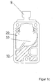
- Fig. 1cFig. 1c
- eine Querschnittsdarstellung durch den Grundkörper der Montagegehäuseanordnung mit einseitig bereits angeordnetem Kontaktblech nebst Montagelasche;a cross-sectional view through the body of the mounting housing assembly with one side already arranged contact plate together with mounting tab;
- Fig. 2Fig. 2
- eine perspektivische Ansicht eines kompletten Montagegehäuses mit Kontaktstücken in Form von Messerklemmkontakten unda perspective view of a complete mounting housing with contacts in the form of blade terminal contacts and
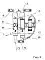
- Fig. 3Fig. 3
- eine Darstellung einer möglichen Verschaltung mit externem Stromsensor und Kontrollelektronik.a representation of a possible interconnection with external current sensor and control electronics.
Die Montagegehäuseanordnung, wie in den
Im Grundkörper 1 ist eine bevorzugt zylindrische Durchgangsbohrung 20 eingebracht, die sich in Längsachsenrichtung des Grundkörpers 1 erstreckt.In the
Die Bohrung 20 ist abgestimmt auf den Außendurchmesser des Einsatzes 2, welcher der vorgefertigten Spannungsdurchschlagsicherung (SDS) entspricht.The
An einer Außenseite des Grundkörpers 1 ist eine Beschriftungsfläche 8 für notwendige Typen- und Parameterangaben vorgesehen.On an outer side of the
Eine Kontakthülse 5, deren Durchmesser wiederum abgestimmt ist auf den Durchmesser des Einsatzes 2, dient einem Längenausgleich und sichert die notwendige Kontaktverbindung zwischen den Stirnseiten des Einsatzes 2 und den zum Grundkörper 1 weisenden Seiten der Kontaktbleche 3, die aus einem metallischen Material bestehen.A
Es sei an dieser Stelle angemerkt, dass der Grundkörper 1 aus einem Isoliermaterial gefertigt ist und z.B. in Kunststoffspritztechnik hergestellt wird.It should be noted at this point that the
Ein elastisches Dichtungs- und Ausgleichselement in Form eines Ringes 4 ist an den beiden gegenüberliegenden Enden des Grundkörpers 1 als Zwischenstück bezogen auf das jeweilige Kontaktblech 3 angeordnet. Mit Hilfe von Schrauben 7 erfolgt dann eine Befestigung der Kontaktbleche 3 mit dem Dichtungs- und Ausgleichsring 4 am Grundkörper 1.An elastic sealing and compensating element in the form of a
An den Kontaktblechen 3 angeformt Ist eine Montagelasche 9 vorhanden, die eine leichte Handhabung der Gehäuseanordnung zum Einsetzen in entsprechende Klemmen, wie in der
Die Ausführungsformen nach den
Radial von der Bohrung 20 beabstandet erstreckt sich im Inneren des Grundkörpers 1 ein Druckausgleichsraum 10, um beim Ansprechen der Funkenstrecke freigesetzte Gase ohne Zerstörung der Gehäuseanordnung aufnehmen zu können.Radially spaced from the
Eine komplett montierte Gehäuseanordnung mit im Inneren befindlicher Spannungsdurchschlagsicherung zeigt
Gemäß der Erfindung wird demnach eine impulsstromfeste Integration des Funkenstreckeneinsatzes 2 In den Isolierenden Grundkörper 1 vorgenommen.According to the invention, therefore, a pulse-current-proof integration of the
Die Auswahl des Materials des Grundkörpers 1 und die konstruktive Ausgestaltung ist so vorgenommen, dass ein sicheres Verhalten bei Überlast gegeben ist. Die Innengeometrie ist so ausgeführt, dass mit dem zusätzlichen Druckausgleichsraum eine definierte Druckkontrolle bei Überlast gegeben ist. Weiterhin fixiert die Bohrung 20 den Funkenstreckeneinsatz mechanisch.The selection of the material of the
Wie bereits dargelegt, kann die Außengeometrie des Grundkörpers 1 vorzugsweise zylindrisch ausgebildet, aber auch n-eckig ausgeführt werden.As already stated, the outer geometry of the
Die Kontaktbleche 3 können ein ballige Geometrie besitzen derart, dass der Anpressdruck zur Beherrschung der Kurzschlusskräfte ausreicht und Störlichtbögen vermieden werden.The
Die Dimensionierung der als Innere Verbindung dienenden Kontakthülse 5 in Querschnitt und Materialauswahl ist so ausgelegt, dass die erforderliche Stoßstromfestigkeit erreicht wird.The dimensioning of the serving as an inner
Das zwischen Kontaktblech 3 und Kunststoffgehäuse bzw. Grundkörper 1 jeweils eingebrachte Element 4 in Form eines Dichtungs- und Ausgleichsrings dient dem Ausgleich der Toleranzen der einzelnen im Grundkörper 1 befindlichen Komponenten und sorgt durch die elastischen Eigenschaften und seine Formgebung für die Einhaltung des IP-Schutzgrads, d.h. es wird ein Eindringen von Feuchtigkeit und Staub wirksam verhindert.The introduced between the
Zugleich weist das Ausgleichselement eine Federwirkung auf, die für die stromfeste Kontaktierung notwendig ist und verhindert, dass durch einen zu hohen Anpressdruck der Funkenstreckeneinsatz möglicherweise mechanisch überlastet wird.At the same time, the compensating element on a spring action, which is necessary for the current-tight contact and prevents that may be overloaded mechanically by a too high contact pressure of the spark gap insert.
Die Kontaktstücke 6 können vorzugsweise als flächige Kontakte, wie z.B. Messerkontakte, aber auch als Steckkontakte in runder Form ausgeführt werden. Die spezielle Ausführung erfolgt in Abhängigkeit vom verwendeten Aufnahmegestell bzw. Unterteil der Gesamtanordnung (siehe
Die steckbaren, in der Gehäuseanordnung befindlichen Spannungsdurchschlagsicherungselemente 11 und 11' werden gemäß
Das Trägergestell 12 wird vorzugsweise in einer zweipoligen Ausführung für die Aufnahme von zwei SDS-Elementen ausgeführt. Dabei ist ein SDS-Flement kontaktiert (11) und ein weiteres SDS-Element befindet sich In Reserveschaltung (11').The
Alternativ zu der Bestückung mit zwei SDS-Elementen kann auch eine Bestückung mit einem einzelnen SDS-Element und einer entsprechend stromtragfähig ausgeführten und für den Einsatz in den entsprechenden Kontaktbuchsen geeigneten Kurzschlussbrücke erfolgen.As an alternative to equipping with two SDS elements, it is also possible to equip it with a single SDS element and a short-circuit bridge designed to be current-carrying and suitable for use in the corresponding contact sockets.
Die Aufnahmen für die SDS-Elemente sind elektrisch parallel verschalten. Diese Parallelverschaltung erfolgt über entsprechende stromtragfähige Verbindungen 13 der beiden SDS-Element-Aufnahmen.The recordings for the SDS elements are electrically connected in parallel. This parallel connection takes place via corresponding current-carrying
Der externe Anschluss des Trägergestells erfolgt über im Trägergestell integrierte Anschlussklemmen 14.The external connection of the support frame via integrated in the support frame connecting terminals 14th
Selbstverständlich sind auch mehrpolige Kombinationen unterschiedlicher Anschlussklemmen zur Aufnahme unterschiedlicher Anschlussleitungen möglich.Of course, multi-pole combinations of different terminals for receiving different connection cables are possible.
Eine zusätzliche Ausführung zur Schnellbefestigung auf Hutschiene und damit die Integration in elektrische Schaltanlagen ist im Sinne der Erfindung liegend.An additional design for quick mounting on DIN rail and thus the integration in electrical switchgear is within the meaning of the invention.
Durch eine optional vorgesehene Überwachungseinrichtung kann eine mögliche Alterung der SDS-Elemente detektiert werden. Eine Alterung lässt sich durch einen entsprechend erhöhten Leckstrom nachweisen, der über dem im Neuzustand ausgewiesenen Maximalwert liegt.By an optionally provided monitoring device, a possible aging of the SDS elements can be detected. Aging can be detected by a correspondingly increased leakage current, which is above the maximum value indicated in the new state.
Hierfür ist zusätzlich die Integration einer Überwachungseinrichtung für die SDS-Elemente nebst Anzeigeeinrichtung Im Trägergestell möglich.For this purpose, the integration of a monitoring device for the SDS elements in addition to display device in the support frame is also possible.
Diese Überwachungseinrichtung besteht aus einem Stromsensor 16 zur Leckstromüberwachung und einer mit dem Sensor 16 elektrisch verbundenen Kontrollelektronik 17.This monitoring device consists of a
Der Stromsensor 16 kann in einen Anschlusspfad des Trägergestells, aber auch in den Grundkörper selbst integriert werden.The
Die Kontrollelektronik ist durch einstellbare Stromschwellen an den jeweiligen Anwendungsfall anpassbar.The control electronics can be adapted to the respective application by means of adjustable current thresholds.
Letztendlich ermöglicht die optionale Überwachungseinrichtung das Detektieren des Ansprechens der SDS-Elemente. Dies ist über eine Messung des Fehlerstroms möglich, der dann einen einstellbaren Grenzwert überschreitet.Finally, the optional monitor allows detection of the response of the SDS elements. This is possible by measuring the fault current, which then exceeds an adjustable limit.
Die Überschreitung des Grenzwerts kann alternativ oder gleichzeitig zur Anzeige vor Ort noch über einen entsprechenden Schaltkontakt in einer entsprechend übergeordneten Kontrolleinrichtung im Sinne einer Fernmeldung eingebunden werden.The exceeding of the limit value can alternatively or simultaneously for on-site display via a corresponding switching contact in a be integrated according to higher-level control device in the sense of a remote message.
Eine mechanische Verriegelung 18 bzw. Entriegelung der Steckplätze für die SDS-Elemente verhindert, dass beide Plätze gleichzeitig offen, d.h. unbestückt sind. Die mechanische Verriegelung und Entriegelung der beiden Steckplätze verhindern auch, dass ein kurzgeschlossenes SDS-Element entnommen wird, bevor ein zweites paralleles SDS-Element eingesetzt wird.A
Durch die vorgestellte Lösung ergeben sich einfachere und flexiblere Anschlussmöglichkeiten durch eine erweiterte Klemmenausführung. Außerdem ist eine schnellere Austauschbarkeit der kurzgeschlossenen Sicherungs-Einsätze und dadurch eine Reduzierung der Arbeitsschritte möglich. Die Gestaltung der Kontaktstücke ermöglicht eine Integration in übliche Schaltanlagen. Durch eine Vor Ort-Anzeigeeinrichtung erhöht sich die Personensicherheit und damit auch die Bedienungsfreundlichkeit. Es ist hierdurch eine schnellere und einfachere Detektierung von fehlerhaften, kurzgeschlossenen Spannungsdurchschlagsicherungen möglich.The presented solution results in simpler and more flexible connection options due to an extended terminal design. In addition, a faster interchangeability of the short-circuited fuse inserts and thereby reducing the work steps is possible. The design of the contacts allows integration into conventional switchgear. An on-site display increases personal safety and thus ease of use. It is thereby possible a faster and easier detection of faulty, short-circuited voltage breakdown.
Durch die einstellbare Stromerkennung auch möglicher Streuströme ist die Anlagenverfügbarkeit erhöht, da eine Alterung der einzelnen Spannungsdurchschlagsicherungen erkannt werden kann und ein rechtzeitiger, vorsorglicher Austausch gealteter Elemente vornehmbar ist.Due to the adjustable current detection also possible stray currents, the system availability is increased because an aging of the individual voltage breakdown fuses can be detected and a timely, precautionary replacement of aged elements vornehmbar.
Die jeweilige Montagegehäuseanordnung mit darin aufgenommenem SDS-Element kann mit Hilfe der am Gehäuse angebrachten Montagelaschen durch das Servicepersonal auch bei einem eventuell noch anliegenden Oberleitungskurzschluss gefahrlos mit einer entsprechenden Sicherheitsausrüstung ausgetauscht werden. Die anstehende Fremdspannung kann dabei maximal die Ansprechspannung der entsprechenden Spannungssicherung erreichen. Eine Einhaltung der entsprechenden Spannungs-Zeitkennlinien ist damit gewährleistet. Noch anliegende Fremdspannungen werden angezeigt mit der Folge einer verbesserten Personensicherheit.The respective mounting housing assembly with SDS element accommodated therein can be safely replaced with the appropriate safety equipment with the help of the mounted on the housing mounting tabs by the service personnel in case of a possibly still present trolley short circuit. The pending external voltage can reach a maximum of the operating voltage of the corresponding voltage fuse. Compliance with the corresponding voltage-time characteristics is guaranteed. Still applied external voltages are displayed with the result of improved personal safety.
- 11
- Grundkörper / KunststoffgehäuseBasic body / plastic housing
- 22
- Einsatz / Spannungsdurchschlagsicherungs-PilleInsert / voltage fuse pill
- 33
- Kontaktblechcontact sheet
- 44
- Dichtungs- und AusgleichsringSealing and compensation ring
- 55
- Kontakthülsecontact sleeve
- 66
- Kontaktstückcontact piece
- 77
- Schraubescrew
- 88th
- Typenschild / BeschriftungsflächeNameplate / labeling area
- 99
- Montagelaschemounting tab
- 1010
- DruckausgleichsraumPressure equalization chamber
- 1111
- Steckplatz für SDS-ElementSlot for SDS element
- 11'11 '
-
Steckplatz 2 für SDS-Element
Slot 2 for SDS element - 1212
- Trägergestellsupport frame
- 1313
- stromtragfähige Verbindungcurrent carrying compound
- 1414
- Anschlussklemmeterminal
- 1515
- KontaktbuchseContact socket
- 1616
- Stromsensorcurrent sensor
- 1717
- Kontrollelektronikcontrol electronics
- 1818
- mechanische Verriegelungmechanical locking
- 2020
- Öffnungopening
Claims (11)
- Assembly housing arrangement for the pulsed current resistant integration of at least one pre-fabricated electrical breakdown fuse, in particular based on a spark gap,
wherein a base body (1) made of a pressure-loadable insulating material is provided, which on at least one side has an opening for receiving an insert (2) in the form of the electrical breakdown fuse, wherein the opening (20) has a contour which fixes the insert (2) with respect to its position and, starting at the opening (20), a pressure compensation chamber (10) extends within the base body (1),
characterized in that
on opposite sides of the base body (1) contact plates (3) are located which are mechanically connected to the base body (1), wherein the opening (20) extends as far as the contact plates (3) and is closed off by the same and further the insert (2) located in the opening (20) comes into electrical contact with the contact plates (3) and the outer sides of the contact plates (3) have contact pieces (6) as external contacts which are oriented in the direction of the longitudinal axis of the whole arrangement. - Arrangement according to claim 1,
characterized in that
extensions in the form of assembling tabs (9) are provided on the base body (1) and/or the contact plates (3). - Arrangement according to claim 2,
characterized in that
the assembling tabs (9) are part of the respective contact plate (3) and are formed integrally with the same. - Arrangement according to one of the preceding claims,
characterized in that
a contacting and pressure sleeve (5) is located in the opening (20) for producing the electrical connection between the insert (2) and the respective contact plate (3). - Arrangement according to one of the preceding claims,
characterized in that
the electrical breakdown fuse insert (2) has a cylindrical shape with contact surfaces on the end faces. - Arrangement according to claim 5,
characterized in that
the opening (20) is formed as a cylindrical bore, which is joined via a radial section by the pressure compensation chamber (10). - Arrangement according to one of the preceding claims,
characterized in that
the contact plates (3) can be interchanged with contact pieces (6) so as to allow an adaptation to different contact terminal shapes. - Arrangement according to one of the preceding claims,
characterized in that
the base body (1) has a label surface (8) with type and parameter information on an outer side section. - Arrangement according to one of the preceding claims,
characterized in that
the opening (20) is formed as a through bore which is closable by the contact plates (3), wherein the contact plates (3) are non-positively and/or positively connected to the base body. - Arrangement according to one of the preceding claims,
characterized in that
a sealing and adjustment ring (4) is disposed between the contact plate(s) (3) and the base body (1). - Arrangement according to one of the preceding claims,
characterized in that
a current sensor (16) for detecting the leakage current in the operating case is provided on or in the housing (1), wherein an estimation of the ageing behavior of the electrical breakdown fuse is accomplished by a detected change of the leakage current.
Applications Claiming Priority (3)
| Application Number | Priority Date | Filing Date | Title |
|---|---|---|---|
| DE202007004921 | 2007-04-03 | ||
| DE102008004243A DE102008004243A1 (en) | 2007-04-03 | 2008-01-14 | Assembly housing arrangement for prefabricated electrical breakdown fuse in electrical switchgear and control gear, has contact plates comprising outer sides with contact pieces oriented in direction of longitudinal axis of arrangement |
| PCT/EP2008/051164 WO2008119575A1 (en) | 2007-04-03 | 2008-01-31 | Assembly housing arrangement for the pulsed current resistant integration of at least one pre-made electrical breakdown fuse |
Publications (2)
| Publication Number | Publication Date |
|---|---|
| EP1999828A1 EP1999828A1 (en) | 2008-12-10 |
| EP1999828B1 true EP1999828B1 (en) | 2009-12-09 |
Family
ID=39308038
Family Applications (1)
| Application Number | Title | Priority Date | Filing Date |
|---|---|---|---|
| EP08708478A Not-in-force EP1999828B1 (en) | 2007-04-03 | 2008-01-31 | Assembly housing arrangement for the pulsed current resistant integration of at least one pre-made electrical breakdown fuse |
Country Status (2)
| Country | Link |
|---|---|
| EP (1) | EP1999828B1 (en) |
| WO (1) | WO2008119575A1 (en) |
Families Citing this family (1)
| Publication number | Priority date | Publication date | Assignee | Title |
|---|---|---|---|---|
| DE102011102864A1 (en) * | 2010-10-22 | 2012-04-26 | Dehn + Söhne GmbH | Spark gap with several series-connected, stacked single spark gaps |
Family Cites Families (3)
| Publication number | Priority date | Publication date | Assignee | Title |
|---|---|---|---|---|
| GB813680A (en) * | 1956-12-24 | 1959-05-21 | Asea Ab | Pressure relief arrangements for lightning arresters |
| JP2000021548A (en) * | 1998-06-30 | 2000-01-21 | Toshiba Lighting & Technology Corp | Lightning arrester and distribution board |
| DE19921772C2 (en) * | 1999-04-08 | 2003-10-02 | Dehn & Soehne | Spark gap insert as voltage breakdown protection to protect single-rail track circuits |
-
2008
- 2008-01-31 WO PCT/EP2008/051164 patent/WO2008119575A1/en active Application Filing
- 2008-01-31 EP EP08708478A patent/EP1999828B1/en not_active Not-in-force
Also Published As
| Publication number | Publication date |
|---|---|
| WO2008119575A1 (en) | 2008-10-09 |
| EP1999828A1 (en) | 2008-12-10 |
Similar Documents
| Publication | Publication Date | Title |
|---|---|---|
| DE102007030653B4 (en) | Snubber | |
| DE2738077A1 (en) | FAIL-PROOF DEVICE WITH MULTIPLE FUNCTIONS FOR OVERVOLTAGE PROTECTION DEVICES | |
| EP2949019B1 (en) | Measuring system for continuous monitoring a high-tension feed-through | |
| DE102007051854B4 (en) | Surge arrester with a housing and with at least one discharge element | |
| EP2561519B1 (en) | Overvolatge protection element | |
| DE102006052955A1 (en) | Surge arrester for use in e.g. photovoltaic system, has link type clamp arranged in movement path of conductor section or link and comprising end coming in contact with link when switch guide is activated | |
| WO2014091019A1 (en) | Overvoltage protection device | |
| EP1999828B1 (en) | Assembly housing arrangement for the pulsed current resistant integration of at least one pre-made electrical breakdown fuse | |
| DE202008016322U1 (en) | Surge arresters | |
| EP0678953B1 (en) | Cable termination for a metal-clad gas-insulated high voltage switch installation | |
| DE102016207292B4 (en) | Electrical protection device and transformer with such | |
| EP3713022B1 (en) | Electrical surge protection element | |
| EP0856925A2 (en) | Voltage transformer | |
| DE102008004243A1 (en) | Assembly housing arrangement for prefabricated electrical breakdown fuse in electrical switchgear and control gear, has contact plates comprising outer sides with contact pieces oriented in direction of longitudinal axis of arrangement | |
| EP1030421A1 (en) | Fitting element for cable core | |
| DE19921772A1 (en) | Spark gap insert for protecting electric single-track circuits from overvoltages, comprises electrode plates with spark gap between and recess with gas discharge diverter | |
| EP0110008A2 (en) | Connection device with a fuse for enclosed medium voltage switchgear | |
| EP3671792B1 (en) | Assembly of a power distribution component and an electrical tap with an overcurrent protection device | |
| EP3707791B1 (en) | Overvoltage protection device consisting of an isolating housing for receiving at least one surge arrester | |
| EP3276647B1 (en) | Grounding unit for a switching system | |
| DE102007024622A1 (en) | Overvoltage protective device for e.g. electronic measuring circuit, in electrical system, has inner electrode held in electrically conductive contact with electrode in position against restoring force of spring element | |
| DE10000243A1 (en) | Support isolator with high voltage capacitor for capacitive voltage tester of medium or high voltage switchgear installation | |
| EP2774230B9 (en) | Apparatus for accommodating voltage-limiting devices, including voltage-limiting devices resistant to lightning current, in an exchangeable manner | |
| EP2089893B1 (en) | Overcurrent protection unit for use in overvoltage protection devices having high rated voltages | |
| DE4110073A1 (en) | Surge protector for HV electrical distribution system |
Legal Events
| Date | Code | Title | Description |
|---|---|---|---|
| PUAI | Public reference made under article 153(3) epc to a published international application that has entered the european phase |
Free format text: ORIGINAL CODE: 0009012 |
|
| 17P | Request for examination filed |
Effective date: 20080613 |
|
| AK | Designated contracting states |
Kind code of ref document: A1 Designated state(s): AT BE BG CH CY CZ DE DK EE ES FI FR GB GR HR HU IE IS IT LI LT LU LV MC MT NL NO PL PT RO SE SI SK TR |
|
| AX | Request for extension of the european patent |
Extension state: AL BA MK RS |
|
| 17Q | First examination report despatched |
Effective date: 20090319 |
|
| GRAP | Despatch of communication of intention to grant a patent |
Free format text: ORIGINAL CODE: EPIDOSNIGR1 |
|
| GRAS | Grant fee paid |
Free format text: ORIGINAL CODE: EPIDOSNIGR3 |
|
| GRAA | (expected) grant |
Free format text: ORIGINAL CODE: 0009210 |
|
| AK | Designated contracting states |
Kind code of ref document: B1 Designated state(s): AT BE BG CH CY CZ DE DK EE ES FI FR GB GR HR HU IE IS IT LI LT LU LV MC MT NL NO PL PT RO SE SI SK TR |
|
| REG | Reference to a national code |
Ref country code: GB Ref legal event code: FG4D Free format text: NOT ENGLISH |
|
| REG | Reference to a national code |
Ref country code: CH Ref legal event code: EP |
|
| REG | Reference to a national code |
Ref country code: IE Ref legal event code: FG4D |
|
| REF | Corresponds to: |
Ref document number: 502008000238 Country of ref document: DE Date of ref document: 20100121 Kind code of ref document: P |
|
| REG | Reference to a national code |
Ref country code: NL Ref legal event code: VDEP Effective date: 20091209 |
|
| PG25 | Lapsed in a contracting state [announced via postgrant information from national office to epo] |
Ref country code: FI Free format text: LAPSE BECAUSE OF FAILURE TO SUBMIT A TRANSLATION OF THE DESCRIPTION OR TO PAY THE FEE WITHIN THE PRESCRIBED TIME-LIMIT Effective date: 20091209 Ref country code: SE Free format text: LAPSE BECAUSE OF FAILURE TO SUBMIT A TRANSLATION OF THE DESCRIPTION OR TO PAY THE FEE WITHIN THE PRESCRIBED TIME-LIMIT Effective date: 20091209 Ref country code: NO Free format text: LAPSE BECAUSE OF FAILURE TO SUBMIT A TRANSLATION OF THE DESCRIPTION OR TO PAY THE FEE WITHIN THE PRESCRIBED TIME-LIMIT Effective date: 20100309 Ref country code: LT Free format text: LAPSE BECAUSE OF FAILURE TO SUBMIT A TRANSLATION OF THE DESCRIPTION OR TO PAY THE FEE WITHIN THE PRESCRIBED TIME-LIMIT Effective date: 20091209 |
|
| LTIE | Lt: invalidation of european patent or patent extension |
Effective date: 20091209 |
|
| PG25 | Lapsed in a contracting state [announced via postgrant information from national office to epo] |
Ref country code: PL Free format text: LAPSE BECAUSE OF FAILURE TO SUBMIT A TRANSLATION OF THE DESCRIPTION OR TO PAY THE FEE WITHIN THE PRESCRIBED TIME-LIMIT Effective date: 20091209 Ref country code: HR Free format text: LAPSE BECAUSE OF FAILURE TO SUBMIT A TRANSLATION OF THE DESCRIPTION OR TO PAY THE FEE WITHIN THE PRESCRIBED TIME-LIMIT Effective date: 20091209 Ref country code: SI Free format text: LAPSE BECAUSE OF FAILURE TO SUBMIT A TRANSLATION OF THE DESCRIPTION OR TO PAY THE FEE WITHIN THE PRESCRIBED TIME-LIMIT Effective date: 20091209 Ref country code: LV Free format text: LAPSE BECAUSE OF FAILURE TO SUBMIT A TRANSLATION OF THE DESCRIPTION OR TO PAY THE FEE WITHIN THE PRESCRIBED TIME-LIMIT Effective date: 20091209 |
|
| REG | Reference to a national code |
Ref country code: IE Ref legal event code: FD4D |
|
| PG25 | Lapsed in a contracting state [announced via postgrant information from national office to epo] |
Ref country code: RO Free format text: LAPSE BECAUSE OF FAILURE TO SUBMIT A TRANSLATION OF THE DESCRIPTION OR TO PAY THE FEE WITHIN THE PRESCRIBED TIME-LIMIT Effective date: 20091209 Ref country code: NL Free format text: LAPSE BECAUSE OF FAILURE TO SUBMIT A TRANSLATION OF THE DESCRIPTION OR TO PAY THE FEE WITHIN THE PRESCRIBED TIME-LIMIT Effective date: 20091209 Ref country code: EE Free format text: LAPSE BECAUSE OF FAILURE TO SUBMIT A TRANSLATION OF THE DESCRIPTION OR TO PAY THE FEE WITHIN THE PRESCRIBED TIME-LIMIT Effective date: 20091209 Ref country code: IS Free format text: LAPSE BECAUSE OF FAILURE TO SUBMIT A TRANSLATION OF THE DESCRIPTION OR TO PAY THE FEE WITHIN THE PRESCRIBED TIME-LIMIT Effective date: 20100409 Ref country code: IE Free format text: LAPSE BECAUSE OF FAILURE TO SUBMIT A TRANSLATION OF THE DESCRIPTION OR TO PAY THE FEE WITHIN THE PRESCRIBED TIME-LIMIT Effective date: 20091209 Ref country code: ES Free format text: LAPSE BECAUSE OF FAILURE TO SUBMIT A TRANSLATION OF THE DESCRIPTION OR TO PAY THE FEE WITHIN THE PRESCRIBED TIME-LIMIT Effective date: 20100320 Ref country code: BG Free format text: LAPSE BECAUSE OF FAILURE TO SUBMIT A TRANSLATION OF THE DESCRIPTION OR TO PAY THE FEE WITHIN THE PRESCRIBED TIME-LIMIT Effective date: 20100309 |
|
| BERE | Be: lapsed |
Owner name: DEHN + SOHNE G.M.B.H. + CO KG Effective date: 20100131 |
|
| PG25 | Lapsed in a contracting state [announced via postgrant information from national office to epo] |
Ref country code: SK Free format text: LAPSE BECAUSE OF FAILURE TO SUBMIT A TRANSLATION OF THE DESCRIPTION OR TO PAY THE FEE WITHIN THE PRESCRIBED TIME-LIMIT Effective date: 20091209 Ref country code: MC Free format text: LAPSE BECAUSE OF NON-PAYMENT OF DUE FEES Effective date: 20100131 Ref country code: CZ Free format text: LAPSE BECAUSE OF FAILURE TO SUBMIT A TRANSLATION OF THE DESCRIPTION OR TO PAY THE FEE WITHIN THE PRESCRIBED TIME-LIMIT Effective date: 20091209 |
|
| PLBE | No opposition filed within time limit |
Free format text: ORIGINAL CODE: 0009261 |
|
| STAA | Information on the status of an ep patent application or granted ep patent |
Free format text: STATUS: NO OPPOSITION FILED WITHIN TIME LIMIT |
|
| PG25 | Lapsed in a contracting state [announced via postgrant information from national office to epo] |
Ref country code: GR Free format text: LAPSE BECAUSE OF FAILURE TO SUBMIT A TRANSLATION OF THE DESCRIPTION OR TO PAY THE FEE WITHIN THE PRESCRIBED TIME-LIMIT Effective date: 20100310 Ref country code: CY Free format text: LAPSE BECAUSE OF FAILURE TO SUBMIT A TRANSLATION OF THE DESCRIPTION OR TO PAY THE FEE WITHIN THE PRESCRIBED TIME-LIMIT Effective date: 20091209 |
|
| 26N | No opposition filed |
Effective date: 20100910 |
|
| PG25 | Lapsed in a contracting state [announced via postgrant information from national office to epo] |
Ref country code: DK Free format text: LAPSE BECAUSE OF FAILURE TO SUBMIT A TRANSLATION OF THE DESCRIPTION OR TO PAY THE FEE WITHIN THE PRESCRIBED TIME-LIMIT Effective date: 20091209 |
|
| PG25 | Lapsed in a contracting state [announced via postgrant information from national office to epo] |
Ref country code: BE Free format text: LAPSE BECAUSE OF NON-PAYMENT OF DUE FEES Effective date: 20100131 |
|
| PG25 | Lapsed in a contracting state [announced via postgrant information from national office to epo] |
Ref country code: MT Free format text: LAPSE BECAUSE OF FAILURE TO SUBMIT A TRANSLATION OF THE DESCRIPTION OR TO PAY THE FEE WITHIN THE PRESCRIBED TIME-LIMIT Effective date: 20091209 |
|
| PGFP | Annual fee paid to national office [announced via postgrant information from national office to epo] |
Ref country code: IT Payment date: 20110131 Year of fee payment: 4 |
|
| REG | Reference to a national code |
Ref country code: CH Ref legal event code: PL |
|
| GBPC | Gb: european patent ceased through non-payment of renewal fee |
Effective date: 20120131 |
|
| PG25 | Lapsed in a contracting state [announced via postgrant information from national office to epo] |
Ref country code: PT Free format text: LAPSE BECAUSE OF FAILURE TO SUBMIT A TRANSLATION OF THE DESCRIPTION OR TO PAY THE FEE WITHIN THE PRESCRIBED TIME-LIMIT Effective date: 20100509 Ref country code: HU Free format text: LAPSE BECAUSE OF FAILURE TO SUBMIT A TRANSLATION OF THE DESCRIPTION OR TO PAY THE FEE WITHIN THE PRESCRIBED TIME-LIMIT Effective date: 20100610 Ref country code: LU Free format text: LAPSE BECAUSE OF NON-PAYMENT OF DUE FEES Effective date: 20100131 |
|
| PG25 | Lapsed in a contracting state [announced via postgrant information from national office to epo] |
Ref country code: CH Free format text: LAPSE BECAUSE OF NON-PAYMENT OF DUE FEES Effective date: 20120131 Ref country code: TR Free format text: LAPSE BECAUSE OF FAILURE TO SUBMIT A TRANSLATION OF THE DESCRIPTION OR TO PAY THE FEE WITHIN THE PRESCRIBED TIME-LIMIT Effective date: 20091209 Ref country code: LI Free format text: LAPSE BECAUSE OF NON-PAYMENT OF DUE FEES Effective date: 20120131 Ref country code: GB Free format text: LAPSE BECAUSE OF NON-PAYMENT OF DUE FEES Effective date: 20120131 |
|
| PG25 | Lapsed in a contracting state [announced via postgrant information from national office to epo] |
Ref country code: IT Free format text: LAPSE BECAUSE OF NON-PAYMENT OF DUE FEES Effective date: 20120131 |
|
| REG | Reference to a national code |
Ref country code: AT Ref legal event code: MM01 Ref document number: 451743 Country of ref document: AT Kind code of ref document: T Effective date: 20130131 |
|
| PG25 | Lapsed in a contracting state [announced via postgrant information from national office to epo] |
Ref country code: AT Free format text: LAPSE BECAUSE OF NON-PAYMENT OF DUE FEES Effective date: 20130131 |
|
| REG | Reference to a national code |
Ref country code: FR Ref legal event code: PLFP Year of fee payment: 8 |
|
| PGFP | Annual fee paid to national office [announced via postgrant information from national office to epo] |
Ref country code: FR Payment date: 20150130 Year of fee payment: 8 |
|
| PGFP | Annual fee paid to national office [announced via postgrant information from national office to epo] |
Ref country code: DE Payment date: 20150327 Year of fee payment: 8 |
|
| REG | Reference to a national code |
Ref country code: DE Ref legal event code: R119 Ref document number: 502008000238 Country of ref document: DE |
|
| REG | Reference to a national code |
Ref country code: FR Ref legal event code: ST Effective date: 20160930 |
|
| PG25 | Lapsed in a contracting state [announced via postgrant information from national office to epo] |
Ref country code: DE Free format text: LAPSE BECAUSE OF NON-PAYMENT OF DUE FEES Effective date: 20160802 |
|
| PG25 | Lapsed in a contracting state [announced via postgrant information from national office to epo] |
Ref country code: FR Free format text: LAPSE BECAUSE OF NON-PAYMENT OF DUE FEES Effective date: 20160201 |