EP1999453B1 - Metal loss rate sensor and measurement using a mechanical oscillator - Google Patents
Metal loss rate sensor and measurement using a mechanical oscillator Download PDFInfo
- Publication number
- EP1999453B1 EP1999453B1 EP07751957.7A EP07751957A EP1999453B1 EP 1999453 B1 EP1999453 B1 EP 1999453B1 EP 07751957 A EP07751957 A EP 07751957A EP 1999453 B1 EP1999453 B1 EP 1999453B1
- Authority
- EP
- European Patent Office
- Prior art keywords
- deposition
- corrosion
- mechanical oscillator
- metal loss
- metal
- Prior art date
- Legal status (The legal status is an assumption and is not a legal conclusion. Google has not performed a legal analysis and makes no representation as to the accuracy of the status listed.)
- Active
Links
Images





Classifications
-
- G—PHYSICS
- G01—MEASURING; TESTING
- G01N—INVESTIGATING OR ANALYSING MATERIALS BY DETERMINING THEIR CHEMICAL OR PHYSICAL PROPERTIES
- G01N17/00—Investigating resistance of materials to the weather, to corrosion, or to light
- G01N17/04—Corrosion probes
-
- G—PHYSICS
- G01—MEASURING; TESTING
- G01N—INVESTIGATING OR ANALYSING MATERIALS BY DETERMINING THEIR CHEMICAL OR PHYSICAL PROPERTIES
- G01N29/00—Investigating or analysing materials by the use of ultrasonic, sonic or infrasonic waves; Visualisation of the interior of objects by transmitting ultrasonic or sonic waves through the object
- G01N29/02—Analysing fluids
- G01N29/022—Fluid sensors based on microsensors, e.g. quartz crystal-microbalance [QCM], surface acoustic wave [SAW] devices, tuning forks, cantilevers, flexural plate wave [FPW] devices
-
- G—PHYSICS
- G01—MEASURING; TESTING
- G01N—INVESTIGATING OR ANALYSING MATERIALS BY DETERMINING THEIR CHEMICAL OR PHYSICAL PROPERTIES
- G01N29/00—Investigating or analysing materials by the use of ultrasonic, sonic or infrasonic waves; Visualisation of the interior of objects by transmitting ultrasonic or sonic waves through the object
- G01N29/22—Details, e.g. general constructional or apparatus details
- G01N29/30—Arrangements for calibrating or comparing, e.g. with standard objects
-
- G—PHYSICS
- G01—MEASURING; TESTING
- G01N—INVESTIGATING OR ANALYSING MATERIALS BY DETERMINING THEIR CHEMICAL OR PHYSICAL PROPERTIES
- G01N2291/00—Indexing codes associated with group G01N29/00
- G01N2291/02—Indexing codes associated with the analysed material
- G01N2291/025—Change of phase or condition
- G01N2291/0256—Adsorption, desorption, surface mass change, e.g. on biosensors
-
- G—PHYSICS
- G01—MEASURING; TESTING
- G01N—INVESTIGATING OR ANALYSING MATERIALS BY DETERMINING THEIR CHEMICAL OR PHYSICAL PROPERTIES
- G01N2291/00—Indexing codes associated with group G01N29/00
- G01N2291/02—Indexing codes associated with the analysed material
- G01N2291/025—Change of phase or condition
- G01N2291/0258—Structural degradation, e.g. fatigue of composites, ageing of oils
-
- G—PHYSICS
- G01—MEASURING; TESTING
- G01N—INVESTIGATING OR ANALYSING MATERIALS BY DETERMINING THEIR CHEMICAL OR PHYSICAL PROPERTIES
- G01N2291/00—Indexing codes associated with group G01N29/00
- G01N2291/02—Indexing codes associated with the analysed material
- G01N2291/028—Material parameters
- G01N2291/02818—Density, viscosity
-
- G—PHYSICS
- G01—MEASURING; TESTING
- G01N—INVESTIGATING OR ANALYSING MATERIALS BY DETERMINING THEIR CHEMICAL OR PHYSICAL PROPERTIES
- G01N2291/00—Indexing codes associated with group G01N29/00
- G01N2291/04—Wave modes and trajectories
- G01N2291/042—Wave modes
- G01N2291/0427—Flexural waves, plate waves, e.g. Lamb waves, tuning fork, cantilever
Definitions
- the present invention relates to a metal loss measurement system for the detection of corrosion and for measuring the rate of metal mass loss.
- the invention may be applied generally to the detection of metal-loss by corrosion and/or erosion species in single or multiphase fluids.
- the present invention relates to the on-stream detection of metal-loss corrosion and/or erosion during an industrial production process.
- the actual service environment may be aqueous, hydrocarbon, chemical or a combination.
- Corrosive species involved in the production and processing of crude oil and hydrocarbons may cause metal-loss corrosion of production, transfer, storage, and processing equipment.
- Erosive species typically involve fluid and/or solids turbulence causing metal loss from mechanical actions rather than chemical.
- these corrosive/erosive species may be hydrocarbon, hydrocarbon containing materials, or aqueous, or combinations thereof.
- streams may be single or multi-phase (solids, liquids, gases).
- High performance, relatively low-cost corrosion (erosion) sensing technology as in the instant invention would enable, for example, optimization utilization of corrosive crudes and corrosion inhibitor additions, and reductions in unplanned capacity loss, turnaround time, and inspection costs due to corrosion-induced equipment failures. Additional value is achievable with the application of the instant invention to corrosion monitoring of transfer, process, and storage equipment used for crude oil, fractions and derived products, and chemicals and other industries concerned with corrosion and erosion. Further value is achievable with the application to monitoring metal-loss corrosion in equipment used for the extraction of crude oil from subsurface and subsea deposits. In these and other services, a by-product of the corrosion is scale or other depositions that are adherent to the containment surface. A feature of the instant invention is that the metal loss measurement is not compromised by these non-metallic depositions.
- One limitation relates to sensitivity versus useful sensor life. Increasing sensitivity of the conventional electrical resistance probe is achieved by decreasing the thickness of the sensing element. However, the decrease in thickness results in a reduced life of the probe. Once corrosion results in a breach of the element, the probe will no longer function and must be replaced. In an operating process unit, on-stream probe replacement poses various safety and hazard issues.
- Another limitation of the electrical resistance probes relates to their inherent signal variability. The signal variability caused by thermal changes and other factors that affect electrical resistance necessitate long data collection periods (often a week or longer) to establish a reliable trend. While conventional electrical resistance probes are based on understood theoretical principles, these probes often provide low reliability and poor sensitivity to corrosion rates due to limitations in their design and manufacture. The typical output is often difficult for estimating a quantitative corrosion rate.
- Patent US 6,928,877 and US application 2006/0037399 both employ resonators and teach a relationship between the resonance frequency and mass change.
- the relationship taught by the prior art is consistent with the well-known solution described above for a single degree of freedom lightly damped mechanical oscillator: a mass decrease will result in a frequency increase and a mass increase will result in a frequency decrease.
- the instant invention teaches away from the prior art by discovering and utilizing that mass decrease from corrosion/erosion can also result in a resonance frequency decrease. Clearly this finding is not obvious in light of the teachings of the prior art. However, this finding is actually consistent with the governing equations previously listed.
- the instant invention has utilized that the stiffness of the resonator device is also governed by the system mass.
- US 6,928,877 also teaches to make the mass additions or losses at the tip of the resonator.
- the instant invention teaches away from making the tip the mass change location.
- the instant invention provides details for minimizing any mass change at the resonator tip.
- the resonator's mass change location is designed to be close to tine the attachment point.
- mass loss has a sufficient impact on system stiffness as to cause a resonance frequency decrease.
- mass change at this location on the tuning fork resonator is controlling the system resonance frequency because of the corresponding change to stiffness.
- mass addition from corrosion scale or fouling near the base has minimal impact on the resonance frequency because scale and fouling do not significantly contribute to system stiffness.
- US application 2006/0037399 also teaches away from employing stiffness changes to the resonator inherent mass by the use of installing corrodible material in pockets. That application describes the use of pockets to facilitate the periodic replacement of corrodible elements installed in the pockets.
- the ability to employ the device stiffness of the instant invention is dependent upon the corrodible element being an integral element of the resonator (e.g. attached securely via welding).
- Corrodible elements attached by means of pockets in US application 2006/0037399 would not meet the criteria enabling a stiffness change to the resonator. Attachment via pockets can only enable a mass change
- GB-2300264 relates to a method for determining metal dissolution rates in fuels.
- CA-1235744 relates to a method and device for measuring corrosivity of liquids.
- GB-2285508 relates to a corrosive gas detector.
- DE-19512220 discloses a mechanical oscillator metal loss sensor for use in a corrosive environment, comprising a tuning fork made from a material which is corrodible in said environment; the resonant frequency increase of said oscillator is used to indicate metal loss due to corrosion and/or erosion.
- US 6,928,877 does not consider the situation of simultaneous metal mass loss and fouling deposition.
- US application 2006/0037399 teaches that mass loss will increase the resonance frequency and that fouling deposition will decrease the resonance Q. Therefore, 2006/0037399 teaches that the fouling condition in the presence of mass loss (corrosion or erosion) can be recognized by the Q measurement.
- the application teaches that a neural network or artificial intelligence can be used to infer corrosion and fouling conditions from the resonance parameters.
- the instant invention teaches away from these empirical and unreliable approaches by designing a probe where the resonance frequency is primarily dependent upon corrosion (steel) mass loss and is substantially insensitive to deposition from fouling or corrosion products.
- the present invention is a corrosion/erosion sensor and a method for its use in a corrosive liquid or gas environment, as defined in claims 1 and 6, respectively.
- the invention uses the changes in the resonance parameters of a mechanical oscillator to determine the metal mass loss of the oscillator.
- several corrosion mechanisms also result in scale deposition. Since the desired result is metal mass loss, the effects of scale deposition should be considered.
- An example of corrosion scale in refining processes is iron sulfide: formed by the iron removal from the pressure containment boundary reacting with various sulfur species in the process fluids.
- some processes are fouling resulting in deposits such as coke, inorganic salts, or wax.
- Ammonium chloride is an example of a salt deposition that occurs in various aqueous containing streams in the processing of crude oils. Coking can occur when the temperature of the metal surface is higher than the temperature of the service fluid.
- the present invention determines metal loss, including loss from, corrosion employing a mechanical design that minimizes the interference from deposition.
- the sensor consists of a mechanical oscillator.
- the oscillator has a vibrating element such as tuning fork tines.
- the cross-sectional shape of the tines may be circular, rectangular, or as otherwise determined by finite element analysis described subsequently.
- These vibrating elements are attached to a diaphragm.
- the vibrating elements have regions that respond to the service fluid at different corrosion rates.
- the vibrating element includes a base and a tip region.
- the oscillator has a resonance frequency, f, and the quality factor associated with the resonance, Q.
- the resonance factor Q is inversely proportional to the total system damping.
- the mechanical excitation may be provided by the flow of the service fluid or by active excitation at the diaphragm.
- this active excitation may be provided by a piezoceramic driver.
- an external energy source such as a piezoceramic driver, it is not required to continuously provide the excitation.
- the excitation can be applied at the times it is desired to interrogate the corrosion sensor.
- a single tuning fork with two regions of differing corrosion resistance is used, where one of the regions does not corrode at all.
- both regions are subjected simultaneously to the corrosive environment.
- a second non-corrodible tuning fork is used as a reference fork.
- both resonance frequency and Q are available in the determination of metal mass loss and scale/fouling deposition.
- the second fork is used to track process fluid changes such as viscosity, density and temperature not attributed to corrosion.
- thermocouple where viscosity and density changes take place as a function of temperature for a fixed composition. Changes caused by depositions are addressed using the Q parameter.
- the existing commercial applications include the on-line in-situ measurement of fluid level, density and / or viscosity of process streams in a wide range of industries.
- the invention involves the measurement of changes in the resonant parameters (frequency, Q) of a tuning fork immersed in a process stream to detect metal loss.
- the current commercially available devices use these parameters to determine the density and the viscosity of the medium.
- the underlying assumption in these devices for measuring fluid level, density and / or viscosity is that the mass of the oscillator is fixed and its mechanical properties are fixed at the operating temperature. Another assumption is that there is no mass deposition on the tuning fork by the service fluid.
- Some commercial systems available include a temperature measurement to compensate for changes in mechanical properties.
- the material used for the oscillator is compatible (e.g. non-corrosive) with the process fluid in the intended application.
- the present invention uses the changes in the tuning fork resonance parameters caused by a corrosion/erosion mass loss.
- a complication arises in that several corrosion mechanisms also result in scale deposition or may be accompanied by fouling deposition. Since the desired result is to measure metal mass loss, the effects of these depositions should be considered.
- Several distinct embodiments have been developed to address these issues.
- a device would be constructed which employs two mechanical oscillators.
- One oscillator would be made of a material totally compatible (non-corrodible) with the process fluid (for example stainless steel or other high alloy material known to be fully compatible with the service), and the other oscillator would include some materials that can corrode.
- this corroding material would be of the same composition as the service pressure boundary (e.g. pipe or pressure vessel).
- This approach of using two oscillators can be used to minimize effects of corrosion scale or fouling deposition as well as changes associated with process density, viscosity, temperature.
- a single mechanical oscillator is used to fabricate the metal loss probe sensor.
- the following characteristics can be used to enhance the corrosion probe performance: a) shape (e.g. rod, especially shape-configured tines); b) two regions (e.g. tip and base) with differing corrosion responses (achieved using a bi-metallic construction or a single metallic construction employing a corrosion resistant coating (either metallic or non-metallic); d) signal processing (Q and f).
- shape e.g. rod, especially shape-configured tines
- two regions e.g. tip and base
- Q and f signal processing
- the fully compatible mechanical oscillator (non-corrodible) is used as a reference measurement, and it would be used to track process fluid changes (such as viscosity, density and temperature) that would influence the observed changes in the oscillator not attributable to corrosion ( Figure 1a ).
- the second oscillator (with a portion of the material being affected by the process fluid, as in the case of corrosion) experiences the same changes, but in addition it would experience the changes due to the corrosion caused by the fluid.
- This difference in behavior is then translated into a metal loss rate for the material at the process conditions, and is used to monitor the corrosion/erosion rate to determine safe operation, effectiveness of corrosion inhibitors, inhibitor dosage control and / or predicting remaining wall in piping and vessels.
- Other embodiments are also possible and described.
- the corrodible oscillator can be configured using elements with different corrosion rates as describe in the single oscillator embodiment.
- This embodiment of using two oscillators can be used to account for the effects of corrosion scale or fouling deposition.
- the approach also has the benefit of directly accounting for minor variations in the service fluid impacting temperature, density, and viscosity.
- the change in resonance parameters (Q and frequency) of both oscillators can be directly attributable to parameters other than mass loss (e.g. deposition, density, etc.). Any divergence between the resonance parameters of the two oscillators is attributable to mass loss in the oscillator fabricated with the corrodible components. If the two oscillator approach is to be deployed, the effects of corrosion scale deposition can be minimized using the oscillator design using multiple corrodible elements described in the preferred embodiments.
- the multiple tuning fork approach may be less desirable than the single oscillator approach of the preferred embodiments.
- One reason is the cost of materials and installation of the second oscillator.
- the other reason is the assumption that both oscillators will be exposed to the same corrosion and process environments.
- the first principle is that the two oscillators are closely positioned so that changes in process conditions (composition, density, fouling, etc.) impact both oscillators in the same manner.
- the second principle is that both oscillators respond to these changes in a predicable manner.
- the third principle is that corrodible oscillator is constructed in accord with guidelines of this invention to minimize the effects of deposition of the corrosion product.
- the two oscillators would have similar resonance characteristics (frequency, Q, amplitude, harmonics). Then a suitable compensation algorithm is determined for oscillators having unmatched parameters. An algorithm is established by measurement using non-identical oscillators with similar resonance characteristics.
- FIG. 1b An example of tuning fork oscillators with similar but not identical resonance frequency response is shown in Figure 1b .
- the oscillators do respond to changes in a predictable but not identical manner. Using two forks, it is not only necessary to monitor the changes as they occur in the corroding fork but it is also necessary to compare those data with changes in the reference fork. If the third principle identified above is applied, then it is sufficient to track frequency changes to measure metal loss. If the third principle is not applied, then changes in frequency and Q should be monitored.
- Metal thickness loss and deposition gains shown in the examples in this invention represent the single-sided loss or gain.
- the actual metal loss or deposition gain was achieved uniformly over the tuning fork tine. However, it is reported herein as the single-sided result to be consistent with the metal loss (or scale deposition) as it would occur on the interior of the pressure containment boundary (typically the interior of a pipe or a vessel).
- FIG 2 illustrates the tines of a commercial tuning fork level sensor (FORK A) used to collect some data that follow.
- the figure identifies a "diaphragm", "tip” and “base” portion of the tuning fork.
- Figure 3 shows a similar plan view of another commercial tuning fork level sensor (FORK B).
- the tine shape of FORKS A and B are different. As described in this invention, the tine shape has an impact on the sensitivity to measure corrosion.
- the vibratory excitation for tuning FORKS A and B is achieved with a piezoceramic driver attached to the diaphragm.
- Figures 4a and 4b show the effect of deposition, achieved by epoxy addition, and metal mass loss at tine tip and base for FORK A. Mass loss at the tine tip causes an increase in resonance frequency and mass loss at the tine base causes a decrease in the resonance frequency. Deposition at either the tine tip or base causes a decrease in resonance frequency. Additional key observations:
- Figure 5 shows similar data for FORK B. Although the impact of deposition is similar to the FORK A case, the sensitivity to metal mass loss is approximately 50% greater than FORK A. Table 1 summarizes all of the sensitivities for both forks as measured in air and water.
- the primary source of deposition will be from the corrosion scale. Although deposition from fouling is possible in several services where these probes may be used, it is typically expected that depositional fouling with high fluid velocity or non-heat transfer conditions will be minimal.
- one oscillator design approach is to fabricate the tine tip from a corrosive-resistant material (e.g. stainless steel for some services) and fabricate the base from the corrodible material of interest (e.g. carbon steel in some services). Since the diaphragm of the tuning fork now forms the pressure boundary, it should be fabricated from a material that will not fail from corrosion. With this fabrication scenario, metal sulfide, oxide or other scale deposition caused by corrosion will be limited to the base section.
- the tip is configured from a material that will not corrode, there will be no corrosion scale deposits there. Therefore, if the deposition is limited to the by-product of corrosion (in this case iron sulfide), the very limited frequency effects from deposition on the base area ( Figures 4a /b, 5 and Table 1) will have virtually no effect on the resonance frequency. Therefore, under this case resonance frequency can be used as the indicator for metal mass loss.
- an alternative approach is to apply a suitable protective coating, metallic or non-metallic, to the tine tips.
- the present invention includes a component to employ shape optimization.
- shape optimization may be helpful to improve discrimination of mass loss versus scale deposition, there are other potential benefits. For example, it may be desirable to maximize the probe sensitivity near end of probe life.
- FEA finite element analysis
- This work has demonstrated the viability of using finite element analysis (FEA) to model the fork resonance frequency.
- FEA correctly models the resonance frequency response to metal mass loss and epoxy deposition.
- the application of FEA to determine the tine shape can be used to assist in optimizing the tine design for specific applications. Details of FEA can be found in references 1 and 2.
- Oscillators for the metal loss application may be sized for macro (plant applications) or micro (oscillator lengths on the order of 125 micrometers) scale applications (laboratory testing including high throughput experiments).
- the corrosion/erosion sensor determines metal loss in a corrosive/erosive environment.
- the measured frequency, f of the sensor is related to the metal loss.
- the environment may also deposit material on the sensor. This deposition will alter the measured frequency from what it would have been with only corrosion or erosion.
- the corrosion sensor of the instant invention is designed to minimize the impact from deposition, there may be situations where it is necessary to account for deposition. In these situations, the change in frequency attributable to deposition can be determined by the measured value of Q. Q can be related to the change in frequency due to deposition over what it would have been with only metal loss from corrosion or erosion.
- the measured frequency, f when corrected for this change in frequency due to deposition, can then be used to determine metal loss due to corrosion or erosion. This procedure is described below.
- tuning forks of similar design and fabrication will have similar but not identical resonance responses. However, the resonance responses will be sufficiently similar enabling parameter trending on one fork to be predictive of that trend on a similar fork. Although relative values of specific parameters (frequency, Q and amplitude) may vary, trending will be similar.
- the steps to prepare an algorithm for the metal loss measurement are outlined below. Fork 1, Fork 2, etc. are physically different forks but they are of similar geometric design and fabrication.
- Example on using the above algorithm demonstrates a boundary condition case: a situation where deposition after calibration with no new metal loss can be distinguished as deposition rather than metal loss.
- FORK B shown in Figure 5 had measurements of resonance frequency (without deposition) as a function of metal mass removal.
- Figure 6b shows the frequency response as a function of wax mass deposition for the final metal mass loss condition of Figure 5 .
- the measured Q is to estimate deposition This frequency is the target in the absence of either deposition and no additional metal loss Not explicitly used in the calculation process 1178 is the starting frequency from column B Applying the above correction underestimates the target frequency of column B by 2 Hz
- the calibration will consist of a series of measured depositions and corresponding Qs. This approach will reduce interpolation error.
- Table 3 the estimate of wax deposition (1.31g) using Q is slightly greater than the actual deposition of 1.19g.
- the error in metal mass loss is comparatively smaller because of the relative insensitivity of the tine shape to deposition versus metal mass loss. This example demonstrates the viability of measuring metal loss in the presence of deposition covering the entire tines.
- the measurements outlined above provides a template to assess the corrosion of another fork (FORK 2) in the actual test fluid. If the test conditions are corrosive without any deposition, then the measure of resonance frequency established in step 2 is sufficient to estimate the corrosion using Fork 2. The corrosion using Fork 2 is predicted by using the "mils/Hz" established during step 2. If the functional relationship between metal mass loss and resonance frequency is non-linear, then this rate changes as a function of metal loss. It has been observed that this functional relationship will be similar for similarly designed forks (as example Fork 1 and Fork 2 in Figure 1b ) but possibly offset by a constant. Although testing has shown some device to device variability regarding the absolute resonance parameters, for a given commercial design the resonance parameters are sufficiently similar to translate or infer properties measured on Fork 1 to subsequent fork oscillators.
- the condition of deposition and metal mass loss is recognized by a decrease in Q accompanied by a decrease in resonance frequency.
- the orientation of the tines with respect to the process flow has an important consequence. In the extreme cases, the orientation can maximize or minimize the flow impact on the tine surface area. As shown in Figure 9 , the metal loss is greatest when the orientation of the tine is such that the maximum amount of surface area is perpendicular to the flow. The metal loss is minimized when the least amount of surface area is perpendicular to the flow. This phenomenon can be used so that the metal loss sensor can be adjusted to simulate various geometric discontinuities typically found in process piping and vessels.
- the quantity of metal loss can be determined independently from fouling and scale deposition.
- the metal loss rate sometimes referred to as the corrosion rate, can be readily calculated from the information already provided. The calculation divides the amount of incremental metal loss by the corresponding time the metal loss sensor has been exposed to the subject process stream. Calculations can be made over the life of the sensor to indicate a "long term” corrosion rate, or they can be made between discrete readings to give "short term” rates during a particular exposure period.
- a preferred approach for computing the corrosion rate is to calculate a statistically regressed slope on the measured resonance frequency as function of time.
- the metal loss sensor There are two primary application of the metal loss sensor.
- One application is to assess the amount of metal remaining at the pressure boundary (e.g. pipe, vessel, etc.). Typically, it is desired to know the thinnest wall thickness at the pressure boundary. This information provides the operator of the process unit with information that it is necessary to take suitable actions to prevent product leaks from the pressure boundary. This end point of the pressure boundary may be referred to as the retirement limit.
- the amount of quantifiable metal loss from the metal loss oscillator can be used as an indicator of the metal loss at the pressure boundary.
- a second application is to use the metal loss rate as a predictor regarding when the pressure boundary will reach its retirement limit and can additionally prompt direct inspections of the pressure boundary.
- the operator can conservatively estimate the maximum metal loss or metal loss rate by selecting a sensor orientation that maximizes the sensor area that is perpendicular to the flow of the process stream.
- An alternative to measuring the maximum metal loss or the maximum metal loss rate is to measure both the minimum and maximum rates.
- This approach will provide the operator with information regarding the expected extremes of metal loss at the service pressure boundary as a function of geometry. As an example, the operator can have information regarding metal loss in low turbulence straight pipe sections or at pipe elbows where turbulence would be expected to be higher. Typically corrosion and erosion are higher at pipe locations with increased turbulence.
- This application can be achieved by using two metal loss sensors with different geometries. The shape geometries would be selected to optimize hydrodynamics to provide a suitable range of anticipated metal loss rates within the subject service. This approach has an advantage over traditional corrosion probes that requires selection of the correct physical placement in the subject service to achieve a suitable range of metal loss hydrodynamics.
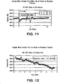
- FIG 11 shows an example where the corrosive fluid is injected into an autoclave operating at 288°C (550°F).
- the ambient temperature fluid causes a short term impact on the resonance frequency, there is no long-term corresponding impact on the resonance frequency.
- the resonator is a tuning fork device with non-corrodible tine tips and a corrodible tine base. Although a frequency decrease would have been anticipated, none was observed.
- the tuning fork was removed from the autoclave, it was observed that a carbonaceous deposit had formed covering the corrodible tine base area. After removing the carbonaceous deposition, pre- and post exposure mass measurements confirmed that there was no steel mass loss during the corrosive exposure.
- FIG. 12 shows the result using the same tuning fork in the same autoclave but where the temperature has been reduced to 232°C (450°F) and a different corrosive fluid. Under these reduced temperature conditions, the propensity for coking is reduced. Figure 12 demonstrates the frequency decrease associated with the measured mass decrease from the tuning fork tines.
- the invention has many refinements and features which may be used to define the scope of the claims.
- the invention provides a mechanical oscillator metal loss sensor for use in a corrosive or erosive environment comprising a mechanical oscillator with two regions that corrode differently, where the regions determine the resonance parameters, and wherein said mechanical oscillator has a resonant frequency, f, and a quality factor, Q.
- the regions may be positioned to determine the resonance parameters.
- the regions may be shaped to determine the resonance parameters.
- the mechanical oscillator is in the shape of a tuning fork.
- the corrosive environment is a gas or a liquid or solid.
- the aforesaid tuning fork has two tines.
- the tuning fork has a tip region not affected by corrosion or erosion metal loss in said environment and a base region that is affected by said environment.
- the metal loss may result in a frequency decrease.
- the metal loss may result also in changes the system stiffness to change in a way that causes a net resonance frequency decrease.
- the mechanical oscillator may be driven by mechanical excitation of the environment.
- the mechanical excitation is due to fluid flow in said environment.
- the mechanical excitation may be by external piezoceramic, electromagnetic or magnetostrictive means.
- the mechanical oscillator metal loss sensor may further comprise a second mechanical oscillator that is not affected by the corrosivity of the environment.
- the environment produces deposition on said oscillator.
- the shape of the mechanical oscillator may maximize metal loss response and minimize deposition response to the resonance parameters.
- the position of the two regions of the mechanical oscillator metal loss sensor for use in a corrosive or erosive environment may minimize deposition response to the resonance parameters.
- the mechanical oscillator may have a tip that is spherical and a tine base that is a rod.
- the base may have mass loss due to corrosion.
- the tip is corrosion resistant..
- the tip may be corrosion resistant and electro-polished.
- the tip may have a deposition gain.
- the corrosion to deposition ratio may be has greater than 50 or greater than 100.
- the fork may be bimetallic.
- the bimetallic fork has a corrosion resistant tip and corrodible base.
- the corrosion resistant tip may be achieved by application of a coating.
- the mechanical oscillator metal loss sensor may be used to determine the corrosion or erosion rate for fluid flow in a corrosive or erosive environment by a metal loss measurement.
- the corrosion rate may be determined by making successive measurements over time to enable the computation of a statistical regression of the mechanical oscillator resonance parameters over the time period.
- corrosive or erosive environment includes a deposition environment.
- the method may include a correction for deposition.
- the corrosive or erosive rate is determined by measuring Q, measuring f, determining the change in f due to Q, correcting f for the change in f, and determining mass loss from the corrected f.
- the mechanical oscillator metal loss sensor may be oriented so that maximum metal loss at high turbulence flow can be determined.
- the mechanical oscillator metal loss sensor may not be located at the high turbulence fluid flow.
- the method may be optimized for a specific application by employing finite element analysis.
- the method may incorporate a concurrent method for measuring temperature to account for changes in temperature, density, and viscosity.
- the oscillator may only be excited when it is desired to interrogate the sensor.
- the second mechanical oscillator may be non-corrodible.
Landscapes
- Life Sciences & Earth Sciences (AREA)
- Physics & Mathematics (AREA)
- General Physics & Mathematics (AREA)
- Pathology (AREA)
- Chemical & Material Sciences (AREA)
- Analytical Chemistry (AREA)
- Biochemistry (AREA)
- General Health & Medical Sciences (AREA)
- Health & Medical Sciences (AREA)
- Immunology (AREA)
- Biodiversity & Conservation Biology (AREA)
- Acoustics & Sound (AREA)
- Ecology (AREA)
- Environmental & Geological Engineering (AREA)
- Environmental Sciences (AREA)
- Testing Resistance To Weather, Investigating Materials By Mechanical Methods (AREA)
- Measuring Temperature Or Quantity Of Heat (AREA)
- Piezo-Electric Or Mechanical Vibrators, Or Delay Or Filter Circuits (AREA)
- Measurement Of Resistance Or Impedance (AREA)
Description
- The present invention relates to a metal loss measurement system for the detection of corrosion and for measuring the rate of metal mass loss. The invention may be applied generally to the detection of metal-loss by corrosion and/or erosion species in single or multiphase fluids. In particular, the present invention relates to the on-stream detection of metal-loss corrosion and/or erosion during an industrial production process. The actual service environment may be aqueous, hydrocarbon, chemical or a combination.
- Corrosive species involved in the production and processing of crude oil and hydrocarbons may cause metal-loss corrosion of production, transfer, storage, and processing equipment. Erosive species typically involve fluid and/or solids turbulence causing metal loss from mechanical actions rather than chemical. For example, these corrosive/erosive species may be hydrocarbon, hydrocarbon containing materials, or aqueous, or combinations thereof. Moreover, streams may be single or multi-phase (solids, liquids, gases).
- High performance, relatively low-cost corrosion (erosion) sensing technology as in the instant invention would enable, for example, optimization utilization of corrosive crudes and corrosion inhibitor additions, and reductions in unplanned capacity loss, turnaround time, and inspection costs due to corrosion-induced equipment failures. Additional value is achievable with the application of the instant invention to corrosion monitoring of transfer, process, and storage equipment used for crude oil, fractions and derived products, and chemicals and other industries concerned with corrosion and erosion. Further value is achievable with the application to monitoring metal-loss corrosion in equipment used for the extraction of crude oil from subsurface and subsea deposits. In these and other services, a by-product of the corrosion is scale or other depositions that are adherent to the containment surface. A feature of the instant invention is that the metal loss measurement is not compromised by these non-metallic depositions.
- Current corrosion sensing technologies, for example electrical resistance probes, fall far short of the performance level required to achieve the economic incentives described above. Their shortcomings are that: One limitation relates to sensitivity versus useful sensor life. Increasing sensitivity of the conventional electrical resistance probe is achieved by decreasing the thickness of the sensing element. However, the decrease in thickness results in a reduced life of the probe. Once corrosion results in a breach of the element, the probe will no longer function and must be replaced. In an operating process unit, on-stream probe replacement poses various safety and hazard issues. Another limitation of the electrical resistance probes relates to their inherent signal variability. The signal variability caused by thermal changes and other factors that affect electrical resistance necessitate long data collection periods (often a week or longer) to establish a reliable trend. While conventional electrical resistance probes are based on understood theoretical principles, these probes often provide low reliability and poor sensitivity to corrosion rates due to limitations in their design and manufacture. The typical output is often difficult for estimating a quantitative corrosion rate.
- It is well established in the literature (
references 3 and 4) that the lightly damped harmonic oscillator with single degree of freedom can be mathematically expressed by a second order differential equation. If the forcing function is sinusoidal, the resonance frequency and quality factor, Q, can be represented by:

- m = system mass
- k = system stiffness
- c = velocity dependent damping
- fo = resonance frequency
- Q = Quality factor (a measure of the system damping and energy dissipation)
- Patent
US 6,928,877 andUS application 2006/0037399 both employ resonators and teach a relationship between the resonance frequency and mass change. The relationship taught by the prior art is consistent with the well-known solution described above for a single degree of freedom lightly damped mechanical oscillator: a mass decrease will result in a frequency increase and a mass increase will result in a frequency decrease. The instant invention teaches away from the prior art by discovering and utilizing that mass decrease from corrosion/erosion can also result in a resonance frequency decrease. Clearly this finding is not obvious in light of the teachings of the prior art. However, this finding is actually consistent with the governing equations previously listed. The instant invention has utilized that the stiffness of the resonator device is also governed by the system mass. Moreover, that relationship between system mass and stiffness is location dependent: the amount of change to the system stiffness is dependent upon where the mass is lost (or gained). The instant invention teaches that by selecting the proper location on the vibrating element, it is possible that the change in the stiffness to mass ratio of equation (1) can be stiffness dominated even though mass is being lost. For that case, a loss of mass will result in a frequency decrease, teaching away from the prior art. -
US 6,928,877 also teaches to make the mass additions or losses at the tip of the resonator. The instant invention teaches away from making the tip the mass change location. In fact, the instant invention provides details for minimizing any mass change at the resonator tip. For the instant invention, the resonator's mass change location is designed to be close to tine the attachment point. At this location, mass loss has a sufficient impact on system stiffness as to cause a resonance frequency decrease. Essentially, mass change at this location on the tuning fork resonator is controlling the system resonance frequency because of the corresponding change to stiffness. Moreover, mass addition from corrosion scale or fouling near the base has minimal impact on the resonance frequency because scale and fouling do not significantly contribute to system stiffness. This observation is understood because the Young's modulus (a measure of a material's stiffness) of scale or fouling is several orders of magnitude lower than steel. However, if scale or fouling deposition were to occur near the resonator tip, the added mass would result in a frequency decrease. Any change to the system stiffness is overshadowed by the mass change. -
US application 2006/0037399 also teaches away from employing stiffness changes to the resonator inherent mass by the use of installing corrodible material in pockets. That application describes the use of pockets to facilitate the periodic replacement of corrodible elements installed in the pockets. The ability to employ the device stiffness of the instant invention is dependent upon the corrodible element being an integral element of the resonator (e.g. attached securely via welding). Corrodible elements attached by means of pockets inUS application 2006/0037399 would not meet the criteria enabling a stiffness change to the resonator. Attachment via pockets can only enable a mass changeGB-2300264 CA-1235744 relates to a method and device for measuring corrosivity of liquids.GB-2285508 -
DE-19512220 discloses a mechanical oscillator metal loss sensor for use in a corrosive environment, comprising a tuning fork made from a material which is corrodible in said environment; the resonant frequency increase of said oscillator is used to indicate metal loss due to corrosion and/or erosion. -
US 6,928,877 does not consider the situation of simultaneous metal mass loss and fouling deposition.US application 2006/0037399 teaches that mass loss will increase the resonance frequency and that fouling deposition will decrease the resonance Q. Therefore,2006/0037399 teaches that the fouling condition in the presence of mass loss (corrosion or erosion) can be recognized by the Q measurement. The application teaches that a neural network or artificial intelligence can be used to infer corrosion and fouling conditions from the resonance parameters. The instant invention teaches away from these empirical and unreliable approaches by designing a probe where the resonance frequency is primarily dependent upon corrosion (steel) mass loss and is substantially insensitive to deposition from fouling or corrosion products. - The focus of
US 6,928,877 and2006/0037399 is to provide a quantitative estimate of mass loss or deposition. Essentially, both provide an alarming function. The instant invention has sufficient precision, stability, and longevity as to provide a mass loss rate quantity. - The present invention is a corrosion/erosion sensor and a method for its use in a corrosive liquid or gas environment, as defined in
claims - The sensor consists of a mechanical oscillator. In the most general embodiment, the oscillator has a vibrating element such as tuning fork tines. As examples, the cross-sectional shape of the tines may be circular, rectangular, or as otherwise determined by finite element analysis described subsequently. These vibrating elements are attached to a diaphragm. The vibrating elements have regions that respond to the service fluid at different corrosion rates. The vibrating element includes a base and a tip region. The oscillator has a resonance frequency, f, and the quality factor associated with the resonance, Q. The resonance factor Q is inversely proportional to the total system damping. The mechanical excitation may be provided by the flow of the service fluid or by active excitation at the diaphragm. As an example, this active excitation may be provided by a piezoceramic driver. When driven by an external energy source, such as a piezoceramic driver, it is not required to continuously provide the excitation. The excitation can be applied at the times it is desired to interrogate the corrosion sensor.
- In one embodiment, a single tuning fork with two regions of differing corrosion resistance is used, where one of the regions does not corrode at all. In a preferred embodiment, both regions are subjected simultaneously to the corrosive environment. In another embodiment, a second non-corrodible tuning fork is used as a reference fork. In both embodiments, both resonance frequency and Q are available in the determination of metal mass loss and scale/fouling deposition. In the dual sensor embodiment, the second fork is used to track process fluid changes such as viscosity, density and temperature not attributed to corrosion. In the special case that uses a reference oscillator and where the corrodible oscillator is constructed to minimize the frequency change caused by corrosion scale deposition, it is sufficient to use resonance frequency to determine metal loss, In the single fork embodiment, the temperature-related changes are accounted for using a thermocouple, where viscosity and density changes take place as a function of temperature for a fixed composition. Changes caused by depositions are addressed using the Q parameter.
-
-
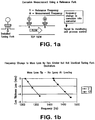
Figure 1a shows a schematic drawing of a dual tuning fork embodiment of the present invention. -
Figure 1b shows the frequency change to mass loss by two similar but not identical tuning forks. -
Figure 2 illustrates the plan view of a commercial tuning fork used to collect data (referred to as fork A). -
Figure 3 illustrates the plan view of a commercial tuning fork used to collect data (referred to as fork B). -
Figure 4a distinguishes the effect of deposition and mass loss at the tine base from that at the tine tip for fork A.Figure 4b makes a direct sensitivity comparison to metal loss and deposition at the base of Fork A. -
Figure 5 shows the effect of deposition over the entire fork tine and mass loss at the tine base for fork B. -
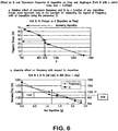
Figure 6a shows the effect on Q and relative change in frequency, f, of deposition on tines and diaphragm for fork, B with metal mass loss equal to 0.25g.Figure 6b shows the absolute effect of resonance frequency and Q with respect to deposition. -
Figure 7 shows the change in Q from mass loss at the tine base for forks A and B. -
Figure 8 shows a comparison between the experiment results and finite element analysis. -
Figure 9 shows the corrosion rate as a function of impact angle. -
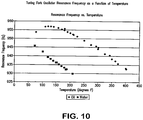
Figure 10 shows the effect of temperature on resonance frequency and Q of another tuning fork, Fork C. -
Figure 11 shows a case where the probe resonance frequency remained constant in a corroding environment with concurrent carbonaceous deposition. -
Figure 12 show the same device ofFigure 11 but in an environment where corrosive fluid has an impact on resonance frequency. -
Figure 13 shows how finite element analysis (FEA) can be used to optimize the paddle shape by minimizing the effect of deposition material. - This invention represents a new application of existing commercial technology. The existing commercial applications include the on-line in-situ measurement of fluid level, density and / or viscosity of process streams in a wide range of industries. The invention involves the measurement of changes in the resonant parameters (frequency, Q) of a tuning fork immersed in a process stream to detect metal loss. The current commercially available devices use these parameters to determine the density and the viscosity of the medium. The underlying assumption in these devices for measuring fluid level, density and / or viscosity is that the mass of the oscillator is fixed and its mechanical properties are fixed at the operating temperature. Another assumption is that there is no mass deposition on the tuning fork by the service fluid. Some commercial systems available include a temperature measurement to compensate for changes in mechanical properties. Moreover, in these commercial systems, the material used for the oscillator is compatible (e.g. non-corrosive) with the process fluid in the intended application.
- The present invention uses the changes in the tuning fork resonance parameters caused by a corrosion/erosion mass loss. However, a complication arises in that several corrosion mechanisms also result in scale deposition or may be accompanied by fouling deposition. Since the desired result is to measure metal mass loss, the effects of these depositions should be considered. Several distinct embodiments have been developed to address these issues.
- In one embodiment, a device would be constructed which employs two mechanical oscillators. One oscillator would be made of a material totally compatible (non-corrodible) with the process fluid (for example stainless steel or other high alloy material known to be fully compatible with the service), and the other oscillator would include some materials that can corrode. Preferably, this corroding material would be of the same composition as the service pressure boundary (e.g. pipe or pressure vessel). This approach of using two oscillators can be used to minimize effects of corrosion scale or fouling deposition as well as changes associated with process density, viscosity, temperature.
- In another embodiment, a single mechanical oscillator is used to fabricate the metal loss probe sensor. Using a single oscillator, the following characteristics can be used to enhance the corrosion probe performance: a) shape (e.g. rod, especially shape-configured tines); b) two regions (e.g. tip and base) with differing corrosion responses (achieved using a bi-metallic construction or a single metallic construction employing a corrosion resistant coating (either metallic or non-metallic); d) signal processing (Q and f). Collectively, this configuration and these parameters are sufficient to measure corrosion accounting for both forms of deposition: corrosion scale and fouling. The concurrent measurement of temperature can be used to account for small changes in the temperature, density, viscosity of the service fluid that may have a corresponding affect on the resonance parameters (Q and f).
- The fully compatible mechanical oscillator (non-corrodible) is used as a reference measurement, and it would be used to track process fluid changes (such as viscosity, density and temperature) that would influence the observed changes in the oscillator not attributable to corrosion (
Figure 1a ). The second oscillator (with a portion of the material being affected by the process fluid, as in the case of corrosion) experiences the same changes, but in addition it would experience the changes due to the corrosion caused by the fluid. This difference in behavior is then translated into a metal loss rate for the material at the process conditions, and is used to monitor the corrosion/erosion rate to determine safe operation, effectiveness of corrosion inhibitors, inhibitor dosage control and / or predicting remaining wall in piping and vessels. Other embodiments are also possible and described. To minimize the impact of corrosion scale deposition, the corrodible oscillator can be configured using elements with different corrosion rates as describe in the single oscillator embodiment. - This embodiment of using two oscillators can be used to account for the effects of corrosion scale or fouling deposition. The approach also has the benefit of directly accounting for minor variations in the service fluid impacting temperature, density, and viscosity. In the absence of any corrosion, the change in resonance parameters (Q and frequency) of both oscillators can be directly attributable to parameters other than mass loss (e.g. deposition, density, etc.). Any divergence between the resonance parameters of the two oscillators is attributable to mass loss in the oscillator fabricated with the corrodible components. If the two oscillator approach is to be deployed, the effects of corrosion scale deposition can be minimized using the oscillator design using multiple corrodible elements described in the preferred embodiments. There are two reasons the multiple tuning fork approach may be less desirable than the single oscillator approach of the preferred embodiments. One reason is the cost of materials and installation of the second oscillator. The other reason is the assumption that both oscillators will be exposed to the same corrosion and process environments.
- There are fundamental principles associated with the two oscillator system. The first principle is that the two oscillators are closely positioned so that changes in process conditions (composition, density, fouling, etc.) impact both oscillators in the same manner. The second principle is that both oscillators respond to these changes in a predicable manner. The third principle is that corrodible oscillator is constructed in accord with guidelines of this invention to minimize the effects of deposition of the corrosion product. In general, the two oscillators would have similar resonance characteristics (frequency, Q, amplitude, harmonics). Then a suitable compensation algorithm is determined for oscillators having unmatched parameters. An algorithm is established by measurement using non-identical oscillators with similar resonance characteristics. An example of tuning fork oscillators with similar but not identical resonance frequency response is shown in
Figure 1b . In this example, the oscillators do respond to changes in a predictable but not identical manner. Using two forks, it is not only necessary to monitor the changes as they occur in the corroding fork but it is also necessary to compare those data with changes in the reference fork. If the third principle identified above is applied, then it is sufficient to track frequency changes to measure metal loss. If the third principle is not applied, then changes in frequency and Q should be monitored. - Metal thickness loss and deposition gains shown in the examples in this invention represent the single-sided loss or gain. The actual metal loss or deposition gain was achieved uniformly over the tuning fork tine. However, it is reported herein as the single-sided result to be consistent with the metal loss (or scale deposition) as it would occur on the interior of the pressure containment boundary (typically the interior of a pipe or a vessel).
- It has been discovered that the resonance effects of mass loss and scale deposition are a function of position on the tuning fork tine.
Figure 2 illustrates the tines of a commercial tuning fork level sensor (FORK A) used to collect some data that follow. The figure identifies a "diaphragm", "tip" and "base" portion of the tuning fork.Figure 3 shows a similar plan view of another commercial tuning fork level sensor (FORK B). The tine shape of FORKS A and B are different. As described in this invention, the tine shape has an impact on the sensitivity to measure corrosion. The vibratory excitation for tuning FORKS A and B is achieved with a piezoceramic driver attached to the diaphragm. -
Figures 4a and 4b show the effect of deposition, achieved by epoxy addition, and metal mass loss at tine tip and base for FORK A. Mass loss at the tine tip causes an increase in resonance frequency and mass loss at the tine base causes a decrease in the resonance frequency. Deposition at either the tine tip or base causes a decrease in resonance frequency. Additional key observations: - 1. At the base, the effect on the resonance change is much more pronounced for metal mass loss than for deposition (difference by approximately a factor of 100). For direct comparison, these parameters are plotted on the same axis in
Figure 4b . - 2. At the tine tip, the relative impacts of steel mass loss and deposition differ by only a factor of 5.
- 3. The data in
Figure 4a of the epoxy deposition at the fork tip were actually collected on four forks of similar construction. Although the four forks used to collect these data are the same model from a single manufacturer, one has a base case resonance frequency approximately 100 Hz lower than the other 3 forks. Notwithstanding this difference, the effect of epoxy deposition on the relative changes in the resonance frequency is predictable and consistent. -
Figure 5 shows similar data for FORK B. Although the impact of deposition is similar to the FORK A case, the sensitivity to metal mass loss is approximately 50% greater than FORK A. Table 1 summarizes all of the sensitivities for both forks as measured in air and water. - For some applications, the primary source of deposition will be from the corrosion scale. Although deposition from fouling is possible in several services where these probes may be used, it is typically expected that depositional fouling with high fluid velocity or non-heat transfer conditions will be minimal. For these non-fouling services, one oscillator design approach is to fabricate the tine tip from a corrosive-resistant material (e.g. stainless steel for some services) and fabricate the base from the corrodible material of interest (e.g. carbon steel in some services). Since the diaphragm of the tuning fork now forms the pressure boundary, it should be fabricated from a material that will not fail from corrosion. With this fabrication scenario, metal sulfide, oxide or other scale deposition caused by corrosion will be limited to the base section. Since the tip is configured from a material that will not corrode, there will be no corrosion scale deposits there. Therefore, if the deposition is limited to the by-product of corrosion (in this case iron sulfide), the very limited frequency effects from deposition on the base area (
Figures 4a /b, 5 and Table 1) will have virtually no effect on the resonance frequency. Therefore, under this case resonance frequency can be used as the indicator for metal mass loss. Rather than using tines of a bi-metallic construction, an alternative approach is to apply a suitable protective coating, metallic or non-metallic, to the tine tips. - However, in other services, there may be deposition from sources other than the corrosion product. Some services are subject to deposition from fouling (coking, wax, and/or inorganic salts). In the event of services subject to deposition from fouling, use of the bi-metallic fork will not be sufficient to prevent deposition on the non-corrodible element (e.g. fork tip). Therefore, deposition can be expected in some services and will have some impact on the resonance frequency. It is well-known in the prior art that deposition on these non-corrodible elements (often various alloys like stainless steel) can be significantly reduced by electro-polishing methods. In cases where fouling deposition is still problematic, the presence of deposition can be detected by trending Q as shown in
Figure 6a/b . As shown inFigure 6b , deposition decreases both Q and the resonance frequency.Figure 6a shows how to estimate the relative frequency decrease corresponding to a measured Q.Figure 7 also shows that metal mass loss at the base does not decrease Q. These findings form the basis of an algorithm (subsequently described) to estimate metal mass loss in the presence of scale deposition on all fork components. - The data in Table 1 and
Figures 4 /5 demonstrate that the shape of the tines can be used to improve the differentiation of metal mass loss and deposition. Using a ball shape at the tine tip has an additional benefit because a spherical shape minimizes surface area to volume ratio. Minimizing the tip surface area has the desirable effect of minimizing the area for deposition. As shown inFigure 13 , minimizing surface area with the spherical shape results in a reduced frequency decrease per thickness of deposition.TABLE 1 Summary of Resonance Frequency Response: Fork A and Fork B Loading Parameter Air Loading Water Loading Fork A Fork B Fork A Fork B Base metal loss (Hz/mil) 12 20 9 16 Base deposition (Hz/mil) ∼ 0.1 < 0.1 ∼ 0.1 < 0.1 Ratio: metal loss to base deposition ∼ 120 ∼ 200 ∼ 90 ∼ 160 Tip deposition gain (Hz/mil) 2 (epoxy) 1.8 (wax) 3 (epoxy) 2 (wax) - The present invention includes a component to employ shape optimization. Although shape optimization may be helpful to improve discrimination of mass loss versus scale deposition, there are other potential benefits. For example, it may be desirable to maximize the probe sensitivity near end of probe life. As shown in
Figure 8 , this work has demonstrated the viability of using finite element analysis (FEA) to model the fork resonance frequency. FEA correctly models the resonance frequency response to metal mass loss and epoxy deposition. The application of FEA to determine the tine shape can be used to assist in optimizing the tine design for specific applications. Details of FEA can be found inreferences - As discussed above, the corrosion/erosion sensor determines metal loss in a corrosive/erosive environment. The measured frequency, f, of the sensor is related to the metal loss. However, the environment may also deposit material on the sensor. This deposition will alter the measured frequency from what it would have been with only corrosion or erosion. Although the corrosion sensor of the instant invention is designed to minimize the impact from deposition, there may be situations where it is necessary to account for deposition. In these situations, the change in frequency attributable to deposition can be determined by the measured value of Q. Q can be related to the change in frequency due to deposition over what it would have been with only metal loss from corrosion or erosion. The measured frequency, f, when corrected for this change in frequency due to deposition, can then be used to determine metal loss due to corrosion or erosion. This procedure is described below.
- As previously described, tuning forks of similar design and fabrication will have similar but not identical resonance responses. However, the resonance responses will be sufficiently similar enabling parameter trending on one fork to be predictive of that trend on a similar fork. Although relative values of specific parameters (frequency, Q and amplitude) may vary, trending will be similar. The steps to prepare an algorithm for the metal loss measurement are outlined below.
Fork 1,Fork 2, etc. are physically different forks but they are of similar geometric design and fabrication. - The most general case allows for the possibility of both metal mass loss and deposition. However, it is noted that in cases of heavy organic deposition corrosion losses are typically small. In contrast, aqueous applications may have thick depositions that may be a precursor as well as a direct cause of the corrosion. A deposition of amine chlorides is an example that absorbs water and becomes locally corrosive. For hydrocarbon (organic) applications, the primary deposition is the corrosion scale and its impact on the resonance frequency measurement is minimized by the bi-metallic fabrication of the tines. Field experience suggests that corrosion product deposition (for example iron sulfide scale) will form rapidly from the outset and then grow very slowly if at all. Although the mechanical oscillator can differentiate between metal loss and deposition, the user should assess the implications for the particular application being served.
- 1. Construct a tuning fork preferably with tines of bi-metallic metallurgy. The metallurgy should be chosen to minimize corrosion at the tine tip area and to be representative of the subject metallurgy at the base area. The metallurgy fork diaphragm should be selected to minimize corrosion. Example materials for the case of refinery streams subject to sulfur corrosion would be stainless steel (non-corrodible) and 5Cr 0.5Mo, respectively for the tine tip and base. This example assumes that the metallurgy of the subject piping is a 5Cr 0.5Mo alloy.
- 2. Fork 1: Using a format outlined in
Figures 4 or5 , measure the fundamental resonance frequency and Q as a function of deposition on the tine near the base. The deposition material should have mechanical stiffness properties and density similar to that of the expected depositions. These measurements should be made in a medium of representative viscosity of the actual test fluid. - 3. Fork 1: Using a format outlined in
Figure 6 , measure the fundamental resonance frequency and Q as a function of deposition over the entire tine and diaphragm. These measurements should be made in a medium of representative density, temperature, and viscosity of the actual test fluid. - 4. Fork 1: Using a format outlined in
Figures 4 or5 , measure the fundamental resonance frequency and Q as a function of metal mass loss at the base of the tines with all depositions removed. - 5. These measurements outlined in steps 2-4 should continue on
Fork 1 in discrete mass loss increments (at the base of the tine) to fork failure. For each increment of metal loss, the application of deposition (step 3) is repeated. By running this calibration procedure to failure of the fork, it provides information to enable replacement prior to failure when installed in the service fluid. By monitoring the resonance frequency and Q, the operator will know when the tuning fork has reached a predefined replacement thickness. - 6. Test cases, shown in
Figure 7 , have demonstrated no decrease in Q for tine shapes shown inFigures 2 and 3 of metal mass loss (without scale deposition). For these fork designs, the system Q (fork + deposition) is controlled by the deposition rather than any modest increase in the fork Q associated with metal mass loss.
The following functions are defined:


- 7.
Figure 10 provides an example relating an effect of fluid temperature on the resonance parameters: frequency and Q. The change in resonance parameters is caused by the combined impact of temperature and the corresponding impact on density and viscosity. For the intended refining and petrochemical applications, temperature variations are likely limited to a range of ± 5.5°C (10°F). Because the high temperature already provides a low viscosity environment, it is unlikely that the service fluid viscosity change caused by small temperature variations will have a significant impact. However, compensation for temperature is readily incorporated into the measurement process. By making a concurrent temperature measurement, a tabulation of adjustment factors can be provided to account for the combined effects on resonance frequency and Q caused by the various impacts of temperature. - Example on using the above algorithm. This example demonstrates a boundary condition case: a situation where deposition after calibration with no new metal loss can be distinguished as deposition rather than metal loss. As outlined in
Step 2 above, FORK B shown inFigure 5 had measurements of resonance frequency (without deposition) as a function of metal mass removal.Figure 6b shows the frequency response as a function of wax mass deposition for the final metal mass loss condition ofFigure 5 . - A summary of the FORK B parameters with no mass loss are summarized in Table 2:
TABLE 2 FORK B Parameters with No Metal Mass Loss FORK B Condition Resonance Frequency (Hz) Q No deposition and no mass loss (Resonance frequency shown in Figure 5a )1225 1039 With 1.19g deposition / no mass loss (not shown in figures) 1192 976 Change caused by deposition of 1.19g 33 Hz (decrease) 63 (decrease) - In
Figure 5 , with a metal mass loss causing 58.4 microns (2.3 mils) thickness reduction (total thickness loss of 116.8 microns (4.6 mils)); the resonance frequency with no deposition is 1178Hz. This metal thickness corresponds to a loss of 0.25g. In this example, the intent is to use the Table 2 calibration to show how deposition can be correctly assessed. For this example, it is desired to know the metal loss at the time when the sensor records a Q of 976. Table 3 shows the results of applying a measured Q of 976 to account for an unknown amount of deposition. In an actual case, it is likely that interpolation would be required if the measured Q did not exactly correspond to a Q that was tested during the calibration process.TABLE 3 Interpolation of Figures 6a/b for FORK B with a Metal Mass Loss of 0.25gA B C D E Measured Q for an unknown amount of metal loss and an unknown amount of deposition Resonance frequency resulting from metal mass loss of 2.3mil (from Figure 5a )Estimated deposition (g) for Q=976 (from Figure 6b )Measured frequency Shift (Hz) from deposition and metal loss ( Fig 6a , Q=976)Apply Table 2 frequency shift due the to deposition corresponding to Q= 976 ( Figure 6a ) to the measured frequency (col D)Q = 976 1225- 47= 1178Hz Deposition ∼ 1.31 g 1178- 1143= 35 Hz 33+1143= 1176 Hz The starting metal is 0. 25g corresponding to 2.3 mil of thickness decrease. The measured Q is to estimate deposition This frequency is the target in the absence of either deposition and no additional metal loss Not explicitly used in the calculation process 1178 is the starting frequency from column B Applying the above correction underestimates the target frequency of column B by 2 Hz - The above example is used to demonstrate that the frequency shift due to wax deposition can be accounted for using the application of Q. In Table 3, applying the Q established for the no metal mass condition (from Table 2) to the case with metal mass loss of 58.4 microns (2.3 mils) results in an estimated resonance frequency without deposition of 1176 Hz. As observed in
Figure 5 and Table 3, the actual resonance frequency for 58.4 microns (2.3 mils) of metal thickness loss with no deposition is 1178 Hz. If this entire 2Hz frequency discrepancy is attributed to metal mass loss, the overestimated metal mass loss = 0.1 mil (=2Hz / (20Hz/mil). Some error is attributable to the interpolation ofFigure 6 to find a Q value corresponding to the calibration condition. In practice, the calibration will consist of a series of measured depositions and corresponding Qs. This approach will reduce interpolation error. In Table 3, the estimate of wax deposition (1.31g) using Q is slightly greater than the actual deposition of 1.19g. However, the error in metal mass loss is comparatively smaller because of the relative insensitivity of the tine shape to deposition versus metal mass loss. This example demonstrates the viability of measuring metal loss in the presence of deposition covering the entire tines. - For the generalized case with larger amounts of metal mass loss, it is possible that the functional relationship between Q and deposition may be more complex than in the previous example. Although not yet observed, there may be cases where metal loss may also result in a decrease of its initial level as a function of metal mass loss (without scale deposition). It is recognized that knowing the values of Q, amplitude, and resonance frequency may not always uniquely map into a mass loss and deposition. However, by continually recording these parameters, the metal mass loss can be tracked. Knowing the metal mass loss does provide a unique mapping using steps 2-4 to assess deposition. It is not only necessary to know the values of amplitude, Q, and frequency but also the path taken to get to those values. It should also be anticipated that there may be applications which result in a spalling or erosion of the corrosion scale. That condition would be identifiable by a rapid increase in resonance frequency accompanied by a Q increase. Mathematically, the above equations apply, but should be modified as follows to account for the metal mass loss:

- The measurements outlined above provides a template to assess the corrosion of another fork (FORK 2) in the actual test fluid. If the test conditions are corrosive without any deposition, then the measure of resonance frequency established in
step 2 is sufficient to estimate thecorrosion using Fork 2. Thecorrosion using Fork 2 is predicted by using the "mils/Hz" established duringstep 2. If the functional relationship between metal mass loss and resonance frequency is non-linear, then this rate changes as a function of metal loss. It has been observed that this functional relationship will be similar for similarly designed forks (asexample Fork 1 andFork 2 inFigure 1b ) but possibly offset by a constant. Although testing has shown some device to device variability regarding the absolute resonance parameters, for a given commercial design the resonance parameters are sufficiently similar to translate or infer properties measured onFork 1 to subsequent fork oscillators. - The condition of deposition and metal mass loss is recognized by a decrease in Q accompanied by a decrease in resonance frequency. By continually recording resonance frequency and Q, it is possible to map the test conditions to the reference conditions established in steps 2-4.
- As shown in
Figures 2 and 3 , some tine shapes are not completely symmetric. Therefore, the orientation of the tines with respect to the process flow has an important consequence. In the extreme cases, the orientation can maximize or minimize the flow impact on the tine surface area. As shown inFigure 9 , the metal loss is greatest when the orientation of the tine is such that the maximum amount of surface area is perpendicular to the flow. The metal loss is minimized when the least amount of surface area is perpendicular to the flow. This phenomenon can be used so that the metal loss sensor can be adjusted to simulate various geometric discontinuities typically found in process piping and vessels. - A procedure has been devised for measuring the amount of metal loss. Moreover, the quantity of metal loss can be determined independently from fouling and scale deposition. For the case of constant stream operating conditions, the metal loss rate sometimes referred to as the corrosion rate, can be readily calculated from the information already provided. The calculation divides the amount of incremental metal loss by the corresponding time the metal loss sensor has been exposed to the subject process stream. Calculations can be made over the life of the sensor to indicate a "long term" corrosion rate, or they can be made between discrete readings to give "short term" rates during a particular exposure period. To minimize the effects of noise introduced by small process variations, a preferred approach for computing the corrosion rate is to calculate a statistically regressed slope on the measured resonance frequency as function of time.
- There are two primary application of the metal loss sensor. One application is to assess the amount of metal remaining at the pressure boundary (e.g. pipe, vessel, etc.). Typically, it is desired to know the thinnest wall thickness at the pressure boundary. This information provides the operator of the process unit with information that it is necessary to take suitable actions to prevent product leaks from the pressure boundary. This end point of the pressure boundary may be referred to as the retirement limit. Using the calibration procedure described in this invention, the amount of quantifiable metal loss from the metal loss oscillator can be used as an indicator of the metal loss at the pressure boundary. A second application is to use the metal loss rate as a predictor regarding when the pressure boundary will reach its retirement limit and can additionally prompt direct inspections of the pressure boundary. For both of these applications, the operator can conservatively estimate the maximum metal loss or metal loss rate by selecting a sensor orientation that maximizes the sensor area that is perpendicular to the flow of the process stream. In addition to measuring the retirement limit of the pressure boundary, it is possible to define a retirement limit for the metal loss sensor itself.
- An alternative to measuring the maximum metal loss or the maximum metal loss rate is to measure both the minimum and maximum rates. This approach will provide the operator with information regarding the expected extremes of metal loss at the service pressure boundary as a function of geometry. As an example, the operator can have information regarding metal loss in low turbulence straight pipe sections or at pipe elbows where turbulence would be expected to be higher. Typically corrosion and erosion are higher at pipe locations with increased turbulence. This application can be achieved by using two metal loss sensors with different geometries. The shape geometries would be selected to optimize hydrodynamics to provide a suitable range of anticipated metal loss rates within the subject service. This approach has an advantage over traditional corrosion probes that requires selection of the correct physical placement in the subject service to achieve a suitable range of metal loss hydrodynamics.
-
Figure 11 shows an example where the corrosive fluid is injected into an autoclave operating at 288°C (550°F). Although the ambient temperature fluid causes a short term impact on the resonance frequency, there is no long-term corresponding impact on the resonance frequency. In this case, the resonator is a tuning fork device with non-corrodible tine tips and a corrodible tine base. Although a frequency decrease would have been anticipated, none was observed. When the tuning fork was removed from the autoclave, it was observed that a carbonaceous deposit had formed covering the corrodible tine base area. After removing the carbonaceous deposition, pre- and post exposure mass measurements confirmed that there was no steel mass loss during the corrosive exposure. The carbonaceous deposition protected the corrodible tine base from any mass loss. The tuning fork device behaved as designed: no frequency change from the deposition. In contrast,Figure 12 shows the result using the same tuning fork in the same autoclave but where the temperature has been reduced to 232°C (450°F) and a different corrosive fluid. Under these reduced temperature conditions, the propensity for coking is reduced.Figure 12 demonstrates the frequency decrease associated with the measured mass decrease from the tuning fork tines. - The invention has many refinements and features which may be used to define the scope of the claims. Generally the invention provides a mechanical oscillator metal loss sensor for use in a corrosive or erosive environment comprising a mechanical oscillator with two regions that corrode differently, where the regions determine the resonance parameters, and wherein said mechanical oscillator has a resonant frequency, f, and a quality factor, Q. The regions may be positioned to determine the resonance parameters. The regions may be shaped to determine the resonance parameters. The mechanical oscillator is in the shape of a tuning fork. The corrosive environment is a gas or a liquid or solid. The aforesaid tuning fork has two tines. The tuning fork has a tip region not affected by corrosion or erosion metal loss in said environment and a base region that is affected by said environment. The metal loss may result in a frequency decrease. The metal loss may result also in changes the system stiffness to change in a way that causes a net resonance frequency decrease. The mechanical oscillator may be driven by mechanical excitation of the environment. The mechanical excitation is due to fluid flow in said environment. The mechanical excitation may be by external piezoceramic, electromagnetic or magnetostrictive means. The mechanical oscillator metal loss sensor may further comprise a second mechanical oscillator that is not affected by the corrosivity of the environment. The environment produces deposition on said oscillator. The shape of the mechanical oscillator may maximize metal loss response and minimize deposition response to the resonance parameters. The position of the two regions of the mechanical oscillator metal loss sensor for use in a corrosive or erosive environment may minimize deposition response to the resonance parameters. The mechanical oscillator may have a tip that is spherical and a tine base that is a rod. The base may have mass loss due to corrosion. The tip is corrosion resistant.. The tip may be corrosion resistant and electro-polished. The tip may have a deposition gain. The corrosion to deposition ratio may be has greater than 50 or greater than 100. The fork may be bimetallic. The bimetallic fork has a corrosion resistant tip and corrodible base. The corrosion resistant tip may be achieved by application of a coating.
- Generally the mechanical oscillator metal loss sensor may be used to determine the corrosion or erosion rate for fluid flow in a corrosive or erosive environment by a metal loss measurement. In the method the corrosion rate may be determined by making successive measurements over time to enable the computation of a statistical regression of the mechanical oscillator resonance parameters over the time period. In the method corrosive or erosive environment includes a deposition environment. The method may include a correction for deposition. The corrosive or erosive rate is determined by measuring Q, measuring f, determining the change in f due to Q, correcting f for the change in f, and determining mass loss from the corrected f. The mechanical oscillator metal loss sensor may be oriented so that maximum metal loss at high turbulence flow can be determined. The mechanical oscillator metal loss sensor may not be located at the high turbulence fluid flow. In the method using tuning fork tines, the method may be optimized for a specific application by employing finite element analysis. The method may incorporate a concurrent method for measuring temperature to account for changes in temperature, density, and viscosity. The oscillator may only be excited when it is desired to interrogate the sensor. There may be a second mechanical oscillator. The second mechanical oscillator may be non-corrodible.
-
- 1. Concepts and Applications of Finite Element Analysis, Robert D. Cook, David S. Malkus Michael E. Plesha. Fourth Edition, Wiley & Sons Publisher
- 2. The Finite Element Method. Vol. I. Basic Formulations and Linear Problems. London: McGraw-Hill, 1989. 648 p. Vol. 2. Solid and fluid mechanics: Dynamics and Non-linearity. London: McGraw-Hill, 1991. 807 p. [School of Engineering, University of Wales. Swansea, Wales] 5th edition published in 2000
- 3. Shock and Vibration Handbook, Third Edition, McGraw-Hill Book Company
- 4. Mechanical Vibration and Shock Measurements, Jens Trampe Broch, Bruel & Kjaer Equipment Company, K. Larsen & Son, Seborg, Denmark.
Claims (10)
- A mechanical oscillator metal loss sensor for use in a corrosive or erosive environment that results in a metal loss comprising a mechanical oscillator with two regions that corrode differently,
where the regions determine the resonance parameters, and wherein said mechanical oscillator has a resonant frequency, f, and a quality factor, Q, wherein said mechanical oscillator has a shape of a tuning fork, wherein said tuning fork has a tip region configured from a non-corrodible material in said environment and a base region configured from a corrodible material in said environment, such that said metal loss changes a stiffness of the mechanical oscillator and thereby causes a net resonance frequency decrease. - The mechanical oscillator metal loss sensor of claim 1 wherein said oscillator is adapted for mechanical excitation provided by a fluid flow in said environment.
- The mechanical oscillator metal loss sensor of claim 1 wherein said oscillator is adapted for mechanical excitation by external piezoceramic, electromagnetic or magnetostrictive means.
- The mechanical oscillator metal loss sensor of claim 1 further comprising a second mechanical oscillator configured from a non-corrodible material in the environment.
- The mechanical oscillator of claim 1 wherein said tuning fork is bimetallic, the tip region is spherical and the base region is a rod.
- A method to determine the corrosion or erosion rate for fluid flow in a corrosive or erosive environment using the mechanical oscillator metal loss sensor of claim 1 comprising determining said rate by measuring a change in resonance parameters of the mechanical oscillator due to a metal loss.
- The method of claim 6 where the corrosion rate is determined by making successive measurements over time to enable the computation of a statistical regression of the mechanical oscillator resonance parameters over the time period.
- The method of claim 6 wherein said corrosion or erosion rate includes a correction for deposition.
- Use of the mechanical oscillator metal loss sensor of claim 1 to simulate geometric discontinuities in process piping and vessels by changing an orientation of the tuning fork tines with respect to the process flow.
- The method of claim 6 further comprising a concurrent method for measuring temperature to account for changes in temperature, density, and viscosity.
Applications Claiming Priority (3)
| Application Number | Priority Date | Filing Date | Title |
|---|---|---|---|
| US77749106P | 2006-02-28 | 2006-02-28 | |
| US11/710,657 US7681449B2 (en) | 2006-02-28 | 2007-02-23 | Metal loss rate sensor and measurement using a mechanical oscillator |
| PCT/US2007/005226 WO2007100877A2 (en) | 2006-02-28 | 2007-02-28 | Metal loss rate sensor and measurement using a mechanical oscillator |
Publications (3)
| Publication Number | Publication Date |
|---|---|
| EP1999453A2 EP1999453A2 (en) | 2008-12-10 |
| EP1999453A4 EP1999453A4 (en) | 2016-01-06 |
| EP1999453B1 true EP1999453B1 (en) | 2019-03-20 |
Family
ID=38442764
Family Applications (1)
| Application Number | Title | Priority Date | Filing Date |
|---|---|---|---|
| EP07751957.7A Active EP1999453B1 (en) | 2006-02-28 | 2007-02-28 | Metal loss rate sensor and measurement using a mechanical oscillator |
Country Status (5)
| Country | Link |
|---|---|
| US (1) | US7681449B2 (en) |
| EP (1) | EP1999453B1 (en) |
| JP (1) | JP5352244B2 (en) |
| CA (1) | CA2641481C (en) |
| WO (1) | WO2007100877A2 (en) |
Families Citing this family (34)
| Publication number | Priority date | Publication date | Assignee | Title |
|---|---|---|---|---|
| EP1970825A1 (en) * | 2006-12-22 | 2008-09-17 | Bp Oil International Limited | System and method for prediction of deterioration |
| US7721605B2 (en) * | 2007-06-15 | 2010-05-25 | Exxonmobil Research And Engineering Company | Mechanical oscillator activated or deactivated by a predetermined condition |
| US20100275689A1 (en) * | 2007-06-15 | 2010-11-04 | Exxonmobil Research And Engineering Company | Tuning Fork Oscillator Activated or Deactivated by a Predetermined Condition |
| JP5231914B2 (en) * | 2007-09-27 | 2013-07-10 | 独立行政法人産業技術総合研究所 | Oxidizing active chemical species sensor, oxidizing active chemical species abundance measuring method, and oxidizing active chemical species abundance measuring apparatus |
| DE102008009626A1 (en) * | 2008-02-18 | 2009-08-27 | Advalytix Ag | Method for checking the state of a pipette, pipetting method, pipetting device and suction tube for a pipetting device |
| EP2250481A1 (en) * | 2008-03-06 | 2010-11-17 | Siemens Aktiengesellschaft | Corrosion detection device and method |
| US20100163461A1 (en) | 2008-10-09 | 2010-07-01 | Wright Chris A | Method and system for controlling the amount of anti-fouling additive for particulate-induced fouling mitigation in refining operations |
| US8676543B2 (en) | 2009-06-23 | 2014-03-18 | Exxonmobil Research And Engineering Company | Determining the resonance parameters for mechanical oscillators |
| CA2802854A1 (en) | 2010-06-25 | 2011-12-29 | Halliburton Energy Services, Inc. | Erosion resistant hard composite materials |
| US9138832B2 (en) | 2010-06-25 | 2015-09-22 | Halliburton Energy Services, Inc. | Erosion resistant hard composite materials |
| US8756983B2 (en) * | 2010-06-25 | 2014-06-24 | Halliburton Energy Services, Inc. | Erosion resistant hard composite materials |
| US9309583B2 (en) | 2010-06-25 | 2016-04-12 | Halliburton Energy Services, Inc. | Erosion resistant hard composite materials |
| US8723534B2 (en) | 2011-01-10 | 2014-05-13 | International Business Machines Corporation | Methods and apparatus for detection of gaseous corrosive contaminants |
| US20120198923A1 (en) * | 2011-02-04 | 2012-08-09 | Exxonmobil Research And Engineering Company | Metal loss probe and method for fabricating the metal loss probe |
| WO2012177737A1 (en) | 2011-06-21 | 2012-12-27 | Ohio University | Device and method for monitoring interaction between a fluid and a wall |
| US9500461B2 (en) * | 2011-12-14 | 2016-11-22 | Exxonmobil Research And Engineering Company | Method for quantifying corrosion at a pressure containing boundary |
| EP2791648B1 (en) | 2011-12-14 | 2015-11-04 | ExxonMobil Research and Engineering Company | A system and method for enhancing corrosion rate determination in process equipment using a telescoping/rotating sensor |
| JP5987199B2 (en) * | 2012-06-12 | 2016-09-07 | 富士通株式会社 | Environmental measuring apparatus and environmental measuring method |
| US20140290351A1 (en) * | 2013-04-02 | 2014-10-02 | Baker Hughes Incorporated | Magnetic Debris and Particle Detector |
| US10502677B2 (en) * | 2013-10-14 | 2019-12-10 | Exxonmobil Research And Engineering Company | Detection of corrosion rates in processing pipes and vessels |
| CA2941012C (en) | 2014-03-14 | 2019-05-21 | Rosemount Inc. | Corrosion rate measurement |
| US10830689B2 (en) | 2014-09-30 | 2020-11-10 | Rosemount Inc. | Corrosion rate measurement using sacrificial probe |
| JP2018517914A (en) * | 2015-04-17 | 2018-07-05 | レオニクス ゲゼルシャフト ミット ベシュレンクテル ハフツングRheonics GmbH | Corrosion time profile measuring device |
| NO342992B1 (en) * | 2015-06-17 | 2018-09-17 | Roxar Flow Measurement As | Method of measuring metal loss from equipment in process systems |
| US10190968B2 (en) | 2015-06-26 | 2019-01-29 | Rosemount Inc. | Corrosion rate measurement with multivariable sensor |
| KR102006828B1 (en) * | 2017-09-07 | 2019-10-01 | 한국생산기술연구원 | Erosion and high-temperature corrosion monitoring apparatus using the bimetal |
| US11391698B2 (en) * | 2019-01-28 | 2022-07-19 | Mistras Group, Inc. | Dome-shape tuning fork transducers for corrosion monitoring |
| DE102019112866A1 (en) * | 2019-05-16 | 2020-11-19 | Endress+Hauser SE+Co. KG | Condition monitoring of a vibronic sensor |
| DE102019135288A1 (en) * | 2019-12-19 | 2021-06-24 | Endress+Hauser Group Services Ag | SYSTEM AND METHOD FOR MONITORING A CONDITION OF AT LEAST ONE OBJECT INCLUDED IN A PIPING SYSTEM |
| JP7307028B2 (en) * | 2020-04-14 | 2023-07-11 | 富士フイルム株式会社 | Sensor, apparatus for evaluating corrosion between dissimilar materials, and method for evaluating corrosion between dissimilar materials |
| CN114544473A (en) * | 2020-11-25 | 2022-05-27 | 中国石油天然气股份有限公司 | Method and device for determining corrosion rate of pipeline and computer storage medium |
| CN114755166A (en) * | 2021-01-08 | 2022-07-15 | 中国石油天然气股份有限公司 | Corrosion detection method and corrosion detection device |
| US12265006B2 (en) | 2023-08-09 | 2025-04-01 | Rheonics Gmbh | Fluid property sensors having superimposed vibrations |
| WO2025031789A1 (en) * | 2023-08-09 | 2025-02-13 | Rheonics Gmbh | Fluid property sensors having superimposed vibrations, and methods |
Citations (1)
| Publication number | Priority date | Publication date | Assignee | Title |
|---|---|---|---|---|
| DE19512220A1 (en) * | 1995-03-22 | 1996-09-26 | Mannesmann Ag | Material erosion measurement gauge |
Family Cites Families (36)
| Publication number | Priority date | Publication date | Assignee | Title |
|---|---|---|---|---|
| US3056284A (en) * | 1958-11-03 | 1962-10-02 | Pure Oil Co | Scale and corrosion-measuring device and method |
| US3253219A (en) * | 1961-06-01 | 1966-05-24 | Union Oil Co | Method using change of piezoelectric crystal frequency to determine corrosion rate and apparatus therefor |
| US4095474A (en) * | 1976-07-19 | 1978-06-20 | Imperial Chemical Industries Limited | Monitoring systems and instruments |
| JPS5948637A (en) * | 1982-09-13 | 1984-03-19 | Murata Mfg Co Ltd | Humidity sensor |
| CA1235744A (en) * | 1985-09-19 | 1988-04-26 | Forsvarets Forskningsanstalt | Method and device for measuring the corrosivity of liquids |
| US4788466A (en) * | 1987-11-09 | 1988-11-29 | University Of Arkansas | Piezoelectric sensor Q-loss compensation |
| JP2678223B2 (en) * | 1989-04-14 | 1997-11-17 | 株式会社日立製作所 | Corrosion environment monitoring method and device |
| US5208162A (en) * | 1990-05-08 | 1993-05-04 | Purafil, Inc. | Method and apparatus for monitoring corrosion |
| JPH0526837A (en) * | 1991-07-23 | 1993-02-02 | Hitachi Ltd | Material surface measuring method and apparatus |
| GB2285508B (en) * | 1993-12-13 | 1997-05-28 | Hochiki Co | Method and apparatus for determining the presence of corrosive gas |
| JPH07225184A (en) * | 1993-12-13 | 1995-08-22 | Hochiki Corp | Corrosive gas determination device |
| US5571944A (en) * | 1994-12-20 | 1996-11-05 | Sandia Corporation | Acoustic wave (AW) based moisture sensor for use with corrosive gases |
| JPH08193937A (en) * | 1995-01-17 | 1996-07-30 | Hitachi Ltd | Electronic equipment and corrosion monitoring equipment |
| GB9508235D0 (en) * | 1995-04-24 | 1995-06-14 | British Petroleum Co | Method for determining metal dissolution rates in fuels |
| US5719324A (en) * | 1995-06-16 | 1998-02-17 | Lockheed Martin Energy Systems, Inc. | Microcantilever sensor |
| JPH09250979A (en) * | 1996-03-14 | 1997-09-22 | Toshiba Corp | Gas detector |
| US5734098A (en) * | 1996-03-25 | 1998-03-31 | Nalco/Exxon Energy Chemicals, L.P. | Method to monitor and control chemical treatment of petroleum, petrochemical and processes with on-line quartz crystal microbalance sensors |
| EP0943903B1 (en) * | 1997-09-08 | 2004-11-24 | Ngk Insulators, Ltd. | Mass sensor and mass detection method |
| US6494079B1 (en) * | 2001-03-07 | 2002-12-17 | Symyx Technologies, Inc. | Method and apparatus for characterizing materials by using a mechanical resonator |
| EP0971214A4 (en) * | 1997-12-26 | 2001-04-25 | Ngk Insulators Ltd | Double-headed mass sensor and mass detection method |
| JP3545269B2 (en) * | 1998-09-04 | 2004-07-21 | 日本碍子株式会社 | Mass sensor and mass detection method |
| JP3643521B2 (en) * | 1999-07-29 | 2005-04-27 | 株式会社日立製作所 | Corrosion environment monitoring device |
| DE10014724A1 (en) * | 2000-03-24 | 2001-09-27 | Endress Hauser Gmbh Co | Liquid level and density monitoring method employed in food, chemical industry, involves evaluating vibration of vibrating rods arranged immersed in liquid at two different modes and recognizing mass change in rods |
| US6639402B2 (en) * | 2001-01-31 | 2003-10-28 | University Of Kentucky Research Foundation | Temperature, stress, and corrosive sensing apparatus utilizing harmonic response of magnetically soft sensor element (s) |
| JP2003004616A (en) * | 2001-06-20 | 2003-01-08 | Horiba Ltd | Soil contamination gas analyzer |
| JP2003240703A (en) * | 2002-02-20 | 2003-08-27 | Hitachi Ltd | Corrosion monitoring device and system using the same |
| JP2003315254A (en) * | 2002-04-24 | 2003-11-06 | Hitachi Ltd | Corrosion environment monitoring device |
| US6928877B2 (en) * | 2002-05-24 | 2005-08-16 | Symyx Technologies, Inc. | High throughput microbalance and methods of using same |
| WO2004044569A2 (en) * | 2002-11-06 | 2004-05-27 | Carnegie Mellon University | Mems membrane based sensor |
| JP2004340766A (en) * | 2003-05-16 | 2004-12-02 | Hitachi Ltd | Chemical substance detection device |
| RU2324171C2 (en) * | 2003-07-18 | 2008-05-10 | Роузмаунт Инк. | Process diagnostic |
| JP4222513B2 (en) * | 2003-08-19 | 2009-02-12 | 日本碍子株式会社 | Mass measuring apparatus and method |
| US7866211B2 (en) * | 2004-07-16 | 2011-01-11 | Rosemount Inc. | Fouling and corrosion detector for process control industries |
| US7204128B1 (en) * | 2005-10-05 | 2007-04-17 | James Z T Liu | Engine wear and oil quality sensor |
| US7148611B1 (en) * | 2005-10-11 | 2006-12-12 | Honeywell International Inc. | Multiple function bulk acoustic wave liquid property sensor |
| US7721605B2 (en) * | 2007-06-15 | 2010-05-25 | Exxonmobil Research And Engineering Company | Mechanical oscillator activated or deactivated by a predetermined condition |
-
2007
- 2007-02-23 US US11/710,657 patent/US7681449B2/en not_active Expired - Fee Related
- 2007-02-28 CA CA2641481A patent/CA2641481C/en not_active Expired - Fee Related
- 2007-02-28 WO PCT/US2007/005226 patent/WO2007100877A2/en not_active Ceased
- 2007-02-28 EP EP07751957.7A patent/EP1999453B1/en active Active
- 2007-02-28 JP JP2008557358A patent/JP5352244B2/en not_active Expired - Fee Related
Patent Citations (1)
| Publication number | Priority date | Publication date | Assignee | Title |
|---|---|---|---|---|
| DE19512220A1 (en) * | 1995-03-22 | 1996-09-26 | Mannesmann Ag | Material erosion measurement gauge |
Also Published As
| Publication number | Publication date |
|---|---|
| EP1999453A2 (en) | 2008-12-10 |
| WO2007100877A2 (en) | 2007-09-07 |
| CA2641481A1 (en) | 2007-09-07 |
| WO2007100877A3 (en) | 2008-06-19 |
| US20070199379A1 (en) | 2007-08-30 |
| US7681449B2 (en) | 2010-03-23 |
| EP1999453A4 (en) | 2016-01-06 |
| JP5352244B2 (en) | 2013-11-27 |
| CA2641481C (en) | 2012-07-10 |
| JP2009528543A (en) | 2009-08-06 |
Similar Documents
| Publication | Publication Date | Title |
|---|---|---|
| US7681449B2 (en) | Metal loss rate sensor and measurement using a mechanical oscillator | |
| RU2663272C1 (en) | Measurement of corrosion speed with the use of a consumable probe | |
| US9488619B2 (en) | Device and method for monitoring interaction between a fluid and a wall | |
| US7866211B2 (en) | Fouling and corrosion detector for process control industries | |
| US9891161B2 (en) | Corrosion rate measurement | |
| US11391698B2 (en) | Dome-shape tuning fork transducers for corrosion monitoring | |
| CN107787448A (en) | Etching time profile survey device | |
| US10502677B2 (en) | Detection of corrosion rates in processing pipes and vessels | |
| US20130122593A1 (en) | Tuning fork oscillator activated or deactivated by a predetermined condition | |
| JP5386482B2 (en) | Mechanical vibrator that operates or stops according to a predetermined condition | |
| US9500461B2 (en) | Method for quantifying corrosion at a pressure containing boundary | |
| Wolf et al. | New tuning fork corrosion sensor with high sensitivity | |
| Barshinger et al. | Deployment of cellular-based ultrasonic corrosion measurement system for refining & petro-chemical plant applications | |
| Perkins | New developments in on-line corrosion monitoring systems |
Legal Events
| Date | Code | Title | Description |
|---|---|---|---|
| PUAI | Public reference made under article 153(3) epc to a published international application that has entered the european phase |
Free format text: ORIGINAL CODE: 0009012 |
|
| 17P | Request for examination filed |
Effective date: 20080924 |
|
| AK | Designated contracting states |
Kind code of ref document: A2 Designated state(s): AT BE BG CH CY CZ DE DK EE ES FI FR GB GR HU IE IS IT LI LT LU LV MC NL PL PT RO SE SI SK TR |
|
| AX | Request for extension of the european patent |
Extension state: AL BA HR MK RS |
|
| DAX | Request for extension of the european patent (deleted) | ||
| A4 | Supplementary search report drawn up and despatched |
Effective date: 20151203 |
|
| RIC1 | Information provided on ipc code assigned before grant |
Ipc: G01N 17/00 20060101AFI20151127BHEP Ipc: G01R 27/08 20060101ALI20151127BHEP |
|
| GRAP | Despatch of communication of intention to grant a patent |
Free format text: ORIGINAL CODE: EPIDOSNIGR1 |
|
| STAA | Information on the status of an ep patent application or granted ep patent |
Free format text: STATUS: GRANT OF PATENT IS INTENDED |
|
| INTG | Intention to grant announced |
Effective date: 20181108 |
|
| RIN1 | Information on inventor provided before grant (corrected) |
Inventor name: ALVAREZ, MANUEL, S. Inventor name: ENGLISH, JASON, B. Inventor name: CACCIATORE, PHILIP, J. Inventor name: FEATHER, JAMES, E. Inventor name: WOLF, H., ALAN |
|
| GRAS | Grant fee paid |
Free format text: ORIGINAL CODE: EPIDOSNIGR3 |
|
| GRAA | (expected) grant |
Free format text: ORIGINAL CODE: 0009210 |
|
| STAA | Information on the status of an ep patent application or granted ep patent |
Free format text: STATUS: THE PATENT HAS BEEN GRANTED |
|
| AK | Designated contracting states |
Kind code of ref document: B1 Designated state(s): AT BE BG CH CY CZ DE DK EE ES FI FR GB GR HU IE IS IT LI LT LU LV MC NL PL PT RO SE SI SK TR |
|
| REG | Reference to a national code |
Ref country code: GB Ref legal event code: FG4D |
|
| REG | Reference to a national code |
Ref country code: CH Ref legal event code: EP |
|
| REG | Reference to a national code |
Ref country code: DE Ref legal event code: R096 Ref document number: 602007057897 Country of ref document: DE |
|
| REG | Reference to a national code |
Ref country code: AT Ref legal event code: REF Ref document number: 1111047 Country of ref document: AT Kind code of ref document: T Effective date: 20190415 |
|
| REG | Reference to a national code |
Ref country code: IE Ref legal event code: FG4D |
|
| REG | Reference to a national code |
Ref country code: NL Ref legal event code: FP |
|
| PG25 | Lapsed in a contracting state [announced via postgrant information from national office to epo] |
Ref country code: FI Free format text: LAPSE BECAUSE OF FAILURE TO SUBMIT A TRANSLATION OF THE DESCRIPTION OR TO PAY THE FEE WITHIN THE PRESCRIBED TIME-LIMIT Effective date: 20190320 Ref country code: LT Free format text: LAPSE BECAUSE OF FAILURE TO SUBMIT A TRANSLATION OF THE DESCRIPTION OR TO PAY THE FEE WITHIN THE PRESCRIBED TIME-LIMIT Effective date: 20190320 Ref country code: SE Free format text: LAPSE BECAUSE OF FAILURE TO SUBMIT A TRANSLATION OF THE DESCRIPTION OR TO PAY THE FEE WITHIN THE PRESCRIBED TIME-LIMIT Effective date: 20190320 |
|
| REG | Reference to a national code |
Ref country code: LT Ref legal event code: MG4D |
|
| PG25 | Lapsed in a contracting state [announced via postgrant information from national office to epo] |
Ref country code: LV Free format text: LAPSE BECAUSE OF FAILURE TO SUBMIT A TRANSLATION OF THE DESCRIPTION OR TO PAY THE FEE WITHIN THE PRESCRIBED TIME-LIMIT Effective date: 20190320 Ref country code: GR Free format text: LAPSE BECAUSE OF FAILURE TO SUBMIT A TRANSLATION OF THE DESCRIPTION OR TO PAY THE FEE WITHIN THE PRESCRIBED TIME-LIMIT Effective date: 20190621 Ref country code: BG Free format text: LAPSE BECAUSE OF FAILURE TO SUBMIT A TRANSLATION OF THE DESCRIPTION OR TO PAY THE FEE WITHIN THE PRESCRIBED TIME-LIMIT Effective date: 20190620 |
|
| REG | Reference to a national code |
Ref country code: AT Ref legal event code: MK05 Ref document number: 1111047 Country of ref document: AT Kind code of ref document: T Effective date: 20190320 |
|
| PG25 | Lapsed in a contracting state [announced via postgrant information from national office to epo] |
Ref country code: EE Free format text: LAPSE BECAUSE OF FAILURE TO SUBMIT A TRANSLATION OF THE DESCRIPTION OR TO PAY THE FEE WITHIN THE PRESCRIBED TIME-LIMIT Effective date: 20190320 Ref country code: CZ Free format text: LAPSE BECAUSE OF FAILURE TO SUBMIT A TRANSLATION OF THE DESCRIPTION OR TO PAY THE FEE WITHIN THE PRESCRIBED TIME-LIMIT Effective date: 20190320 Ref country code: RO Free format text: LAPSE BECAUSE OF FAILURE TO SUBMIT A TRANSLATION OF THE DESCRIPTION OR TO PAY THE FEE WITHIN THE PRESCRIBED TIME-LIMIT Effective date: 20190320 Ref country code: ES Free format text: LAPSE BECAUSE OF FAILURE TO SUBMIT A TRANSLATION OF THE DESCRIPTION OR TO PAY THE FEE WITHIN THE PRESCRIBED TIME-LIMIT Effective date: 20190320 Ref country code: SK Free format text: LAPSE BECAUSE OF FAILURE TO SUBMIT A TRANSLATION OF THE DESCRIPTION OR TO PAY THE FEE WITHIN THE PRESCRIBED TIME-LIMIT Effective date: 20190320 Ref country code: PT Free format text: LAPSE BECAUSE OF FAILURE TO SUBMIT A TRANSLATION OF THE DESCRIPTION OR TO PAY THE FEE WITHIN THE PRESCRIBED TIME-LIMIT Effective date: 20190720 |
|
| PG25 | Lapsed in a contracting state [announced via postgrant information from national office to epo] |
Ref country code: PL Free format text: LAPSE BECAUSE OF FAILURE TO SUBMIT A TRANSLATION OF THE DESCRIPTION OR TO PAY THE FEE WITHIN THE PRESCRIBED TIME-LIMIT Effective date: 20190320 |
|
| PG25 | Lapsed in a contracting state [announced via postgrant information from national office to epo] |
Ref country code: AT Free format text: LAPSE BECAUSE OF FAILURE TO SUBMIT A TRANSLATION OF THE DESCRIPTION OR TO PAY THE FEE WITHIN THE PRESCRIBED TIME-LIMIT Effective date: 20190320 Ref country code: IS Free format text: LAPSE BECAUSE OF FAILURE TO SUBMIT A TRANSLATION OF THE DESCRIPTION OR TO PAY THE FEE WITHIN THE PRESCRIBED TIME-LIMIT Effective date: 20190720 |
|
| REG | Reference to a national code |
Ref country code: DE Ref legal event code: R097 Ref document number: 602007057897 Country of ref document: DE |
|
| PLBE | No opposition filed within time limit |
Free format text: ORIGINAL CODE: 0009261 |
|
| STAA | Information on the status of an ep patent application or granted ep patent |
Free format text: STATUS: NO OPPOSITION FILED WITHIN TIME LIMIT |
|
| PG25 | Lapsed in a contracting state [announced via postgrant information from national office to epo] |
Ref country code: DK Free format text: LAPSE BECAUSE OF FAILURE TO SUBMIT A TRANSLATION OF THE DESCRIPTION OR TO PAY THE FEE WITHIN THE PRESCRIBED TIME-LIMIT Effective date: 20190320 |
|
| 26N | No opposition filed |
Effective date: 20200102 |
|
| PG25 | Lapsed in a contracting state [announced via postgrant information from national office to epo] |
Ref country code: SI Free format text: LAPSE BECAUSE OF FAILURE TO SUBMIT A TRANSLATION OF THE DESCRIPTION OR TO PAY THE FEE WITHIN THE PRESCRIBED TIME-LIMIT Effective date: 20190320 |
|
| PG25 | Lapsed in a contracting state [announced via postgrant information from national office to epo] |
Ref country code: TR Free format text: LAPSE BECAUSE OF FAILURE TO SUBMIT A TRANSLATION OF THE DESCRIPTION OR TO PAY THE FEE WITHIN THE PRESCRIBED TIME-LIMIT Effective date: 20190320 |
|
| REG | Reference to a national code |
Ref country code: CH Ref legal event code: PL |
|
| PG25 | Lapsed in a contracting state [announced via postgrant information from national office to epo] |
Ref country code: LU Free format text: LAPSE BECAUSE OF NON-PAYMENT OF DUE FEES Effective date: 20200228 Ref country code: MC Free format text: LAPSE BECAUSE OF FAILURE TO SUBMIT A TRANSLATION OF THE DESCRIPTION OR TO PAY THE FEE WITHIN THE PRESCRIBED TIME-LIMIT Effective date: 20190320 |
|
| PG25 | Lapsed in a contracting state [announced via postgrant information from national office to epo] |
Ref country code: LI Free format text: LAPSE BECAUSE OF NON-PAYMENT OF DUE FEES Effective date: 20200229 Ref country code: CH Free format text: LAPSE BECAUSE OF NON-PAYMENT OF DUE FEES Effective date: 20200229 |
|
| PG25 | Lapsed in a contracting state [announced via postgrant information from national office to epo] |
Ref country code: IE Free format text: LAPSE BECAUSE OF NON-PAYMENT OF DUE FEES Effective date: 20200228 |
|
| PGFP | Annual fee paid to national office [announced via postgrant information from national office to epo] |
Ref country code: FR Payment date: 20210120 Year of fee payment: 15 Ref country code: IT Payment date: 20210211 Year of fee payment: 15 Ref country code: NL Payment date: 20210115 Year of fee payment: 15 |
|
| PGFP | Annual fee paid to national office [announced via postgrant information from national office to epo] |
Ref country code: DE Payment date: 20210113 Year of fee payment: 15 Ref country code: GB Payment date: 20210129 Year of fee payment: 15 Ref country code: BE Payment date: 20210115 Year of fee payment: 15 |
|
| PG25 | Lapsed in a contracting state [announced via postgrant information from national office to epo] |
Ref country code: CY Free format text: LAPSE BECAUSE OF FAILURE TO SUBMIT A TRANSLATION OF THE DESCRIPTION OR TO PAY THE FEE WITHIN THE PRESCRIBED TIME-LIMIT Effective date: 20190320 |
|
| REG | Reference to a national code |
Ref country code: DE Ref legal event code: R119 Ref document number: 602007057897 Country of ref document: DE |
|
| REG | Reference to a national code |
Ref country code: NL Ref legal event code: MM Effective date: 20220301 |
|
| REG | Reference to a national code |
Ref country code: BE Ref legal event code: MM Effective date: 20220228 |
|
| GBPC | Gb: european patent ceased through non-payment of renewal fee |
Effective date: 20220228 |
|
| PG25 | Lapsed in a contracting state [announced via postgrant information from national office to epo] |
Ref country code: NL Free format text: LAPSE BECAUSE OF NON-PAYMENT OF DUE FEES Effective date: 20220301 Ref country code: FR Free format text: LAPSE BECAUSE OF NON-PAYMENT OF DUE FEES Effective date: 20220228 |
|
| PG25 | Lapsed in a contracting state [announced via postgrant information from national office to epo] |
Ref country code: GB Free format text: LAPSE BECAUSE OF NON-PAYMENT OF DUE FEES Effective date: 20220228 Ref country code: DE Free format text: LAPSE BECAUSE OF NON-PAYMENT OF DUE FEES Effective date: 20220901 |
|
| PG25 | Lapsed in a contracting state [announced via postgrant information from national office to epo] |
Ref country code: BE Free format text: LAPSE BECAUSE OF NON-PAYMENT OF DUE FEES Effective date: 20220228 |
|
| PG25 | Lapsed in a contracting state [announced via postgrant information from national office to epo] |
Ref country code: IT Free format text: LAPSE BECAUSE OF NON-PAYMENT OF DUE FEES Effective date: 20220228 |