EP1999405B1 - Lighting device provided with automatic aiming system - Google Patents
Lighting device provided with automatic aiming system Download PDFInfo
- Publication number
- EP1999405B1 EP1999405B1 EP07736734A EP07736734A EP1999405B1 EP 1999405 B1 EP1999405 B1 EP 1999405B1 EP 07736734 A EP07736734 A EP 07736734A EP 07736734 A EP07736734 A EP 07736734A EP 1999405 B1 EP1999405 B1 EP 1999405B1
- Authority
- EP
- European Patent Office
- Prior art keywords
- holder
- lamp
- driving means
- gear wheel
- movable lamp
- Prior art date
- Legal status (The legal status is an assumption and is not a legal conclusion. Google has not performed a legal analysis and makes no representation as to the accuracy of the status listed.)
- Not-in-force
Links
Images


Classifications
-
- F—MECHANICAL ENGINEERING; LIGHTING; HEATING; WEAPONS; BLASTING
- F21—LIGHTING
- F21V—FUNCTIONAL FEATURES OR DETAILS OF LIGHTING DEVICES OR SYSTEMS THEREOF; STRUCTURAL COMBINATIONS OF LIGHTING DEVICES WITH OTHER ARTICLES, NOT OTHERWISE PROVIDED FOR
- F21V21/00—Supporting, suspending, or attaching arrangements for lighting devices; Hand grips
- F21V21/14—Adjustable mountings
- F21V21/15—Adjustable mountings specially adapted for power operation, e.g. by remote control
-
- A—HUMAN NECESSITIES
- A61—MEDICAL OR VETERINARY SCIENCE; HYGIENE
- A61B—DIAGNOSIS; SURGERY; IDENTIFICATION
- A61B90/00—Instruments, implements or accessories specially adapted for surgery or diagnosis and not covered by any of the groups A61B1/00 - A61B50/00, e.g. for luxation treatment or for protecting wound edges
- A61B90/30—Devices for illuminating a surgical field, the devices having an interrelation with other surgical devices or with a surgical procedure
- A61B90/35—Supports therefor
-
- A—HUMAN NECESSITIES
- A61—MEDICAL OR VETERINARY SCIENCE; HYGIENE
- A61B—DIAGNOSIS; SURGERY; IDENTIFICATION
- A61B90/00—Instruments, implements or accessories specially adapted for surgery or diagnosis and not covered by any of the groups A61B1/00 - A61B50/00, e.g. for luxation treatment or for protecting wound edges
- A61B90/30—Devices for illuminating a surgical field, the devices having an interrelation with other surgical devices or with a surgical procedure
- A61B2090/308—Lamp handles
-
- F—MECHANICAL ENGINEERING; LIGHTING; HEATING; WEAPONS; BLASTING
- F21—LIGHTING
- F21V—FUNCTIONAL FEATURES OR DETAILS OF LIGHTING DEVICES OR SYSTEMS THEREOF; STRUCTURAL COMBINATIONS OF LIGHTING DEVICES WITH OTHER ARTICLES, NOT OTHERWISE PROVIDED FOR
- F21V23/00—Arrangement of electric circuit elements in or on lighting devices
- F21V23/04—Arrangement of electric circuit elements in or on lighting devices the elements being switches
- F21V23/0442—Arrangement of electric circuit elements in or on lighting devices the elements being switches activated by means of a sensor, e.g. motion or photodetectors
-
- F—MECHANICAL ENGINEERING; LIGHTING; HEATING; WEAPONS; BLASTING
- F21—LIGHTING
- F21W—INDEXING SCHEME ASSOCIATED WITH SUBCLASSES F21K, F21L, F21S and F21V, RELATING TO USES OR APPLICATIONS OF LIGHTING DEVICES OR SYSTEMS
- F21W2131/00—Use or application of lighting devices or systems not provided for in codes F21W2102/00-F21W2121/00
- F21W2131/20—Lighting for medical use
- F21W2131/205—Lighting for medical use for operating theatres
-
- G—PHYSICS
- G01—MEASURING; TESTING
- G01S—RADIO DIRECTION-FINDING; RADIO NAVIGATION; DETERMINING DISTANCE OR VELOCITY BY USE OF RADIO WAVES; LOCATING OR PRESENCE-DETECTING BY USE OF THE REFLECTION OR RERADIATION OF RADIO WAVES; ANALOGOUS ARRANGEMENTS USING OTHER WAVES
- G01S3/00—Direction-finders for determining the direction from which infrasonic, sonic, ultrasonic, or electromagnetic waves, or particle emission, not having a directional significance, are being received
- G01S3/78—Direction-finders for determining the direction from which infrasonic, sonic, ultrasonic, or electromagnetic waves, or particle emission, not having a directional significance, are being received using electromagnetic waves other than radio waves
- G01S3/782—Systems for determining direction or deviation from predetermined direction
- G01S3/785—Systems for determining direction or deviation from predetermined direction using adjustment of orientation of directivity characteristics of a detector or detector system to give a desired condition of signal derived from that detector or detector system
- G01S3/786—Systems for determining direction or deviation from predetermined direction using adjustment of orientation of directivity characteristics of a detector or detector system to give a desired condition of signal derived from that detector or detector system the desired condition being maintained automatically
Abstract
Description
- The present invention relates to a lighting device provided with automatic aiming system. In particular, the lighting device concerns a scialytic lamp, i.e. a lamp that is used in surgery for the illumination of an operating field.
- In the field of the surgical procedures the most important requirements of a scialytic lamp are a perfect brightness control in the operating field, no shadow areas and a constant level of brightness. These requirements, that have never been achieved completely until now, are critical even more in the highly specialised surgery, such as the neurosurgery, and in all the procedures performed with microsurgical technique, where the dimensions of the operating field and of surgical instruments are reduced. For this reason in microsurgery it is required that an absolutely constant brightness follows the operating surgeon in all his/her manoeuvres without either hindrance of movements thereof or risk of pollution in the operating field.
-
US Patent No. 4,884,008 to Bossler et al. discloses an auto-adjustment illumination for an operating room in accordance with a manual positioning of the light, wherein a feedback-loop servo- mechanism positions light sources or mirrors which are contained in a lamp-holder to illuminate a given field in a given plane. The distance of the lamp from the given field is determined by an ultrasonic distance sensor to provide an input to the feedback loop, for comparison of the positioning of the light source to illuminate the field. If the distance of the illuminated field increases, the angular position of the light sources is automatically adjusted. If the distance decreases, no adjustment is carried out unless an operator touches the lamp. This is transformed into a new signal of manual adjustment which releases the servo system to then readjust the position of the light sources. -
US Patent No. 5,383,105 to Agut discloses a lamp for surgical illumination able to automatically adjust the concentration of the light rays on an operating field, that are provided by at least a reflector and at least a light source. The automatic adjustment is performed by a relative movement between reflector and lamp as a function of the outcome of comparison between the current algebraic value of the measurement of the luminous intensity of the light reflected by the operating field, with that of a previously performed measurement. The light intensity is measured with a device which is sensitive to the light and is accommodated in a lamp gripping handle. Touching of a sensor on the handle actuates a cycle of adjustment, in the course of which a plurality of measurements of the luminous intensity and displacements of the light source are performed jointly with the displacement of the light source, to arrive at the optimal optical concentration. - The above mentioned lighting devices are designed to adjust the concentration of the light rays depending on the distance between the lighting devices and the operating field, and the lighting devices are aimed manually.
- Instead there are other lighting devices whose purpose is to perform an optimal illumination on an operating field. Among these, a device, that is disclosed in
US Patent No. 5,038,261 , has a cardanic mounting connected to an overhead beam by joints which rotate about horizontal and vertical axes. After setting of the optimal illumination zone into the operating plane, that zone's co-ordinates, and the associated co-ordinates of the lamp housing, are stored as values in a computer. Upon intentional or unintentional spatial displacement of the lamp housing, angle sensors in the joints, and a distance sensor in the lamp housing, furnish data to the computer, which calculates a compensating adjustment and carries it out by applying control signals to positioning motors in the cardanic mounting, until the axis of the light beam again place the optimal illumination on the operating field. -
US Patent No. 5,038,261 discloses the use of an ultrasound sensor. However,US Patent No. 5,068,767 discloses an automatic focus position adjusting unit using an optical sensor. - As it will be clear in the following, the present invention can be considered close to
US Patent No. 5,038,261 since, as in the latter, the invention has a fixed supporting element, at least a sensor, a computer that receives data from the sensor and uses it to control the operation of positioning motors for the aiming onto the operating field. - However, this invention is enhanced by technical features that have their base in the neuroanatomical and functional organisation of the structures designed to spatial conjugate ocular vision.
- Really, the orientation of a living creature eye in the vision mechanism is adjusted by functional systems which are provided by such a synergism that the fixation of "target" objects is assured, also when the latter are moving in the space.
- The complex system of the ocular pursuit movement has a primary function of maintaining constantly the fovea, i.e. the sensitive retinal part, collimated onto a target, upon the localisation thereof.
- The eye, as a receptor, is subjected to continuous and automatic small movements, which are both slow and fast, also during the fixation of static targets. As a result of these continuous ocular adjustments a continuous, constant, collimated relationship between foveal point and target is maintained. The retinal cell is the first sensorial receptor, the optic nerve is a conduction beam of afferent signal, the superior quadrigeminal colliculi act as a kind of sorting centres, the cerebral cortex is the "smart" integration centre and the oculomotor nucleuses function as efferent centres for the ocular motricity.
- The Applicant of this invention has gained from the natural operation of the eye a mechanism suitable to collimate a light beam to an aim or target positioned in a defined receiving field.
- An object of the invention is to overcome the drawbacks of the prior art that are, on one hand, the difficulty of achieving the above mentioned requirements for a scialytic lamp, and, on the other hand, the complexity of the existing lighting devices for operating-rooms.
- According to the present invention there is provided a lighting device provided with automatic aiming system, comprising a fixed supporting element and a movable lamp-holder holding light sources that are fixed thereto, driving means adapted to move the movable lamp-holder with respect to the fixed supporting element, a sensor and a micro-controller which receives data from the sensor and uses it to control the operation of said driving means in order to modify the position of the movable lamp-holder and then the orientation of light beams thereof in the space, characterised in that said sensor is an optical sensor adapted to detect a reflectance factor of the light from an illuminated field for each position of the lamp-holder, the lighting device also including an optical encoder able to provide the position of the movable lamp-holder in every moment, the micro-controller receiving from the optical sensor data relevant to such a reflectance factor, and from the optical encoder data relevant to the position of the movable lamp-holder, to control the operation of driving means for the constant aiming of a zone of the illuminated field which has a maximum reflectance factor.
- The present invention will be described with reference to a preferred embodiment thereof, in connection with the enclosed drawing, in which:
-
Figure 1 shows an underneath plan view of a lighting device provided with automatic aiming system according to an embodiment of the present invention; -
Figure 2 shows a side view of the lighting device inFigure 1 , without lateral cover; -
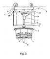
Figure 3 shows a side view of the lighting device inFigure 1 , yet without lateral cover, but 90 degrees rotated and fixed to a ceiling; -
Figure 4 is a block diagram of the system that allows an automatic aiming of the lighting device; and -
Figure 5 is a flowchart depicting the logic of the system with reference to the block diagram inFigure 4 . - First, reference is made to
Figures 1 to 3 , which are orthogonal views of an embodiment of the lighting device according to the invention, being an integral part of a scialytic lamp for operating-room. InFigures 1 to 3 , a fixed support element is indicated as 1, a frame as 2, and a movable lamp-holder denoted by 3 is in the form of a disk on which three lamps with reflectors and indicated generally as 4 are mounted at the same angular distance. Thefixed support element 1 is designed to be applied to a ceiling, as shown inFigure 3 , by means of screws indicated as 5. - The
frame 2 is designed to sustain an aiming mechanism for the movable lamp-holder 3. Driving means for moving the lamp-holder 3 with respect to thefixed support element 1 is part of the aiming mechanism. - With reference to
Figure 2 particularly, the driving means comprises anelectric motor 6 having a shaft to which adriving gear wheel 7, being meshed with a first drivengear wheel 8, is keyed. Suitably, thegear wheels gear wheel 9, having the same number of teeth and the same pitch of the first two gear wheels, is meshed with the first drivengear wheel 8 so that the second drivengear wheel 9 rotates at the same speed and in the same direction of thedriving gear wheel 7. The above described driving means are mounted to anupper plate 10 of theframe 2. Theframe 2 is shown as an open parallelepipedal construction, but obviously it is closed by suitable panels on its lateral surface. - Eccentrically pivoted to the first driven
gear wheel 8 is an end of arod 11, whose opposite end is pivoted to the lamp-holder disk 3 by means of a ball joint. Therod 11 is constrained to rotate, in a position between its ends, on alower plate 12 of theframe 2. - An
optical encoder 13, which is adapted to give the position of the movable lamp-holder, is mounted to the second drivengear wheel 9. - The
frame 2 is mounted to the supportingelement 1 through itsupper frame plate 10 by interposed vibration-damping pads, which are generally indicated as 14 and serve to damp vibrations generated by the motor and permit more accuracy of the light beam while it is moving. - Preferably, centrally mounted to the lamp-holder disk is an
optical sensor 15, whose function will be evident from the following of the description. - Referring to
Figure 4 , there is shown a block diagram of the aiming system, which the lighting device according to the present invention is provided with. Blocks are denoted by some of the reference numerals above cited, such as themotor 6, theoptical encoder 13 and theoptical sensor 15. Further, a micro-controller, which is indicated as 16, is connected to themotor 6 by apower amplifier 17 and to theoptical sensor 15 by anamplifier 18. Furthermore, apower source 19 is provided. - Now, driving means operates as follows. The
driving gear wheel 7, through the motion given by themotor 6 whose shaft supports keyed thedriving gear wheel 7, begins to move transmitting the movement to the drivengear wheel 8, that in turn will give the rotary movement also to therod 11, which has one end pivoted to the lamp-holder disk 3 and the other end pivoted to the drivengear wheel 8. The combination of the rotary movement of therod 11, which is constrained near the one end thereof, generates a rotation describing a cone in the space. Therod 11, being connected to the lamp-holder disk 3, will transmit this kind of movement also to the latter. Further the first drivengear wheel 8 has a double purpose: besides generating a conic-rotary movement, it transmits its rotation also to the second drivengear wheel 9, which in turn is connected to theoptical encoder 13. Preferably, the threegear wheels driving gear wheel 7 and the second drivengear wheel 9 for theencoder 13. In this way there is a biunivoc correspondence between the shaft of themotor 6 and theencoder 13, as they move always at the same rotation time and at the same speed. - Preferably, three 50
W halogen lamps 4 are mounted to the lamp-holder disk 3 according to the invention. These lamps project a spot onto a work plane situated at a distance of about two meters, the spot having such an intensity that it assures a brightness prescribed for a micro-precision operation. The lamps are mounted to the lamp-holder disk 3 with a determined angle toward the central axis of the lamp-holder disk 3 so that beams of the three lamps converge to a same point from a distance of two meters. The angle chosen is about 2 degrees, more precisely 1 degree 51 min 36 sec (0,0264 radian). - The mechanical design of the lamp-holder disk forces the spot being projected by the lamps to move along an elliptic trajectory, permitting to aim the light beam onto any point inside the ellipse by rotating the axis of the lamp-holder disk.
- In order to keep the aiming onto a target movable on a plane that is at a predetermined distance, the device must be interlocked to an automatic system able to locate the point in question and orient the lamps so that they illuminate it.
- The interlocking system of the device is schematised in
Figure 4 . - It comprises the direct-
current motor 6, having a power suitable to move the rotating lamp-holder disk 3, the amplifier/polarity inverter 17 to control themotor 6 and invert the running direction thereof, theoptical encoder 13 for the angular position, theoptical sensor 15 with thesignal amplifier 18, and finally an electronic card based on themicro-controller 16, i.e. a microprocessor that is specialised to control systems and is provided, on one chip, with all necessary resources as well as a real processing unit. - The
microprocessor 16 controls the position of the lamp-holder disk until it optimises the illumination of a concerned zone that must have a reflectance or reflection factor greater with respect to the rest of the scenery. Such a restraint is necessary since the system must distinguish the concerned zone from the rest of the scenery on the base of some parameter. Suitably, the value of the light reflection factor has been chosen as a distinguishing parameter. In practice, it is sufficient that the working field is clearer than the contour, that must have a darker colour. This parameter is usual in the operating rooms, where sheets are chosen of a dark colour, and also gloves of the operating surgeons are opaque. - The aiming system will search for the point with greater reflection factor on the working plane, and it will be a task of the user to make so that this condition is respected.
- A brightness feedback is furnished by the accurate
optical sensor 15, which is housed in the centre of the lamp-holder disk 3 and has a visual field that through a small-diameter eyepiece is reduced to a portion of the illuminated zone of about 15 cm in diameter, this portion being also centred with respect to the axis of the lamp-holder disk 3. An analog signal from theoptical sensor 15 is amplified in situ to limit electric noises and delivered through a shielded wire to an analog-digital converter inside the micro-controller. Such a converter serves to transform the brightness data item into a number, which is stored in an internal memory of the micro-controller. - The axis of the lamp-holder disk, which is keyed with the optical encoder with a mechanical ratio 1:1, allows the micro-controller to know the position of the rod in every moment. In this way, the micro-controller can store in its internal memory brightness data bound to the angular position of the lamp-
holder disk 3, position that is related univocally to an exact point of the working plane. This will permit the maximum brightness position to be found. In the system there is finally thesuitable power source 19, which furnishes voltages required by electronics and lamps, from the main voltage. - The logic of operation of the micro-controller, implemented in its internal program, is synthetized in the flowchart in
Figure 5 . - After initial set-up in a
start step 20, reset of theinternal variables 21, IN/OUT setting 22, and interruptactivation 23, themicro-controller 16 begins an acquisition procedure consisting of making a complete turn of the lamp-holder disk 3 (step 24) as well as acquiring brightness data of the framed scenery, which is divided into 256 sections. Brightness data item of every section is related to its angular position, by virtue of information provided by theoptical encoder 13. When the turn is finished, the micro-controller searches, in a string of data stored inside, the maximum brightness value (step 25), together with its angular position. On the base of the assumed condition, such a maximum value coincides with the zone in which there is the target to be illuminated, whereby the micro-controller, by operating the motor, positions the lamp-holder disk in the direction of this maximum value. The positioning movement follows an elliptic trajectory and the direction of rotation is calculated for following the shortest path. - However, it can happen in a
decision step 26 that the brightness measure performed during the turn does not contain the required information: this occurs for example when the lamps are switched off or the scenery does not present a sufficient contrast between clear and dark zones (the reflectance is almost uniform). In this case, the micro-controller detects the abnormal condition since, beside the maximum brightness value, it calculates also the minimum one, and if the difference does not exceed a pre-set value, the measure is deemed invalid and after 2 seconds it will be repeated (step 27). - In a case of correct acquisition, after the positioning on the target (step 28), the system gets into stand-by and performs periodically brightness measures in the point in order to verify the continue centring of the target in a two
second waiting step 29, to go to adecision step 30 where the question is if the target is centred, to astep 31 for performing a local research and to adecision step 32. - Really, if the light level goes down a determined threshold, which is calculated as a percent of the previously detected maximum value, a local research is performed to try to regain the centring. In practice the lamp-holder disk rotates by a small angle in a direction and then in the other one. If the maximum signal is retrieved the waiting step is reached again, otherwise all the procedure is repeated from the beginning. In order to accelerate times for centring again the target, the program implements a kind of "memory of the displacement". I.e. normally the system tries first clockwise and then counter-clockwise, but the priority is decided by experience, since the micro-controller remembers the previous displacement of the target.
- The micro-processor card is feed by the same voltage of the lamps (12V) and is provided with filters to suppress noises in the line. The motor is controlled by a power transistor (solid state device in order to prevent sparks) whereas the polarity inversion relay is activated always some tenth of second before starting the motor in order to prevent the formation of voltaic arches and the consequent wear of contacts, as well as for the compatibility of the operating-room, the compatibility being in any case assured as such a relay is sealed.
Claims (4)
- A lighting device provided with automatic aiming system, comprising a fixed supporting element (1) and a movable lamp-holder (3) holding light sources (4) that are fixed thereto, driving means adapted to move the movable lamp-holder (3) with respect to the fixed supporting element (1), a sensor and a micro-controller (16) which receives data from the sensor (15) and uses it to control the operation of said driving means in order to modify the position of the movable lamp-holder (3) and then the orientation of light beams thereof in the space, said sensor being an optical sensor (15) adapted to detect a reflectance factor of the light from an illuminated field for each position of the lamp-holder (3), the lighting device also including an optical encoder (13) able to provide the position of the movable lamp-holder (3) in every moment, the micro-controller (16) receiving from the optical sensor (15) data relevant to such a reflectance factor, and from the optical encoder (13) data relevant to the position of the movable lamp-holder (3) to control the operation of driving means for the constant aiming of a zone of the illuminated field which has a maximum reflectance factor, characterised in that said driving means comprises a motor (6) having a shaft to which is keyed a driving gear wheel (7), which is meshed with a first driven gear wheel (8), a second driven gear wheel (9) being mounted so to rotate at the same speed and in the same direction of the driving gear wheel (7).
- The device according to claim 1, characterised in that said driving means of the movable lamp-holder (3) comprises a rod (11), which is pivoted at one end thereof to the lamp-holder (3) and, at the other end thereof is pivoted eccentrically to said first driven gear wheel (8) and is constrained to rotate, in a position between its ends, on a lower plate (12) of the frame (2) which is connected to said fixed supporting element (1).
- The device according to claim 2, characterised in that said driving means are mounted to an upper plate (10) of said frame (2).
- The device according to claim 3, characterised in that said frame (2) is attached to said fixed supporting element (1) with the interposition of vibration-damping pads (14) applied to said upper plate (10).
Applications Claiming Priority (2)
| Application Number | Priority Date | Filing Date | Title |
|---|---|---|---|
| IT000039A ITNA20060039A1 (en) | 2006-03-29 | 2006-03-29 | LIGHTING EQUIPMENT EQUIPPED WITH AN AUTOMATIC AIMING SYSTEM |
| PCT/IT2007/000230 WO2007110895A1 (en) | 2006-03-29 | 2007-03-28 | Lighting device provided with automatic aiming system |
Publications (2)
| Publication Number | Publication Date |
|---|---|
| EP1999405A1 EP1999405A1 (en) | 2008-12-10 |
| EP1999405B1 true EP1999405B1 (en) | 2009-07-22 |
Family
ID=38236517
Family Applications (1)
| Application Number | Title | Priority Date | Filing Date |
|---|---|---|---|
| EP07736734A Not-in-force EP1999405B1 (en) | 2006-03-29 | 2007-03-28 | Lighting device provided with automatic aiming system |
Country Status (5)
| Country | Link |
|---|---|
| EP (1) | EP1999405B1 (en) |
| AT (1) | ATE437334T1 (en) |
| DE (1) | DE602007001687D1 (en) |
| IT (1) | ITNA20060039A1 (en) |
| WO (1) | WO2007110895A1 (en) |
Families Citing this family (3)
| Publication number | Priority date | Publication date | Assignee | Title |
|---|---|---|---|---|
| EP2017526A1 (en) * | 2007-06-13 | 2009-01-21 | Royal College Of Art | Directable light |
| JP2011522371A (en) | 2008-05-29 | 2011-07-28 | コーニンクレッカ フィリップス エレクトロニクス エヌ ヴィ | Control information that controls the lighting system |
| FR3052536B1 (en) | 2016-06-08 | 2018-06-01 | Maquet Sas | MEDICAL LIGHTING DEVICE WITH GOOD POSITIONING ASSISTING SYSTEM |
Family Cites Families (3)
| Publication number | Priority date | Publication date | Assignee | Title |
|---|---|---|---|---|
| DE3933596A1 (en) * | 1989-10-07 | 1991-04-18 | Heraeus Instr Gmbh | OPERATION LIGHT WITH ADJUSTABLE BRACKET |
| JP2506820Y2 (en) * | 1990-10-01 | 1996-08-14 | 山田医療照明株式会社 | Automatic focus position adjustment device for medical shadowless illumination device |
| DE20316756U1 (en) * | 2003-10-31 | 2005-03-17 | Leibinger Medizintech | Brightness controlled medical illumination device for working area of physician, especially operating area, has device for determining brightness in working area, device for regulating illumination intensity depending on brightness |
-
2006
- 2006-03-29 IT IT000039A patent/ITNA20060039A1/en unknown
-
2007
- 2007-03-28 WO PCT/IT2007/000230 patent/WO2007110895A1/en active Application Filing
- 2007-03-28 DE DE602007001687T patent/DE602007001687D1/en not_active Expired - Fee Related
- 2007-03-28 AT AT07736734T patent/ATE437334T1/en not_active IP Right Cessation
- 2007-03-28 EP EP07736734A patent/EP1999405B1/en not_active Not-in-force
Also Published As
| Publication number | Publication date |
|---|---|
| DE602007001687D1 (en) | 2009-09-03 |
| WO2007110895A1 (en) | 2007-10-04 |
| ATE437334T1 (en) | 2009-08-15 |
| ITNA20060039A1 (en) | 2007-09-30 |
| EP1999405A1 (en) | 2008-12-10 |
Similar Documents
| Publication | Publication Date | Title |
|---|---|---|
| US11864846B2 (en) | Bone and tool tracking in robotized computer-assisted surgery | |
| DK2434202T3 (en) | Operating lamp with sterile control device | |
| US8221399B2 (en) | Ophthalmic apparatus | |
| CN103403442B (en) | For illuminating surgery operating lamp and the method for surgery location | |
| US7284861B2 (en) | Ophthalmic apparatus and corneal surgery apparatus | |
| JPH03134901A (en) | Method of working luminaire for operation and luminaire for operation with adjustable holder | |
| CN105073054A (en) | Navigation system and method for indicating line of sight errors | |
| US7497019B2 (en) | Laser reference device | |
| US4578575A (en) | Operating theatre lamp | |
| WO2016114834A2 (en) | Actively controlled optical tracker with a robot | |
| US7275829B2 (en) | Ophthalmic laser irradiation apparatus | |
| JP2010514512A (en) | Apparatus and method for providing an adjustable positive stop in space | |
| ES2626123T3 (en) | Method to adjust the light source of an electronic alignment device | |
| EP1999405B1 (en) | Lighting device provided with automatic aiming system | |
| US6803727B2 (en) | Light system for use especially by operating theatre | |
| CA2899550A1 (en) | Lighting arrangement of operating theatre | |
| KR101708701B1 (en) | An Apparatus for Verifying a Surgical Site Automatically and a Method for Controlling a Light Automatically Using the Same | |
| CN109154433B (en) | Medical lighting device with system for assisting correct positioning | |
| EA027026B1 (en) | Lighting arrangement | |
| EP3906753B1 (en) | Control for adaptive lighting array | |
| JP3889997B2 (en) | Optometry equipment | |
| JPS6152850A (en) | Eyeball refraction force measuring apparatus | |
| JP3057553U (en) | Medical surgical light | |
| EP4006403A1 (en) | Ceiling-mounted lighting device | |
| JP2019502430A (en) | Beam guide for ophthalmic surgical lighting |
Legal Events
| Date | Code | Title | Description |
|---|---|---|---|
| PUAI | Public reference made under article 153(3) epc to a published international application that has entered the european phase |
Free format text: ORIGINAL CODE: 0009012 |
|
| 17P | Request for examination filed |
Effective date: 20080630 |
|
| AK | Designated contracting states |
Kind code of ref document: A1 Designated state(s): AT BE BG CH CY CZ DE DK EE ES FI FR GB GR HU IE IS IT LI LT LU LV MC MT NL PL PT RO SE SI SK TR |
|
| GRAP | Despatch of communication of intention to grant a patent |
Free format text: ORIGINAL CODE: EPIDOSNIGR1 |
|
| DAX | Request for extension of the european patent (deleted) | ||
| GRAS | Grant fee paid |
Free format text: ORIGINAL CODE: EPIDOSNIGR3 |
|
| GRAA | (expected) grant |
Free format text: ORIGINAL CODE: 0009210 |
|
| AK | Designated contracting states |
Kind code of ref document: B1 Designated state(s): AT BE BG CH CY CZ DE DK EE ES FI FR GB GR HU IE IS IT LI LT LU LV MC MT NL PL PT RO SE SI SK TR |
|
| REG | Reference to a national code |
Ref country code: GB Ref legal event code: FG4D |
|
| REG | Reference to a national code |
Ref country code: CH Ref legal event code: EP |
|
| REG | Reference to a national code |
Ref country code: IE Ref legal event code: FG4D |
|
| REF | Corresponds to: |
Ref document number: 602007001687 Country of ref document: DE Date of ref document: 20090903 Kind code of ref document: P |
|
| NLV1 | Nl: lapsed or annulled due to failure to fulfill the requirements of art. 29p and 29m of the patents act | ||
| PG25 | Lapsed in a contracting state [announced via postgrant information from national office to epo] |
Ref country code: LT Free format text: LAPSE BECAUSE OF FAILURE TO SUBMIT A TRANSLATION OF THE DESCRIPTION OR TO PAY THE FEE WITHIN THE PRESCRIBED TIME-LIMIT Effective date: 20090722 Ref country code: AT Free format text: LAPSE BECAUSE OF FAILURE TO SUBMIT A TRANSLATION OF THE DESCRIPTION OR TO PAY THE FEE WITHIN THE PRESCRIBED TIME-LIMIT Effective date: 20090722 Ref country code: SE Free format text: LAPSE BECAUSE OF FAILURE TO SUBMIT A TRANSLATION OF THE DESCRIPTION OR TO PAY THE FEE WITHIN THE PRESCRIBED TIME-LIMIT Effective date: 20090722 Ref country code: FI Free format text: LAPSE BECAUSE OF FAILURE TO SUBMIT A TRANSLATION OF THE DESCRIPTION OR TO PAY THE FEE WITHIN THE PRESCRIBED TIME-LIMIT Effective date: 20090722 Ref country code: IS Free format text: LAPSE BECAUSE OF FAILURE TO SUBMIT A TRANSLATION OF THE DESCRIPTION OR TO PAY THE FEE WITHIN THE PRESCRIBED TIME-LIMIT Effective date: 20091122 Ref country code: ES Free format text: LAPSE BECAUSE OF FAILURE TO SUBMIT A TRANSLATION OF THE DESCRIPTION OR TO PAY THE FEE WITHIN THE PRESCRIBED TIME-LIMIT Effective date: 20091102 |
|
| PG25 | Lapsed in a contracting state [announced via postgrant information from national office to epo] |
Ref country code: SI Free format text: LAPSE BECAUSE OF FAILURE TO SUBMIT A TRANSLATION OF THE DESCRIPTION OR TO PAY THE FEE WITHIN THE PRESCRIBED TIME-LIMIT Effective date: 20090722 Ref country code: PL Free format text: LAPSE BECAUSE OF FAILURE TO SUBMIT A TRANSLATION OF THE DESCRIPTION OR TO PAY THE FEE WITHIN THE PRESCRIBED TIME-LIMIT Effective date: 20090722 Ref country code: NL Free format text: LAPSE BECAUSE OF FAILURE TO SUBMIT A TRANSLATION OF THE DESCRIPTION OR TO PAY THE FEE WITHIN THE PRESCRIBED TIME-LIMIT Effective date: 20090722 Ref country code: LV Free format text: LAPSE BECAUSE OF FAILURE TO SUBMIT A TRANSLATION OF THE DESCRIPTION OR TO PAY THE FEE WITHIN THE PRESCRIBED TIME-LIMIT Effective date: 20090722 |
|
| PG25 | Lapsed in a contracting state [announced via postgrant information from national office to epo] |
Ref country code: PT Free format text: LAPSE BECAUSE OF FAILURE TO SUBMIT A TRANSLATION OF THE DESCRIPTION OR TO PAY THE FEE WITHIN THE PRESCRIBED TIME-LIMIT Effective date: 20091122 Ref country code: BG Free format text: LAPSE BECAUSE OF FAILURE TO SUBMIT A TRANSLATION OF THE DESCRIPTION OR TO PAY THE FEE WITHIN THE PRESCRIBED TIME-LIMIT Effective date: 20091022 |
|
| PG25 | Lapsed in a contracting state [announced via postgrant information from national office to epo] |
Ref country code: CZ Free format text: LAPSE BECAUSE OF FAILURE TO SUBMIT A TRANSLATION OF THE DESCRIPTION OR TO PAY THE FEE WITHIN THE PRESCRIBED TIME-LIMIT Effective date: 20090722 Ref country code: EE Free format text: LAPSE BECAUSE OF FAILURE TO SUBMIT A TRANSLATION OF THE DESCRIPTION OR TO PAY THE FEE WITHIN THE PRESCRIBED TIME-LIMIT Effective date: 20090722 Ref country code: RO Free format text: LAPSE BECAUSE OF FAILURE TO SUBMIT A TRANSLATION OF THE DESCRIPTION OR TO PAY THE FEE WITHIN THE PRESCRIBED TIME-LIMIT Effective date: 20090722 Ref country code: DK Free format text: LAPSE BECAUSE OF FAILURE TO SUBMIT A TRANSLATION OF THE DESCRIPTION OR TO PAY THE FEE WITHIN THE PRESCRIBED TIME-LIMIT Effective date: 20090722 |
|
| PLBE | No opposition filed within time limit |
Free format text: ORIGINAL CODE: 0009261 |
|
| STAA | Information on the status of an ep patent application or granted ep patent |
Free format text: STATUS: NO OPPOSITION FILED WITHIN TIME LIMIT |
|
| PG25 | Lapsed in a contracting state [announced via postgrant information from national office to epo] |
Ref country code: SK Free format text: LAPSE BECAUSE OF FAILURE TO SUBMIT A TRANSLATION OF THE DESCRIPTION OR TO PAY THE FEE WITHIN THE PRESCRIBED TIME-LIMIT Effective date: 20090722 Ref country code: BE Free format text: LAPSE BECAUSE OF FAILURE TO SUBMIT A TRANSLATION OF THE DESCRIPTION OR TO PAY THE FEE WITHIN THE PRESCRIBED TIME-LIMIT Effective date: 20090722 |
|
| 26N | No opposition filed |
Effective date: 20100423 |
|
| PG25 | Lapsed in a contracting state [announced via postgrant information from national office to epo] |
Ref country code: MC Free format text: LAPSE BECAUSE OF NON-PAYMENT OF DUE FEES Effective date: 20100331 Ref country code: GR Free format text: LAPSE BECAUSE OF FAILURE TO SUBMIT A TRANSLATION OF THE DESCRIPTION OR TO PAY THE FEE WITHIN THE PRESCRIBED TIME-LIMIT Effective date: 20091023 |
|
| REG | Reference to a national code |
Ref country code: FR Ref legal event code: ST Effective date: 20101130 |
|
| PG25 | Lapsed in a contracting state [announced via postgrant information from national office to epo] |
Ref country code: FR Free format text: LAPSE BECAUSE OF NON-PAYMENT OF DUE FEES Effective date: 20100331 Ref country code: IE Free format text: LAPSE BECAUSE OF NON-PAYMENT OF DUE FEES Effective date: 20100328 |
|
| PG25 | Lapsed in a contracting state [announced via postgrant information from national office to epo] |
Ref country code: DE Free format text: LAPSE BECAUSE OF NON-PAYMENT OF DUE FEES Effective date: 20101001 |
|
| PG25 | Lapsed in a contracting state [announced via postgrant information from national office to epo] |
Ref country code: IT Free format text: LAPSE BECAUSE OF FAILURE TO SUBMIT A TRANSLATION OF THE DESCRIPTION OR TO PAY THE FEE WITHIN THE PRESCRIBED TIME-LIMIT Effective date: 20090722 |
|
| PG25 | Lapsed in a contracting state [announced via postgrant information from national office to epo] |
Ref country code: MT Free format text: LAPSE BECAUSE OF FAILURE TO SUBMIT A TRANSLATION OF THE DESCRIPTION OR TO PAY THE FEE WITHIN THE PRESCRIBED TIME-LIMIT Effective date: 20090722 |
|
| REG | Reference to a national code |
Ref country code: GB Ref legal event code: 732E Free format text: REGISTERED BETWEEN 20110704 AND 20110706 |
|
| PGFP | Annual fee paid to national office [announced via postgrant information from national office to epo] |
Ref country code: GB Payment date: 20110513 Year of fee payment: 5 |
|
| REG | Reference to a national code |
Ref country code: CH Ref legal event code: PL |
|
| REG | Reference to a national code |
Ref country code: CH Ref legal event code: AEN Free format text: DAS PATENT IST AUFGRUND DES WEITERBEHANDLUNGSANTRAGS VOM 22.11.2011 REAKTIVIERT WORDEN. |
|
| PGFP | Annual fee paid to national office [announced via postgrant information from national office to epo] |
Ref country code: CH Payment date: 20111122 Year of fee payment: 5 |
|
| PG25 | Lapsed in a contracting state [announced via postgrant information from national office to epo] |
Ref country code: CY Free format text: LAPSE BECAUSE OF FAILURE TO SUBMIT A TRANSLATION OF THE DESCRIPTION OR TO PAY THE FEE WITHIN THE PRESCRIBED TIME-LIMIT Effective date: 20090722 |
|
| PG25 | Lapsed in a contracting state [announced via postgrant information from national office to epo] |
Ref country code: HU Free format text: LAPSE BECAUSE OF FAILURE TO SUBMIT A TRANSLATION OF THE DESCRIPTION OR TO PAY THE FEE WITHIN THE PRESCRIBED TIME-LIMIT Effective date: 20100123 Ref country code: LU Free format text: LAPSE BECAUSE OF NON-PAYMENT OF DUE FEES Effective date: 20100328 |
|
| PG25 | Lapsed in a contracting state [announced via postgrant information from national office to epo] |
Ref country code: TR Free format text: LAPSE BECAUSE OF FAILURE TO SUBMIT A TRANSLATION OF THE DESCRIPTION OR TO PAY THE FEE WITHIN THE PRESCRIBED TIME-LIMIT Effective date: 20090722 |
|
| REG | Reference to a national code |
Ref country code: CH Ref legal event code: PL |
|
| GBPC | Gb: european patent ceased through non-payment of renewal fee |
Effective date: 20120328 |
|
| PG25 | Lapsed in a contracting state [announced via postgrant information from national office to epo] |
Ref country code: GB Free format text: LAPSE BECAUSE OF NON-PAYMENT OF DUE FEES Effective date: 20120328 Ref country code: CH Free format text: LAPSE BECAUSE OF NON-PAYMENT OF DUE FEES Effective date: 20120331 Ref country code: LI Free format text: LAPSE BECAUSE OF NON-PAYMENT OF DUE FEES Effective date: 20120331 |