EP1999299B1 - Electro-chemical method in an enrichment process - Google Patents
Electro-chemical method in an enrichment process Download PDFInfo
- Publication number
- EP1999299B1 EP1999299B1 EP07730545.6A EP07730545A EP1999299B1 EP 1999299 B1 EP1999299 B1 EP 1999299B1 EP 07730545 A EP07730545 A EP 07730545A EP 1999299 B1 EP1999299 B1 EP 1999299B1
- Authority
- EP
- European Patent Office
- Prior art keywords
- current
- deposition
- protected
- potential
- power source
- Prior art date
- Legal status (The legal status is an assumption and is not a legal conclusion. Google has not performed a legal analysis and makes no representation as to the accuracy of the status listed.)
- Not-in-force
Links
- 238000000034 method Methods 0.000 title claims description 74
- 230000008569 process Effects 0.000 title claims description 43
- 238000002848 electrochemical method Methods 0.000 title 1
- 238000000151 deposition Methods 0.000 claims description 46
- 230000008021 deposition Effects 0.000 claims description 46
- 238000005259 measurement Methods 0.000 claims description 16
- 230000015572 biosynthetic process Effects 0.000 claims description 11
- 230000007797 corrosion Effects 0.000 claims description 9
- 238000005260 corrosion Methods 0.000 claims description 9
- 238000003487 electrochemical reaction Methods 0.000 claims description 7
- 229910052751 metal Inorganic materials 0.000 claims description 6
- 239000002184 metal Substances 0.000 claims description 6
- 230000010287 polarization Effects 0.000 claims description 6
- 239000003792 electrolyte Substances 0.000 claims description 5
- 239000000463 material Substances 0.000 claims description 5
- 239000007795 chemical reaction product Substances 0.000 claims description 4
- 230000008859 change Effects 0.000 claims description 2
- 150000002739 metals Chemical class 0.000 claims description 2
- 238000012544 monitoring process Methods 0.000 claims description 2
- 239000012716 precipitator Substances 0.000 claims description 2
- 229910001570 bauxite Inorganic materials 0.000 claims 1
- XLYOFNOQVPJJNP-UHFFFAOYSA-N water Substances O XLYOFNOQVPJJNP-UHFFFAOYSA-N 0.000 claims 1
- 230000001105 regulatory effect Effects 0.000 description 15
- 238000004131 Bayer process Methods 0.000 description 5
- 238000004519 manufacturing process Methods 0.000 description 5
- 239000000243 solution Substances 0.000 description 5
- 238000012360 testing method Methods 0.000 description 5
- 238000010586 diagram Methods 0.000 description 4
- 239000000523 sample Substances 0.000 description 4
- 239000000126 substance Substances 0.000 description 4
- 238000004140 cleaning Methods 0.000 description 3
- 238000002474 experimental method Methods 0.000 description 3
- 239000007787 solid Substances 0.000 description 3
- 229910000975 Carbon steel Inorganic materials 0.000 description 2
- 238000004458 analytical method Methods 0.000 description 2
- 239000010962 carbon steel Substances 0.000 description 2
- 238000000576 coating method Methods 0.000 description 2
- 238000002425 crystallisation Methods 0.000 description 2
- 230000008025 crystallization Effects 0.000 description 2
- 238000004090 dissolution Methods 0.000 description 2
- 230000009471 action Effects 0.000 description 1
- 239000012670 alkaline solution Substances 0.000 description 1
- 230000008901 benefit Effects 0.000 description 1
- 238000006243 chemical reaction Methods 0.000 description 1
- 239000011248 coating agent Substances 0.000 description 1
- 239000012141 concentrate Substances 0.000 description 1
- 230000000694 effects Effects 0.000 description 1
- 239000007772 electrode material Substances 0.000 description 1
- 238000004070 electrodeposition Methods 0.000 description 1
- 231100001261 hazardous Toxicity 0.000 description 1
- 230000006872 improvement Effects 0.000 description 1
- 230000002401 inhibitory effect Effects 0.000 description 1
- 238000005065 mining Methods 0.000 description 1
- 238000012986 modification Methods 0.000 description 1
- 230000004048 modification Effects 0.000 description 1
- 238000007254 oxidation reaction Methods 0.000 description 1
- TWNQGVIAIRXVLR-UHFFFAOYSA-N oxo(oxoalumanyloxy)alumane Chemical compound O=[Al]O[Al]=O TWNQGVIAIRXVLR-UHFFFAOYSA-N 0.000 description 1
- 239000002245 particle Substances 0.000 description 1
- 230000000737 periodic effect Effects 0.000 description 1
- 239000013074 reference sample Substances 0.000 description 1
- 229920006395 saturated elastomer Polymers 0.000 description 1
- 150000004760 silicates Chemical class 0.000 description 1
Images



Classifications
-
- C—CHEMISTRY; METALLURGY
- C23—COATING METALLIC MATERIAL; COATING MATERIAL WITH METALLIC MATERIAL; CHEMICAL SURFACE TREATMENT; DIFFUSION TREATMENT OF METALLIC MATERIAL; COATING BY VACUUM EVAPORATION, BY SPUTTERING, BY ION IMPLANTATION OR BY CHEMICAL VAPOUR DEPOSITION, IN GENERAL; INHIBITING CORROSION OF METALLIC MATERIAL OR INCRUSTATION IN GENERAL
- C23F—NON-MECHANICAL REMOVAL OF METALLIC MATERIAL FROM SURFACE; INHIBITING CORROSION OF METALLIC MATERIAL OR INCRUSTATION IN GENERAL; MULTI-STEP PROCESSES FOR SURFACE TREATMENT OF METALLIC MATERIAL INVOLVING AT LEAST ONE PROCESS PROVIDED FOR IN CLASS C23 AND AT LEAST ONE PROCESS COVERED BY SUBCLASS C21D OR C22F OR CLASS C25
- C23F14/00—Inhibiting incrustation in apparatus for heating liquids for physical or chemical purposes
-
- C—CHEMISTRY; METALLURGY
- C01—INORGANIC CHEMISTRY
- C01F—COMPOUNDS OF THE METALS BERYLLIUM, MAGNESIUM, ALUMINIUM, CALCIUM, STRONTIUM, BARIUM, RADIUM, THORIUM, OR OF THE RARE-EARTH METALS
- C01F7/00—Compounds of aluminium
- C01F7/02—Aluminium oxide; Aluminium hydroxide; Aluminates
- C01F7/04—Preparation of alkali metal aluminates; Aluminium oxide or hydroxide therefrom
- C01F7/06—Preparation of alkali metal aluminates; Aluminium oxide or hydroxide therefrom by treating aluminous minerals or waste-like raw materials with alkali hydroxide, e.g. leaching of bauxite according to the Bayer process
-
- C—CHEMISTRY; METALLURGY
- C23—COATING METALLIC MATERIAL; COATING MATERIAL WITH METALLIC MATERIAL; CHEMICAL SURFACE TREATMENT; DIFFUSION TREATMENT OF METALLIC MATERIAL; COATING BY VACUUM EVAPORATION, BY SPUTTERING, BY ION IMPLANTATION OR BY CHEMICAL VAPOUR DEPOSITION, IN GENERAL; INHIBITING CORROSION OF METALLIC MATERIAL OR INCRUSTATION IN GENERAL
- C23F—NON-MECHANICAL REMOVAL OF METALLIC MATERIAL FROM SURFACE; INHIBITING CORROSION OF METALLIC MATERIAL OR INCRUSTATION IN GENERAL; MULTI-STEP PROCESSES FOR SURFACE TREATMENT OF METALLIC MATERIAL INVOLVING AT LEAST ONE PROCESS PROVIDED FOR IN CLASS C23 AND AT LEAST ONE PROCESS COVERED BY SUBCLASS C21D OR C22F OR CLASS C25
- C23F13/00—Inhibiting corrosion of metals by anodic or cathodic protection
- C23F13/005—Anodic protection
-
- C—CHEMISTRY; METALLURGY
- C25—ELECTROLYTIC OR ELECTROPHORETIC PROCESSES; APPARATUS THEREFOR
- C25F—PROCESSES FOR THE ELECTROLYTIC REMOVAL OF MATERIALS FROM OBJECTS; APPARATUS THEREFOR
- C25F1/00—Electrolytic cleaning, degreasing, pickling or descaling
- C25F1/02—Pickling; Descaling
Definitions
- the present invention relates to a method as defined in the preamble of claim 1.
- Certain ore enrichment processes comprise dissolution of solid matter under high temperature and pressure conditions and a subsequent crystallization stage, from which the desired pure concentrate is obtained.
- the ore is dissolved in a hot alkaline solution under high pressure.
- a problem with these processes is fast formation of deposition on the surfaces of process equipment. Deposition is typically formed on the interior walls of dissolution reactors, concentrators and crystallizers because they are at a temperature lower than in the rest of the process: The solution close to the cooler surface becomes over-saturated with respect to a solids particle and the formation of deposition begins.
- the hard deposition formed on the surfaces mostly contains gibsite and various silicate compounds and is very difficult to remove. Due to the formation of deposition, pipes and valves get blocked, the efficiency of heat exchangers is reduced and the volume of tanks and containers and consequently the production capacity are reduced. For example, the volume of a crystallizer may be reduced by as much as one third, which in a crystallization process based on dwell time increases the delivery cycle time in a corresponding proportion, reducing the production quantities.
- the object of the present invention is to achieve an improvement in currently known deposition preventing methods used in mining industry.
- a more particular object of the invention is to create a method that will make it possible to alter the structure of especially the deposition formed in a Bayer process so as to prevent or considerably reduce its adherence to the surface of process equipment.
- a further object of the invention is to create a method that will retard the formation of deposition so that the length of the period between cleaning shutdowns can be substantially increased.
- the objects of the invention have to be achieved using an electro-chemical treatment that will not impair the corrosion resistance of the structural material of the process equipment to be protected against deposition.
- the method of the invention is based on the insight of using the effects resulting from the electro-chemical reactions taking place on and near the surface to alter the structure of the deposition so as to weaken its adherence to the surface.
- the surface of a process device in a process susceptible to deposition is polarized in the anodic direction by using an external power source and a current supply electrode placed in the solution so that the electro-chemical reaction products thus produced alter the structure of the deposition present or accumulating on the surface in such a way that the adherence of the deposition to the surface is substantially weakened.
- the change in the potential of the metal surface in the anodic direction caused by the anodic polarization is adapted to be such that the metal surface of the process device will not suffer corrosion damage due to the raised potential.
- the highest anodic potentials that can be used are determined by commonly known corrosion analysis methods and they depend on the properties of the electrolyte, the properties of the metal and the reference electrode used. Therefore, real-time measurement of the electro-chemical potential of the process device to be protected against deposition is important in respect of risk-free application of the method.
- the current/voltage supplied by the power source is controlled on the basis of an external measurement signal and/or an internal measurement signal.
- the current/voltage can be controlled on the basis of a control signal obtained from a data file.
- the current/voltage produced by the power source is controlled by means of a timed control signal so that the current/voltage is changed at desired time intervals t 1 , t 2 , ..., t n to a pre-desired magnitude.
- the surface of a process device in a process susceptible to deposition is polarized in the anodic direction by using an external power source and a current supply electrode placed in the solution so that the potential of the surface of the process device is brought to a range where the electro-chemical reactions provoked prevent the formation of deposition or substantially retard it.
- the potential has to be in a range where the structural material of the process device will not undergo corrosion damage.
- the surface of the process device to be protected need not be treated or coated with any special coating or a different kind of metal.
- the system of the invention is operated by supplying anodic current through the oxide layer that is spontaneously created in alkaline conditions on the surface of the commonest structural material, carbon steel, used in process equipment.
- the oxide layer is an important factor contributing to the corrosion resistance of carbon steel, so eliminating it e.g. from a cathode by using polarization is hazardous.
- Possible places where the system of the invention can be used include the inner walls, overflow chutes and process pipes of a process device, such as a precipitator, clarifier, crystallizer or reactor, in a process susceptible to deposition. Clogging of valves can also be obviated by the system of the invention.
- the current supply electrodes are mounted inside the process device so that they are in contact with the electrolyte and galvanically isolated from the process device to be protected.
- Reference electrodes monitoring the intensity of anodic polarization are mounted near the surface to be protected so that they are in contact with the electrolyte and galvanically isolated from the process device to be protected.
- the material of the reference electrodes can be selected from metals that can withstand the conditions prevailing in the process and retain their characteristic potential at a level sufficiently constant with respect to reliability of the potential measurement. The choice of the reference electrode material does not affect the working principle of the system of the invention.
- the method of the invention can be applied directly by installing in existing structures a system functioning according to the invention. If necessary, new structures can also be developed to allow application of the method of the invention.
- a process solution exposing equipment to the formation of deposition is indicated by reference number 10.
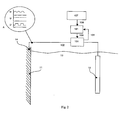
- the process device's metallic inner wall to be protected against deposition and functioning as one of the electrodes in an electric circuit is indicated by reference number 11, a current supply electrode by reference number 12, a reference electrode by reference number 13 and a galvanic anode current supply contact by reference number 14.
- the deposition layer in the immediate vicinity of the surface 11 is indicated by reference number 20 and an outer deposition layer by reference number 21.
- a power source 100 is fitted to supply the electrode pair 11, 12 either with direct current modified by an AC component, direct current or pulsed direct current, as visualized in magnified detail A.
- the current supply electrode 12 functions as a cathode while the inner wall 11 of metallic structure of the process device to be protected functions as an anode.
- the current supplied by the power source 100 is conducted via the cathode 12 through the process solution 10 serving as an electrolyte to the anode 11 to be protected against deposition and further via the galvanic contact 14 back to the power source 100.
- Placed near the object 11 to be protected against deposition is also a sensor, in this embodiment e.g. the reference electrode 13.
- the sensor 13 may be any detector that can provide the measuring and control unit 101 with information regarding the current state of the process susceptible to deposition.
- the measuring and control unit 101 controls the operation of the power source 100 via a control signal 106 so that a current of a desired magnitude flows between the electrode pair 11, 12, so that the oxidation reactions occurring on the surface of the object 11 to be protected are of a quantity and quality such that the reaction products formed as a result of the chemical reactions on the surface 11 and in its immediate vicinity inhibit the formation of deposition or substantially reduce the adherence of deposition to the object 11 to be protected.
- the current/voltage produced by the power source 100 is controlled by means of an external measurement signal 104 or an internal measurement signal 105.
- the current/voltage produced by the power source 100 can naturally also be controlled by means of an external measurement signal 104 and an internal measurement signal 105.
- the intensity of the current supplied by the power source 100 can also be controlled by only using a data file 107.
- the data received into the data file 107 includes e.g. information regarding a property of the process section preceding or following the process section susceptible to deposition that has been found to bear a correlation to the velocity of the formation of deposition or to the quality of the deposition.
- Information may also be supplied to the data file 107 from laboratory analyses. Such information includes e.g. the pH, solids content, temperature, concentration of a deposition component, viscosity, etc.
- the data file 107 also contains information regarding earlier current/voltage values produced by the power source 100 that have been found to be advantageous in respect of workability of the invention. From the data file 107, a control signal 108 is applied to the measuring and control unit 101.
- Fig. 3 presents a measurement result empirically obtained by applying a preferred embodiment of the method of the invention in a Bayer process.
- the duration of the experiment is represented as a number of days on the x-axis, while the y-axis represents the test sample area covered by deposition as a percentage of the total area of the test sample.
- Both the cathodically treated test sample and an untreated reference sample were completely covered by a deposition layer within 13...25 days from the beginning of the experiment.
- the surface area of the anodically treated test sample about one third was covered by deposition after a month from the beginning of the experiment, but after that the situation stabilized as the deposition began to detach spontaneously from the surface.
- the current densities with the test samples were about 0.5 - 20 A/m 2 , a pulsed direct current being used.
- Fig. 4 presents a flow diagram representing the regulating cycle performed by the control unit 101 to control the supply of current.
- the first step in the regulating cycle is measurement of the potential, whereupon it is possible to check whether the maximum potential which is of essential importance regarding the risk of corrosion has already been reached. Information regarding this corrosion risk potential may be pre-supplied, or it may be a value based on earlier measurements, or the sensor 13 may be provided with a system that together with the control unit 101 is able to perform on-line measurements for determining the corrosion risk potential. If it is established that the measured potential has already reached the allowed maximum limit, then the regulating cycle is terminated without further action.
- the next step is to check whether a target current or target potential defined in the regulating parameters has already been reached. If the target current or target potential has already been reached, then the regulating cycle is kept waiting until the end of the pulse duration, whereupon it is terminated. If the target current or target potential has not yet been reached, then the current or voltage supplied by the power source 100 is increased by a step of desired magnitude and the new potential is measured, whereupon the above-described checks are repeated. After the end of the regulating cycle, a new regulating cycle is started upon the lapse of a desired length of time.
- Fig. 5 presents a flow diagram representing the regulating cycle performed by the control unit 101 to control the supply of current when the control signal 106 received by the power source 100 can be calculated on the basis of the information contained in the data file 107.
- a measurement of the values to be fed into the data file 107 is performed.
- a calculated regulating parameter applicable to the situation is obtained from the data file 107 and the voltage or current supplied by the power source 100 is increased as desired.
- the regulating cycle is kept waiting until the end of the pulse duration and then terminated.
- a new regulating cycle is started upon the lapse of a desired length of time.
Landscapes
- Chemical & Material Sciences (AREA)
- Organic Chemistry (AREA)
- Engineering & Computer Science (AREA)
- Materials Engineering (AREA)
- Metallurgy (AREA)
- Mechanical Engineering (AREA)
- Life Sciences & Earth Sciences (AREA)
- General Life Sciences & Earth Sciences (AREA)
- Geochemistry & Mineralogy (AREA)
- Geology (AREA)
- Inorganic Chemistry (AREA)
- Chemical Kinetics & Catalysis (AREA)
- Electrochemistry (AREA)
- Testing Resistance To Weather, Investigating Materials By Mechanical Methods (AREA)
- Prevention Of Electric Corrosion (AREA)
Description
- The present invention relates to a method as defined in the preamble of claim 1.
- Certain ore enrichment processes comprise dissolution of solid matter under high temperature and pressure conditions and a subsequent crystallization stage, from which the desired pure concentrate is obtained. For example, in the Bayer process generally used in the production of aluminum oxide, the ore is dissolved in a hot alkaline solution under high pressure. A problem with these processes is fast formation of deposition on the surfaces of process equipment. Deposition is typically formed on the interior walls of dissolution reactors, concentrators and crystallizers because they are at a temperature lower than in the rest of the process: The solution close to the cooler surface becomes over-saturated with respect to a solids particle and the formation of deposition begins.
- In the Bayer process, the hard deposition formed on the surfaces mostly contains gibsite and various silicate compounds and is very difficult to remove. Due to the formation of deposition, pipes and valves get blocked, the efficiency of heat exchangers is reduced and the volume of tanks and containers and consequently the production capacity are reduced. For example, the volume of a crystallizer may be reduced by as much as one third, which in a crystallization process based on dwell time increases the delivery cycle time in a corresponding proportion, reducing the production quantities.
- Periodic cleaning shutdowns are required, and therefore a stand-by reserve of process equipment is needed; some of the equipment is always excluded from production due to cleaning. Thus, the highest costs result from production losses during shutdowns. Coatings more easily cleanable have been developed for process equipment. In addition, to restrain the formation of deposition, large quantities of different chemicals for preventing deposition are supplied into the process. Electro-chemical deposition inhibiting methods have also been proposed; for example, patent
CA2495957 describes an application of cathodic polarization. - The object of the present invention is to achieve an improvement in currently known deposition preventing methods used in mining industry. A more particular object of the invention is to create a method that will make it possible to alter the structure of especially the deposition formed in a Bayer process so as to prevent or considerably reduce its adherence to the surface of process equipment. A further object of the invention is to create a method that will retard the formation of deposition so that the length of the period between cleaning shutdowns can be substantially increased. In addition, the objects of the invention have to be achieved using an electro-chemical treatment that will not impair the corrosion resistance of the structural material of the process equipment to be protected against deposition.
- The objects of the invention are accomplished by a method according to claim 1.
- The method of the invention is based on the insight of using the effects resulting from the electro-chemical reactions taking place on and near the surface to alter the structure of the deposition so as to weaken its adherence to the surface.
- In a preferred embodiment of the invention, the surface of a process device in a process susceptible to deposition is polarized in the anodic direction by using an external power source and a current supply electrode placed in the solution so that the electro-chemical reaction products thus produced alter the structure of the deposition present or accumulating on the surface in such a way that the adherence of the deposition to the surface is substantially weakened. The change in the potential of the metal surface in the anodic direction caused by the anodic polarization is adapted to be such that the metal surface of the process device will not suffer corrosion damage due to the raised potential. The highest anodic potentials that can be used are determined by commonly known corrosion analysis methods and they depend on the properties of the electrolyte, the properties of the metal and the reference electrode used. Therefore, real-time measurement of the electro-chemical potential of the process device to be protected against deposition is important in respect of risk-free application of the method.
- In the method of the invention, the current/voltage supplied by the power source is controlled on the basis of an external measurement signal and/or an internal measurement signal. Alternatively, the current/voltage can be controlled on the basis of a control signal obtained from a data file.
- In a preferred embodiment of the method of the invention, the current/voltage produced by the power source is controlled by means of a timed control signal so that the current/voltage is changed at desired time intervals t1, t2, ..., tn to a pre-desired magnitude.
- In a second preferred embodiment of the invention, the surface of a process device in a process susceptible to deposition is polarized in the anodic direction by using an external power source and a current supply electrode placed in the solution so that the potential of the surface of the process device is brought to a range where the electro-chemical reactions provoked prevent the formation of deposition or substantially retard it. In this case, too, the potential has to be in a range where the structural material of the process device will not undergo corrosion damage.
- In the method of the invention, it is possible to use pulsed anodic direct current or a combination of an alternating-current component and an anodic direct-current component to produce the desired electro-chemical reactions.
- In the system of the invention, the surface of the process device to be protected need not be treated or coated with any special coating or a different kind of metal. The system of the invention is operated by supplying anodic current through the oxide layer that is spontaneously created in alkaline conditions on the surface of the commonest structural material, carbon steel, used in process equipment. The oxide layer is an important factor contributing to the corrosion resistance of carbon steel, so eliminating it e.g. from a cathode by using polarization is hazardous.
- Possible places where the system of the invention can be used include the inner walls, overflow chutes and process pipes of a process device, such as a precipitator, clarifier, crystallizer or reactor, in a process susceptible to deposition. Clogging of valves can also be obviated by the system of the invention. The current supply electrodes are mounted inside the process device so that they are in contact with the electrolyte and galvanically isolated from the process device to be protected.
- Reference electrodes monitoring the intensity of anodic polarization are mounted near the surface to be protected so that they are in contact with the electrolyte and galvanically isolated from the process device to be protected. The material of the reference electrodes can be selected from metals that can withstand the conditions prevailing in the process and retain their characteristic potential at a level sufficiently constant with respect to reliability of the potential measurement. The choice of the reference electrode material does not affect the working principle of the system of the invention.
- The method of the invention can be applied directly by installing in existing structures a system functioning according to the invention. If necessary, new structures can also be developed to allow application of the method of the invention.
- In the following, the invention will be described in detail by referring to a few preferred embodiments presented in the figures in the attached drawings, but the invention is not exclusively limited to those embodiments.
-
Fig. 1 represents a preferred embodiment of the method of the invention in diagrammatic side view. -
Fig. 2 represents a second preferred embodiment of the method of the invention in diagrammatic cross-sectional side view. -
Fig. 3 illustrates an advantage achieved by using the method of the invention in obviating deposition in a Bayer process. -
Fig. 4 presents a flow diagram representing the regulating function of a preferred embodiment of the method of the invention. -
Fig. 5 presents a flow diagram representing the regulating function of a second preferred embodiment of the method of the invention. - In
Fig. 1 , a process solution exposing equipment to the formation of deposition is indicated byreference number 10. In this embodiment, the process device's metallic inner wall to be protected against deposition and functioning as one of the electrodes in an electric circuit is indicated byreference number 11, a current supply electrode byreference number 12, a reference electrode byreference number 13 and a galvanic anode current supply contact byreference number 14. In magnified detail B, the deposition layer in the immediate vicinity of thesurface 11 is indicated byreference number 20 and an outer deposition layer byreference number 21. - In the embodiment according to
Fig. 1 , apower source 100 is fitted to supply theelectrode pair current supply electrode 12 functions as a cathode while theinner wall 11 of metallic structure of the process device to be protected functions as an anode. The current supplied by thepower source 100 is conducted via thecathode 12 through theprocess solution 10 serving as an electrolyte to theanode 11 to be protected against deposition and further via thegalvanic contact 14 back to thepower source 100. Placed near theobject 11 to be protected against deposition is also a sensor, in this embodiment e.g. thereference electrode 13. Thesensor 13 may be any detector that can provide the measuring andcontrol unit 101 with information regarding the current state of the process susceptible to deposition. The measuring andcontrol unit 101 controls the operation of thepower source 100 via acontrol signal 106 so that a current of a desired magnitude flows between theelectrode pair object 11 to be protected are of a quantity and quality such that the reaction products formed as a result of the chemical reactions on thesurface 11 and in its immediate vicinity inhibit the formation of deposition or substantially reduce the adherence of deposition to theobject 11 to be protected. Functionally, this appears e.g. as a process whereby thedeposition layer 20 closest to thesurface 11 is softened sufficiently to weaken its adhesion to thesurface 11 and the weight of theouter deposition layer 21 causes the deposition layers to come off the wall, as illustrated in magnified detail C. - In the embodiment illustrated in
Fig. 1 , the current/voltage produced by thepower source 100 is controlled by means of anexternal measurement signal 104 or aninternal measurement signal 105. The current/voltage produced by thepower source 100 can naturally also be controlled by means of anexternal measurement signal 104 and aninternal measurement signal 105. - In the embodiment illustrated in
Fig. 2 , the intensity of the current supplied by thepower source 100 can also be controlled by only using adata file 107. The data received into thedata file 107 includes e.g. information regarding a property of the process section preceding or following the process section susceptible to deposition that has been found to bear a correlation to the velocity of the formation of deposition or to the quality of the deposition. Information may also be supplied to thedata file 107 from laboratory analyses. Such information includes e.g. the pH, solids content, temperature, concentration of a deposition component, viscosity, etc. Thedata file 107 also contains information regarding earlier current/voltage values produced by thepower source 100 that have been found to be advantageous in respect of workability of the invention. From thedata file 107, acontrol signal 108 is applied to the measuring andcontrol unit 101. -
Fig. 3 presents a measurement result empirically obtained by applying a preferred embodiment of the method of the invention in a Bayer process. The duration of the experiment is represented as a number of days on the x-axis, while the y-axis represents the test sample area covered by deposition as a percentage of the total area of the test sample. Both the cathodically treated test sample and an untreated reference sample were completely covered by a deposition layer within 13...25 days from the beginning of the experiment. Of the surface area of the anodically treated test sample, about one third was covered by deposition after a month from the beginning of the experiment, but after that the situation stabilized as the deposition began to detach spontaneously from the surface. The current densities with the test samples were about 0.5 - 20 A/m2, a pulsed direct current being used. -
Fig. 4 presents a flow diagram representing the regulating cycle performed by thecontrol unit 101 to control the supply of current. When asensor 13 measuring the electro-chemical potential of thesurface 11 is in use, the first step in the regulating cycle is measurement of the potential, whereupon it is possible to check whether the maximum potential which is of essential importance regarding the risk of corrosion has already been reached. Information regarding this corrosion risk potential may be pre-supplied, or it may be a value based on earlier measurements, or thesensor 13 may be provided with a system that together with thecontrol unit 101 is able to perform on-line measurements for determining the corrosion risk potential. If it is established that the measured potential has already reached the allowed maximum limit, then the regulating cycle is terminated without further action. If the allowed maximum limit of the potential has not yet been reached, then the next step is to check whether a target current or target potential defined in the regulating parameters has already been reached. If the target current or target potential has already been reached, then the regulating cycle is kept waiting until the end of the pulse duration, whereupon it is terminated. If the target current or target potential has not yet been reached, then the current or voltage supplied by thepower source 100 is increased by a step of desired magnitude and the new potential is measured, whereupon the above-described checks are repeated. After the end of the regulating cycle, a new regulating cycle is started upon the lapse of a desired length of time. -
Fig. 5 presents a flow diagram representing the regulating cycle performed by thecontrol unit 101 to control the supply of current when thecontrol signal 106 received by thepower source 100 can be calculated on the basis of the information contained in the data file 107. At the beginning of the regulating cycle, in case this information concerns on-line conditions, a measurement of the values to be fed into the data file 107 is performed. Next, a calculated regulating parameter applicable to the situation is obtained from the data file 107 and the voltage or current supplied by thepower source 100 is increased as desired. After this, the regulating cycle is kept waiting until the end of the pulse duration and then terminated. After the termination of the regulating cycle, a new regulating cycle is started upon the lapse of a desired length of time. - In the foregoing, only a few preferred embodiments of the invention have been described. It is obvious to a person skilled in the art that numerous modifications may be made in them within the scope of the inventive concept presented in the claims.
Claims (11)
- Method in bauxite enrichment process taking place in water solutions, in which process undesirable depositions (20) are formed in process containers, piping and equipment and in which the surface (11) of an object to be protected in a process susceptible to deposition is polarized in the anodic direction by using an external power source (100) and a current supply electrode (12) placed in the solution, characterized in that using pulsed anodic direct current the potential of the surface (11) of the object to be protected is brought to a range in which the electro-chemical reaction products thus produced alter the structure of the deposition (20) present on the surface (11) of the object (11) to be protected or accumulating on said surface (11) in such a way that the adherence of said deposition (20) to said surface (11) is substantially weakened.
- Method according to claim 1, characterized in that the potential of the surface (11) of the object to be protected is brought to a range in which the electro-chemical reaction products formed inhibit the formation of deposition or substantially retard the formation of deposition on said surface (11).
- Method according to claim 1 or 2, characterized in that the change in the potential of the said surface (11) of the said object to be protected resulting from the aforesaid anodic polarization is caused to be such that the said surface (11) does not undergo any substantial corrosion damage due to the raised potential.
- Method according to any one of claims 1 - 3, characterized in that a combination of an alternating-current component and an anodic direct-current component is used in the method to accomplish the desired electro-chemical reactions.
- Method according to any one of claims 1 - 4, characterized in that a current density value in the range of 0.5 - 20 A/m2 is chosen.
- Method according to any one of claims 1 - 5, characterized in that the current/voltage supplied by the said power source (100) is controlled on the basis of an external measurement signal (104) and/or an internal measurement signal (105).
- Method according to any one of claims 1-5, characterized in that the current/voltage supplied by the said power source (100) is controlled on the basis of a control signal (108) obtained from a data file (107).
- Method according to any one of claims 1 - 5, characterized in that the current/voltage produced by the said power source (100) is controlled by means of a timed control signal by changing the current/voltage at desired time intervals t1, t2, ..., tn to a pre-desired magnitude.
- Method according to any one of claims 1 - 8, characterized in that the said surface (11) of the said object to be protected is selected from the group of: precipitators, clarifiers, crystallizers or inner walls of a reactor, heat exchangers, overflow chutes, process pipes and valves used in a process.
- Method according to any one of claims 1 - 9, characterized in that reference electrodes (13) monitoring the intensity of the anodic polarization are mounted near the surface (11) to be protected so that they are in contact with the electrolyte and galvanically isolated from the objects to be protected.
- Method according to claim 10, characterized in that the material of the aforesaid reference electrode (13) is selected from metals that withstand the conditions prevailing in the process and retain their characteristic potential at a level sufficiently constant in respect of reliability of the potential measurement.
Applications Claiming Priority (2)
| Application Number | Priority Date | Filing Date | Title |
|---|---|---|---|
| FI20060299A FI120545B (en) | 2006-03-29 | 2006-03-29 | Electrochemical process in an enrichment process |
| PCT/FI2007/000076 WO2007110469A1 (en) | 2006-03-29 | 2007-03-28 | Electro-chemical method in an enrichment process |
Publications (3)
| Publication Number | Publication Date |
|---|---|
| EP1999299A1 EP1999299A1 (en) | 2008-12-10 |
| EP1999299A4 EP1999299A4 (en) | 2012-01-25 |
| EP1999299B1 true EP1999299B1 (en) | 2014-04-30 |
Family
ID=36191971
Family Applications (1)
| Application Number | Title | Priority Date | Filing Date |
|---|---|---|---|
| EP07730545.6A Not-in-force EP1999299B1 (en) | 2006-03-29 | 2007-03-28 | Electro-chemical method in an enrichment process |
Country Status (7)
| Country | Link |
|---|---|
| US (1) | US20100224505A1 (en) |
| EP (1) | EP1999299B1 (en) |
| AU (1) | AU2007231304B2 (en) |
| BR (1) | BRPI0709775B1 (en) |
| CA (1) | CA2637103C (en) |
| FI (1) | FI120545B (en) |
| WO (1) | WO2007110469A1 (en) |
Families Citing this family (1)
| Publication number | Priority date | Publication date | Assignee | Title |
|---|---|---|---|---|
| CN115698677A (en) * | 2020-05-29 | 2023-02-03 | 明智增长投资私人有限公司 | Surface Corrosion Monitoring System |
Family Cites Families (10)
| Publication number | Priority date | Publication date | Assignee | Title |
|---|---|---|---|---|
| US1773275A (en) * | 1926-04-19 | 1930-08-19 | Griffin Watkins | Means and apparatus for removing and preventing scale incrustations |
| US4345981A (en) * | 1978-11-24 | 1982-08-24 | Diamond Shamrock Corporation | Anodically polarized surface for biofouling and scale control |
| US4256556A (en) * | 1978-11-24 | 1981-03-17 | Diamond Shamrock Corporation | Anodically polarized surface for biofouling and scale control |
| US4342981A (en) * | 1981-01-05 | 1982-08-03 | Emerson Electric Co. | Thermally actuatable electrical switch construction, conductive lead therefor and methods of making the same |
| US4627900A (en) * | 1982-08-27 | 1986-12-09 | Amax Inc. | Electrochemical dissolution and control of nickel sulfide scale |
| US4689127A (en) * | 1986-02-14 | 1987-08-25 | Monsanto Company | Control of anodic passivation systems |
| US4874487A (en) * | 1986-07-18 | 1989-10-17 | Raychem Corporation | Corrosion protection |
| US6814873B2 (en) * | 2002-07-22 | 2004-11-09 | Cytec Technology Corp. | Method of preventing or reducing aluminosilicate scale in a bayer process |
| US7147768B2 (en) * | 2002-08-15 | 2006-12-12 | Alcan International Limited | Electrochemical scale inhibition |
| JP3978144B2 (en) * | 2003-01-28 | 2007-09-19 | ホシザキ電機株式会社 | Electrolytic ion water generator |
-
2006
- 2006-03-29 FI FI20060299A patent/FI120545B/en not_active IP Right Cessation
-
2007
- 2007-03-28 AU AU2007231304A patent/AU2007231304B2/en not_active Ceased
- 2007-03-28 EP EP07730545.6A patent/EP1999299B1/en not_active Not-in-force
- 2007-03-28 CA CA2637103A patent/CA2637103C/en not_active Expired - Fee Related
- 2007-03-28 WO PCT/FI2007/000076 patent/WO2007110469A1/en not_active Ceased
- 2007-03-28 BR BRPI0709775-1A patent/BRPI0709775B1/en not_active IP Right Cessation
- 2007-03-28 US US12/294,771 patent/US20100224505A1/en not_active Abandoned
Also Published As
| Publication number | Publication date |
|---|---|
| CA2637103A1 (en) | 2007-10-04 |
| CA2637103C (en) | 2014-05-27 |
| FI120545B (en) | 2009-11-30 |
| BRPI0709775A2 (en) | 2011-07-26 |
| BRPI0709775B1 (en) | 2018-06-05 |
| EP1999299A1 (en) | 2008-12-10 |
| AU2007231304A1 (en) | 2007-10-04 |
| FI20060299L (en) | 2007-09-30 |
| EP1999299A4 (en) | 2012-01-25 |
| FI20060299A0 (en) | 2006-03-29 |
| WO2007110469A1 (en) | 2007-10-04 |
| US20100224505A1 (en) | 2010-09-09 |
| AU2007231304B2 (en) | 2011-09-22 |
Similar Documents
| Publication | Publication Date | Title |
|---|---|---|
| CA1256819A (en) | Process for reconditioning a used ammoniacal copper etching solution containing copper solute | |
| CA2413888A1 (en) | Corrosion control utilizing a hydrogen peroxide donor | |
| KR101304182B1 (en) | Electrochemical treatment of solutions containing hexavalent chromium | |
| US7147768B2 (en) | Electrochemical scale inhibition | |
| AU2007231304B2 (en) | Electro-chemical method in an enrichment process | |
| CA2861302C (en) | Controlled trivalent chromium pretreatment | |
| US20090057274A1 (en) | Electric discharge machine and electric discharge machining method | |
| AU748300B2 (en) | Removal of pollutants from effluents with electrochemical treatment | |
| JP2010540780A5 (en) | ||
| US8425751B1 (en) | Systems and methods for the electrodeposition of a nickel-cobalt alloy | |
| KR101219713B1 (en) | Method for conversion coating of electro -painting | |
| Postlethwaite | The control of erosion-corrosion in slurry pipelines | |
| US3147204A (en) | Anodic prevention of hydrogen embrittlement of metals | |
| JP2019148005A (en) | Apparatus for treating acidic treatment liquid, method for treating acidic treatment liquid, surface treatment system, and surface treatment method | |
| AU2021281699B2 (en) | Surface corrosion monitoring system | |
| WO2005001164A1 (en) | Power control for an electrically powered water treatment apparatus | |
| JP2006316330A (en) | Method and device for maintaining function of nitric acid solution for activating surface of plating stock | |
| Choi et al. | Electrolytic removal of Ag (I) in the liquid wastes generated from the mediated electrochemical oxidation process | |
| KR101620760B1 (en) | Appartus for magnesium chemical conversion treatment and method for magnesium chemical conversion treatment | |
| JPH10195699A (en) | Composition control method of iron plating solution for electroplating process | |
| Terryn et al. | AC Electrograining of Aluminium in Hydrochloric and Nitric Acid: a Comparative Study | |
| JP6560878B2 (en) | Waste liquid sulfur component removing apparatus and waste liquid sulfur component removing method | |
| KR970070253A (en) | Apparatus and method for controlling pH of electroplating solution of zinc chloride-iron (Zn-Fe) alloy of hydrochloric acid (Hcl) | |
| JPS58167783A (en) | Cathodic corrosion-proofness of aluminum material | |
| Leiro et al. | Electrochemical analysis of corrosion products from long-lasting atmospheric tests |
Legal Events
| Date | Code | Title | Description |
|---|---|---|---|
| PUAI | Public reference made under article 153(3) epc to a published international application that has entered the european phase |
Free format text: ORIGINAL CODE: 0009012 |
|
| 17P | Request for examination filed |
Effective date: 20080905 |
|
| AK | Designated contracting states |
Kind code of ref document: A1 Designated state(s): AT BE BG CH CY CZ DE DK EE ES FI FR GB GR HU IE IS IT LI LT LU LV MC MT NL PL PT RO SE SI SK TR |
|
| A4 | Supplementary search report drawn up and despatched |
Effective date: 20111228 |
|
| RIC1 | Information provided on ipc code assigned before grant |
Ipc: C23F 14/00 20060101AFI20111221BHEP Ipc: C25F 1/02 20060101ALI20111221BHEP Ipc: C23F 13/00 20060101ALI20111221BHEP Ipc: C01F 7/06 20060101ALI20111221BHEP |
|
| DAX | Request for extension of the european patent (deleted) | ||
| 17Q | First examination report despatched |
Effective date: 20130521 |
|
| GRAP | Despatch of communication of intention to grant a patent |
Free format text: ORIGINAL CODE: EPIDOSNIGR1 |
|
| INTG | Intention to grant announced |
Effective date: 20131031 |
|
| GRAS | Grant fee paid |
Free format text: ORIGINAL CODE: EPIDOSNIGR3 |
|
| GRAA | (expected) grant |
Free format text: ORIGINAL CODE: 0009210 |
|
| AK | Designated contracting states |
Kind code of ref document: B1 Designated state(s): AT BE BG CH CY CZ DE DK EE ES FI FR GB GR HU IE IS IT LI LT LU LV MC MT NL PL PT RO SE SI SK TR |
|
| REG | Reference to a national code |
Ref country code: GB Ref legal event code: FG4D Ref country code: CH Ref legal event code: EP |
|
| REG | Reference to a national code |
Ref country code: AT Ref legal event code: REF Ref document number: 665230 Country of ref document: AT Kind code of ref document: T Effective date: 20140515 |
|
| REG | Reference to a national code |
Ref country code: IE Ref legal event code: FG4D |
|
| REG | Reference to a national code |
Ref country code: DE Ref legal event code: R096 Ref document number: 602007036365 Country of ref document: DE Effective date: 20140605 |
|
| REG | Reference to a national code |
Ref country code: AT Ref legal event code: MK05 Ref document number: 665230 Country of ref document: AT Kind code of ref document: T Effective date: 20140430 |
|
| REG | Reference to a national code |
Ref country code: LT Ref legal event code: MG4D |
|
| REG | Reference to a national code |
Ref country code: NL Ref legal event code: VDEP Effective date: 20140430 |
|
| PG25 | Lapsed in a contracting state [announced via postgrant information from national office to epo] |
Ref country code: LT Free format text: LAPSE BECAUSE OF FAILURE TO SUBMIT A TRANSLATION OF THE DESCRIPTION OR TO PAY THE FEE WITHIN THE PRESCRIBED TIME-LIMIT Effective date: 20140430 Ref country code: NL Free format text: LAPSE BECAUSE OF FAILURE TO SUBMIT A TRANSLATION OF THE DESCRIPTION OR TO PAY THE FEE WITHIN THE PRESCRIBED TIME-LIMIT Effective date: 20140430 Ref country code: FI Free format text: LAPSE BECAUSE OF FAILURE TO SUBMIT A TRANSLATION OF THE DESCRIPTION OR TO PAY THE FEE WITHIN THE PRESCRIBED TIME-LIMIT Effective date: 20140430 Ref country code: GR Free format text: LAPSE BECAUSE OF FAILURE TO SUBMIT A TRANSLATION OF THE DESCRIPTION OR TO PAY THE FEE WITHIN THE PRESCRIBED TIME-LIMIT Effective date: 20140731 Ref country code: BG Free format text: LAPSE BECAUSE OF FAILURE TO SUBMIT A TRANSLATION OF THE DESCRIPTION OR TO PAY THE FEE WITHIN THE PRESCRIBED TIME-LIMIT Effective date: 20140730 Ref country code: CY Free format text: LAPSE BECAUSE OF FAILURE TO SUBMIT A TRANSLATION OF THE DESCRIPTION OR TO PAY THE FEE WITHIN THE PRESCRIBED TIME-LIMIT Effective date: 20140430 Ref country code: IS Free format text: LAPSE BECAUSE OF FAILURE TO SUBMIT A TRANSLATION OF THE DESCRIPTION OR TO PAY THE FEE WITHIN THE PRESCRIBED TIME-LIMIT Effective date: 20140830 |
|
| PG25 | Lapsed in a contracting state [announced via postgrant information from national office to epo] |
Ref country code: SE Free format text: LAPSE BECAUSE OF FAILURE TO SUBMIT A TRANSLATION OF THE DESCRIPTION OR TO PAY THE FEE WITHIN THE PRESCRIBED TIME-LIMIT Effective date: 20140430 Ref country code: LV Free format text: LAPSE BECAUSE OF FAILURE TO SUBMIT A TRANSLATION OF THE DESCRIPTION OR TO PAY THE FEE WITHIN THE PRESCRIBED TIME-LIMIT Effective date: 20140430 Ref country code: PL Free format text: LAPSE BECAUSE OF FAILURE TO SUBMIT A TRANSLATION OF THE DESCRIPTION OR TO PAY THE FEE WITHIN THE PRESCRIBED TIME-LIMIT Effective date: 20140430 Ref country code: AT Free format text: LAPSE BECAUSE OF FAILURE TO SUBMIT A TRANSLATION OF THE DESCRIPTION OR TO PAY THE FEE WITHIN THE PRESCRIBED TIME-LIMIT Effective date: 20140430 Ref country code: ES Free format text: LAPSE BECAUSE OF FAILURE TO SUBMIT A TRANSLATION OF THE DESCRIPTION OR TO PAY THE FEE WITHIN THE PRESCRIBED TIME-LIMIT Effective date: 20140430 |
|
| PG25 | Lapsed in a contracting state [announced via postgrant information from national office to epo] |
Ref country code: PT Free format text: LAPSE BECAUSE OF FAILURE TO SUBMIT A TRANSLATION OF THE DESCRIPTION OR TO PAY THE FEE WITHIN THE PRESCRIBED TIME-LIMIT Effective date: 20140901 |
|
| PG25 | Lapsed in a contracting state [announced via postgrant information from national office to epo] |
Ref country code: EE Free format text: LAPSE BECAUSE OF FAILURE TO SUBMIT A TRANSLATION OF THE DESCRIPTION OR TO PAY THE FEE WITHIN THE PRESCRIBED TIME-LIMIT Effective date: 20140430 Ref country code: SK Free format text: LAPSE BECAUSE OF FAILURE TO SUBMIT A TRANSLATION OF THE DESCRIPTION OR TO PAY THE FEE WITHIN THE PRESCRIBED TIME-LIMIT Effective date: 20140430 Ref country code: BE Free format text: LAPSE BECAUSE OF FAILURE TO SUBMIT A TRANSLATION OF THE DESCRIPTION OR TO PAY THE FEE WITHIN THE PRESCRIBED TIME-LIMIT Effective date: 20140430 Ref country code: DK Free format text: LAPSE BECAUSE OF FAILURE TO SUBMIT A TRANSLATION OF THE DESCRIPTION OR TO PAY THE FEE WITHIN THE PRESCRIBED TIME-LIMIT Effective date: 20140430 Ref country code: RO Free format text: LAPSE BECAUSE OF FAILURE TO SUBMIT A TRANSLATION OF THE DESCRIPTION OR TO PAY THE FEE WITHIN THE PRESCRIBED TIME-LIMIT Effective date: 20140430 Ref country code: CZ Free format text: LAPSE BECAUSE OF FAILURE TO SUBMIT A TRANSLATION OF THE DESCRIPTION OR TO PAY THE FEE WITHIN THE PRESCRIBED TIME-LIMIT Effective date: 20140430 |
|
| REG | Reference to a national code |
Ref country code: DE Ref legal event code: R097 Ref document number: 602007036365 Country of ref document: DE |
|
| PLBE | No opposition filed within time limit |
Free format text: ORIGINAL CODE: 0009261 |
|
| STAA | Information on the status of an ep patent application or granted ep patent |
Free format text: STATUS: NO OPPOSITION FILED WITHIN TIME LIMIT |
|
| PG25 | Lapsed in a contracting state [announced via postgrant information from national office to epo] |
Ref country code: IT Free format text: LAPSE BECAUSE OF FAILURE TO SUBMIT A TRANSLATION OF THE DESCRIPTION OR TO PAY THE FEE WITHIN THE PRESCRIBED TIME-LIMIT Effective date: 20140430 |
|
| 26N | No opposition filed |
Effective date: 20150202 |
|
| REG | Reference to a national code |
Ref country code: DE Ref legal event code: R097 Ref document number: 602007036365 Country of ref document: DE Effective date: 20150202 |
|
| PG25 | Lapsed in a contracting state [announced via postgrant information from national office to epo] |
Ref country code: SI Free format text: LAPSE BECAUSE OF FAILURE TO SUBMIT A TRANSLATION OF THE DESCRIPTION OR TO PAY THE FEE WITHIN THE PRESCRIBED TIME-LIMIT Effective date: 20140430 |
|
| REG | Reference to a national code |
Ref country code: DE Ref legal event code: R119 Ref document number: 602007036365 Country of ref document: DE |
|
| PG25 | Lapsed in a contracting state [announced via postgrant information from national office to epo] |
Ref country code: MC Free format text: LAPSE BECAUSE OF FAILURE TO SUBMIT A TRANSLATION OF THE DESCRIPTION OR TO PAY THE FEE WITHIN THE PRESCRIBED TIME-LIMIT Effective date: 20140430 Ref country code: LU Free format text: LAPSE BECAUSE OF FAILURE TO SUBMIT A TRANSLATION OF THE DESCRIPTION OR TO PAY THE FEE WITHIN THE PRESCRIBED TIME-LIMIT Effective date: 20150328 |
|
| REG | Reference to a national code |
Ref country code: CH Ref legal event code: PL |
|
| GBPC | Gb: european patent ceased through non-payment of renewal fee |
Effective date: 20150328 |
|
| REG | Reference to a national code |
Ref country code: FR Ref legal event code: ST Effective date: 20151130 |
|
| PG25 | Lapsed in a contracting state [announced via postgrant information from national office to epo] |
Ref country code: CH Free format text: LAPSE BECAUSE OF NON-PAYMENT OF DUE FEES Effective date: 20150331 Ref country code: DE Free format text: LAPSE BECAUSE OF NON-PAYMENT OF DUE FEES Effective date: 20151001 Ref country code: LI Free format text: LAPSE BECAUSE OF NON-PAYMENT OF DUE FEES Effective date: 20150331 Ref country code: GB Free format text: LAPSE BECAUSE OF NON-PAYMENT OF DUE FEES Effective date: 20150328 |
|
| PG25 | Lapsed in a contracting state [announced via postgrant information from national office to epo] |
Ref country code: FR Free format text: LAPSE BECAUSE OF NON-PAYMENT OF DUE FEES Effective date: 20150331 |
|
| PG25 | Lapsed in a contracting state [announced via postgrant information from national office to epo] |
Ref country code: MT Free format text: LAPSE BECAUSE OF FAILURE TO SUBMIT A TRANSLATION OF THE DESCRIPTION OR TO PAY THE FEE WITHIN THE PRESCRIBED TIME-LIMIT Effective date: 20140430 |
|
| PG25 | Lapsed in a contracting state [announced via postgrant information from national office to epo] |
Ref country code: HU Free format text: LAPSE BECAUSE OF FAILURE TO SUBMIT A TRANSLATION OF THE DESCRIPTION OR TO PAY THE FEE WITHIN THE PRESCRIBED TIME-LIMIT; INVALID AB INITIO Effective date: 20070328 |
|
| PG25 | Lapsed in a contracting state [announced via postgrant information from national office to epo] |
Ref country code: TR Free format text: LAPSE BECAUSE OF FAILURE TO SUBMIT A TRANSLATION OF THE DESCRIPTION OR TO PAY THE FEE WITHIN THE PRESCRIBED TIME-LIMIT Effective date: 20140430 |
|
| PGFP | Annual fee paid to national office [announced via postgrant information from national office to epo] |
Ref country code: IE Payment date: 20190322 Year of fee payment: 13 |
|
| PG25 | Lapsed in a contracting state [announced via postgrant information from national office to epo] |
Ref country code: IE Free format text: LAPSE BECAUSE OF NON-PAYMENT OF DUE FEES Effective date: 20200328 |