EP1998868B1 - Method and means for simultaneously generating an aqueous froth and numerous micro-droplets for use in filtering a contaminated air stream - Google Patents
Method and means for simultaneously generating an aqueous froth and numerous micro-droplets for use in filtering a contaminated air stream Download PDFInfo
- Publication number
- EP1998868B1 EP1998868B1 EP07835717.5A EP07835717A EP1998868B1 EP 1998868 B1 EP1998868 B1 EP 1998868B1 EP 07835717 A EP07835717 A EP 07835717A EP 1998868 B1 EP1998868 B1 EP 1998868B1
- Authority
- EP
- European Patent Office
- Prior art keywords
- air stream
- mesh
- froth
- droplets
- contaminated air
- Prior art date
- Legal status (The legal status is an assumption and is not a legal conclusion. Google has not performed a legal analysis and makes no representation as to the accuracy of the status listed.)
- Active
Links
- 238000001914 filtration Methods 0.000 title claims description 122
- 238000000034 method Methods 0.000 title claims description 11
- 229920006395 saturated elastomer Polymers 0.000 claims description 43
- 239000000356 contaminant Substances 0.000 claims description 42
- 238000000429 assembly Methods 0.000 claims description 40
- 230000000712 assembly Effects 0.000 claims description 40
- 229910001220 stainless steel Inorganic materials 0.000 claims description 26
- 239000010935 stainless steel Substances 0.000 claims description 26
- 239000002245 particle Substances 0.000 claims description 16
- 230000009172 bursting Effects 0.000 claims description 9
- 238000004581 coalescence Methods 0.000 claims description 9
- 238000009792 diffusion process Methods 0.000 claims description 7
- 238000002407 reforming Methods 0.000 claims description 3
- 230000002250 progressing effect Effects 0.000 claims 2
- 238000009738 saturating Methods 0.000 claims 2
- 239000007921 spray Substances 0.000 description 37
- 239000003595 mist Substances 0.000 description 32
- 238000009826 distribution Methods 0.000 description 28
- 239000000443 aerosol Substances 0.000 description 21
- 238000005202 decontamination Methods 0.000 description 20
- 230000003588 decontaminative effect Effects 0.000 description 20
- 239000000835 fiber Substances 0.000 description 19
- 239000003507 refrigerant Substances 0.000 description 16
- 230000001133 acceleration Effects 0.000 description 11
- 230000005484 gravity Effects 0.000 description 11
- 239000003795 chemical substances by application Substances 0.000 description 9
- 239000012530 fluid Substances 0.000 description 9
- 230000006911 nucleation Effects 0.000 description 8
- 238000010899 nucleation Methods 0.000 description 8
- 125000006850 spacer group Chemical group 0.000 description 8
- 230000007704 transition Effects 0.000 description 8
- 238000001816 cooling Methods 0.000 description 7
- 230000002209 hydrophobic effect Effects 0.000 description 6
- 238000001228 spectrum Methods 0.000 description 6
- 230000005653 Brownian motion process Effects 0.000 description 5
- 238000005537 brownian motion Methods 0.000 description 5
- 238000009833 condensation Methods 0.000 description 5
- 230000005494 condensation Effects 0.000 description 5
- 239000007789 gas Substances 0.000 description 5
- 238000012546 transfer Methods 0.000 description 5
- 238000003491 array Methods 0.000 description 4
- 230000008901 benefit Effects 0.000 description 4
- 230000015572 biosynthetic process Effects 0.000 description 4
- 230000000694 effects Effects 0.000 description 4
- 239000006260 foam Substances 0.000 description 4
- 239000011159 matrix material Substances 0.000 description 4
- 239000000126 substance Substances 0.000 description 4
- 238000011144 upstream manufacturing Methods 0.000 description 4
- 241000193738 Bacillus anthracis Species 0.000 description 3
- 239000007788 liquid Substances 0.000 description 3
- 238000004519 manufacturing process Methods 0.000 description 3
- 239000002184 metal Substances 0.000 description 3
- 229910052751 metal Inorganic materials 0.000 description 3
- WYTGDNHDOZPMIW-RCBQFDQVSA-N alstonine Natural products C1=CC2=C3C=CC=CC3=NC2=C2N1C[C@H]1[C@H](C)OC=C(C(=O)OC)[C@H]1C2 WYTGDNHDOZPMIW-RCBQFDQVSA-N 0.000 description 2
- 230000000975 bioactive effect Effects 0.000 description 2
- 238000004891 communication Methods 0.000 description 2
- 230000002498 deadly effect Effects 0.000 description 2
- 238000005516 engineering process Methods 0.000 description 2
- 231100001261 hazardous Toxicity 0.000 description 2
- 239000003317 industrial substance Substances 0.000 description 2
- 238000011160 research Methods 0.000 description 2
- 238000012216 screening Methods 0.000 description 2
- 229910052815 sulfur oxide Inorganic materials 0.000 description 2
- 231100000331 toxic Toxicity 0.000 description 2
- 230000002588 toxic effect Effects 0.000 description 2
- 239000013598 vector Substances 0.000 description 2
- UGFAIRIUMAVXCW-UHFFFAOYSA-N Carbon monoxide Chemical compound [O+]#[C-] UGFAIRIUMAVXCW-UHFFFAOYSA-N 0.000 description 1
- 239000002253 acid Substances 0.000 description 1
- 239000012298 atmosphere Substances 0.000 description 1
- 239000003124 biologic agent Substances 0.000 description 1
- 230000005587 bubbling Effects 0.000 description 1
- 239000002575 chemical warfare agent Substances 0.000 description 1
- 238000011109 contamination Methods 0.000 description 1
- 238000013461 design Methods 0.000 description 1
- 238000011161 development Methods 0.000 description 1
- 230000008030 elimination Effects 0.000 description 1
- 238000003379 elimination reaction Methods 0.000 description 1
- 239000011152 fibreglass Substances 0.000 description 1
- 239000003546 flue gas Substances 0.000 description 1
- 239000012634 fragment Substances 0.000 description 1
- -1 i.e. Substances 0.000 description 1
- 230000006872 improvement Effects 0.000 description 1
- 230000003993 interaction Effects 0.000 description 1
- 239000000463 material Substances 0.000 description 1
- 230000007246 mechanism Effects 0.000 description 1
- 150000002739 metals Chemical class 0.000 description 1
- 239000000203 mixture Substances 0.000 description 1
- 238000012986 modification Methods 0.000 description 1
- 230000004048 modification Effects 0.000 description 1
- 230000037361 pathway Effects 0.000 description 1
- 230000000737 periodic effect Effects 0.000 description 1
- 230000008569 process Effects 0.000 description 1
- 238000005201 scrubbing Methods 0.000 description 1
- 238000004513 sizing Methods 0.000 description 1
- XTQHKBHJIVJGKJ-UHFFFAOYSA-N sulfur monoxide Chemical class S=O XTQHKBHJIVJGKJ-UHFFFAOYSA-N 0.000 description 1
- XLYOFNOQVPJJNP-UHFFFAOYSA-N water Substances O XLYOFNOQVPJJNP-UHFFFAOYSA-N 0.000 description 1
Images


Classifications
-
- B—PERFORMING OPERATIONS; TRANSPORTING
- B01—PHYSICAL OR CHEMICAL PROCESSES OR APPARATUS IN GENERAL
- B01D—SEPARATION
- B01D47/00—Separating dispersed particles from gases, air or vapours by liquid as separating agent
- B01D47/04—Separating dispersed particles from gases, air or vapours by liquid as separating agent by passing the gas or air or vapour through foam
-
- B—PERFORMING OPERATIONS; TRANSPORTING
- B01—PHYSICAL OR CHEMICAL PROCESSES OR APPARATUS IN GENERAL
- B01D—SEPARATION
- B01D50/00—Combinations of methods or devices for separating particles from gases or vapours
- B01D50/40—Combinations of devices covered by groups B01D45/00 and B01D47/00
-
- B—PERFORMING OPERATIONS; TRANSPORTING
- B01—PHYSICAL OR CHEMICAL PROCESSES OR APPARATUS IN GENERAL
- B01D—SEPARATION
- B01D50/00—Combinations of methods or devices for separating particles from gases or vapours
- B01D50/60—Combinations of devices covered by groups B01D46/00 and B01D47/00
-
- B—PERFORMING OPERATIONS; TRANSPORTING
- B01—PHYSICAL OR CHEMICAL PROCESSES OR APPARATUS IN GENERAL
- B01D—SEPARATION
- B01D53/00—Separation of gases or vapours; Recovering vapours of volatile solvents from gases; Chemical or biological purification of waste gases, e.g. engine exhaust gases, smoke, fumes, flue gases, aerosols
- B01D53/14—Separation of gases or vapours; Recovering vapours of volatile solvents from gases; Chemical or biological purification of waste gases, e.g. engine exhaust gases, smoke, fumes, flue gases, aerosols by absorption
- B01D53/18—Absorbing units; Liquid distributors therefor
- B01D53/185—Liquid distributors
Definitions
- the present invention relates generally to an aqueous froth air filter. More particularly, the present invention provides a significant improvement over my U.S. patents 6,616,733 and 6,872,240 , in the manner of generating the aqueous froth and micro-droplets used to accomplish the filtering of a contaminated air stream.
- US 4,925,462 describes apparatus for removing organochemical components from a gas.
- DE 3724099 discloses a gas-foam scrubbing unit.
- US 3,231,251 discloses a countercurrent gas-liquid contacting column wherein froth is formed from gas bubbling up through porous trays containing liquid.
- the '733 patent teaches a system which occasionally generates a froth that includes an excessive percentage of large bubbles in the froth, which detract from the overall filtering performance, as described below.
- the '240 patent teaches a system wherein micro-droplets are added to the aqueous froth by a series of fogger nozzles. The numerous micro-droplets contribute to the overall effectiveness of the system, but require the use of an air compressor with a fogger nozzle array. The nozzle array is subject to periodic fouling of nozzles and the air compressor is subject to failure, reducing overall filtering efficiency.
- the present invention overcomes the above-described problems with the prior art and, in addition, provides considerably higher overall filtering efficiency.
- the present invention essentially eliminates the generation of unduly large bubbles (the main weakness of the '733 patent) in part by using a series of saturated mesh panels wherein the mesh openings are small and prevent formation of large bubbles. Large bubbles are also prevented in the present invention by the deliberate bursting of bubbles.
- the present invention also eliminates the array of fogger nozzles and air compressor required by the '240 patent, while still achieving the generation of micro-droplets which cooperate with the aqueous froth.
- the present invention generates a much wider micro-droplet diameter and mass distribution than the prior art array of fogger nozzles.
- Micro-dropfets of different diameter and mass have different momentum in the moving air stream, facilitating collision coalescence between micro-droplets, and removal from the air stream by inertial impaction on the surfaces of the filter.
- the enormous number of micro-droplets generated by the present invention is achieved by intentionally causing the aqueous froth bubbles to burst and reform between and downstream of each saturated mesh assembly. As the bubbles are intentionally caused to burst, each bursting bubble ruptures into hundreds or thousands of micro-droplets. These micro-droplets are used downstream in the system to coalesce with or to otherwise bind with contaminants in the air stream, and then to remove those contaminants from the air stream.
- the array of saturated mesh assemblies of the present invention generates an aqueous froth having uniformly small bubbles, which enables a high level of filtering efficiency. Simultaneously, the array of saturated mesh assemblies, interacting with the contaminated air stream flowing therethrough, causes bursting and reforming of bubbles preferably two or more times, creating an extremely large number of micro-droplets to interact with contaminants.
- An optional aspect of the invention is to separately filter large particles of contaminant, i.e., particles greater than 3 microns in diameter. These large particles are separated by momentarily increasing the velocity of the contaminated air stream before the air stream encounters the aqueous froth. While the air stream velocity is momentarily increased, these large particles are removed by "inertial impaction," i.e., contact with a high efficiency filter.
- the present invention is uniquely capable of filtering biological and chemical warfare agents, such as anthrax spores and other deadly agents, from the air stream.
- Decontamination foams have been developed to kill anthrax spores and many other deadly agents, after those agents have contacted walls and floors and contaminated a building.
- the present invention acts as a safeguard in the HVAC system to filter out and kill the anthrax spores, for example, prior to contamination of the walls and floors of the building!
- the present invention may also be used as an industrial filter for removing a variety of contaminants in numerous industrial applications.
- a primary object of the invention is to provide a method and apparatus for increasing the overall filtering efficiency of an aqueous froth filter.
- a further object of the invention is to provide an aqueous froth filter which simultaneously generates a froth having relatively uniformly small bubbles and which also generates numerous micro-droplets of different radii, both of which enhance the overall efficiency of the filtering system.
- a further object of the invention is to provide an array of spaced apart saturated mesh assemblies which interact with a contaminated air stream to simultaneously generate a froth having a relatively uniform size of small bubbles and generate numerous micro-droplets of different radii, both of which significantly increase filtering efficiency.
- a further object is to provide a high efficiency aqueous froth filter capable of filtering chemical and biological warfare agents from a contaminated air stream.
- Another object is to provide a high efficiency aqueous froth filter capable of filtering a variety of contaminated, industrially created air streams.
- a further object is to increase overall filtering efficiency of an aqueous froth filter by momentarily increasing the velocity of the contaminated air stream to separately filter large particles by inertial impaction.
- a further object is to increase overall filtering efficiency of an aqueous froth filter by momentarily reducing the velocity of the contaminated air stream to separately filter less massive particles by diffusion.
- Figs. 1A and 1B in exemplary form as an improved means of generating an aqueous froth and introducing a wide-spectrum of filtering or decontamination solution droplet radii into a contaminated air stream for a high-efficiency sub-micrometer aerosol filtration device to remove, sequester, and kill biological warfare (BW) agent aerosols, and to remove, sequester, and neutralize chemical warfare (CW) agent aerosols and gasses.
- Fig. 1A is a side view, partially in section, of the preferred embodiment of the froth generator (which also generates numerous micro-droplets) shown generally as 1.
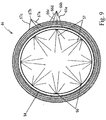
- Fig 1B is an end view of the preferred embodiment from a downstream perspective.
- Fig. 2 is an exploded view of the components in the preferred embodiment of Figs. 1A and 1B .
- the froth generator 1 is generally cylindrical with open ends, namely, inlet end 1a and outlet end 1b.
- the outside diameter (O.D.) of a stainless steel cylinder 2 fits within the inside diameter (I.D.) of a cylindrical stainless steel froth-generator body 3 to provide a means to mechanically support the internal components described below.
- the decontamination or filtering solution is supplied to a spray nozzle 5 through 6.35 mm (0.25 inch) O.D. stainless steel filtering solution distribution tubing 4 that passes through the wall of the cylindrical flange 2 and the wall of the cylindrical froth generator body 3.
- Decontamination solution is distributed through the filtering solution spray nozzle 5 that has eight 1.5875 mm (0.0625 inch) filtering solution spray jets 6 equally spaced around a 6.35 mm (0.25 inch) stainless steel tube 7, 2.54 mm (0.1 inch) from the end of tube 7, concentric with, and at a 10° angle from and perpendicular to, the linear axis of the tube 7, toward the downstream end of tube 7.
- the spray nozzle 5 passes through a 6.35 mm (0.25 inch) hole in the center of a first coarse mesh stainless steel screen 9 and is mechanically fastened to the center of a second coarse mesh stainless steel screen 11, by a stainless steel screw 10 that penetrates the center of the second screen 11.
- the first stainless steel screen 9 is slightly cone-shaped with the top of the cone pointed upstream (to the left in Fig. 2 ).
- the second screen is slightly cone-shaped with the top of the cone pointed downstream (to the right in Fig. 2 ). Both cone-shaped screens 9 and 11 together produce a pocket for the spray nozzle 5 that closes in on itself around the perimeter.
- the spray jets 6 spray out from the center of the screens to evenly saturate coarse mesh stainless-steel screens 9,11 and fine mesh polymeric screens (described below) in three screen or mesh assemblies 12, 14 and 15 downstream of the spray nozzle 5.
- a 25.4 mm (one-inch) wide cylindrical polymeric spacer 8 separates the three screen assemblies 12, 14 and 15 from the mounting flange 2.
- the 6.35 mm (quater-inch) wall thickness of spacer 8 provides structural support for the screen assemblies 12, 14 and 15.
- a contaminated air stream shown by arrows 99 is drawn by relative low pressure through three saturated screen or mesh assemblies 12, 14 and 15, preferably spaced 6.35 mm (0.25 inch) apart.
- the saturated mesh assemblies may be spaced apart other distances, but the preferred spacing is 3.81 to 7.62 mm (0.15 to 0.3 inch).
- the first screen or mesh assembly 12 consists of two conical screens 9 and 11, one fine mesh polymeric screen 17 and one flat coarse mesh stainless steel screen 16. 6.35 mm (quater-inch) cylindrical polymeric spacers 13 separate the screen or mesh assemblies.
- the other two screen or mesh assemblies 14 and 15 each consist of one flat, upstream coarse mesh stainless steel screen 16a, two fine-mesh polymeric screens 17, and one flat, downstream coarse mesh stainless steel screen 16b.
- the coarse mesh stainless steel screens 16 preferably have mesh openings of between 2.54 and 3.81 mm (0.1 and 0.15 inch).
- the polymeric layers have mesh openings preferably between 1.27 and 1.905 mm (0.05 and 0.075 inch).
- the velocity of incoming contaminated air stream as it flows through said mesh openings is greater than 2.54 m/s (500 feet per minute (fpm)) and preferably between 4.064 and 5.08 m/s (800 and 1000 fpm).
- a 12.7 mm (one-half-inch) cylindrical polymeric spacer 18 provides structural support and maintains modest compressive force through the screen assemblies 12, 14 and 15 with the 25.4 mm (one inch) spacer 8 by friction fit in the downstream end of the froth generator body 2.
- Bubbles are continuously produced as the air flows through the wire loops of the mesh assemblies that are saturated with decontamination or filtering solution. Those bubbles burst and reform at each saturated mesh assembly downstream of the first assembly 12. As the bubbles burst, their remnants form numerous super-and-sub-micrometer droplets of decontamination solution in the air stream. As the froth progresses through the saturated mesh matrix, bubbles are reformed, each encapsulating a discrete volume contaminated air, decontamination solution vapor, and decontamination solution micro-droplets. The air velocity relative to the micro-droplets in the air is reduced inside the bubbles. The smallest micro-droplets evaporate, increasing the filtering solution vapor pressure in the air inside the bubbles. Micro-droplets with sufficient mass settle out of the air by the acceleration of gravity. Droplets upon which the buoyant effects of air molecules overcome the acceleration of gravity remain suspended in the air inside the bubbles.
- the froth generator 1 is shown at the inlet end of filter assembly 100.
- the filter assembly 100 removes super-and-sub-micron contaminant aerosols from a contaminated air stream 99. More massive contaminant aerosols entrained in the air stream are carried outside the airflow streamlines by their own momentum and are removed by inertial impaction, as described below. Less massive contaminants are removed downstream by diffusion and contact coalescence, described below.
- the froth generator 1 of the invention is located in inlet plenum 20.
- the outside diameter of the flange 2 ( Fig. 2 ) in the froth generator 1 fits inside an air-inlet duct 19 in the inlet plenum 20, and provides a mechanical connection that joins the froth generator 1(having the saturated mesh panel assemblies 12, 14 and 15) to the air-inlet duct 19, and establishes fluid communication for the introduction of contaminated air stream 99 into the filter 100 through the air inlet duct 19 and sequentially through the froth generator 1.
- the chem/bio filter 100 uses a fluid pump 38 to transfer a chemical-and-biological decontamination (or filtering) solution from the filtering solution reservoir 36 through distribution tubing 37 to froth generator 1 (as shown in Figs. 1A, 1B and 2 ) extending from a 152.4 mm (6 inch) air inlet duct 19 in an inlet plenum 20.
- the froth generator 1 consists of a cylindrical flange 2, a cylindrical froth generator body 3, a filtering solution distribution nozzle 5, three assemblies of four screens each, and a variety of spacers, as described below.
- the present invention is limited to the froth generator 1, with one exception. Most of the filtering methodology and apparatus downstream of the froth generator is prior art, and is described only briefly herein.
- the inlet 19 is caused to enter the inlet 19 as shown by arrows 99 ( Figs. 2 , 3 ) at relatively high velocity.
- the high velocity (more than 2.54 m/s (500 fmp) and preferably 4.064 - 5.08 m/s (800 - 1000 fpm)) is achieved by sizing the cross sectional area of inlet duct (for example, a six inch diameter) much smaller than the cross-sectional area of transition plenum 25, which has more than 2.5 times the cross-sectional area of inlet duct 19.
- the heavy particles, moving at high velocity collide against the serpentine walls of mist eliminator 23 and are easily separated.
- the partially decontaminated air stream reduces its velocity considerably (to about 0.254 m/s (50 fmp)) prior to entering mist eliminators 28 where lighter particles are subsequently filtered as described below.
- Fig. 6 is a simplified schematic representation illustrating the interaction of the contaminated air stream 99 with the three saturated mesh assemblies 12, 14 and 15 shown in Fig. 2 .
- saturated mesh assembly 12 As the contaminated air stream 99 flows along a straight flow path shown by arrows 99 through saturated mesh assembly 12, numerous small bubbles, shown generally as 210, are formed.
- Saturated mesh assembly 12 is kept constantly saturated with filtering solution 200 pumped through nozzle 5.
- the small bubbles 210 burst into numerous fragments or micro-droplets 211. In the preferred embodiment, most bubbles are caused to burst. At least some of the bubbles must be caused to burst to produce the needed micro-droplets.
- a second series of reformed bubbles 220 is generated adjacent to and downstream of assembly 14. Reformed bubbles 220 are caused to burst by the relatively high velocity of contaminated air stream 99, forming numerous micro-droplets 221. Saturated mesh assembly 14 is kept saturated by bubbles 210 and micro-droplets 211.
- Bubbles 220 and micro-droplets 221 contact the third saturated mesh assembly 15, constantly moisten or saturate the assembly 15, and bubbles 220 and micro-droplets 221 are reformed into a third series of small bubbles 230.
- drain line 35 Fig. 3
- Fig. 6 illustrates the case of using 3 saturated mesh assemblies, spaced apart along the flow path of air stream 99, in which the bubbles reform twice.
- the invention applies to the general case of n assemblies wherein the bubbles reform n-1 times.
- a column of filtering solution bubbles (not shown in Fig. 3 for clarity), produced by the froth generator 1, encounters an angled and perforated screening plate 21 that allows a portion of the column of bubbles to go straight and deflects a portion of the bubbles to evenly distribute the aqueous froth over the cross-sectional area of a cold refrigerant coil 22.
- the froth passes over endothermic refrigerant coils, cooling the froth and the air inside the bubbles of the froth, and increasing the filtering solution vapor pressure.
- Decontamination solution initially condenses onto the contaminants in the air inside the bubbles by heterogeneous nucleation. Continued condensation and collision coalescence increases droplet size and mass. A portion of the froth, droplets, and vapor condense onto the cold evaporative coils and drain into the decontamination solution reservoir, as taught in prior art '240 patent.
- Fig. 4 is a top view (in section) of the chem/bio filter 100 of Fig. 3 .
- Closely echeloned, and generally serpentine shaped, angled vanes of a vane-type mist eliminator 23 are positioned adjacent to and downstream of refrigerant coil 22. The froth remaining in the air stream after the cold refrigerant coils 22 is de-watered on vanes of the mist eliminator 23.
- Decontamination solution with trapped contaminants that condenses and collects on the vanes of the mist eliminator 23, drains by way of a drain pan 34 shown in Fig. 3 , through the drain hose 35 back into the decontamination solution reservoir 36.
- the drain pan 34 forms the top of a utility compartment 37 where the filtering solution reservoir 36, filtering solution transfer pumps 38 and 40 and a refrigerant compressor 39 is located, out of the contaminated air stream.
- Super-and-sub-micron-sized decontamination solution droplets a portion of which contain captured contaminants, that remain entrained in the air stream after the vane-type mist eliminator 23, enter a combination mesh mist eliminator 24.
- the combination mesh mist eliminator 24 consists of layers of stainless steel mesh interwoven with fiberglass fibers. The massive micro-droplets remaining in the air stream are removed by inertial impaction and interception on the wires and fibers of the combination mesh mist eliminator 24.
- the decontamination solution micro-droplets, a portion of which contain captured contaminants, that impact onto, or are intercepted by, the wires and fibers of the combination mesh mist eliminator 24 coalesce until the acceleration of gravity causes the filtering solution to drain back into the filtering solution reservoir 36.
- Transition plenum 25 increases in cross-sectional area from the size of the inlet section 42 which forms the first stage of the filter to a size at least 2.5 times larger in the second stage of the filter.
- the air stream with entrained micro-droplets, a portion of which contain captured contaminants, encounters an angled and perforated deflection screen 26 which allows a portion of the air stream to continue straight and deflects a portion of the air stream to the lower half of the transition plenum 25.
- the velocity of the air stream is reduced by more than 50% in the increased cross-sectional area of the transition plenum 25.
- the hot refrigerant coil 27 replaces the heat removed in the cooling or nucleation stage, as described in prior art '240 patent, increasing the Brownian motion of the micro-droplets remaining in the air stream and reducing the relative humidity of the air stream.
- a heat exchanger between the refrigerant condenser coil 27 and the filtering solution reservoir 36 replaces the heat removed from the filtering solution as it passed over the cold refrigerant coil 22.
- the heat exchanger consists of a second fluid transfer pump 40 located next to a refrigerant compressor 88, a stainless steel heat transfer coil 41 located co-lateral to, and immediately downstream of, the refrigerant condenser coil 27, and fluid transfer tubing to circulate the filtering solution through the heat exchanger coil 41 and back to the filtering solution reservoir 36.
- the heat exchanger helps to maintain the thermal gradient between the incoming air stream, the filtering solution, and the cold refrigerant coil 22 that increases heterogeneous nucleation and condensation of decontamination solution vapor onto the contaminants and decontaminant solution micro-droplets in the air stream.
- the air stream enters two cylindrical coalescing fiber mist eliminators 28.
- the air stream enters the outer, cylindrical walls of mist eliminators 28 at a face velocity of preferably less than 10% of inlet velocity, i.e., less than 0.254 m/ s (50fpm). This reduced velocity is achieved since the surface area of mist eliminators 28 (1.068 m 2 ) (11.5 square feet) is more than 20 times the cross-sectional area of inlet duct 19.
- the coalescing fiber mist eliminators 28 consist of 10-micron fibers parallel to each other, wound around a cylindrical perforated metal screen to provide structural support.
- the hydrophobic fibers form cylindrical walls 50.8 mm (two-inches) thick.
- a cylindrical perforated metal screen on the outside of the fibers contains and provides structural support to the hydrophobic fibers.
- Heat-driven collisions between air molecules and filtering solution micro-droplets impart erratic paths (Brownian motion) to the micro-droplets, as the micro-droplets diffuse among the hydrophobic fibers of the mist eliminators 28.
- the air stream passes through the coalescing fiber cylinder walls 29 ( Fig. 4 ) and enters an airflow passageway 30 in the center of the cylindrical mist eliminators 28.
- the micro-droplets contact and coalesce onto the fibers of the mist eliminators 28.
- the decontamination solution micro-droplets, a portion of which contain captured contaminants, that coalesce onto the hydrophobic fibers of the coalescing fiber mist eliminators 28 accumulate until the acceleration of gravity causes the filtering solution to drain to the bottom of the mist eliminators 28.
- the upstream ends of the two cylindrical mist eliminators are sealed with a stainless-steel plate 31.
- the downstream ends of the cylindrical mist eliminators each have a 152.4 mm (6 inch) air-outlet duct 32, which provides fluid communication with an outlet plenum 33.
- the air stream flows out an airflow exhaust duct 39, 152.4 mm (6 inch) in diameter, in the outlet plenum 33.
- Novel features of the chem/bio air filter include a first stage 42 that is characterized by relatively small cross-sectional area in contrast to a second stage 43 characterized by a larger cross-sectional area.
- the small cross-sectional area of the first stage 42 maintains high airflow velocity of more than; 2.54 m/s (500fpm). and preferably 4.064 - 5.08 m/ s (800 - 1000 fpm) to enable inertial impaction of large particles in the beginning of the filtration process.
- the larger cross-sectional area of the second stage 43 is more than 2.5 times the cross-sectional area of first stage 42, and slows the air stream significantly.
- the air stream velocity is further reduced to about 0.254 m/s (50fpm) (less than 10% of inlet velocity) because of the large surface area of mist eliminators 28, as noted above, to enable removal of less massive aerosol contaminants by diffusion and contact coalescence in the end of the filtration process.
- high velocity means more than 2.54 m/s (500fpm)
- low velocity means less than 0.254 m/s (50fpm).
- Fig. 5 illustrates velocity vectors of the air stream when passing through the filter.
- the air stream is initially at relatively high velocity (more than 500 fpm as specified above) in the beginning of the filter to provide the energy required to generate the aqueous froth and force the bubbles through the vanes of the cold refrigerant coil 22.
- the air stream slows slightly in the vane mist eliminator 23 to remove the energy in the air stream to transport the aqueous froth.
- the passageways between the wires and fibers of the combo mesh mist eliminator 23 restrict the air flow and increase the velocity of the air stream.
- the increased velocity of the air stream enables inertial impaction of massive droplets onto the wires and fibers of the mist eliminator 23.
- the air stream encounters the angled screening plate 26 in the transition duct 25 that deflects a portion of the air stream to the bottom of the second stage air duct or plenum 43.
- the velocity of the air stream is reduced in the larger cross-sectional area of the air duct or plenum 43.
- the air stream passes through the hot refrigerant coil 27 and enters the coalescing-fiber mist eliminators 28 at reduced velocity.
- the air stream with entrained micro-droplets, diffuses among the hydrophobic fibers of the mist eliminator 28. At reduced air stream velocity, Brownian motion has greater influence on the paths of the micro-droplets than forward momentum.
- micro-droplets' erratic paths causes the less massive micro-droplets to contact, and coalesce onto the hydrophobic fibers of the mist eliminator 28.
- the acceleration of gravity causes the filtering solution to drain back into the filtering solution reservoir 36.
- Inlet duct 19 152.4 ⁇ mm 6 inch diameter
- Inlet plenum 20 304.8 ⁇ mm ⁇ 431.8 ⁇ mm 12 inch ⁇ 17 inch
- First stage 42 304.8 ⁇ mm ⁇ 431.8 ⁇ mm 12 inch ⁇ 17 inch
- Transition duct 25 304.8 ⁇ mm ⁇ 431.8 ⁇ mm ⁇ 812.8 ⁇ mm 12 inch ⁇ 17 inch ⁇ 32 inch
- Second stage 43 431.8 ⁇ mm ⁇ 812.8 ⁇ mm 17 inch ⁇ 32 inch
- Outlet plenum 33 431.8 ⁇ mm ⁇ 812.8 ⁇ mm 17 inch ⁇ 32 inch
- Outlet duct 39 152.4 ⁇ mm 6 inch diameter
- FIG. 7-9 An alternative embodiment of the froth (and micro-droplet) generator 44 of the invention is shown in Figs. 7-9 in exemplary form as an improved means of generating an aqueous froth and introducing a wide spectrum of filtering solution micro-droplet radii into a contaminated air stream 199 in an industrial air filter 120 to decontaminate air steam 199.
- Air stream 199 may contain toxic industrial chemicals, hazardous bio-active aerosols, acid aerosols formed from sulfur-oxides (SOx), greenhouse gasses from flue-gas from coal-fired industrial boilers, nuisance and corrosive dusts and mists, or valuable recoverable chemicals or metals from an exhaust-gas stream.
- SOx sulfur-oxides
- the froth generator 44 of the invention is illustrated in Figs. 7-9 as a cylindrical extension of contaminated air duct 45 in an industrial wet scrubber.
- a series of four concentric cylindrical screens 66a, 66b, 66c and 66d ( Fig. 9 ) separated by spacers extends from the end of the air duct 45 to the surface of a flowing stream of filtering solution 46a.
- the froth generator and micro-droplet generator 44 is a series of concentric, cylindrical mesh screen assemblies 66a-66d as contrasted with the essentially flat panel assemblies 12, 14 and 15 of Fig. 2 .
- the lowermost end 44a ( Fig. 8 ) of generator 44 extends downwardly into a reservoir 95 of filtering solution.
- the contaminated air stream 199 ( Fig.
- Air stream 199 flows upwardly through scrubber enclosure 50 into exhaust duct 65.
- the saturated mesh assemblies 66a-66d are spaced apart along the horizontal flow path of air stream 199 and each include two coarse mesh, cylindrical stainless steel screens. No polymeric screens are used in this embodiment. Each cylindrical screen has mesh openings between 8.89 mm and 16.51 mm (0.35 inch and 0.65 inch). Air stream velocity through these openings is at least 2.54 m/s (500 fpm) and preferably 4.064 m/s to 5.08 m/s (800 fpm to 1000 fpm).
- a fluid pump 47 pumps filtering solution 46 from a filtering solution settling tank 48 through a filtering solution pipeline 49, to the bottom of a wet-scrubber enclosure 50.
- a second smaller fluid pump 51 pressurizes a distribution pipe network that supplies filtering solution from the filtering solution settling tank 48 to several arrays of spray nozzles.
- the main filtering solution distribution pipe 52 bifurcates between the fluid pump 51 and the wet-scrubber enclosure 50.
- the first distribution pipe 53 continues straight into the wet-scrubber enclosure 50 to supply filtering-solution to the two arrays of spray nozzles 55 in the froth generator 44, the second distribution pipe 87 supplies filtering solution to the four arrays of spray nozzles that limit the froth to a predetermined volume.
- the first distribution pipe 53 supplies two circular filtering solution distribution pipes 54 and 55 collateral to and concentric with, the cylindrical screen walls, and perpendicular to the linear axis of the froth generator 44.
- the first circular filtering solution distribution pipe 54 is located at the top of the froth generator 44 and positioned concentric with, and collateral to the end of the contaminated air duct 45.
- the second circular distribution pipe 55 is located at the interface of the froth generator 44 and the surface of a flowing stream 46a of filtering solution 46, and positioned concentric with, and collateral to, the end of the contaminated air duct 45.
- the circular filtering solution distribution pipes 54 and 55 each have eight filtering-solution spray nozzles 56 ( Fig.
- the contaminated air stream 199 flows through the openings in the saturated mesh panels 66a-66d, separated by spacers 67a-67c forming bubbles that encapsulate a portion of the air stream in each bubble.
- the production of bubbles produces an aqueous froth that encapsulates the contaminated air stream. Bursting bubbles introduce super-and-sub-micrometer droplets into the air stream. Bubbles are reformed three times as the froth progresses through the four saturated mesh assemblies, encapsulating the contaminated air, filtering solution micro-droplets, and filtering solution vapor inside the bubbles of the froth.
- the volume of the froth is limited by a crossed spray 58 of filtering solution droplets across the top of column of froth 59.
- Four circular filtering solution distribution pipes, each having eight filtering solution spray nozzles 56a are positioned to limit of the column of froth 59 to a predetermined volumetric level.
- the two filtering solution distribution pipes 60 and 61 are concentric with, and collateral to, the internal surface of the cylindrical wall of the filter enclosure 50.
- the first filtering solution distribution pipe 60 is approximately 0.5 meters below the second filtering solution distribution pipe 61.
- the spray nozzles 56a of both distribution pipes 60 and 61 are directed inward toward the contaminated air duct 45, at a 10° downward angle, so that the horizontal fan spray pattern of the spray nozzles 56a from the two pipes advance across the top of the column of froth 59 in parallel, providing an initial froth limiting spray of droplets from the array of spray nozzles 56a in the lower pipe 60, and a secondary froth limiting spray of droplets from the array of spray nozzles 56a in the upper filtering solution distribution pipe 61.
- Two additional circular filtering solution distribution pipes 62 and 63 are located concentric with, and collateral to, the outside surface of the contaminated air duct 45, approximately 0.5 meter above the height of the filtering solution distribution pipes 60 and 61 on the internal wall of the filter enclosure 50.
- the filtering solution spray nozzles 56a of the third and fourth filtering solution distribution 62 and 63 pipes spray horizontal fan-shaped patterns of droplets outward, at a 10° downward angle, so that the horizontal fan spray pattern of the spray nozzles from the two pipes advance across the top of the column of froth in parallel, providing an initial froth limiting spray of droplets from the array of spray nozzles 56a in the lower pipe 62, and a secondary froth limiting spray of droplets from the array of spray nozzles in the upper filtering solution distribution pipe 63, from the contaminated air duct 45 towards the internal wall of the filter enclosure 50.
- the air stream with entrained droplets of filtering solution, some of which may contain contaminants, is drawn by low pressure through a centrifugal droplet separator 64. Massive droplets, entrained in the air stream are removed from the air stream, onto the inner wall of the turbine enclosure of the centrifugal separator 64 and drain into the wet-scrubber enclosure 50. The air stream is exhausted from the wet-scrubber 44 through an exhaust-air duct 65.
- Prior art U.S. Patent 6,616,733 teaches using an aqueous froth to remove contaminants from an air stream.
- the aqueous froth is generated by introducing a contaminated air stream into a filtering solution reservoir through a diffusing means below the surface of the liquid.
- the froth expands into a vertical column above the filtering solution reservoir.
- the interface between the contaminated air stream and the filtering solution produces a continuous column of small bubbles that grows at a consistent rate.
- Pressure drop from introducing air stream below the surface of the filtering solution reservoir is relatively high, being directly related to the amount of water that must be displaced to force the air stream through the filtering solution. Large bubbles also formed by the turbulent interface rise through the column of froth at a several times the rate than the smaller bubbles.
- Airflow jet-streams through froth column provide an air duct to quickly transport contaminated air through the column-of-froth with little contact with the filtering solution.
- Prior art U.S. Patent 6,872,240 teaches using heterogeneous nucleation in addition to the aqueous froth to increase the mass and aerodynamic diameter of the contaminants in the air stream.
- An array of fogger nozzles atomize a filtering solution with compressed air to introduce a wide-spectrum of filtering solution droplet-radii into an air stream.
- the air compressor and nozzle array add cost, weight, unnecessary mechanisms that are subject to failure, and unnecessary complexity to the design of the filter.
- the location of the froth generator in the inlet duct, directly upstream of the nucleation stage straightens the airflow streamlines through the filter, reduces the resistance to airflow (pressure drop) across the filter, and increases aerosol removal efficiency and airflow capacity, over the prior art.
- the matrix produced by the saturated closely spaced mesh panels form bubbles of approximately the same size.
- the matrix of mesh panels prevents the formation of large bubbles that carry contaminants through the filter, and increase the liquid-to-gas surface area between the filtering solution and the contaminants in the air stream.
- the matrix also prevents the formation of airflow jet streams through the aqueous froth column, increasing the time of contact between the filtering solution and the contaminants entrained in the air stream.
- Another advantage of the froth generator of the present invention in comparison with the array of fogger nozzles that atomize filtering solution with compressed air to introduce a wide spectrum of filtering solution droplet radii into an air stream, as taught in U.S. Patent 6,872,240 , is the elimination of the air compressor and fogger nozzle array. As the air flows through the openings in the saturated mesh panels, bubbles are formed encapsulating a portion of the air stream in each bubble. Collectively the production of bubbles produces an aqueous froth that encapsulates the contaminated air stream. Bursting bubbles introduce super-and-sub-micrometer droplets into the air stream.
- Bubbles are reformed as the froth progresses through the saturated mesh panels, encapsulating the contaminated air, filtering solution micro-droplets, and filtering solution vapor inside the bubbles of the froth.
- the least massive micro-droplets evaporate, increasing filtering solution vapor pressure in the air inside the bubbles.
- the most massive contaminants or micro-droplets settle out of the air when the acceleration of gravity overcomes the air flow resistance with the surface of the contaminant or micro-droplet.
- Less massive contaminants or micro-droplets, upon which the buoyant effects of air molecules overcome the acceleration of gravity remain suspended in the air, inside the bubbles of the aqueous froth.
- the advantage of the two-stage air duct of the invention is a first stage air duct with high relative airflow velocity resulting from a small cross-sectional area to facilitate the removal of aerosol with enough mass to overcome airflow cushioning near surfaces in a moving air stream by inertial impaction, and a second stage with low relative airflow velocity resulting from a large relative cross-sectional area of the second-stage air duct to facilitate the removal of aerosol from the air stream that do not have enough mass to overcome airflow cushioning by diffusion and contact coalescence.
- the present invention teaches an improved method and provides a means to generate an aqueous froth to remove contaminants from an air stream by forcing the contaminated air stream through a series of saturated mesh panels.
- Filtering solution is pumped from a filtering-solution reservoir to a series of mesh panels positioned perpendicular to the air flow.
- a filtering solution distribution system saturates the mesh panels evenly.
- a contaminated air stream is forced through the saturated mesh panels.
- bubbles are formed encapsulating a portion of the air stream in each bubble.
- Bubbles are reformed as the froth progresses through the saturated mesh panels, encapsulating the contaminated air, filtering solution micro-droplets, and filtering solution vapor inside the bubbles of the froth.
- the least massive micro-droplets evaporate, increasing filtering solution vapor pressure in the air inside the bubbles.
- the most massive contaminants or micro-droplets settle out of the air when the acceleration of gravity overcomes the air flow resistance with the surface of the contaminant or micro-droplet.
- Less massive contaminants or micro-droplets, upon which the buoyant effects of air molecules overcome the acceleration of gravity remain suspended in the air, inside the bubbles of the aqueous froth.
- the invention provides, in exemplary form, a froth generator as an improved means of generating an aqueous froth and introducing a wide spectrum of decontamination solution micro-droplet radii into a contaminated air stream for a high-efficiency sub-micrometer aerosol filtration device to remove, sequester, and kill biological warfare (BW) agent aerosols, and to remove, sequester, and neutralize chemical warfare (CW) agent aerosols and gasses that are captured by the filter, and render non-viable BW or CW agent aerosols that penetrate the filter.
- BW biological warfare
- CW chemical warfare
- the invention also provides, as an alternative example of an improved means of generating an aqueous froth and introducing a wide spectrum of decontamination solution micro-droplet radii into a contaminated air stream, a froth generator for an industrial air filter to decontaminate an air steam containing toxic industrial chemicals or hazardous bio-active aerosols.
- the method of the present invention includes transferring a filtering solution from a filtering-solution reservoir through a distribution means to saturate a series of metallic or polymeric-mesh panels positioned across an air duct.
- a contaminated air stream is forced through the series of saturated mesh panels. Bubbles are continuously produced as the air flows through the wire loops of the mesh panels that are saturated with filtering solution, producing an aqueous froth. A portion of the contaminated air stream is encapsulated inside each bubble of the froth. Bursting bubbles introduce super-and-sub-micrometer droplets of filtering solution into the air stream. As the froth progresses through the saturated-mesh panels, bubbles are reformed encapsulating contaminated air, filtering solution vapor, and filtering solution micro-droplets.
- Airflow velocity is reduced, relative to the contaminants and micro-droplets, in the micro-atmosphere created inside each bubble of the froth.
- the least massive micro-droplets evaporate, increasing the vapor pressure inside the bubbles, enabling heterogeneous nucleation of filtering solution vapor onto the contaminants and micro-droplets in the air, inside the bubbles of the froth.
- the most massive contaminants or micro-droplets settle out of the air when the acceleration of gravity overcomes the airflow resistance with the surface of the aerosols, as taught in U.S. Patent 6,872,240 .
- the aqueous froth is cooled, cooling the micro-atmospheres inside the bubbles of the froth. As the air inside the bubbles cools, heterogeneous nucleation of filtering solution vapor occurs on all the contaminants remaining in the air, inside the bubbles of the froth. Condensation and collision coalescence with other micro-droplets increase the mass and aerodynamic diameter of micro-droplets suspended in the air, as taught in U.S. Patent 6,872,240 .
- the froth that remains in the air stream is de-watered. More massive micro-droplets are removed from the air stream by inertial impaction.
- the air stream with the less massive micro-droplets enters a transition duct that increases in cross-sectional area from the relatively small cross-sectional area of the inlet duct to the larger cross-sectional area of the outlet duct.
- the air stream with entrained micro-droplets is reduced in velocity in the larger cross-sectional area of the outlet duct.
- the air stream is heated, replacing the heat removed during the cooling stage, increasing Brownian motion of the aerosols, and reducing relative humidity of the air stream, as taught in U.S. Patent 6,872,240 .
- a heat exchanger helps to maintain the thermal gradient between the incoming air stream, the filtering solution, and the cooling process that enables heterogeneous nucleation and condensation of filtering solution vapor onto the contaminants and filtering solution micro-droplets in the air stream.
- the decontaminated air stream is exhausted from the filter.
Description
- This invention was first reduced to practice with funding from the Pacific International Center for High Technology Research, Hawaii Technology Development Venture/Office of Naval Research (PICHTR, HTDV/ONR).
- The present invention relates generally to an aqueous froth air filter. More particularly, the present invention provides a significant improvement over my
U.S. patents 6,616,733 and6,872,240 , in the manner of generating the aqueous froth and micro-droplets used to accomplish the filtering of a contaminated air stream.US 4,925,462 describes apparatus for removing organochemical components from a gas.DE 3724099 discloses a gas-foam scrubbing unit.US 3,231,251 discloses a countercurrent gas-liquid contacting column wherein froth is formed from gas bubbling up through porous trays containing liquid. - It has been discovered that the aqueous froth filter systems of my earlier '733 and '240 patents have limited overall filtering efficiency, described in detail below. The '733 patent teaches a system which occasionally generates a froth that includes an excessive percentage of large bubbles in the froth, which detract from the overall filtering performance, as described below. The '240 patent teaches a system wherein micro-droplets are added to the aqueous froth by a series of fogger nozzles. The numerous micro-droplets contribute to the overall effectiveness of the system, but require the use of an air compressor with a fogger nozzle array. The nozzle array is subject to periodic fouling of nozzles and the air compressor is subject to failure, reducing overall filtering efficiency.
- The present invention overcomes the above-described problems with the prior art and, in addition, provides considerably higher overall filtering efficiency. The present invention essentially eliminates the generation of unduly large bubbles (the main weakness of the '733 patent) in part by using a series of saturated mesh panels wherein the mesh openings are small and prevent formation of large bubbles. Large bubbles are also prevented in the present invention by the deliberate bursting of bubbles. The present invention also eliminates the array of fogger nozzles and air compressor required by the '240 patent, while still achieving the generation of micro-droplets which cooperate with the aqueous froth. The present invention generates a much wider micro-droplet diameter and mass distribution than the prior art array of fogger nozzles. Micro-dropfets of different diameter and mass have different momentum in the moving air stream, facilitating collision coalescence between micro-droplets, and removal from the air stream by inertial impaction on the surfaces of the filter. The enormous number of micro-droplets generated by the present invention is achieved by intentionally causing the aqueous froth bubbles to burst and reform between and downstream of each saturated mesh assembly. As the bubbles are intentionally caused to burst, each bursting bubble ruptures into hundreds or thousands of micro-droplets. These micro-droplets are used downstream in the system to coalesce with or to otherwise bind with contaminants in the air stream, and then to remove those contaminants from the air stream.
- The array of saturated mesh assemblies of the present invention generates an aqueous froth having uniformly small bubbles, which enables a high level of filtering efficiency. Simultaneously, the array of saturated mesh assemblies, interacting with the contaminated air stream flowing therethrough, causes bursting and reforming of bubbles preferably two or more times, creating an extremely large number of micro-droplets to interact with contaminants.
- An optional aspect of the invention is to separately filter large particles of contaminant, i.e., particles greater than 3 microns in diameter. These large particles are separated by momentarily increasing the velocity of the contaminated air stream before the air stream encounters the aqueous froth. While the air stream velocity is momentarily increased, these large particles are removed by "inertial impaction," i.e., contact with a high efficiency filter.
- It is significant to note that the present invention is uniquely capable of filtering biological and chemical warfare agents, such as anthrax spores and other deadly agents, from the air stream. Decontamination foams have been developed to kill anthrax spores and many other deadly agents, after those agents have contacted walls and floors and contaminated a building. The present invention acts as a safeguard in the HVAC system to filter out and kill the anthrax spores, for example, prior to contamination of the walls and floors of the building!
- The present invention may also be used as an industrial filter for removing a variety of contaminants in numerous industrial applications.
- A primary object of the invention is to provide a method and apparatus for increasing the overall filtering efficiency of an aqueous froth filter.
- A further object of the invention is to provide an aqueous froth filter which simultaneously generates a froth having relatively uniformly small bubbles and which also generates numerous micro-droplets of different radii, both of which enhance the overall efficiency of the filtering system.
- A further object of the invention is to provide an array of spaced apart saturated mesh assemblies which interact with a contaminated air stream to simultaneously generate a froth having a relatively uniform size of small bubbles and generate numerous micro-droplets of different radii, both of which significantly increase filtering efficiency.
- A further object is to provide a high efficiency aqueous froth filter capable of filtering chemical and biological warfare agents from a contaminated air stream.
- Another object is to provide a high efficiency aqueous froth filter capable of filtering a variety of contaminated, industrially created air streams.
- A further object is to increase overall filtering efficiency of an aqueous froth filter by momentarily increasing the velocity of the contaminated air stream to separately filter large particles by inertial impaction.
- A further object is to increase overall filtering efficiency of an aqueous froth filter by momentarily reducing the velocity of the contaminated air stream to separately filter less massive particles by diffusion.
- Other objects and advantages will become apparent from the following description and drawings, wherein:
-
-
Fig. 1A is a side view of the preferred embodiment of the froth generator; -
Fig. 1B is a section on theline 1B-1B ofFig. 1A ; -
Fig. 2 is an exploded view of the components in the preferred embodiment of the froth generator; -
Fig. 3 is an exploded view, from the side, of the components in the aqueous froth chem/bio aerosol filter; -
Fig. 4 is a top view of the components in the aqueous froth chem/bio aerosol filter ofFig. 3 ; -
Fig. 5 is a side view of velocity vectors through the aqueous froth chem/bio aerosol filter ofFigs. 3 and4 ; -
Fig. 6 is a schematic illustration showing formation of the froth and micro-droplets; -
Fig. 7 is a side view of an industrial air filter incorporating the alternative embodiment of the invention; -
Fig. 8 is a schematic representation of the froth (and micro-droplet) generator portion of the industrial filter ofFig. 7 ; and -
Fig. 9 is a top view on the line 9-9 ofFig. 8 . - In the following description, specific material compositions are representative of the preferred embodiment only, and should not limit the scope of the invention.
- The preferred embodiment of the invention is shown in
Figs. 1A and 1B in exemplary form as an improved means of generating an aqueous froth and introducing a wide-spectrum of filtering or decontamination solution droplet radii into a contaminated air stream for a high-efficiency sub-micrometer aerosol filtration device to remove, sequester, and kill biological warfare (BW) agent aerosols, and to remove, sequester, and neutralize chemical warfare (CW) agent aerosols and gasses.Fig. 1A is a side view, partially in section, of the preferred embodiment of the froth generator (which also generates numerous micro-droplets) shown generally as 1.Fig 1B is an end view of the preferred embodiment from a downstream perspective. -
Fig. 2 is an exploded view of the components in the preferred embodiment ofFigs. 1A and 1B . Thefroth generator 1 is generally cylindrical with open ends, namely, inlet end 1a andoutlet end 1b. The outside diameter (O.D.) of astainless steel cylinder 2 fits within the inside diameter (I.D.) of a cylindrical stainless steel froth-generator body 3 to provide a means to mechanically support the internal components described below. - The decontamination or filtering solution is supplied to a spray nozzle 5 through 6.35 mm (0.25 inch) O.D. stainless steel filtering
solution distribution tubing 4 that passes through the wall of thecylindrical flange 2 and the wall of the cylindricalfroth generator body 3. Decontamination solution is distributed through the filtering solution spray nozzle 5 that has eight 1.5875 mm (0.0625 inch) filteringsolution spray jets 6 equally spaced around a 6.35 mm (0.25 inch)stainless steel tube 7, 2.54 mm (0.1 inch) from the end oftube 7, concentric with, and at a 10° angle from and perpendicular to, the linear axis of thetube 7, toward the downstream end oftube 7. The spray nozzle 5 passes through a 6.35 mm (0.25 inch) hole in the center of a first coarse meshstainless steel screen 9 and is mechanically fastened to the center of a second coarse meshstainless steel screen 11, by astainless steel screw 10 that penetrates the center of thesecond screen 11. The firststainless steel screen 9 is slightly cone-shaped with the top of the cone pointed upstream (to the left inFig. 2 ). The second screen is slightly cone-shaped with the top of the cone pointed downstream (to the right inFig. 2 ). Both cone-shapedscreens spray jets 6 spray out from the center of the screens to evenly saturate coarse mesh stainless-steel screens mesh assemblies - A 25.4 mm (one-inch) wide cylindrical
polymeric spacer 8 separates the threescreen assemblies flange 2. The 6.35 mm (quater-inch) wall thickness ofspacer 8 provides structural support for thescreen assemblies - A contaminated air stream shown by
arrows 99 is drawn by relative low pressure through three saturated screen ormesh assemblies mesh assembly 12 consists of twoconical screens polymeric screen 17 and one flat coarse meshstainless steel screen 16. 6.35 mm (quater-inch)cylindrical polymeric spacers 13 separate the screen or mesh assemblies. The other two screen ormesh assemblies stainless steel screen 16a, two fine-mesh polymeric screens 17, and one flat, downstream coarse meshstainless steel screen 16b. The coarse mesh stainless steel screens 16 preferably have mesh openings of between 2.54 and 3.81 mm (0.1 and 0.15 inch). The polymeric layers have mesh openings preferably between 1.27 and 1.905 mm (0.05 and 0.075 inch). The velocity of incoming contaminated air stream as it flows through said mesh openings is greater than 2.54 m/s (500 feet per minute (fpm)) and preferably between 4.064 and 5.08 m/s (800 and 1000 fpm). - A 12.7 mm (one-half-inch)
cylindrical polymeric spacer 18 provides structural support and maintains modest compressive force through thescreen assemblies spacer 8 by friction fit in the downstream end of thefroth generator body 2. - Bubbles are continuously produced as the air flows through the wire loops of the mesh assemblies that are saturated with decontamination or filtering solution. Those bubbles burst and reform at each saturated mesh assembly downstream of the
first assembly 12. As the bubbles burst, their remnants form numerous super-and-sub-micrometer droplets of decontamination solution in the air stream. As the froth progresses through the saturated mesh matrix, bubbles are reformed, each encapsulating a discrete volume contaminated air, decontamination solution vapor, and decontamination solution micro-droplets. The air velocity relative to the micro-droplets in the air is reduced inside the bubbles. The smallest micro-droplets evaporate, increasing the filtering solution vapor pressure in the air inside the bubbles. Micro-droplets with sufficient mass settle out of the air by the acceleration of gravity. Droplets upon which the buoyant effects of air molecules overcome the acceleration of gravity remain suspended in the air inside the bubbles. - As shown in
Fig. 3 , thefroth generator 1 is shown at the inlet end offilter assembly 100. Thefilter assembly 100 removes super-and-sub-micron contaminant aerosols from a contaminatedair stream 99. More massive contaminant aerosols entrained in the air stream are carried outside the airflow streamlines by their own momentum and are removed by inertial impaction, as described below. Less massive contaminants are removed downstream by diffusion and contact coalescence, described below. - The
froth generator 1 of the invention is located ininlet plenum 20. The outside diameter of the flange 2 (Fig. 2 ) in thefroth generator 1 fits inside an air-inlet duct 19 in theinlet plenum 20, and provides a mechanical connection that joins the froth generator 1(having the saturatedmesh panel assemblies inlet duct 19, and establishes fluid communication for the introduction of contaminatedair stream 99 into thefilter 100 through theair inlet duct 19 and sequentially through thefroth generator 1. - The chem/
bio filter 100 uses afluid pump 38 to transfer a chemical-and-biological decontamination (or filtering) solution from thefiltering solution reservoir 36 throughdistribution tubing 37 to froth generator 1 (as shown inFigs. 1A, 1B and2 ) extending from a 152.4 mm (6 inch)air inlet duct 19 in aninlet plenum 20. Thefroth generator 1 consists of acylindrical flange 2, a cylindricalfroth generator body 3, a filtering solution distribution nozzle 5, three assemblies of four screens each, and a variety of spacers, as described below. - The present invention is limited to the
froth generator 1, with one exception. Most of the filtering methodology and apparatus downstream of the froth generator is prior art, and is described only briefly herein. - One aspect of the present invention that is downstream of
froth generator 1 is the "inertial impaction" aspect of the invention. The "inertial impaction" refers to the filtering of large particles, which is defined as particles greater than 0.3 microns in diameter, by the serpentine shaped vanes ofmist eliminator 23. The contaminatedair stream 99 is caused to enter theinlet 19 as shown by arrows 99 (Figs. 2 ,3 ) at relatively high velocity. The high velocity (more than 2.54 m/s (500 fmp) and preferably 4.064 - 5.08 m/s (800 - 1000 fpm)) is achieved by sizing the cross sectional area of inlet duct (for example, a six inch diameter) much smaller than the cross-sectional area oftransition plenum 25, which has more than 2.5 times the cross-sectional area ofinlet duct 19. The heavy particles, moving at high velocity, collide against the serpentine walls ofmist eliminator 23 and are easily separated. The partially decontaminated air stream reduces its velocity considerably (to about 0.254 m/s (50 fmp)) prior to enteringmist eliminators 28 where lighter particles are subsequently filtered as described below. -
Fig. 6 is a simplified schematic representation illustrating the interaction of the contaminatedair stream 99 with the three saturatedmesh assemblies Fig. 2 . As the contaminatedair stream 99 flows along a straight flow path shown byarrows 99 through saturatedmesh assembly 12, numerous small bubbles, shown generally as 210, are formed.Saturated mesh assembly 12 is kept constantly saturated withfiltering solution 200 pumped through nozzle 5. Thesmall bubbles 210 burst into numerous fragments ormicro-droplets 211. In the preferred embodiment, most bubbles are caused to burst. At least some of the bubbles must be caused to burst to produce the needed micro-droplets. Asbubbles 210 and micro-droplets contact saturatedmesh assembly 14, a second series of reformedbubbles 220 is generated adjacent to and downstream ofassembly 14. Reformed bubbles 220 are caused to burst by the relatively high velocity of contaminatedair stream 99, forming numerous micro-droplets 221.Saturated mesh assembly 14 is kept saturated bybubbles 210 andmicro-droplets 211. -
Bubbles 220 andmicro-droplets 221 contact the third saturatedmesh assembly 15, constantly moisten or saturate theassembly 15, and bubbles 220 andmicro-droplets 221 are reformed into a third series ofsmall bubbles 230. As reformedbubbles 230 move toward cooling orrefrigerant coil 22, some burst to form micro-droplets 231; thebubbles 230 are cooled and are reduced in size to a heavy,dense foam 240. Many of the contaminants have coalesced insidefoam 240 at this stage, and simply drain downwardly through drain line 35 (Fig. 3 ) intotank 36. Asair stream 99 flows through coolingcoil 22, it moves into the second stage of the filtering system, which is not part of the present invention (except for the inertial impaction aspect of the invention). -
Fig. 6 illustrates the case of using 3 saturated mesh assemblies, spaced apart along the flow path ofair stream 99, in which the bubbles reform twice. The invention applies to the general case of n assemblies wherein the bubbles reform n-1 times. - In
Fig. 3 , a column of filtering solution bubbles (not shown inFig. 3 for clarity), produced by thefroth generator 1, encounters an angled andperforated screening plate 21 that allows a portion of the column of bubbles to go straight and deflects a portion of the bubbles to evenly distribute the aqueous froth over the cross-sectional area of a coldrefrigerant coil 22. - The froth passes over endothermic refrigerant coils, cooling the froth and the air inside the bubbles of the froth, and increasing the filtering solution vapor pressure. Decontamination solution initially condenses onto the contaminants in the air inside the bubbles by heterogeneous nucleation. Continued condensation and collision coalescence increases droplet size and mass. A portion of the froth, droplets, and vapor condense onto the cold evaporative coils and drain into the decontamination solution reservoir, as taught in prior art '240 patent.
-
Fig. 4 is a top view (in section) of the chem/bio filter 100 ofFig. 3 . Closely echeloned, and generally serpentine shaped, angled vanes of a vane-type mist eliminator 23 are positioned adjacent to and downstream ofrefrigerant coil 22. The froth remaining in the air stream after the coldrefrigerant coils 22 is de-watered on vanes of themist eliminator 23. Downstream of, and adjacent to, the coldrefrigerant coils 22, cool air flowing between the vanes, and cool fluid draining from the vanes, cool the vanes of themist eliminator 23, increasing the time that heat is removed from the air stream and increasing condensation of decontamination solution vapor onto the contaminants and micro-droplets entrained in the air stream. The most massive micro-droplets entrained in the air stream are removed by inertial impaction on the serpentine shaped vanes of themist eliminator 23 since the massive particles are flowing too fast to follow the serpentine pathway without colliding with one of the vanes. Decontamination solution with trapped contaminants (including large contaminants larger than 0.3 microns in diameter) that condenses and collects on the vanes of themist eliminator 23, drains by way of adrain pan 34 shown inFig. 3 , through thedrain hose 35 back into thedecontamination solution reservoir 36. Thedrain pan 34 forms the top of autility compartment 37 where thefiltering solution reservoir 36, filtering solution transfer pumps 38 and 40 and arefrigerant compressor 39 is located, out of the contaminated air stream. - Super-and-sub-micron-sized decontamination solution droplets, a portion of which contain captured contaminants, that remain entrained in the air stream after the vane-
type mist eliminator 23, enter a combinationmesh mist eliminator 24. The combinationmesh mist eliminator 24 consists of layers of stainless steel mesh interwoven with fiberglass fibers. The massive micro-droplets remaining in the air stream are removed by inertial impaction and interception on the wires and fibers of the combinationmesh mist eliminator 24. The decontamination solution micro-droplets, a portion of which contain captured contaminants, that impact onto, or are intercepted by, the wires and fibers of the combinationmesh mist eliminator 24 coalesce until the acceleration of gravity causes the filtering solution to drain back into thefiltering solution reservoir 36. - As shown in
Fig. 3 , the less massive micro-droplets that remain in the air stream after the combinationmesh mist eliminator 24 enters atransition plenum 25.Transition plenum 25 increases in cross-sectional area from the size of theinlet section 42 which forms the first stage of the filter to a size at least 2.5 times larger in the second stage of the filter. The air stream with entrained micro-droplets, a portion of which contain captured contaminants, encounters an angled andperforated deflection screen 26 which allows a portion of the air stream to continue straight and deflects a portion of the air stream to the lower half of thetransition plenum 25. The velocity of the air stream is reduced by more than 50% in the increased cross-sectional area of thetransition plenum 25. - The air stream, at reduced velocity with entrained micro-droplets, a portion of which contain captured contaminants, pass through an exothermic
refrigerant coil 27. The hotrefrigerant coil 27 replaces the heat removed in the cooling or nucleation stage, as described in prior art '240 patent, increasing the Brownian motion of the micro-droplets remaining in the air stream and reducing the relative humidity of the air stream. - A heat exchanger between the
refrigerant condenser coil 27 and thefiltering solution reservoir 36 replaces the heat removed from the filtering solution as it passed over the coldrefrigerant coil 22. The heat exchanger consists of a secondfluid transfer pump 40 located next to a refrigerant compressor 88, a stainless steelheat transfer coil 41 located co-lateral to, and immediately downstream of, therefrigerant condenser coil 27, and fluid transfer tubing to circulate the filtering solution through theheat exchanger coil 41 and back to thefiltering solution reservoir 36. The heat exchanger helps to maintain the thermal gradient between the incoming air stream, the filtering solution, and the coldrefrigerant coil 22 that increases heterogeneous nucleation and condensation of decontamination solution vapor onto the contaminants and decontaminant solution micro-droplets in the air stream. - The air stream, at reduced velocity of less than 0.254 m/s (50fpm) and increased Brownian motion with entrained micro-droplets, a portion of which contain captured contaminants, enter two cylindrical coalescing
fiber mist eliminators 28. The air stream enters the outer, cylindrical walls ofmist eliminators 28 at a face velocity of preferably less than 10% of inlet velocity, i.e., less than 0.254 m/ s (50fpm). This reduced velocity is achieved since the surface area of mist eliminators 28 (1.068 m2) (11.5 square feet) is more than 20 times the cross-sectional area ofinlet duct 19. The coalescingfiber mist eliminators 28 consist of 10-micron fibers parallel to each other, wound around a cylindrical perforated metal screen to provide structural support. The hydrophobic fibers form cylindrical walls 50.8 mm (two-inches) thick. A cylindrical perforated metal screen on the outside of the fibers contains and provides structural support to the hydrophobic fibers. Heat-driven collisions between air molecules and filtering solution micro-droplets impart erratic paths (Brownian motion) to the micro-droplets, as the micro-droplets diffuse among the hydrophobic fibers of themist eliminators 28. The air stream passes through the coalescing fiber cylinder walls 29 (Fig. 4 ) and enters anairflow passageway 30 in the center of thecylindrical mist eliminators 28. The micro-droplets contact and coalesce onto the fibers of themist eliminators 28. The decontamination solution micro-droplets, a portion of which contain captured contaminants, that coalesce onto the hydrophobic fibers of the coalescingfiber mist eliminators 28 accumulate until the acceleration of gravity causes the filtering solution to drain to the bottom of themist eliminators 28. The upstream ends of the two cylindrical mist eliminators are sealed with a stainless-steel plate 31. The downstream ends of the cylindrical mist eliminators each have a 152.4 mm (6 inch) air-outlet duct 32, which provides fluid communication with anoutlet plenum 33. The air stream flows out anairflow exhaust duct 39, 152.4 mm (6 inch) in diameter, in theoutlet plenum 33. - Novel features of the chem/bio air filter, illustrated in
Fig. 3 , include afirst stage 42 that is characterized by relatively small cross-sectional area in contrast to asecond stage 43 characterized by a larger cross-sectional area. The small cross-sectional area of thefirst stage 42 maintains high airflow velocity of more than; 2.54 m/s (500fpm). and preferably 4.064 - 5.08 m/ s (800 - 1000 fpm) to enable inertial impaction of large particles in the beginning of the filtration process. The larger cross-sectional area of thesecond stage 43 is more than 2.5 times the cross-sectional area offirst stage 42, and slows the air stream significantly. The air stream velocity is further reduced to about 0.254 m/s (50fpm) (less than 10% of inlet velocity) because of the large surface area ofmist eliminators 28, as noted above, to enable removal of less massive aerosol contaminants by diffusion and contact coalescence in the end of the filtration process. As used herein and in the claims, the phrase "high velocity" means more than 2.54 m/s (500fpm), and the phrase "low velocity" means less than 0.254 m/s (50fpm). -
Fig. 5 illustrates velocity vectors of the air stream when passing through the filter. The air stream is initially at relatively high velocity (more than 500 fpm as specified above) in the beginning of the filter to provide the energy required to generate the aqueous froth and force the bubbles through the vanes of the coldrefrigerant coil 22. The air stream slows slightly in thevane mist eliminator 23 to remove the energy in the air stream to transport the aqueous froth. The passageways between the wires and fibers of the combomesh mist eliminator 23 restrict the air flow and increase the velocity of the air stream. The increased velocity of the air stream enables inertial impaction of massive droplets onto the wires and fibers of themist eliminator 23. The air stream encounters the angledscreening plate 26 in thetransition duct 25 that deflects a portion of the air stream to the bottom of the second stage air duct orplenum 43. The velocity of the air stream is reduced in the larger cross-sectional area of the air duct orplenum 43. The air stream passes through the hotrefrigerant coil 27 and enters the coalescing-fiber mist eliminators 28 at reduced velocity. The air stream, with entrained micro-droplets, diffuses among the hydrophobic fibers of themist eliminator 28. At reduced air stream velocity, Brownian motion has greater influence on the paths of the micro-droplets than forward momentum. The micro-droplets' erratic paths causes the less massive micro-droplets to contact, and coalesce onto the hydrophobic fibers of themist eliminator 28. When the micro-droplets accumulate enough mass, the acceleration of gravity causes the filtering solution to drain back into thefiltering solution reservoir 36. - Listed below are dimensions of the preferred embodiment shown in
Fig. 3 :


- An alternative embodiment of the froth (and micro-droplet)
generator 44 of the invention is shown inFigs. 7-9 in exemplary form as an improved means of generating an aqueous froth and introducing a wide spectrum of filtering solution micro-droplet radii into a contaminatedair stream 199 in anindustrial air filter 120 to decontaminateair steam 199.Air stream 199 may contain toxic industrial chemicals, hazardous bio-active aerosols, acid aerosols formed from sulfur-oxides (SOx), greenhouse gasses from flue-gas from coal-fired industrial boilers, nuisance and corrosive dusts and mists, or valuable recoverable chemicals or metals from an exhaust-gas stream. - The
froth generator 44 of the invention is illustrated inFigs. 7-9 as a cylindrical extension of contaminatedair duct 45 in an industrial wet scrubber. A series of four concentriccylindrical screens Fig. 9 ) separated by spacers extends from the end of theair duct 45 to the surface of a flowing stream offiltering solution 46a. The froth generator andmicro-droplet generator 44 is a series of concentric, cylindricalmesh screen assemblies 66a-66d as contrasted with the essentiallyflat panel assemblies Fig. 2 . Thelowermost end 44a (Fig. 8 ) ofgenerator 44 extends downwardly into areservoir 95 of filtering solution. The contaminated air stream 199 (Fig. 8 ) exitsair duct 45 and either flows along a horizontal flow path through saturatedmesh assemblies 66a-66d or along a downward and radially outward flow path throughfiltering solution 46 inreservoir 95.Air stream 199 flows upwardly throughscrubber enclosure 50 intoexhaust duct 65. - The saturated
mesh assemblies 66a-66d are spaced apart along the horizontal flow path ofair stream 199 and each include two coarse mesh, cylindrical stainless steel screens. No polymeric screens are used in this embodiment. Each cylindrical screen has mesh openings between 8.89 mm and 16.51 mm (0.35 inch and 0.65 inch). Air stream velocity through these openings is at least 2.54 m/s (500 fpm) and preferably 4.064 m/s to 5.08 m/s (800 fpm to 1000 fpm). - A
fluid pump 47pumps filtering solution 46 from a filteringsolution settling tank 48 through afiltering solution pipeline 49, to the bottom of a wet-scrubber enclosure 50. A secondsmaller fluid pump 51 pressurizes a distribution pipe network that supplies filtering solution from the filteringsolution settling tank 48 to several arrays of spray nozzles. The main filteringsolution distribution pipe 52 bifurcates between thefluid pump 51 and the wet-scrubber enclosure 50. Thefirst distribution pipe 53 continues straight into the wet-scrubber enclosure 50 to supply filtering-solution to the two arrays ofspray nozzles 55 in thefroth generator 44, thesecond distribution pipe 87 supplies filtering solution to the four arrays of spray nozzles that limit the froth to a predetermined volume. - The
first distribution pipe 53 supplies two circular filteringsolution distribution pipes froth generator 44. The first circular filteringsolution distribution pipe 54 is located at the top of thefroth generator 44 and positioned concentric with, and collateral to the end of the contaminatedair duct 45. The secondcircular distribution pipe 55 is located at the interface of thefroth generator 44 and the surface of a flowingstream 46a offiltering solution 46, and positioned concentric with, and collateral to, the end of the contaminatedair duct 45. The circular filteringsolution distribution pipes Fig. 9 ) positioned to spray a cone-shapedpattern 57 of filtering solution droplets across the air stream (only two droplet patterns are illustrated from eachdistribution pipe spray nozzle 56. The filteringsolution spray nozzles 56 in thedistribution pipe 54 near the top of thefroth generator 44 spray at a downward angle onto the internal wall on the opposite side of thefroth generator 44. The spray nozzles 56 in thedistribution pipe 55 at the bottom of thefroth generator 44 spray at an upward angle onto the internal wall on the oppositeside froth generator 44. - The contaminated
air stream 199 flows through the openings in the saturatedmesh panels 66a-66d, separated byspacers 67a-67c forming bubbles that encapsulate a portion of the air stream in each bubble. Collectively the production of bubbles produces an aqueous froth that encapsulates the contaminated air stream. Bursting bubbles introduce super-and-sub-micrometer droplets into the air stream. Bubbles are reformed three times as the froth progresses through the four saturated mesh assemblies, encapsulating the contaminated air, filtering solution micro-droplets, and filtering solution vapor inside the bubbles of the froth. - The volume of the froth is limited by a crossed
spray 58 of filtering solution droplets across the top of column offroth 59. Four circular filtering solution distribution pipes, each having eight filteringsolution spray nozzles 56a are positioned to limit of the column offroth 59 to a predetermined volumetric level. The two filteringsolution distribution pipes filter enclosure 50. The first filteringsolution distribution pipe 60 is approximately 0.5 meters below the second filteringsolution distribution pipe 61. Thespray nozzles 56a of bothdistribution pipes air duct 45, at a 10° downward angle, so that the horizontal fan spray pattern of thespray nozzles 56a from the two pipes advance across the top of the column offroth 59 in parallel, providing an initial froth limiting spray of droplets from the array ofspray nozzles 56a in thelower pipe 60, and a secondary froth limiting spray of droplets from the array ofspray nozzles 56a in the upper filteringsolution distribution pipe 61. Two additional circular filteringsolution distribution pipes air duct 45, approximately 0.5 meter above the height of the filteringsolution distribution pipes filter enclosure 50. The filteringsolution spray nozzles 56a of the third and fourthfiltering solution distribution spray nozzles 56a in thelower pipe 62, and a secondary froth limiting spray of droplets from the array of spray nozzles in the upper filteringsolution distribution pipe 63, from the contaminatedair duct 45 towards the internal wall of thefilter enclosure 50. The spray ofdroplets 58 from the four arrays of spray nozzles, in concert, limit the volume of froth to the predetermined level. The air stream with entrained droplets of filtering solution, some of which may contain contaminants, is drawn by low pressure through acentrifugal droplet separator 64. Massive droplets, entrained in the air stream are removed from the air stream, onto the inner wall of the turbine enclosure of thecentrifugal separator 64 and drain into the wet-scrubber enclosure 50. The air stream is exhausted from the wet-scrubber 44 through an exhaust-air duct 65. - Prior art
U.S. Patent 6,616,733 teaches using an aqueous froth to remove contaminants from an air stream. The aqueous froth is generated by introducing a contaminated air stream into a filtering solution reservoir through a diffusing means below the surface of the liquid. The froth expands into a vertical column above the filtering solution reservoir. The interface between the contaminated air stream and the filtering solution produces a continuous column of small bubbles that grows at a consistent rate. Pressure drop from introducing air stream below the surface of the filtering solution reservoir is relatively high, being directly related to the amount of water that must be displaced to force the air stream through the filtering solution. Large bubbles also formed by the turbulent interface rise through the column of froth at a several times the rate than the smaller bubbles. Large bubbles have less liquid-to-gas surface area than small bubbles and the faster rate-of-climb through column-of-froth reduce the time-of-contact between the contaminants in the air stream and the filtering solution. Airflow jet-streams through froth column provide an air duct to quickly transport contaminated air through the column-of-froth with little contact with the filtering solution. - Prior art
U.S. Patent 6,872,240 teaches using heterogeneous nucleation in addition to the aqueous froth to increase the mass and aerodynamic diameter of the contaminants in the air stream. An array of fogger nozzles atomize a filtering solution with compressed air to introduce a wide-spectrum of filtering solution droplet-radii into an air stream. The air compressor and nozzle array add cost, weight, unnecessary mechanisms that are subject to failure, and unnecessary complexity to the design of the filter. - The advantages to generating an aqueous froth with the froth generator of the present invention, in comparison with introducing the contaminated air stream beneath the surface of the filtering solution reservoir, as taught in
U.S. Patent 6,616,733 , are numerous. The location of the froth generator in the inlet duct, directly upstream of the nucleation stage straightens the airflow streamlines through the filter, reduces the resistance to airflow (pressure drop) across the filter, and increases aerosol removal efficiency and airflow capacity, over the prior art. The matrix produced by the saturated closely spaced mesh panels form bubbles of approximately the same size. The matrix of mesh panels prevents the formation of large bubbles that carry contaminants through the filter, and increase the liquid-to-gas surface area between the filtering solution and the contaminants in the air stream. The matrix also prevents the formation of airflow jet streams through the aqueous froth column, increasing the time of contact between the filtering solution and the contaminants entrained in the air stream. - Another advantage of the froth generator of the present invention, in comparison with the array of fogger nozzles that atomize filtering solution with compressed air to introduce a wide spectrum of filtering solution droplet radii into an air stream, as taught in
U.S. Patent 6,872,240 , is the elimination of the air compressor and fogger nozzle array. As the air flows through the openings in the saturated mesh panels, bubbles are formed encapsulating a portion of the air stream in each bubble. Collectively the production of bubbles produces an aqueous froth that encapsulates the contaminated air stream. Bursting bubbles introduce super-and-sub-micrometer droplets into the air stream. Bubbles are reformed as the froth progresses through the saturated mesh panels, encapsulating the contaminated air, filtering solution micro-droplets, and filtering solution vapor inside the bubbles of the froth. The least massive micro-droplets evaporate, increasing filtering solution vapor pressure in the air inside the bubbles. The most massive contaminants or micro-droplets settle out of the air when the acceleration of gravity overcomes the air flow resistance with the surface of the contaminant or micro-droplet. Less massive contaminants or micro-droplets, upon which the buoyant effects of air molecules overcome the acceleration of gravity, remain suspended in the air, inside the bubbles of the aqueous froth. - The advantage of the two-stage air duct of the invention is a first stage air duct with high relative airflow velocity resulting from a small cross-sectional area to facilitate the removal of aerosol with enough mass to overcome airflow cushioning near surfaces in a moving air stream by inertial impaction, and a second stage with low relative airflow velocity resulting from a large relative cross-sectional area of the second-stage air duct to facilitate the removal of aerosol from the air stream that do not have enough mass to overcome airflow cushioning by diffusion and contact coalescence.
- The present invention teaches an improved method and provides a means to generate an aqueous froth to remove contaminants from an air stream by forcing the contaminated air stream through a series of saturated mesh panels. Filtering solution is pumped from a filtering-solution reservoir to a series of mesh panels positioned perpendicular to the air flow. A filtering solution distribution system saturates the mesh panels evenly. A contaminated air stream is forced through the saturated mesh panels. As the air flows through the openings in the saturated mesh panels, bubbles are formed encapsulating a portion of the air stream in each bubble. Collectively the production of bubbles produces an aqueous froth that encapsulates the contaminated air stream. Bursting bubbles introduce super-and-sub-micrometer droplets into the air stream. Bubbles are reformed as the froth progresses through the saturated mesh panels, encapsulating the contaminated air, filtering solution micro-droplets, and filtering solution vapor inside the bubbles of the froth. The least massive micro-droplets evaporate, increasing filtering solution vapor pressure in the air inside the bubbles. The most massive contaminants or micro-droplets settle out of the air when the acceleration of gravity overcomes the air flow resistance with the surface of the contaminant or micro-droplet. Less massive contaminants or micro-droplets, upon which the buoyant effects of air molecules overcome the acceleration of gravity, remain suspended in the air, inside the bubbles of the aqueous froth. The invention provides, in exemplary form, a froth generator as an improved means of generating an aqueous froth and introducing a wide spectrum of decontamination solution micro-droplet radii into a contaminated air stream for a high-efficiency sub-micrometer aerosol filtration device to remove, sequester, and kill biological warfare (BW) agent aerosols, and to remove, sequester, and neutralize chemical warfare (CW) agent aerosols and gasses that are captured by the filter, and render non-viable BW or CW agent aerosols that penetrate the filter. The invention also provides, as an alternative example of an improved means of generating an aqueous froth and introducing a wide spectrum of decontamination solution micro-droplet radii into a contaminated air stream, a froth generator for an industrial air filter to decontaminate an air steam containing toxic industrial chemicals or hazardous bio-active aerosols.
- The method of the present invention includes transferring a filtering solution from a filtering-solution reservoir through a distribution means to saturate a series of metallic or polymeric-mesh panels positioned across an air duct. A contaminated air stream is forced through the series of saturated mesh panels. Bubbles are continuously produced as the air flows through the wire loops of the mesh panels that are saturated with filtering solution, producing an aqueous froth. A portion of the contaminated air stream is encapsulated inside each bubble of the froth. Bursting bubbles introduce super-and-sub-micrometer droplets of filtering solution into the air stream. As the froth progresses through the saturated-mesh panels, bubbles are reformed encapsulating contaminated air, filtering solution vapor, and filtering solution micro-droplets.
- Airflow velocity is reduced, relative to the contaminants and micro-droplets, in the micro-atmosphere created inside each bubble of the froth. The least massive micro-droplets evaporate, increasing the vapor pressure inside the bubbles, enabling heterogeneous nucleation of filtering solution vapor onto the contaminants and micro-droplets in the air, inside the bubbles of the froth. Less massive micro-droplets, upon which the buoyant effects of air molecules overcome the acceleration of gravity, remain suspended in the air inside the bubbles. The most massive contaminants or micro-droplets settle out of the air when the acceleration of gravity overcomes the airflow resistance with the surface of the aerosols, as taught in
U.S. Patent 6,872,240 . - The aqueous froth is cooled, cooling the micro-atmospheres inside the bubbles of the froth. As the air inside the bubbles cools, heterogeneous nucleation of filtering solution vapor occurs on all the contaminants remaining in the air, inside the bubbles of the froth. Condensation and collision coalescence with other micro-droplets increase the mass and aerodynamic diameter of micro-droplets suspended in the air, as taught in
U.S. Patent 6,872,240 . - The froth that remains in the air stream is de-watered. More massive micro-droplets are removed from the air stream by inertial impaction. The air stream with the less massive micro-droplets enters a transition duct that increases in cross-sectional area from the relatively small cross-sectional area of the inlet duct to the larger cross-sectional area of the outlet duct. The air stream with entrained micro-droplets is reduced in velocity in the larger cross-sectional area of the outlet duct.
- The air stream is heated, replacing the heat removed during the cooling stage, increasing Brownian motion of the aerosols, and reducing relative humidity of the air stream, as taught in
U.S. Patent 6,872,240 . - A heat exchanger helps to maintain the thermal gradient between the incoming air stream, the filtering solution, and the cooling process that enables heterogeneous nucleation and condensation of filtering solution vapor onto the contaminants and filtering solution micro-droplets in the air stream.
- Less-massive micro-droplets are removed from the air stream by diffusion and contact coalescence.
- The decontaminated air stream is exhausted from the filter.
- The foregoing description of the invention has been presented for the purposes of illustration and description and is not intended to be exhaustive or limit the invention to the precise form disclosed. The embodiments were chosen and described to best explain the principles of the invention and its practical application to thereby enable others skilled in the art to best use the invention in various embodiments and other various modifications suited to the particular use contemplated. The scope of the invention is to be defined by the following claims.
Claims (13)
- A method of generating an aqueous froth from an aqueous filtering solution simultaneously with numerous micro-droplets from said aqueous filtering solution, said micro-droplets having various radii for use in an aqueous froth filtering system which removes contaminants from a contaminated air stream moving along a flow path, comprising the steps:providing a plurality of n mesh assemblies, said mesh assemblies being spaced apart along said flow path of said contaminated air stream,saturating said plurality of mesh assemblies with aqueous filtering solution which forms aqueous froth when air is passed through a mesh assembly saturated with the aqueous filtering solution,passing said contaminated air stream through said plurality of mesh assemblies, thereby forming an aqueous froth having a large array of bubbles downstream of each of said saturated mesh assemblies as said contaminated air stream flows through each assembly,progressing aqueous froth through saturated mesh assemblies downstream of the first assembly, andcausing at least some of said bubbles to burst and reform n-1 times as said contaminated air stream and said aqueous froth pass through said saturated mesh assemblies downstream of the first assembly, said bursting bubbles forming said numerous micro-droplets having various radii, wherein each reforming bubble encapsulates a discrete volume of said contaminated air stream, a discrete number of said filtering solution microdroplets, and a discrete volume of filtering solution vapor,characterised in that each of said saturated mesh assemblies comprises first and second stainless steel mesh layers and first and second polymeric layers located between said first and second stainless steel mesh layers.
- The method of claim 1 comprising the further step of creating a relatively high velocity of said contaminated air stream in a first stage to remove large particles by inertial impaction.
- The method of claim 1 comprising the further step of creating a relatively low velocity air stream in a second stage to remove particles by diffusion and contact coalescence.
- The method of claim 1, wherein each of said stainless steel mesh layers have mesh openings of between 2.45 mm and 3.81 mm, said each of said polymeric layers have mesh openings of between 1.27 mm and 1.905 mm, and wherein said contaminated air stream flows through said openings at more than 2.54.
- The method of claim 1 wherein each of saturated mesh assemblies comprises first and second cylindrical, stainless steel mesh layers.
- Apparatus for generating an aqueous froth simultaneously with numerous micro-droplets having various radii, for use in an aqueous froth filtering system for removing contaminants from a contaminated air stream moving along a flow path, comprising:a plurality of n mesh assemblies, said mesh assemblies being spaced apart along said flow path of said contaminated air stream,means for saturating said plurality of n mesh assemblies with an aqueous filtering solution,means for passing said contaminated air stream through said plurality of saturated mesh assemblies, for forming an aqueous froth having a large array of bubbles adjacent to and downstream of each saturated mesh assembly, and for progressing aqueous froth through saturated mesh assemblies downstream of the first assemblycharacterised in that each of said mesh assemblies comprises first and second stainless steel mesh layers and first and second polymeric layers located between said first and second stainless steel mesh layers, so as to cause at least some of said bubbles to burst and reform n -1 times as said contaminated air stream and said aqueous froth pass through said saturated mesh assemblies downstream of the first assembly, whereby said bursting bubbles form said numerous micro-droplets having various radii, and wherein each reforming bubble encapsulates a discrete volume of said contaminated air stream, a discrete number of said micro-droplets, and a discrete volume of filtering solution vapor.
- The apparatus of claim 6 further comprising means for creating relative high air stream velocity in a primary stage to remove more massive particles by inertial impaction.
- The apparatus of claim 7 further comprising means for creating relative low air stream velocity in a secondary stage to remove less massive particles by diffusion and contact coalescence.
- The apparatus of claim 6 wherein n = 3.
- The apparatus of claim 9 wherein each of said stainless steel mesh layers have mesh openings of between 2.45 mm and 3.81 mm, said each of said polymeric layers have mesh openings of between 1.27 mm and 1.905 mm and wherein said contaminated air stream flows through said openings at more than 2.54 m/s.
- The apparatus of claim 10 wherein n = 3 and each of said assemblies is spaced apart a distance of between 3.81 mm an 7.62 mm.
- The apparatus of claim 6 wherein each of said mesh assemblies comprises first and second cylindrical, stainless steel mesh layers.
- The apparatus of claim 12 wherein each of said cylindrical, stainless steel mesh layers have mesh openings between 8.89 mm and 16.51 mm, and said air stream flows through said openings at between 4.064 m/s and 5.08 m/s.
Applications Claiming Priority (2)
| Application Number | Priority Date | Filing Date | Title |
|---|---|---|---|
| US78659306P | 2006-03-28 | 2006-03-28 | |
| PCT/US2007/007763 WO2008005080A2 (en) | 2006-03-28 | 2007-03-28 | Method and means for simultaneously generating and aqueous froth and numerous micro-droplets for use in filtering a contaminated air stream |
Publications (4)
| Publication Number | Publication Date |
|---|---|
| EP1998868A2 EP1998868A2 (en) | 2008-12-10 |
| EP1998868A4 EP1998868A4 (en) | 2014-08-13 |
| EP1998868B1 true EP1998868B1 (en) | 2020-01-01 |
| EP1998868B8 EP1998868B8 (en) | 2020-03-04 |
Family
ID=38895052
Family Applications (1)
| Application Number | Title | Priority Date | Filing Date |
|---|---|---|---|
| EP07835717.5A Active EP1998868B8 (en) | 2006-03-28 | 2007-03-28 | Method and means for simultaneously generating an aqueous froth and numerous micro-droplets for use in filtering a contaminated air stream |
Country Status (3)
| Country | Link |
|---|---|
| US (1) | US7854791B2 (en) |
| EP (1) | EP1998868B8 (en) |
| WO (1) | WO2008005080A2 (en) |
Families Citing this family (12)
| Publication number | Priority date | Publication date | Assignee | Title |
|---|---|---|---|---|
| SE0900131A1 (en) * | 2009-02-04 | 2010-08-05 | Bengt Eggemar | Air Cleaning |
| JP2014508037A (en) * | 2011-02-14 | 2014-04-03 | ウェステック エンバイロメンタル ソルーションズ エルエルシー | Absorber |
| CN102198359B (en) * | 2011-06-09 | 2013-07-31 | 北京绿创环保设备股份有限公司 | Coating waste gas treatment equipment |
| US10646819B2 (en) * | 2012-02-13 | 2020-05-12 | Industrial Climate Solutions, Inc. | Absorber |
| US9545598B2 (en) * | 2012-02-13 | 2017-01-17 | Westec Environmental Solutions, Llc | Absorber |
| FR3014548B1 (en) * | 2013-12-11 | 2018-11-30 | Starklab | PROVIDING THE PRODUCTION OF AN AIR FLOW WHOSE TEMPERATURE IS CONTROLLED BY THERMAL EXCHANGE WITH A LIQUID AND WITH DIRECT CONTACT OF THE AIR FLOW AND THE FLUID |
| MA40912A (en) * | 2014-11-06 | 2017-09-12 | Starklab | DEVICE FOR THE PRODUCTION AND TREATMENT OF A GAS FLOW THROUGH A VOLUME OF LIQUID, INSTALLATION AND PROCESS IMPLEMENTING THIS DEVICE |
| CN107713755A (en) * | 2017-11-16 | 2018-02-23 | 江门市乐米电器有限公司 | A kind of electric heating products brokenly bubble component |
| JP7397085B2 (en) | 2019-01-23 | 2023-12-12 | ブルー プラネット システムズ コーポレーション | Carbonate aggregate compositions and methods for their manufacture and use |
| KR20220056021A (en) * | 2020-10-27 | 2022-05-04 | 삼성전자주식회사 | particulate matter collector |
| CN113426237A (en) * | 2021-07-06 | 2021-09-24 | 桂林金山新材料有限公司 | Carbon dioxide treatment equipment and treatment method for calcium carbonate production |
| CN114917625B (en) * | 2022-05-20 | 2023-05-30 | 佛山德众制药机械有限公司 | Device for automatically removing liquid level fine foam |
Citations (2)
| Publication number | Priority date | Publication date | Assignee | Title |
|---|---|---|---|---|
| US3811247A (en) * | 1971-10-20 | 1974-05-21 | G Huppke | Foam type gas scrubber |
| WO2007021670A2 (en) * | 2005-08-09 | 2007-02-22 | Kemal Burkay | Polluted air treatment method and system |
Family Cites Families (18)
| Publication number | Priority date | Publication date | Assignee | Title |
|---|---|---|---|---|
| US2172710A (en) * | 1939-09-12 | Air cleaner for vacuum brakes | ||
| US996991A (en) * | 1909-06-11 | 1911-07-04 | Cleaning Devices Mfg Company | Vacuum apparatus. |
| US972183A (en) * | 1910-01-20 | 1910-10-11 | Carl Guntrum | Air-filter. |
| US1838645A (en) * | 1929-01-07 | 1931-12-29 | Albert P J Voigt | Muffler |
| US1810394A (en) * | 1929-02-21 | 1931-06-16 | Schaumbad Gmbh | Means for the production of foam |
| US1860111A (en) * | 1929-05-04 | 1932-05-24 | Arthur W Miller | Air cleaner |
| US1994766A (en) * | 1934-06-25 | 1935-03-19 | George L Heglar | Air cleaner and washer |
| US2069889A (en) * | 1934-12-17 | 1937-02-09 | Donaldson Co Inc | Air cleaner |
| US2207689A (en) * | 1937-07-23 | 1940-07-09 | J E Baker | Gas plant |
| US2466162A (en) * | 1946-07-03 | 1949-04-05 | Cedar Corp N O | Display and demonstration apparatus |
| US2575400A (en) * | 1947-05-26 | 1951-11-20 | William C Shirk | Crankcase breather and oil filler pipe assembly |
| US3231251A (en) * | 1962-05-10 | 1966-01-25 | York Process Equipment Corp | Froth disengagement in gas-liquid contact apparatus |
| US4140635A (en) * | 1977-04-13 | 1979-02-20 | Esmond William G | Purification device |
| DE3707576A1 (en) * | 1987-03-10 | 1988-09-22 | Arasin Gmbh | METHOD AND DEVICE FOR SEPARATING ORGANIC CHEMICAL INGREDIENTS |
| DE3724099A1 (en) * | 1987-07-21 | 1988-04-21 | Geier Henninger Kurt | Gas-foam scrubber |
| EP1259306A1 (en) * | 1999-10-07 | 2002-11-27 | Peletex, Inc. | Method and means for filtering an air stream with an aqueous froth |
| US6872240B2 (en) * | 2001-07-10 | 2005-03-29 | Peletex, Inc. | Method and apparatus for filtering an air stream using an aqueous-froth together with nucleation |
| US6966942B2 (en) * | 2002-02-22 | 2005-11-22 | Broadbent Alan Hyrum | Process for purifying exhaust gases by employing a bubble generator |
-
2007
- 2007-03-28 WO PCT/US2007/007763 patent/WO2008005080A2/en active Application Filing
- 2007-03-28 US US11/729,253 patent/US7854791B2/en active Active
- 2007-03-28 EP EP07835717.5A patent/EP1998868B8/en active Active
Patent Citations (3)
| Publication number | Priority date | Publication date | Assignee | Title |
|---|---|---|---|---|
| US3811247A (en) * | 1971-10-20 | 1974-05-21 | G Huppke | Foam type gas scrubber |
| WO2007021670A2 (en) * | 2005-08-09 | 2007-02-22 | Kemal Burkay | Polluted air treatment method and system |
| EP1984095A2 (en) * | 2005-08-09 | 2008-10-29 | Kemal Burkay | Polluted air treatment method and system |
Also Published As
| Publication number | Publication date |
|---|---|
| WO2008005080A2 (en) | 2008-01-10 |
| EP1998868A2 (en) | 2008-12-10 |
| EP1998868B8 (en) | 2020-03-04 |
| EP1998868A4 (en) | 2014-08-13 |
| US20080017032A1 (en) | 2008-01-24 |
| US7854791B2 (en) | 2010-12-21 |
| WO2008005080A3 (en) | 2008-03-27 |
Similar Documents
| Publication | Publication Date | Title |
|---|---|---|
| EP1998868B1 (en) | Method and means for simultaneously generating an aqueous froth and numerous micro-droplets for use in filtering a contaminated air stream | |
| US6872240B2 (en) | Method and apparatus for filtering an air stream using an aqueous-froth together with nucleation | |
| US4437867A (en) | Removal of undesired components from gases | |
| US7811343B2 (en) | Method and apparatus for separating liquid droplets from a gas stream | |
| US9005340B2 (en) | Fiber bed assembly including a re-entrainment control device for a fiber bed mist eliminator | |
| CA2446171C (en) | Flue gas desulfurization system with a stepped tray | |
| KR101478973B1 (en) | Scrubber for removing acidic gases using multi gas-liquid contact device | |
| US8968450B1 (en) | Wet scrubber design | |
| EP2675548B1 (en) | Method of absorbing a gas compound | |
| WO2015024014A1 (en) | Co2 capture system and method | |
| JPH0741139B2 (en) | Method and apparatus for multi-ejector type gas cleaning | |
| CA2259828C (en) | Packing grates for wet gas scrubber and other applications | |
| JPH04344495A (en) | Reactor container decompression device | |
| CA1106777A (en) | Removal of undesired components from gases | |
| US4153432A (en) | Apparatus and method for collection of contaminants | |
| KR200425748Y1 (en) | Water layer generating structure of impinjet scrubber | |
| EP1545745B1 (en) | Method and apparatus for filtering an air stream using an aqueous-froth together with nucleation | |
| KR101072480B1 (en) | Wet type scrubber | |
| RU2097111C1 (en) | Gas-treatment apparatus | |
| CN214513547U (en) | Vertical oil-gas separation device | |
| CN108837656B (en) | Composite micron-sized aerosol treatment device | |
| CN214513254U (en) | Horizontal oil-gas separation device | |
| US8562709B2 (en) | Low density mist collector pad | |
| JPH0659361B2 (en) | Fluid treatment equipment | |
| JP6923193B2 (en) | Dehumidifier |
Legal Events
| Date | Code | Title | Description |
|---|---|---|---|
| PUAI | Public reference made under article 153(3) epc to a published international application that has entered the european phase |
Free format text: ORIGINAL CODE: 0009012 |
|
| 17P | Request for examination filed |
Effective date: 20080929 |
|
| AK | Designated contracting states |
Kind code of ref document: A2 Designated state(s): AT BE BG CH CY CZ DE DK EE ES FI FR GB GR HU IE IS IT LI LT LU LV MC MT NL PL PT RO SE SI SK TR |
|
| RAP1 | Party data changed (applicant data changed or rights of an application transferred) |
Owner name: WESTEC ENVIRONMENTAL SOLUTIONS, LLC |
|
| DAX | Request for extension of the european patent (deleted) | ||
| A4 | Supplementary search report drawn up and despatched |
Effective date: 20140715 |
|
| RIC1 | Information provided on ipc code assigned before grant |
Ipc: B01D 47/04 20060101AFI20140709BHEP Ipc: B01F 3/04 20060101ALI20140709BHEP |
|
| 17Q | First examination report despatched |
Effective date: 20160322 |
|
| STAA | Information on the status of an ep patent application or granted ep patent |
Free format text: STATUS: EXAMINATION IS IN PROGRESS |
|
| GRAP | Despatch of communication of intention to grant a patent |
Free format text: ORIGINAL CODE: EPIDOSNIGR1 |
|
| STAA | Information on the status of an ep patent application or granted ep patent |
Free format text: STATUS: GRANT OF PATENT IS INTENDED |
|
| INTG | Intention to grant announced |
Effective date: 20190108 |
|
| INTG | Intention to grant announced |
Effective date: 20190108 |
|
| GRAJ | Information related to disapproval of communication of intention to grant by the applicant or resumption of examination proceedings by the epo deleted |
Free format text: ORIGINAL CODE: EPIDOSDIGR1 |
|
| STAA | Information on the status of an ep patent application or granted ep patent |
Free format text: STATUS: EXAMINATION IS IN PROGRESS |
|
| INTC | Intention to grant announced (deleted) | ||
| GRAP | Despatch of communication of intention to grant a patent |
Free format text: ORIGINAL CODE: EPIDOSNIGR1 |
|
| STAA | Information on the status of an ep patent application or granted ep patent |
Free format text: STATUS: GRANT OF PATENT IS INTENDED |
|
| INTG | Intention to grant announced |
Effective date: 20190712 |
|
| GRAS | Grant fee paid |
Free format text: ORIGINAL CODE: EPIDOSNIGR3 |
|
| GRAA | (expected) grant |
Free format text: ORIGINAL CODE: 0009210 |
|
| STAA | Information on the status of an ep patent application or granted ep patent |
Free format text: STATUS: THE PATENT HAS BEEN GRANTED |
|
| AK | Designated contracting states |
Kind code of ref document: B1 Designated state(s): AT BE BG CH CY CZ DE DK EE ES FI FR GB GR HU IE IS IT LI LT LU LV MC MT NL PL PT RO SE SI SK TR |
|
| REG | Reference to a national code |
Ref country code: GB Ref legal event code: FG4D |
|
| REG | Reference to a national code |
Ref country code: CH Ref legal event code: EP Ref country code: AT Ref legal event code: REF Ref document number: 1219060 Country of ref document: AT Kind code of ref document: T Effective date: 20200115 |
|
| RAP2 | Party data changed (patent owner data changed or rights of a patent transferred) |
Owner name: INDUSTRIAL CLIMATE SOLUTIONS, INC. |
|
| REG | Reference to a national code |
Ref country code: IE Ref legal event code: FG4D |
|
| REG | Reference to a national code |
Ref country code: DE Ref legal event code: R096 Ref document number: 602007059697 Country of ref document: DE |
|
| REG | Reference to a national code |
Ref country code: CH Ref legal event code: PK Free format text: BERICHTIGUNG B8 |
|
| PGFP | Annual fee paid to national office [announced via postgrant information from national office to epo] |
Ref country code: GB Payment date: 20200312 Year of fee payment: 14 |
|
| REG | Reference to a national code |
Ref country code: NL Ref legal event code: MP Effective date: 20200101 |
|
| PGFP | Annual fee paid to national office [announced via postgrant information from national office to epo] |
Ref country code: FR Payment date: 20200326 Year of fee payment: 14 |
|
| REG | Reference to a national code |
Ref country code: LT Ref legal event code: MG4D |
|
| PG25 | Lapsed in a contracting state [announced via postgrant information from national office to epo] |
Ref country code: PT Free format text: LAPSE BECAUSE OF FAILURE TO SUBMIT A TRANSLATION OF THE DESCRIPTION OR TO PAY THE FEE WITHIN THE PRESCRIBED TIME-LIMIT Effective date: 20200527 Ref country code: NL Free format text: LAPSE BECAUSE OF FAILURE TO SUBMIT A TRANSLATION OF THE DESCRIPTION OR TO PAY THE FEE WITHIN THE PRESCRIBED TIME-LIMIT Effective date: 20200101 Ref country code: LT Free format text: LAPSE BECAUSE OF FAILURE TO SUBMIT A TRANSLATION OF THE DESCRIPTION OR TO PAY THE FEE WITHIN THE PRESCRIBED TIME-LIMIT Effective date: 20200101 Ref country code: FI Free format text: LAPSE BECAUSE OF FAILURE TO SUBMIT A TRANSLATION OF THE DESCRIPTION OR TO PAY THE FEE WITHIN THE PRESCRIBED TIME-LIMIT Effective date: 20200101 |
|
| PGFP | Annual fee paid to national office [announced via postgrant information from national office to epo] |
Ref country code: DE Payment date: 20200326 Year of fee payment: 14 |
|
| PG25 | Lapsed in a contracting state [announced via postgrant information from national office to epo] |
Ref country code: IS Free format text: LAPSE BECAUSE OF FAILURE TO SUBMIT A TRANSLATION OF THE DESCRIPTION OR TO PAY THE FEE WITHIN THE PRESCRIBED TIME-LIMIT Effective date: 20200501 Ref country code: GR Free format text: LAPSE BECAUSE OF FAILURE TO SUBMIT A TRANSLATION OF THE DESCRIPTION OR TO PAY THE FEE WITHIN THE PRESCRIBED TIME-LIMIT Effective date: 20200402 Ref country code: SE Free format text: LAPSE BECAUSE OF FAILURE TO SUBMIT A TRANSLATION OF THE DESCRIPTION OR TO PAY THE FEE WITHIN THE PRESCRIBED TIME-LIMIT Effective date: 20200101 Ref country code: LV Free format text: LAPSE BECAUSE OF FAILURE TO SUBMIT A TRANSLATION OF THE DESCRIPTION OR TO PAY THE FEE WITHIN THE PRESCRIBED TIME-LIMIT Effective date: 20200101 Ref country code: BG Free format text: LAPSE BECAUSE OF FAILURE TO SUBMIT A TRANSLATION OF THE DESCRIPTION OR TO PAY THE FEE WITHIN THE PRESCRIBED TIME-LIMIT Effective date: 20200401 |
|
| REG | Reference to a national code |
Ref country code: DE Ref legal event code: R097 Ref document number: 602007059697 Country of ref document: DE |
|
| PG25 | Lapsed in a contracting state [announced via postgrant information from national office to epo] |
Ref country code: EE Free format text: LAPSE BECAUSE OF FAILURE TO SUBMIT A TRANSLATION OF THE DESCRIPTION OR TO PAY THE FEE WITHIN THE PRESCRIBED TIME-LIMIT Effective date: 20200101 Ref country code: DK Free format text: LAPSE BECAUSE OF FAILURE TO SUBMIT A TRANSLATION OF THE DESCRIPTION OR TO PAY THE FEE WITHIN THE PRESCRIBED TIME-LIMIT Effective date: 20200101 Ref country code: ES Free format text: LAPSE BECAUSE OF FAILURE TO SUBMIT A TRANSLATION OF THE DESCRIPTION OR TO PAY THE FEE WITHIN THE PRESCRIBED TIME-LIMIT Effective date: 20200101 Ref country code: RO Free format text: LAPSE BECAUSE OF FAILURE TO SUBMIT A TRANSLATION OF THE DESCRIPTION OR TO PAY THE FEE WITHIN THE PRESCRIBED TIME-LIMIT Effective date: 20200101 Ref country code: CZ Free format text: LAPSE BECAUSE OF FAILURE TO SUBMIT A TRANSLATION OF THE DESCRIPTION OR TO PAY THE FEE WITHIN THE PRESCRIBED TIME-LIMIT Effective date: 20200101 Ref country code: MC Free format text: LAPSE BECAUSE OF FAILURE TO SUBMIT A TRANSLATION OF THE DESCRIPTION OR TO PAY THE FEE WITHIN THE PRESCRIBED TIME-LIMIT Effective date: 20200101 Ref country code: SK Free format text: LAPSE BECAUSE OF FAILURE TO SUBMIT A TRANSLATION OF THE DESCRIPTION OR TO PAY THE FEE WITHIN THE PRESCRIBED TIME-LIMIT Effective date: 20200101 |
|
| REG | Reference to a national code |
Ref country code: CH Ref legal event code: PL |
|
| PLBE | No opposition filed within time limit |
Free format text: ORIGINAL CODE: 0009261 |
|
| STAA | Information on the status of an ep patent application or granted ep patent |
Free format text: STATUS: NO OPPOSITION FILED WITHIN TIME LIMIT |
|
| REG | Reference to a national code |
Ref country code: AT Ref legal event code: MK05 Ref document number: 1219060 Country of ref document: AT Kind code of ref document: T Effective date: 20200101 |
|
| 26N | No opposition filed |
Effective date: 20201002 |
|
| REG | Reference to a national code |
Ref country code: BE Ref legal event code: MM Effective date: 20200331 |
|
| PG25 | Lapsed in a contracting state [announced via postgrant information from national office to epo] |
Ref country code: LU Free format text: LAPSE BECAUSE OF NON-PAYMENT OF DUE FEES Effective date: 20200328 |
|
| PG25 | Lapsed in a contracting state [announced via postgrant information from national office to epo] |
Ref country code: IE Free format text: LAPSE BECAUSE OF NON-PAYMENT OF DUE FEES Effective date: 20200328 Ref country code: IT Free format text: LAPSE BECAUSE OF FAILURE TO SUBMIT A TRANSLATION OF THE DESCRIPTION OR TO PAY THE FEE WITHIN THE PRESCRIBED TIME-LIMIT Effective date: 20200101 Ref country code: LI Free format text: LAPSE BECAUSE OF NON-PAYMENT OF DUE FEES Effective date: 20200331 Ref country code: CH Free format text: LAPSE BECAUSE OF NON-PAYMENT OF DUE FEES Effective date: 20200331 Ref country code: AT Free format text: LAPSE BECAUSE OF FAILURE TO SUBMIT A TRANSLATION OF THE DESCRIPTION OR TO PAY THE FEE WITHIN THE PRESCRIBED TIME-LIMIT Effective date: 20200101 |
|
| PG25 | Lapsed in a contracting state [announced via postgrant information from national office to epo] |
Ref country code: BE Free format text: LAPSE BECAUSE OF NON-PAYMENT OF DUE FEES Effective date: 20200331 Ref country code: PL Free format text: LAPSE BECAUSE OF FAILURE TO SUBMIT A TRANSLATION OF THE DESCRIPTION OR TO PAY THE FEE WITHIN THE PRESCRIBED TIME-LIMIT Effective date: 20200101 Ref country code: SI Free format text: LAPSE BECAUSE OF FAILURE TO SUBMIT A TRANSLATION OF THE DESCRIPTION OR TO PAY THE FEE WITHIN THE PRESCRIBED TIME-LIMIT Effective date: 20200101 |
|
| REG | Reference to a national code |
Ref country code: DE Ref legal event code: R119 Ref document number: 602007059697 Country of ref document: DE |
|
| GBPC | Gb: european patent ceased through non-payment of renewal fee |
Effective date: 20210328 |
|
| PG25 | Lapsed in a contracting state [announced via postgrant information from national office to epo] |
Ref country code: FR Free format text: LAPSE BECAUSE OF NON-PAYMENT OF DUE FEES Effective date: 20210331 Ref country code: GB Free format text: LAPSE BECAUSE OF NON-PAYMENT OF DUE FEES Effective date: 20210328 Ref country code: DE Free format text: LAPSE BECAUSE OF NON-PAYMENT OF DUE FEES Effective date: 20211001 |
|
| PG25 | Lapsed in a contracting state [announced via postgrant information from national office to epo] |
Ref country code: TR Free format text: LAPSE BECAUSE OF FAILURE TO SUBMIT A TRANSLATION OF THE DESCRIPTION OR TO PAY THE FEE WITHIN THE PRESCRIBED TIME-LIMIT Effective date: 20200101 Ref country code: MT Free format text: LAPSE BECAUSE OF FAILURE TO SUBMIT A TRANSLATION OF THE DESCRIPTION OR TO PAY THE FEE WITHIN THE PRESCRIBED TIME-LIMIT Effective date: 20200101 Ref country code: CY Free format text: LAPSE BECAUSE OF FAILURE TO SUBMIT A TRANSLATION OF THE DESCRIPTION OR TO PAY THE FEE WITHIN THE PRESCRIBED TIME-LIMIT Effective date: 20200101 |