EP1998690B1 - A method for manufacturing a nerve regeneration device - Google Patents
A method for manufacturing a nerve regeneration device Download PDFInfo
- Publication number
- EP1998690B1 EP1998690B1 EP07748342.8A EP07748342A EP1998690B1 EP 1998690 B1 EP1998690 B1 EP 1998690B1 EP 07748342 A EP07748342 A EP 07748342A EP 1998690 B1 EP1998690 B1 EP 1998690B1
- Authority
- EP
- European Patent Office
- Prior art keywords
- mould
- nerve
- nerve regeneration
- spinal cord
- nerves
- Prior art date
- Legal status (The legal status is an assumption and is not a legal conclusion. Google has not performed a legal analysis and makes no representation as to the accuracy of the status listed.)
- Active
Links
Images



Classifications
-
- A—HUMAN NECESSITIES
- A61—MEDICAL OR VETERINARY SCIENCE; HYGIENE
- A61B—DIAGNOSIS; SURGERY; IDENTIFICATION
- A61B17/00—Surgical instruments, devices or methods
- A61B17/11—Surgical instruments, devices or methods for performing anastomosis; Buttons for anastomosis
- A61B17/1128—Surgical instruments, devices or methods for performing anastomosis; Buttons for anastomosis of nerves
-
- A—HUMAN NECESSITIES
- A61—MEDICAL OR VETERINARY SCIENCE; HYGIENE
- A61P—SPECIFIC THERAPEUTIC ACTIVITY OF CHEMICAL COMPOUNDS OR MEDICINAL PREPARATIONS
- A61P25/00—Drugs for disorders of the nervous system
-
- B—PERFORMING OPERATIONS; TRANSPORTING
- B28—WORKING CEMENT, CLAY, OR STONE
- B28B—SHAPING CLAY OR OTHER CERAMIC COMPOSITIONS; SHAPING SLAG; SHAPING MIXTURES CONTAINING CEMENTITIOUS MATERIAL, e.g. PLASTER
- B28B7/00—Moulds; Cores; Mandrels
- B28B7/16—Moulds for making shaped articles with cavities or holes open to the surface, e.g. with blind holes
- B28B7/18—Moulds for making shaped articles with cavities or holes open to the surface, e.g. with blind holes the holes passing completely through the article
-
- A—HUMAN NECESSITIES
- A61—MEDICAL OR VETERINARY SCIENCE; HYGIENE
- A61B—DIAGNOSIS; SURGERY; IDENTIFICATION
- A61B17/00—Surgical instruments, devices or methods
- A61B2017/00526—Methods of manufacturing
Definitions
- the present invention uses a mould by which a device for nerve regeneration in the spinal cord can be manufactured. Said device can be used to treat a spinal cord injury.
- the invention is a method of manufacturing such a device.
- the central nervous system In contrast to the peripheral nervous system, the central nervous system (CNS) is unable to heal when injured. At present an injury to the spinal cord in humans leads to permanent paralysis below the place of the injury.
- BDNF Brain-derived neurotrophic factor
- GDNF glial-derived neurotrophic factor
- aFGF acidic fibroblast neurotrophic factor
- the nerve paths of a healthy person run in the white matter of the spinal cord. It is known that injured axons in the CNS will grow into grafts of peripheral nerves. Attempts have been made to bridge the injured area by using several peripheral nerve grafts to extend the central axons to the caudal part of the spinal cord. Such methods are based on the idea that the white matter of the spinal cord comprises the inhibiting factors, whereas the grey substance is more permissive to regrowth. At present, therefore the peripheral nerve grafts may be arranged so that the newly grown axons will direct signals from the white matter to the grey matter of the spinal cord, as a strategy to circumvent the inhibitory environment for nerve regeneration in the white matter. Detailed knowledge is available about the location of the white and grey matter, respectively, in the human spinal cord, and about the positions of the axons.
- WO98/04197 proposes the use of a device having a substantially cylindrical form and containing holes or channels for bridging openings in the proximal end with openings in the distal end.
- the channels may be filled with peripheral nerves taken from the patient.
- the peripheral nerves will grow together with the central axons of the spinal cord, thus interconnecting the proximal and the distal end of the injured area.
- a problem associated with connecting white matter to grey matter is that the connections will not follow straight lines.
- the nerve regeneration device must be made in such a way that these nerve grafts do not intercept each other and that they are positioned exactly where they should be anatomically in order to restore function to the greatest degree possible.
- WO 98/04197 briefly proposes the use of flexible tubes around which the biocompatible material is moulded, to achieve the desired channels.
- US 6,214,021 B1 discloses a method of manufacturing a nerve regeneration device comprising providing a mould comprising a bottom plate, a top plate and a centre part, each of said plates having a number of holes, and said centre part having a bore therethrough, placing wires in the bore, each exiting the mould through one hole in the top plate and a hole in the bottom plate, filling the mould with a material to produce the device, removing the device from the mould and removing the wires from the device.
- DE 103 09 237 A1 discloses a method of manufacturing a nerve regeneration device in which a spinal cord injury is imaged, and a natural sponge grown or shaped on the basis of the image data forms the nerve regeneration device, in which the sponge's breathing canals constitute open channels.
- a method of manufacturing a nerve regeneration device for treating a spinal cord injury of a patient comprising the following steps:
- the following step may be performed, together or at separate points in time:
- a mould for manufacturing a device for treating a spinal cord injury of a patient comprising a base plate, a top plate and a centre part, each of said base plate and said top plate having a number of holes corresponding to points in the injured spinal cord where nerves should be regenerated, and said centre part having a channel therethrough, arranged to receive a number of threads, each thread exiting the mould through one hole in the top plate and a matching hole in the base plate.
- the method comprises the preparatory steps of imaging the spinal cord injury using an imaging technique, obtaining image data related to the shape and size of the injury and providing the mould having a shape and size matching the spinal cord injury on the basis of said image data.
- the imaging technique may be a radiological imaging technique, such as computer tomography (CT) or magnetic resonance imaging (MRI) or any other imaging technique used in the treatment of patients.
- the biocompatible material or biodegradable material may comprise an agent to stimulate nerve regeneration. This agent will then be distributed gradually to the regenerating nerves in order to stimulate growth.
- each of the first structures is placed through holes in the top plates situated to correspond to grey matter area and holes in the base plates situated to correspond to white matter area, and vice versa. This is feasible because nerve regeneration is more readily achieved in grey matter than in white matter.
- the step of inserting nerves in the channels may comprise the steps of inserting second threads in the channels, fastening a nerve to each of the second threads and pulling each nerve into the channel by means of said second threads.
- Said second threads are preferably substantially thinner than the first flexible structures. It may be possible to use the first flexible structures to pull nerve grafts into the channels.
- the step of inserting nerves and/or biological material promoting nerve regeneration in the channels comprises the step of pulling or pushing nerve grafts into the channels.
- the peripheral nerves are preferably taken from another part of the patient's body.
- the flexible elongate structures preferably have a cross-sectional dimension corresponding to the thickness of a nerve, so that the channels produced will also have a cross-sectional dimension corresponding to the thickness of a nerve.
- Also disclosed are a set of moulds comprising a number of moulds according to the above. In this way a number of prefabricated moulds can be provided and the one that best matches an individual injury to be treated can be selected to produce the nerve regeneration device for this particular injury.
- the nerve regeneration device may be made in any material that is biocompatible.
- a dental cement is proposed.
- the use of a biodegradable material such as fibrin (Tisel product) or modifications of this product with higher concentration of fibrinogen clotting to fibrin giving a more compact structure is useful.
- a biodegradable material is advantageous, since this will disappear in vivo, leaving only the regenerated axons. It will also provide a vehicle for sustained release of factors stimulating nerve regeneration.
- the nerve regeneration device may contain one or more of the following: nerve regeneration promoting factors such as aFGF, NFG, other growth factors, chABC and/or antibodies that will neutralize the action of nerve growth inhibiting components in the spinal cord and nerve roots.
- the material may be precharged with a growth factor, or a combination of growth factors, such as aFGF or chABC, and/or antibodies.
- a growth factor or a combination of growth factors, such as aFGF or chABC, and/or antibodies.
- Antibodies will neutralize the action of components in the spinal cord and roots that inhibit nerve regeneration.
- the growth factor and/or antibodies will then be gradually transferred from the nerve regeneration device to the nerve grafts, thus stimulating nerve regeneration over a period of time.
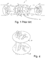
- Figure 1 shows a nerve regeneration device 2 known in the art for use in the treatment of spinal cord injuries device.
- the nerve regeneration device 2 has the form of a cylinder with a proximal end area 5 and a distal end area 6, each end area having first 8 and second 9 parts.
- the first parts 8 and the second parts 9 of the proximal and distal ends 5, 6 respectively, are white and shaded, respectively.
- the device contains channels 4, of which three are shown in the drawing. One channel 4 leads from the first part 8 of the proximal end area 5 to the second part 9 of the distal area 6. Another channel leads from the second part 9 of the proximal end area 5 to the first part 8 of the distal end area 6.
- One of the channels 4 ends in an opening 7 on the side area 14 of the device in order to be shunted past the distal end of the injury and introduced into the spinal cord further down at a suitable angle through the white into the grey matter.
- the channels have been threaded with peripheral nerve grafts (not shown).
- peripheral nerve grafts In the device of Figure 1 descending motor pathways from proximal white were coupled to distal grey matter and ascending pathways from distal white to proximal grey matter, according to the arrows.
- peripheral nerve grafts a biological material that promotes nerve regeneration may be inserted into the channels.
- Such biological material can be produced in vitro from stem cells or cells that are found around nerve fibres such as, for example, neurons, Schwann cells, macrophages such as microglia, and fibroblasts.
- Other examples of biological material that can be used in this context include extracellular matrix component structures, such as collagene-like structures, elastine, glucosaminoglucanes or other connective tissue substances. This applies throughout this document where nerve grafts are inserted into, or present in, the channels.
- Figure 1 shows a nerve regeneration device for bridging a gap across the whole cross section of the spinal cord.
- the nerve regeneration device may be adapted to any shape and size of the injury covering a partial or full cross section of the spinal cord as well as any level of the spinal cord, all levels with unique dimensions,
- the end areas may be plane or have any other desired shape to match the end areas of the injury.
- FIG. 2 is a flow chart of the inventive method for producing the nerve regeneration device according to the invention. As will be obvious to the skilled person, some steps could change order, and/or be performed jointly, for example step S24 might be performed before step S23, or after step S25.
- step S21 the damaged area of the spinal cord is reproduced using a radiological imaging technique common in the art, to produce image data relating to the size and shape of the damaged area and the cross-section of the spinal cord at the position of the damage.
- imaging techniques include computer tomography, nuclear magnetic resonance and others, any of which may be used in the context of the present invention.
- step S22 the data obtained in step S21 are used to determine the shape and size of the nerve regeneration device that should be produced to bridge the proximal and distal ends of the injured area.
- step S23 the positions of the entry holes of each channel at each end of the nerve regeneration device are determined.
- step S24 the different parts of the mould in which the nerve regeneration device should be made are formed using any suitable method known in the art, such as turning or milling.
- the edges at both ends of the side walls may be even, or may have any suitable shape to match the injury.
- the proximal and distal end walls are formed, having essentially the same shape as the cross-section of the side walls.
- the end walls may be plane or may have a suitable shape to match the edges of the side walls.
- step S25 holes are provided in the end walls, where entry points should be present for the nerves that are to form the connections between the proximal and distal ends. The positioning of the holes is discussed below, in connection with Fig. 3 .
- step S26 the mould is partly assembled, for example, as discussed in connection with Figure 6 , to allow threads to be placed in the mould between the entry points.
- step S27 threads, wires or other flexible elongate structures having a suitable cross-sectional dimension are placed between the entry points so that channels will be formed where the threads are running.
- the structures used are referred to as threads in this description.
- the threads may be nylon threads, for example, fishing line of a suitable dimension.
- step S28 the mould is filled with a suitable biocompatible or biodegradable material in which the nerve regeneration device is to be made. Suitable materials are discussed above. As stated above, the material may also be treated or mixed in various ways with growth factors or antibodies to promote regeneration of the nerves. The nerve regeneration device is then allowed to polymerize or solidify until it is dry.
- step S29 the threads are removed from the mould, resulting in open channels through the nerve regeneration device, which, when placed in the injured area, will connect the proximal and the distal ends in the desired points.
- step S30 the channels are filled with peripheral nerves taken from another part of the patient's body. This may be done by inserting a thin thread, much thinner than the thread used in step S27 to form the channels, through each channel, fastening the thin thread to a nerve, for example by tying them together, and pulling the nerve through the channel.
- the nerve grafts may be sucked into the channels by means of a suction technique or inserted by a pushing technique involving pressurized gas or any other suitable method.
- a preloaded flexible tube comprising the nerve grafts may be pushed into the channel.
- step S31 when all the channels in the nerve regeneration device have been filled with nerve grafts, the nerve regeneration device is ready to be placed in the injured part of the spinal cord.
- the mould can be made to create a larger device, which can then be shaped by cutting, milling or another suitable process to the desired size and shape.
- a device corresponding to the entire cross-section of the spinal cord can be made and the part of the device corresponding to the part of the spinal cord that is intact can be removed.
- the steps related to imaging, determining the shape and size, and forming the mould are preferably performed by an imaging system as discussed above connected to a CAD/CAM system (Computer Aided Design/Computer Aided Manufacturing).
- CAD/CAM system Computer Aided Design/Computer Aided Manufacturing
- the threads used in step S27, as well as the holes in the top and bottom plates preferably have approximately the same dimensions as the nerves that are to be inserted in the channels.
- Figure 3 illustrates how matching holes in the proximal and distal end plates can be positioned.
- Figure 3 is prepared for rats, but similar topographical maps can be prepared for human beings.
- the same proximal and distal end plates of a mould are shown in a number of pairs 3a - 31 of map.
- the left part of the map shows the proximal end plate and the right part of the map shows the distal end plate.
- a dent is provided in the one end plate to enable filling the mould and for marking the direction.
- One pair of matching holes is marked in black for each pair of maps That is, the holes marked as black in the left and right part of the pair 3a are one pair of matching holes, between which a thread should be provided, to form a channel.
- the end plates do not have to be elliptic, but can be part of a circle of ellipse as well.
- the actual position of the holes will depend on the position of the nerve paths that are to be regenerated, which in turn depends on the position of the injury in the spinal cord.
- FIG. 3 12 holes are shown, which has been found to be suitable in rats.
- the number of holes is restricted by the cross-sectional area and the shape of the device.
- a greater number of holes will be feasible, for example 18 or 24 or an even greater number of holes.
- the greater the number of holes the more nerve paths can be regenerated, which will probably produce a better result.
- the holes must be placed in a way that is suitable for regenerating nerve paths in a human spinal cord. Maps of the human spinal cord can be found in a number of medical textbooks, for example, The human nervous system (2004) Paxinos & Mai, Academic Press Inc .
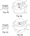
- Figure 4 illustrates the proximal and distal end plates, or top 27 and bottom 37 plates, of a mould, with threads provided between some of the entry holes. For clarity, the side wall is not shown. As can be seen, the threads extend in curved lines to provide connections from white to grey matter.
- Figure 5 illustrates a mould arranged in a holder 21 according to an embodiment of the invention.
- the mould is made of a suitable metal, but it may, of course, have any suitable design and be made from any other suitable material as well, such as plastic.
- the holder 1 may be shaped in any suitable way and is mounted on a base 23.
- the mould comprises a base plate 25, and a top plate 27, on which the end plates are provided.
- the base plate 25 and the top plate 27 are connected by means of two screws 29, 31, with distance elements between the plates 25, 27.
- the top plate 27 and the base plate 25 define the shape of the two end walls of the nerve regeneration device.
- the centre part 33 has a through bore, which defines the length and cross-section of the nerve regeneration device
- the top plate 27 and the centre part 33 are connected by means of a third screw 35.
- the base plate 25 has a protrusion (not shown in Fig. 5 ), having the same cross section as the through bore of the centre part and comprising the holes for the proximal or distal end of the channels.
- the top plate 27 comprises the holes for the other end.
- the third screw 35 the top plate 27 and the centre part 33 may be arranged in an open position, as shown in Figure 5 , or in a closed position. In the open position the protrusion of the base plate extends substantially fully through the through bore of the centre part and in the closed position, only the end of the protrusion is located in the through bore.
- the open position will allow threads to be arranged between the holes in the top plate 27 and the base plate 25.
- the mould In the closed position, the mould has the desired shape and may be filled with an appropriate material to manufacture the nerve regeneration device.
- the top plate also comprises an entry hole (not shown) for introducing the biocompatible material into the mould.
- the mould may also be shaped so that a small protrusion is provided in the nerve regeneration device, for example, at the distal end, in the side facing inwards, to aid in placing the nerve regeneration device in the patient in the right way.
- the mould can be provided in any suitable way, of which Figure 5 is only an example.
- Figure 6 illustrates the open and closed positions of base plate 25, top plate 27 and centre part 33, as discussed in connection with Figure 5 , more clearly.
- Figure 6a shows the open position, in which the end 37 of the protrusion 39 of the base plate 25 is visible at the end of the centre part 33 facing the top plate 27.
- the end 37 of the protrusion 39 constitutes the bottom plate of the mould.
- the threads can be seen extending upwards from the holes in the protrusion through the holes in the top plate 27.
- the third screw 35 has been tightened, to raise the centre part 33 so that it meets the top plate 27.
- the protrusion 39 of the base plate 25 is visible on the base plate below the centre part 33.
- the threads can be seen extending up from the holes in the top plate 27. In this position the mould is ready for use.
- Figures 7a and 7b illustrate the bottom plate 25, the centre part 33 and the top plate 27 in the closed position, with part of the wall of the centre part removed to provide a view into the mould.
- the bottom plate 37 or end of the protrusion of the base plate 25 extends slightly into the through bore.
- the threads run from the holes in the protrusion 39, substantially along the axial direction of the through bore, and out through the holes in the top plate 27.
- Figure 8 illustrates a nerve regeneration device 40 which may be produced according to an embodiment of the invention.
- the nerve regeneration device is arranged to bridge the entire cross-section of the spinal cord.
- a thread 42 is seen entering the nerve regeneration device 40 through a hole in the proximal end and exiting through the corresponding hole in the distal end of the nerve regeneration device.
- a nerve regeneration device or treatment device can be manufactured to fit one particular injury in one particular patient, providing the best possible fit.
- a set of moulds having different dimensions may be provided for producing devices of different sizes.
Landscapes
- Health & Medical Sciences (AREA)
- Engineering & Computer Science (AREA)
- Life Sciences & Earth Sciences (AREA)
- Surgery (AREA)
- Biomedical Technology (AREA)
- Neurology (AREA)
- Veterinary Medicine (AREA)
- Public Health (AREA)
- General Health & Medical Sciences (AREA)
- Animal Behavior & Ethology (AREA)
- Nuclear Medicine, Radiotherapy & Molecular Imaging (AREA)
- Chemical & Material Sciences (AREA)
- Heart & Thoracic Surgery (AREA)
- Molecular Biology (AREA)
- Medical Informatics (AREA)
- Mechanical Engineering (AREA)
- Ceramic Engineering (AREA)
- Manufacturing & Machinery (AREA)
- General Chemical & Material Sciences (AREA)
- Bioinformatics & Cheminformatics (AREA)
- Neurosurgery (AREA)
- Chemical Kinetics & Catalysis (AREA)
- Pharmacology & Pharmacy (AREA)
- Medicinal Chemistry (AREA)
- Organic Chemistry (AREA)
- Prostheses (AREA)
- Materials For Medical Uses (AREA)
Priority Applications (1)
| Application Number | Priority Date | Filing Date | Title |
|---|---|---|---|
| PL07748342T PL1998690T3 (pl) | 2006-03-29 | 2007-03-16 | Sposób wytwarzania urządzenia do regeneracji nerwów |
Applications Claiming Priority (2)
| Application Number | Priority Date | Filing Date | Title |
|---|---|---|---|
| SE0600708 | 2006-03-29 | ||
| PCT/SE2007/050166 WO2007111562A1 (en) | 2006-03-29 | 2007-03-16 | A method and a mould for manufacturing a nerve regeneration device |
Publications (3)
| Publication Number | Publication Date |
|---|---|
| EP1998690A1 EP1998690A1 (en) | 2008-12-10 |
| EP1998690A4 EP1998690A4 (en) | 2017-04-26 |
| EP1998690B1 true EP1998690B1 (en) | 2019-07-31 |
Family
ID=38541404
Family Applications (1)
| Application Number | Title | Priority Date | Filing Date |
|---|---|---|---|
| EP07748342.8A Active EP1998690B1 (en) | 2006-03-29 | 2007-03-16 | A method for manufacturing a nerve regeneration device |
Country Status (11)
| Country | Link |
|---|---|
| US (2) | US20090169596A1 (pl) |
| EP (1) | EP1998690B1 (pl) |
| JP (1) | JP4995896B2 (pl) |
| AU (1) | AU2007229982B2 (pl) |
| CA (1) | CA2647006C (pl) |
| DK (1) | DK1998690T3 (pl) |
| ES (1) | ES2749605T3 (pl) |
| LT (1) | LT1998690T (pl) |
| PL (1) | PL1998690T3 (pl) |
| PT (1) | PT1998690T (pl) |
| WO (1) | WO2007111562A1 (pl) |
Families Citing this family (3)
| Publication number | Priority date | Publication date | Assignee | Title |
|---|---|---|---|---|
| JP6319847B2 (ja) * | 2011-12-06 | 2018-05-09 | バイオアークティック アーベー | 軸索再生を促進するための脊髄装置および方法 |
| KR101370004B1 (ko) | 2012-12-07 | 2014-03-19 | 한국과학기술연구원 | 손상된 신경의 기능을 복구하기 위한 신경 도관 제작용 지그 |
| FR3058892B1 (fr) * | 2016-11-23 | 2021-04-09 | Univ Bordeaux | Unite de tissu neural et utilisation d'une telle unite pour l'implantation dans le systeme nerveux d'un mammifere |
Family Cites Families (11)
| Publication number | Priority date | Publication date | Assignee | Title |
|---|---|---|---|---|
| SE457598B (sv) * | 1987-03-09 | 1989-01-16 | Astra Meditec Ab | Protes foer hopskarvning av nervaendar |
| US5011486A (en) * | 1988-11-18 | 1991-04-30 | Brown University Research Foundation | Composite nerve guidance channels |
| SE9602879D0 (sv) * | 1996-07-26 | 1996-07-26 | Henrich Cheng | Medical device |
| TW528600B (en) * | 1996-11-20 | 2003-04-21 | Yasuhiko Shimizu | Artificial neural canal |
| US5925053A (en) * | 1997-09-02 | 1999-07-20 | Children's Medical Center Corporation | Multi-lumen polymeric guidance channel, method for promoting nerve regeneration, and method of manufacturing a multi-lumen nerve guidance channel |
| ATE288478T1 (de) * | 1999-04-30 | 2005-02-15 | Massachusetts Gen Hospital | Herstellung von dreidimensionalem vaskularisierten gewebe mittels der verwendung von zweidimensionalen mikrohergestellten formen |
| EP1225906B1 (en) * | 1999-08-17 | 2008-11-19 | The Trustees Of The University Of Pennsylvania | Mechanically elongated neuronal cells and methods for producing and using these cells |
| US7163545B2 (en) * | 2002-07-29 | 2007-01-16 | Mayo Foundation For Medical Education And Research | Spinal cord surgical implant |
| JP4605985B2 (ja) * | 2002-12-27 | 2011-01-05 | ニプロ株式会社 | 神経再生誘導管 |
| DE10309237A1 (de) * | 2003-03-03 | 2004-09-16 | Hans-Jürgen SIMONS | Biologische Rückenmarks-Prothese |
| US20050241815A1 (en) * | 2004-04-30 | 2005-11-03 | Philippe Caze | High thermal efficiency glass microfluidic channels and method for forming the same |
-
2007
- 2007-03-16 LT LT07748342T patent/LT1998690T/lt unknown
- 2007-03-16 PL PL07748342T patent/PL1998690T3/pl unknown
- 2007-03-16 WO PCT/SE2007/050166 patent/WO2007111562A1/en not_active Ceased
- 2007-03-16 AU AU2007229982A patent/AU2007229982B2/en not_active Ceased
- 2007-03-16 US US12/280,989 patent/US20090169596A1/en not_active Abandoned
- 2007-03-16 ES ES07748342T patent/ES2749605T3/es active Active
- 2007-03-16 CA CA2647006A patent/CA2647006C/en not_active Expired - Fee Related
- 2007-03-16 JP JP2009502723A patent/JP4995896B2/ja not_active Expired - Fee Related
- 2007-03-16 EP EP07748342.8A patent/EP1998690B1/en active Active
- 2007-03-16 PT PT77483428T patent/PT1998690T/pt unknown
- 2007-03-16 DK DK07748342.8T patent/DK1998690T3/da active
-
2016
- 2016-07-22 US US15/217,208 patent/US20170071604A1/en not_active Abandoned
Non-Patent Citations (1)
| Title |
|---|
| None * |
Also Published As
| Publication number | Publication date |
|---|---|
| AU2007229982B2 (en) | 2012-11-01 |
| JP4995896B2 (ja) | 2012-08-08 |
| US20090169596A1 (en) | 2009-07-02 |
| DK1998690T3 (da) | 2019-10-21 |
| EP1998690A4 (en) | 2017-04-26 |
| LT1998690T (lt) | 2019-11-11 |
| EP1998690A1 (en) | 2008-12-10 |
| ES2749605T3 (es) | 2020-03-23 |
| AU2007229982A1 (en) | 2007-10-04 |
| US20170071604A1 (en) | 2017-03-16 |
| CA2647006A1 (en) | 2007-10-04 |
| PL1998690T3 (pl) | 2019-12-31 |
| JP2009531127A (ja) | 2009-09-03 |
| PT1998690T (pt) | 2019-11-05 |
| CA2647006C (en) | 2014-11-18 |
| WO2007111562A1 (en) | 2007-10-04 |
Similar Documents
| Publication | Publication Date | Title |
|---|---|---|
| CA2327789C (en) | Membrane with tissue-guiding surface corrugations | |
| JP4533467B2 (ja) | 人工インプラント | |
| US5919234A (en) | Resorbable, macro-porous, non-collapsing and flexible membrane barrier for skeletal repair and regeneration | |
| US11207185B2 (en) | Splitting attachment for graft containment cage | |
| ES2325792T3 (es) | Membranas medicas para la regeneracion osea. | |
| CN104093367B (zh) | 脊髓器件和用于促进轴突再生的方法 | |
| US20170071604A1 (en) | Device for Spinal Cord Nerve Regeneration | |
| CN120189263A (zh) | 基于peek颅骨修补材料结构重建下的颅骨缺损修复结构 | |
| RU2405487C1 (ru) | Способ хирургического лечения оскольчатого перелома проксимального отдела плечевой кости, скоба и имплантат для его осуществления | |
| Winter et al. | Biomimetic strategies and applications in the nervous system | |
| RU2201172C2 (ru) | Аллотрансплантат нижней челюсти и способ его установки | |
| DE202009018865U1 (de) | Block aus Knochen - Knochenersatzmaterial | |
| RU2682615C1 (ru) | Устройство для фиксации фрагментов нижней челюсти у экспериментального животного | |
| AU752357B2 (en) | Resorbable, macro-porous, non-collapsing and flexible membrane barrier for skeletal repair and regeneration | |
| CN116763505A (zh) | 一种固定组件及其应用 | |
| DE10309237A1 (de) | Biologische Rückenmarks-Prothese |
Legal Events
| Date | Code | Title | Description |
|---|---|---|---|
| PUAI | Public reference made under article 153(3) epc to a published international application that has entered the european phase |
Free format text: ORIGINAL CODE: 0009012 |
|
| 17P | Request for examination filed |
Effective date: 20080901 |
|
| AK | Designated contracting states |
Kind code of ref document: A1 Designated state(s): AT BE BG CH CY CZ DE DK EE ES FI FR GB GR HU IE IS IT LI LT LU LV MC MT NL PL PT RO SE SI SK TR |
|
| AX | Request for extension of the european patent |
Extension state: AL BA HR MK RS |
|
| RA4 | Supplementary search report drawn up and despatched (corrected) |
Effective date: 20170328 |
|
| RIC1 | Information provided on ipc code assigned before grant |
Ipc: A61B 17/11 20060101AFI20170322BHEP Ipc: A61L 27/50 20060101ALI20170322BHEP Ipc: A61F 2/04 20130101ALI20170322BHEP |
|
| GRAP | Despatch of communication of intention to grant a patent |
Free format text: ORIGINAL CODE: EPIDOSNIGR1 |
|
| STAA | Information on the status of an ep patent application or granted ep patent |
Free format text: STATUS: GRANT OF PATENT IS INTENDED |
|
| INTG | Intention to grant announced |
Effective date: 20181026 |
|
| GRAS | Grant fee paid |
Free format text: ORIGINAL CODE: EPIDOSNIGR3 |
|
| GRAA | (expected) grant |
Free format text: ORIGINAL CODE: 0009210 |
|
| STAA | Information on the status of an ep patent application or granted ep patent |
Free format text: STATUS: THE PATENT HAS BEEN GRANTED |
|
| AK | Designated contracting states |
Kind code of ref document: B1 Designated state(s): AT BE BG CH CY CZ DE DK EE ES FI FR GB GR HU IE IS IT LI LT LU LV MC MT NL PL PT RO SE SI SK TR |
|
| AX | Request for extension of the european patent |
Extension state: AL BA HR MK RS |
|
| REG | Reference to a national code |
Ref country code: CH Ref legal event code: EP Ref country code: GB Ref legal event code: FG4D |
|
| REG | Reference to a national code |
Ref country code: AT Ref legal event code: REF Ref document number: 1160093 Country of ref document: AT Kind code of ref document: T Effective date: 20190815 |
|
| REG | Reference to a national code |
Ref country code: IE Ref legal event code: FG4D |
|
| REG | Reference to a national code |
Ref country code: DE Ref legal event code: R096 Ref document number: 602007058943 Country of ref document: DE |
|
| REG | Reference to a national code |
Ref country code: DK Ref legal event code: T3 Effective date: 20191017 |
|
| REG | Reference to a national code |
Ref country code: CH Ref legal event code: NV Representative=s name: NOVAGRAAF INTERNATIONAL SA, CH |
|
| REG | Reference to a national code |
Ref country code: PT Ref legal event code: SC4A Ref document number: 1998690 Country of ref document: PT Date of ref document: 20191105 Kind code of ref document: T Free format text: AVAILABILITY OF NATIONAL TRANSLATION Effective date: 20191025 |
|
| REG | Reference to a national code |
Ref country code: NL Ref legal event code: FP |
|
| REG | Reference to a national code |
Ref country code: SE Ref legal event code: TRGR |
|
| REG | Reference to a national code |
Ref country code: EE Ref legal event code: FG4A Ref document number: E018219 Country of ref document: EE Effective date: 20191014 |
|
| PG25 | Lapsed in a contracting state [announced via postgrant information from national office to epo] |
Ref country code: BG Free format text: LAPSE BECAUSE OF FAILURE TO SUBMIT A TRANSLATION OF THE DESCRIPTION OR TO PAY THE FEE WITHIN THE PRESCRIBED TIME-LIMIT Effective date: 20191031 |
|
| PG25 | Lapsed in a contracting state [announced via postgrant information from national office to epo] |
Ref country code: IS Free format text: LAPSE BECAUSE OF FAILURE TO SUBMIT A TRANSLATION OF THE DESCRIPTION OR TO PAY THE FEE WITHIN THE PRESCRIBED TIME-LIMIT Effective date: 20191130 Ref country code: GR Free format text: LAPSE BECAUSE OF FAILURE TO SUBMIT A TRANSLATION OF THE DESCRIPTION OR TO PAY THE FEE WITHIN THE PRESCRIBED TIME-LIMIT Effective date: 20191101 |
|
| REG | Reference to a national code |
Ref country code: ES Ref legal event code: FG2A Ref document number: 2749605 Country of ref document: ES Kind code of ref document: T3 Effective date: 20200323 |
|
| PG25 | Lapsed in a contracting state [announced via postgrant information from national office to epo] |
Ref country code: RO Free format text: LAPSE BECAUSE OF FAILURE TO SUBMIT A TRANSLATION OF THE DESCRIPTION OR TO PAY THE FEE WITHIN THE PRESCRIBED TIME-LIMIT Effective date: 20190731 |
|
| PG25 | Lapsed in a contracting state [announced via postgrant information from national office to epo] |
Ref country code: CZ Free format text: LAPSE BECAUSE OF FAILURE TO SUBMIT A TRANSLATION OF THE DESCRIPTION OR TO PAY THE FEE WITHIN THE PRESCRIBED TIME-LIMIT Effective date: 20190731 Ref country code: IS Free format text: LAPSE BECAUSE OF FAILURE TO SUBMIT A TRANSLATION OF THE DESCRIPTION OR TO PAY THE FEE WITHIN THE PRESCRIBED TIME-LIMIT Effective date: 20200224 Ref country code: SK Free format text: LAPSE BECAUSE OF FAILURE TO SUBMIT A TRANSLATION OF THE DESCRIPTION OR TO PAY THE FEE WITHIN THE PRESCRIBED TIME-LIMIT Effective date: 20190731 |
|
| REG | Reference to a national code |
Ref country code: DE Ref legal event code: R097 Ref document number: 602007058943 Country of ref document: DE |
|
| PLBE | No opposition filed within time limit |
Free format text: ORIGINAL CODE: 0009261 |
|
| STAA | Information on the status of an ep patent application or granted ep patent |
Free format text: STATUS: NO OPPOSITION FILED WITHIN TIME LIMIT |
|
| PG2D | Information on lapse in contracting state deleted |
Ref country code: IS |
|
| PG25 | Lapsed in a contracting state [announced via postgrant information from national office to epo] |
Ref country code: IS Free format text: LAPSE BECAUSE OF FAILURE TO SUBMIT A TRANSLATION OF THE DESCRIPTION OR TO PAY THE FEE WITHIN THE PRESCRIBED TIME-LIMIT Effective date: 20191030 |
|
| 26N | No opposition filed |
Effective date: 20200603 |
|
| PG25 | Lapsed in a contracting state [announced via postgrant information from national office to epo] |
Ref country code: SI Free format text: LAPSE BECAUSE OF FAILURE TO SUBMIT A TRANSLATION OF THE DESCRIPTION OR TO PAY THE FEE WITHIN THE PRESCRIBED TIME-LIMIT Effective date: 20190731 |
|
| REG | Reference to a national code |
Ref country code: DE Ref legal event code: R119 Ref document number: 602007058943 Country of ref document: DE |
|
| REG | Reference to a national code |
Ref country code: FI Ref legal event code: MAE |
|
| REG | Reference to a national code |
Ref country code: EE Ref legal event code: MM4A Ref document number: E018219 Country of ref document: EE Effective date: 20200331 |
|
| PG25 | Lapsed in a contracting state [announced via postgrant information from national office to epo] |
Ref country code: FI Free format text: LAPSE BECAUSE OF NON-PAYMENT OF DUE FEES Effective date: 20200316 Ref country code: MC Free format text: LAPSE BECAUSE OF FAILURE TO SUBMIT A TRANSLATION OF THE DESCRIPTION OR TO PAY THE FEE WITHIN THE PRESCRIBED TIME-LIMIT Effective date: 20190731 |
|
| REG | Reference to a national code |
Ref country code: CH Ref legal event code: PL |
|
| REG | Reference to a national code |
Ref country code: DK Ref legal event code: EBP Effective date: 20200331 |
|
| REG | Reference to a national code |
Ref country code: NL Ref legal event code: MM Effective date: 20200401 |
|
| PG25 | Lapsed in a contracting state [announced via postgrant information from national office to epo] |
Ref country code: LV Free format text: LAPSE BECAUSE OF NON-PAYMENT OF DUE FEES Effective date: 20200316 |
|
| REG | Reference to a national code |
Ref country code: BE Ref legal event code: MM Effective date: 20200331 |
|
| REG | Reference to a national code |
Ref country code: LT Ref legal event code: MM4D Effective date: 20200316 |
|
| PG25 | Lapsed in a contracting state [announced via postgrant information from national office to epo] |
Ref country code: LU Free format text: LAPSE BECAUSE OF NON-PAYMENT OF DUE FEES Effective date: 20200316 Ref country code: NL Free format text: LAPSE BECAUSE OF NON-PAYMENT OF DUE FEES Effective date: 20200401 |
|
| PG25 | Lapsed in a contracting state [announced via postgrant information from national office to epo] |
Ref country code: IE Free format text: LAPSE BECAUSE OF NON-PAYMENT OF DUE FEES Effective date: 20200316 Ref country code: LT Free format text: LAPSE BECAUSE OF NON-PAYMENT OF DUE FEES Effective date: 20200316 Ref country code: FR Free format text: LAPSE BECAUSE OF NON-PAYMENT OF DUE FEES Effective date: 20200331 Ref country code: EE Free format text: LAPSE BECAUSE OF NON-PAYMENT OF DUE FEES Effective date: 20200331 Ref country code: LI Free format text: LAPSE BECAUSE OF NON-PAYMENT OF DUE FEES Effective date: 20200331 Ref country code: DE Free format text: LAPSE BECAUSE OF NON-PAYMENT OF DUE FEES Effective date: 20201001 Ref country code: CH Free format text: LAPSE BECAUSE OF NON-PAYMENT OF DUE FEES Effective date: 20200331 Ref country code: SE Free format text: LAPSE BECAUSE OF NON-PAYMENT OF DUE FEES Effective date: 20200317 |
|
| REG | Reference to a national code |
Ref country code: AT Ref legal event code: UEP Ref document number: 1160093 Country of ref document: AT Kind code of ref document: T Effective date: 20190731 |
|
| PG25 | Lapsed in a contracting state [announced via postgrant information from national office to epo] |
Ref country code: BE Free format text: LAPSE BECAUSE OF NON-PAYMENT OF DUE FEES Effective date: 20200331 |
|
| GBPC | Gb: european patent ceased through non-payment of renewal fee |
Effective date: 20200316 |
|
| PG25 | Lapsed in a contracting state [announced via postgrant information from national office to epo] |
Ref country code: GB Free format text: LAPSE BECAUSE OF NON-PAYMENT OF DUE FEES Effective date: 20200316 Ref country code: PT Free format text: LAPSE BECAUSE OF NON-PAYMENT OF DUE FEES Effective date: 20210114 Ref country code: DK Free format text: LAPSE BECAUSE OF NON-PAYMENT OF DUE FEES Effective date: 20200331 |
|
| REG | Reference to a national code |
Ref country code: AT Ref legal event code: MM01 Ref document number: 1160093 Country of ref document: AT Kind code of ref document: T Effective date: 20200316 |
|
| REG | Reference to a national code |
Ref country code: ES Ref legal event code: FD2A Effective date: 20210802 |
|
| PG25 | Lapsed in a contracting state [announced via postgrant information from national office to epo] |
Ref country code: AT Free format text: LAPSE BECAUSE OF NON-PAYMENT OF DUE FEES Effective date: 20200316 |
|
| PG25 | Lapsed in a contracting state [announced via postgrant information from national office to epo] |
Ref country code: IT Free format text: LAPSE BECAUSE OF NON-PAYMENT OF DUE FEES Effective date: 20200316 |
|
| PG25 | Lapsed in a contracting state [announced via postgrant information from national office to epo] |
Ref country code: ES Free format text: LAPSE BECAUSE OF NON-PAYMENT OF DUE FEES Effective date: 20200317 |
|
| PG25 | Lapsed in a contracting state [announced via postgrant information from national office to epo] |
Ref country code: MT Free format text: LAPSE BECAUSE OF FAILURE TO SUBMIT A TRANSLATION OF THE DESCRIPTION OR TO PAY THE FEE WITHIN THE PRESCRIBED TIME-LIMIT Effective date: 20190731 Ref country code: CY Free format text: LAPSE BECAUSE OF FAILURE TO SUBMIT A TRANSLATION OF THE DESCRIPTION OR TO PAY THE FEE WITHIN THE PRESCRIBED TIME-LIMIT Effective date: 20190731 |
|
| PG25 | Lapsed in a contracting state [announced via postgrant information from national office to epo] |
Ref country code: PL Free format text: LAPSE BECAUSE OF NON-PAYMENT OF DUE FEES Effective date: 20200316 |
|
| PG25 | Lapsed in a contracting state [announced via postgrant information from national office to epo] |
Ref country code: TR Free format text: LAPSE BECAUSE OF NON-PAYMENT OF DUE FEES Effective date: 20200316 |
|
| PG25 | Lapsed in a contracting state [announced via postgrant information from national office to epo] |
Ref country code: IS Free format text: LAPSE BECAUSE OF NON-PAYMENT OF DUE FEES Effective date: 20200224 |