EP1998426A2 - Exzentrische, flexible Polygonsteckeranordnung für Hauptleitungen - Google Patents
Exzentrische, flexible Polygonsteckeranordnung für Hauptleitungen Download PDFInfo
- Publication number
- EP1998426A2 EP1998426A2 EP08155577A EP08155577A EP1998426A2 EP 1998426 A2 EP1998426 A2 EP 1998426A2 EP 08155577 A EP08155577 A EP 08155577A EP 08155577 A EP08155577 A EP 08155577A EP 1998426 A2 EP1998426 A2 EP 1998426A2
- Authority
- EP
- European Patent Office
- Prior art keywords
- fca
- terminal lead
- leads
- flexible connectors
- terminal
- Prior art date
- Legal status (The legal status is an assumption and is not a legal conclusion. Google has not performed a legal analysis and makes no representation as to the accuracy of the status listed.)
- Withdrawn
Links
- 239000004020 conductor Substances 0.000 claims description 34
- 238000000034 method Methods 0.000 claims description 10
- 229910052739 hydrogen Inorganic materials 0.000 claims description 5
- 239000001257 hydrogen Substances 0.000 claims description 5
- UFHFLCQGNIYNRP-UHFFFAOYSA-N Hydrogen Chemical compound [H][H] UFHFLCQGNIYNRP-UHFFFAOYSA-N 0.000 claims description 4
- 230000000712 assembly Effects 0.000 abstract description 12
- 238000000429 assembly Methods 0.000 abstract description 12
- 230000006872 improvement Effects 0.000 abstract description 2
- 230000001939 inductive effect Effects 0.000 description 8
- 238000009826 distribution Methods 0.000 description 6
- 230000004907 flux Effects 0.000 description 6
- 230000000694 effects Effects 0.000 description 5
- 230000002411 adverse Effects 0.000 description 4
- 230000001965 increasing effect Effects 0.000 description 4
- XLYOFNOQVPJJNP-UHFFFAOYSA-N water Substances O XLYOFNOQVPJJNP-UHFFFAOYSA-N 0.000 description 3
- RYGMFSIKBFXOCR-UHFFFAOYSA-N Copper Chemical compound [Cu] RYGMFSIKBFXOCR-UHFFFAOYSA-N 0.000 description 2
- 229910052802 copper Inorganic materials 0.000 description 2
- 239000010949 copper Substances 0.000 description 2
- 238000010248 power generation Methods 0.000 description 2
- 229910000881 Cu alloy Inorganic materials 0.000 description 1
- 238000005219 brazing Methods 0.000 description 1
- 238000001816 cooling Methods 0.000 description 1
- 230000002939 deleterious effect Effects 0.000 description 1
- 230000003467 diminishing effect Effects 0.000 description 1
- 230000007613 environmental effect Effects 0.000 description 1
- 230000002349 favourable effect Effects 0.000 description 1
- 150000002431 hydrogen Chemical class 0.000 description 1
- 239000000463 material Substances 0.000 description 1
- 238000012986 modification Methods 0.000 description 1
- 230000004048 modification Effects 0.000 description 1
- 238000009828 non-uniform distribution Methods 0.000 description 1
- 238000013021 overheating Methods 0.000 description 1
- 230000004044 response Effects 0.000 description 1
- 230000009528 severe injury Effects 0.000 description 1
Images


Classifications
-
- H—ELECTRICITY
- H02—GENERATION; CONVERSION OR DISTRIBUTION OF ELECTRIC POWER
- H02K—DYNAMO-ELECTRIC MACHINES
- H02K3/00—Details of windings
- H02K3/46—Fastening of windings on the stator or rotor structure
- H02K3/50—Fastening of winding heads, equalising connectors, or connections thereto
Definitions
- the present invention relates to methods and apparatus for increasing the electrical current capacity of multiple flexible connector assemblies (FCA), by distributing the total electrical current more evenly among the flexible connectors (FC) of each FCA.
- FCA have therefore been used to connect larger conductors electrically while allowing a difference of movement between the two larger electrical conductors.
- One such type of flexible connection typical in water-cooled generators, is shown in Fig. 1 .
- a first electrical conductor (or lead) 2 is connected to a second electrical conductor (or lead) 4 via the FCA 6.
- the FCA comprises a series of electrically conductive and mechanically flexible connectors 8 that act as a mechanically flexible electrical bridge between the two electrical conductors. Differences of movement between the two conductors 2, 4 can be readily absorbed by the FCA 6.
- FCA 6 Since large electrical currents need to pass through the FCA 6, multiple flexible connectors 8 are arranged in parallel to attempt to spread the current evenly across the FCA.
- electromagnetic phenomena that are inherent in such paralleled conductor assemblies cause the total current from one of the conductors 16 to pass in greater proportion through the outside flexible connectors 12, than through the inside flexible connectors 14. Therefore, the effective maximum current that this type of FCA can carry is limited since increasing the number of paralleled flexible connectors 8 has a diminishing improvement on the current capacity of the FCA.
- the flexible connectors on the outer edges of the FCA wear proportionally faster than the interior flexible connectors since they carry a greater portion of the electrical current. This uneven distribution of current reduces the life expectancy of the FCA.
- FCA 6 comprises a series of flexible connectors 8 that are evenly spaced circumferentially around the top plate 3 and the bottom plate 5 of a circular FCA.
- Current 16 passing from one conductor 2 to another 4 is now evenly distributed 18 among the various flexible connectors 8.
- a given FCA is not used by itself, and each FCA will have multiple neighbors as part of a generator terminal assembly, as shown in Fig. 3 .
- the electrical currents traveling through neighboring conductors adversely affect the current within a given FCA.
- Fig. 3 illustrates an example of an interior assembly of generator terminals 20.
- the conductors 2, 4 are centered in the FCA with the intent to evenly distribute the current load among the flexible connectors in the FCA.
- the electrical current 16 in each of the conductor assemblies 6 creates a magnetic flux 22. This flux interferes with the current load of the flexible connectors 8 in the neighboring conductors, causing an uneven distribution of the current among the component flexible conductors in a given FCA.
- FCA that evenly distributes electrical current among its component flexible connectors given the disrupting effects of its neighbors, and thus provides an increased overall current capacity.
- methods and apparatus consistent with the present invention facilitate the creation of an FCA that more evenly distributes the current among the component flexible connectors when the FCA is part of a larger series of FCA.
- the terminal leads are connected to the flexible connector eccentrically, and as a result the inductive effects that the series of FCA have on one another are balanced by the resistive effects of the eccentric placement of the terminal leads to create a more favorable current distribution among the component flexible connectors. This can be achieved by shifting the flex-connector assemblies towards the opposite lead of the same phase.
- the current is "encouraged" to use the nearby flexible connectors due to the lower resistance path, and “discouraged” from using the more distant flexible connectors due to the higher resistance path, thus improving the overall current uniformity across the FCA.
- FCA FCA with their eccentrically located terminal leads
- the lead would be placed centrally, and the inductive effects of the neighboring leads would cause the current to be carried unevenly through the flexible connectors.
- an FCA apparatus that comprises a first terminal lead, a second terminal lead, and a top and bottom plate connected by flexible connectors.
- the first terminal lead is connected to the top plate eccentrically and a current passes into the FCA through the first terminal lead, and the current is substantially evenly distributed through the plurality of flexible connectors.
- the second terminal lead is connected to the bottom plate eccentrically, and may reflect the placement of the first terminal lead.
- the FCA is part of a hydrogen inner-cooled generator or a water-cooled generator.
- the first terminal lead is connected to the top plate at a maximum possible distance from center. If a plurality of FCA are used within a generator, the eccentric placement of the first terminal lead relative to the eccentric placement of other first terminal leads on other FCA maintains a maximum distance between the first terminal leads along the generator's longitudinal axis.
- the present invention provides for a multiple FCA apparatus where each of the FCA comprise a first terminal lead, a second terminal lead, a top plate and bottom plate joined by flexible connectors.
- the terminal leads are connected to the plates eccentrically and in a similar position relative to each other.
- a current passes into the FCA through the first terminal lead.
- the multiple FCA are aligned in a transverse and longitudinal direction within a generator, and the eccentrically placed leads are oriented at a maximum distance away from the other eccentrically placed leads on other FCA along either the transverse or longitudinal direction.
- the leads are connected to the plates at a precisely determined distance from the center, whereby the current that passes into the FCA is not adversely affected by the presence of neighboring FCA.
- Each FCA comprises the same number of flexible connectors.
- a method of connecting a first conductor with a second conductor through an FCA provides for eccentrically attaching a terminal lead of the first conductor to a top plate in the FCA. Then aligning the second connector to a matching location on a bottom plate of the FCA and attaching a terminal lead of the second connector to the bottom plate.
- both the terminal leads are attached to the FCA at a maximum possible distance from the center to optimize the current flow through the FCA, while in other embodiments a precisely determined distance of the terminal lead's eccentric placement will be less than the maximum possible distance.
- the leads may be orientated based on neighboring FCA.
- Fig. 1 illustrates a linear FCA according to the prior art.
- Fig. 2 illustrates a circular FCA according to the prior art.
- Fig. 3 illustrates the assembly of generator terminals and main leads of the prior art.
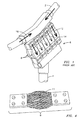
- Fig. 4 illustrates a typical, uncovered flexible connector.
- Fig. 5 illustrates a FCA with an eccentrically placed terminal lead.
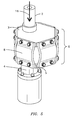
- Fig. 6 illustrates how multiple FCA with eccentrically placed terminal leads are arranged according to one embodiment of the present invention.
- the present invention deals with flexible connector assemblies (FCA), and more particularly with FCA that have increased current capacity due to a more uniform current distribution within the flexible connector subcomponents amongst multiple neighboring FCA.
- FCA flexible connector assemblies
- FCA flexible connector assemblies
- the disrupting effects of the magnetic flux caused by neighboring conductors can be reduced, therefore allowing a more uniform flow of electrical current through the flexible connectors in a given FCA.
- a single main lead that is centrally connected to a single FCA will evenly distribute current flow among the flexible connectors in that FCA.
- the magnetic flux generated by the neighboring FCA will disrupt the uniformity of current flow distribution among the flexible connectors.
- Flexible connectors are the point in the assembly that allows for a difference of movement between adjacent, less flexible conductors. Flexible connectors tend to be cooled less intensively than other electrical conductors in the assembly. Thus minimizing electrical losses in the connectors is important. Losses are minimized if the electrical currents are distributed uniformly among the flexible connectors in a given FCA. Flexible connectors are made primarily out of copper and copper alloys, but other material may be used as well. The flexibility in the flexible connector comes from the central braided portion 11, as shown in Fig. 4 . This braided portion is typically covered by a plastic sheath to preserve integrity, as is depicted in the other figures. A typical Penn Union TM flexible connector will allow for lateral movement of about three quarters of an inch, depending upon model type and how the flexible connector is installed.
- the present invention attaches the terminal conductors to the FCA eccentrically, in other words, off-center.
- This off-center placement actually allows for a more even flow of electrical current through the flexible connectors.
- the leads are placed as far from center on the FCA plates as possible to allow for maximum distance from other, neighboring FCA.
- a balance between resistive and inductive effects can be reached and the deleterious effects caused by neighboring assemblies are mostly canceled.
- the eccentric lead will distribute the passing current substantially more uniformly. This is because the magnetic flux created by a given FCA (inductive effects) disrupts the current distribution within its neighbors.
- FCA 6 an FCA 6 according to one embodiment of the present invention is shown.
- the terminal leads 2, 4 are eccentrically attached to the assembly's top 3 and bottom 5 plates.
- the top plate refers to the plate that is connected to the main lead and the bottom plate refers to the plate that is connected to the bushing.
- the exact distance of how far off-center the leads are connected will depends on the overall design of the generator terminal assembly. A more diffuse array of FCA will require a relatively small off-set, while a closely-spaced array will require a relatively large off-set.
- the precise location of the offset is determined by an accurate electromagnetic analysis of the design. Such an electromagnetic analysis is used to determine the dependence of the flexible connector current fraction upon the connector assembly offset. Subject to spatial constraints imposed by the entire generator terminal assembly, the offset that is chosen is the offset that results in distributing electrical current as evenly as possible among the flexible connectors in the FCA
- Fig. 6 illustrates a simplified plan view of the FCA top (or bottom) plates in a 3-phase lead box 20 from Fig. 3 .
- the leads 2 are attached to the FCA 6 and separated longitudinally, but otherwise are the same distances apart transversely.
- eccentric placement of the leads then have to be orientated vis a vis the other FCA, and the distance d is chosen in response to electromagnetic influences of neighboring FCA.
- inductive effects of adjacent FCA are generally disruptive (i.e. causing nonuniform distribution of electrical currents among the flexible connectors in a given FCA), and since these inductive effects are intensified as the distance between adjacent leads is reduced, a basic principle is to have the leads arranged as far apart as possible to minimize these inductive influences.
- FCA in hydrogen inner-cooled generators are typically Penn Union TM 2" x 6"x 1 ⁇ 2" copper flexible connectors.
- the flexible connectors may be attached by a variety of techniques known in the art such as riveting, hooking, brazing and clamping. Typically, however, they are bolted. This allows for flexibility in movement between the two conductors while maintaining sufficient electrical continuity.
- the invention may be practiced on different models and scales as required.
- the present invention may be practiced on indirectly cooled generators ranging from 190 MVA to 550 MVA, hydrogen directly cooled generators ranging from 100 to 1000 MVA and water cooled generators ranging from 500 MVA to 2200 MVA.
- An expected use of the present invention is to be in the 2000 MVA water cooled generator now being produced by Siemens Power Generation TM for an advanced design nuclear power station in Finland.
- the present invention provides for an FCA apparatus that comprises a first terminal lead 2, a second terminal lead 4, and a top 3 and bottom 5 plate connected by flexible connectors 8.
- the first terminal lead is connected to the top plate eccentrically and a current 16 passes into the FCA 6 through the first terminal lead, and the current is substantially evenly distributed through the flexible connectors.
- the second terminal lead 4 is also connected to the bottom plate 5 eccentrically, reflecting the placement of the first terminal lead.
- the FCA is part of a hydrogen inner-cooled generator or a water-cooled generator.
- the flexible connectors are evenly spaced around the FCA, and the total current carrying capacity of the FCA is approximately 50,000 amps. In some embodiments at least six flexible connectors are used in the FCA.
- the first terminal lead 3 is connected to the top plate 3 at a prescribed distance from center. If a plurality of FCA 6 are used within a generator, and the eccentric placement of the first terminal lead relative to the eccentric placement of other first terminal leads on other FC apparatuses maintain a maximum distance between the first terminal leads along the generator's longitudinal axis.
- the present invention provides for a multiple FCA apparatus 20 where each of the FCA comprise a first terminal lead 2, a second terminal lead 4, a top plate 3 and bottom 5 plate joined by flexible connectors 8.
- the terminal leads are connected to the plates eccentrically and in a similar position relative to each other.
- a current passes into the FCA 6 through the first terminal lead.
- the multiple FCA are aligned in a transverse and longitudinal direction within a generator and the eccentrically placed leads are oriented at maximum distance away from the other eccentrically placed leads on other FCA along either the transverse or longitudinal direction.
- each FCA comprises the same number of flexible connectors, which in many embodiments is six.
- a method of 6 connecting a first conductor 2 with a second conductor 4 through an FCA provides for eccentrically attaching a terminal lead of the first conductor to a top plate 3 in the FCA 6. Then aligning the second connector to a matching location on a bottom plate 5 of the FCA and attaching a terminal lead of the second connector to the bottom plate.
- both the terminal leads are attached to the FCA as far from center as possible without adversely affecting potential for current flow through the FCA. Also the leads may be orientated from a neighboring FCA.
Landscapes
- Engineering & Computer Science (AREA)
- Power Engineering (AREA)
- Motor Or Generator Frames (AREA)
Applications Claiming Priority (1)
| Application Number | Priority Date | Filing Date | Title |
|---|---|---|---|
| US11/807,391 US7575455B2 (en) | 2007-05-29 | 2007-05-29 | Eccentric polygonal main lead flexible connector assembly |
Publications (1)
| Publication Number | Publication Date |
|---|---|
| EP1998426A2 true EP1998426A2 (de) | 2008-12-03 |
Family
ID=39766148
Family Applications (1)
| Application Number | Title | Priority Date | Filing Date |
|---|---|---|---|
| EP08155577A Withdrawn EP1998426A2 (de) | 2007-05-29 | 2008-05-02 | Exzentrische, flexible Polygonsteckeranordnung für Hauptleitungen |
Country Status (2)
| Country | Link |
|---|---|
| US (1) | US7575455B2 (de) |
| EP (1) | EP1998426A2 (de) |
Families Citing this family (2)
| Publication number | Priority date | Publication date | Assignee | Title |
|---|---|---|---|---|
| JP5668983B2 (ja) * | 2011-04-05 | 2015-02-12 | 株式会社オートネットワーク技術研究所 | コネクタ |
| DE102015113123B4 (de) * | 2015-08-10 | 2017-03-16 | Sma Solar Technology Ag | Vorrichtung zur Herstellung einer mehrphasigen elektrischen Verbindung sowie eine Anordnung mit entsprechenden Vorrichtungen |
Family Cites Families (13)
| Publication number | Priority date | Publication date | Assignee | Title |
|---|---|---|---|---|
| US833290A (en) * | 1904-11-30 | 1906-10-16 | Anson Gardner Betts | Electrical conductor. |
| US1588556A (en) * | 1921-03-14 | 1926-06-15 | Westinghouse Electric & Mfg Co | Expansion connecter |
| US1759567A (en) * | 1928-09-07 | 1930-05-20 | Dibner Abraham Bernard | Slide joint for electrical conductors |
| US3325588A (en) * | 1965-06-10 | 1967-06-13 | Westinghouse Electric Corp | Removable bus conductor connector |
| US4204085A (en) * | 1978-05-26 | 1980-05-20 | Gould Inc. | Seismic-proof bus duct joint |
| US5736670A (en) * | 1994-09-28 | 1998-04-07 | Westinghouse Electric Corporation | Flexible gas tight electrical connection for generators |
| US5957717A (en) * | 1996-11-26 | 1999-09-28 | Trimble Navigation Limited | Range pole with integrated power system |
| US6200206B1 (en) * | 1998-10-05 | 2001-03-13 | Edward Drees | Surface preparation device |
| US6538339B2 (en) * | 2000-03-02 | 2003-03-25 | Siemens Westinghouse Power Corporation | Power generation system interchangeability device and related methods |
| US6439907B1 (en) * | 2001-07-20 | 2002-08-27 | Siemens Westinghouse Power Corporation | Generator junction assembly |
| US6649826B1 (en) * | 2001-07-20 | 2003-11-18 | Siemens Westinghouse Power Corporation | Gas cooled electrical junction assembly |
| US6948939B1 (en) * | 2004-06-17 | 2005-09-27 | Siemens Westinghouse Power Corporation | Method and apparatus for a multiple fin style current connector |
| US7400072B2 (en) * | 2004-12-10 | 2008-07-15 | Siemens Power Generation, Inc. | Bolted spherical series and phase connector for stator coils of electrical generators |
-
2007
- 2007-05-29 US US11/807,391 patent/US7575455B2/en not_active Expired - Fee Related
-
2008
- 2008-05-02 EP EP08155577A patent/EP1998426A2/de not_active Withdrawn
Also Published As
| Publication number | Publication date |
|---|---|
| US20080299785A1 (en) | 2008-12-04 |
| US7575455B2 (en) | 2009-08-18 |
Similar Documents
| Publication | Publication Date | Title |
|---|---|---|
| US20210151247A1 (en) | Coil Winding, Coil Module, Transmitting Apparatus, Receiving Apparatus, System, and Terminal | |
| US12020857B2 (en) | Coil module, wireless charging transmitting apparatus, wireless charging receiving apparatus, wireless charging system, and terminal | |
| CN102347660B (zh) | 定子中的多导体线圈 | |
| RU2497221C2 (ru) | Блок плавких предохранителей | |
| KR20180063238A (ko) | 인쇄 회로 기판 고정자 내의 열 관리를 위한 구조체 및 방법 | |
| KR20190009120A (ko) | 버스바조립체 및 그 제조방법 | |
| US12062879B2 (en) | Partitioned cable joint for superconducting cables | |
| GB2231723A (en) | Contact arrangement for a vacuum switch | |
| US7575455B2 (en) | Eccentric polygonal main lead flexible connector assembly | |
| US10193284B2 (en) | Device for establishing a multi-phase electric connection and an arrangement comprising corresponding devices | |
| US10056788B2 (en) | Wireless transmission device | |
| US6236209B1 (en) | Actively shielded, transversal gradient coil system with 3D connection technology | |
| EP1953767A2 (de) | Anordnung zur Übertragung von Mehrphasenstrom | |
| KR20110067101A (ko) | 이상 전자 펄스로부터 전력 시스템을 보호하는 방법 및 장치 | |
| US6948939B1 (en) | Method and apparatus for a multiple fin style current connector | |
| US6911833B2 (en) | Electromagnetically shielded test contactor | |
| US10251294B2 (en) | Power supply structure | |
| US20240235070A1 (en) | Multi-Dimensional, Flux-Excluding, Low-Inductance Electrical Interconnect | |
| US4754390A (en) | Conductively cooled switching regulator | |
| WO2023162751A1 (ja) | 電池パック | |
| CN109565944A (zh) | 用于大功率变流器的相位模块 | |
| US20200364808A1 (en) | Service switch for utility meter | |
| KR102827550B1 (ko) | 전원을 인덕터에 연결하기 위한 디바이스 | |
| US20130288498A1 (en) | Connector for multi-phase conductors | |
| US20260074092A1 (en) | Cable Unit for Connecting a Gradient Coil to a Power Amplifier |
Legal Events
| Date | Code | Title | Description |
|---|---|---|---|
| PUAI | Public reference made under article 153(3) epc to a published international application that has entered the european phase |
Free format text: ORIGINAL CODE: 0009012 |
|
| AK | Designated contracting states |
Kind code of ref document: A2 Designated state(s): AT BE BG CH CY CZ DE DK EE ES FI FR GB GR HR HU IE IS IT LI LT LU LV MC MT NL NO PL PT RO SE SI SK TR |
|
| AX | Request for extension of the european patent |
Extension state: AL BA MK RS |
|
| STAA | Information on the status of an ep patent application or granted ep patent |
Free format text: STATUS: THE APPLICATION HAS BEEN PUBLISHED |
|
| STAA | Information on the status of an ep patent application or granted ep patent |
Free format text: STATUS: THE APPLICATION IS DEEMED TO BE WITHDRAWN |
|
| 18D | Application deemed to be withdrawn |
Effective date: 20161201 |