EP1998304A1 - Method and system for monitoring vehicle transit along a highway section - Google Patents
Method and system for monitoring vehicle transit along a highway section Download PDFInfo
- Publication number
- EP1998304A1 EP1998304A1 EP07425303A EP07425303A EP1998304A1 EP 1998304 A1 EP1998304 A1 EP 1998304A1 EP 07425303 A EP07425303 A EP 07425303A EP 07425303 A EP07425303 A EP 07425303A EP 1998304 A1 EP1998304 A1 EP 1998304A1
- Authority
- EP
- European Patent Office
- Prior art keywords
- power
- wireless signal
- value
- transmitting
- vehicle
- Prior art date
- Legal status (The legal status is an assumption and is not a legal conclusion. Google has not performed a legal analysis and makes no representation as to the accuracy of the status listed.)
- Granted
Links
Images
Classifications
-
- G—PHYSICS
- G08—SIGNALLING
- G08G—TRAFFIC CONTROL SYSTEMS
- G08G1/00—Traffic control systems for road vehicles
- G08G1/01—Detecting movement of traffic to be counted or controlled
- G08G1/015—Detecting movement of traffic to be counted or controlled with provision for distinguishing between two or more types of vehicles, e.g. between motor-cars and cycles
-
- G—PHYSICS
- G01—MEASURING; TESTING
- G01S—RADIO DIRECTION-FINDING; RADIO NAVIGATION; DETERMINING DISTANCE OR VELOCITY BY USE OF RADIO WAVES; LOCATING OR PRESENCE-DETECTING BY USE OF THE REFLECTION OR RERADIATION OF RADIO WAVES; ANALOGOUS ARRANGEMENTS USING OTHER WAVES
- G01S13/00—Systems using the reflection or reradiation of radio waves, e.g. radar systems; Analogous systems using reflection or reradiation of waves whose nature or wavelength is irrelevant or unspecified
- G01S13/003—Bistatic radar systems; Multistatic radar systems
-
- G—PHYSICS
- G01—MEASURING; TESTING
- G01S—RADIO DIRECTION-FINDING; RADIO NAVIGATION; DETERMINING DISTANCE OR VELOCITY BY USE OF RADIO WAVES; LOCATING OR PRESENCE-DETECTING BY USE OF THE REFLECTION OR RERADIATION OF RADIO WAVES; ANALOGOUS ARRANGEMENTS USING OTHER WAVES
- G01S13/00—Systems using the reflection or reradiation of radio waves, e.g. radar systems; Analogous systems using reflection or reradiation of waves whose nature or wavelength is irrelevant or unspecified
- G01S13/02—Systems using reflection of radio waves, e.g. primary radar systems; Analogous systems
- G01S13/04—Systems determining presence of a target
Definitions
- the present invention relates to a method and system for monitoring vehicle transit along a highway section.
- Vehicle transit along a highway section is monitored by systems based on transmitting-receiving stations, which transmit directional signals, with given spectral characteristics, onto the monitored highway section, and detect vehicle passage on the basis of the characteristics of the signals reflected by the vehicles in transit which, in passing, alter the signal transmitted by the transmitting-receiving stations.
- transmitting-receiving stations which transmit directional signals, with given spectral characteristics, onto the monitored highway section, and detect vehicle passage on the basis of the characteristics of the signals reflected by the vehicles in transit which, in passing, alter the signal transmitted by the transmitting-receiving stations.
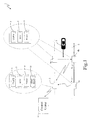
- Number 1 in Figure 1 indicates as a whole a system for monitoring vehicle transit along a highway section 2, and implementing the monitoring method according to the present invention.
- the highway section 2 shown schematically in Figure 1 is a lane of a one-way highway, e.g. motorway or main road, travelled by vehicles, e.g. vehicle 3.
- a one-way highway e.g. motorway or main road
- vehicles e.g. vehicle 3.
- monitoring system 1 comprises:
- each pair of transmitting-receiving stations 4a, 4b of the wireless sensor network installed on opposite sides of highway section 2 is configured to detect passage of vehicle 3 along highway section 2, to type-classify the vehicles in transit on the basis of a wireless signal transmitted by transmitting-receiving station 4a, and to transmit the vehicle transit and type information to Gateway station 5.
- Transmitting-receiving stations 4c are configured exclusively to transmit the vehicle transit and type information, processed by transmitting-receiving station 4b, to Gateway station 5, which transmits the information to remote control centre 6.
- transmitting-receiving stations 4a, 4b, 4c preferably all have the same hardware configuration, and each comprise:
- each transmitting-receiving station 4a comprises a sensor or device (not shown), e.g. a microphone or television camera, for detecting arrival of vehicle 3, and its transmitting-receiving unit 8 is configured to transmit a directional wireless signal S t(i) , of given spectral characteristics and power, to transmitting-receiving station 4b.
- a sensor or device not shown
- S t(i) a directional wireless signal
- transmitting-receiving unit 8 and control and processing unit 7 of each transmitting-receiving station 4b are configured, respectively, to receive the wireless signal S t(i) from transmitting-receiving station 4a, and to control operation of station 4b and process the incoming signal S t(i) , in accordance with the method of the invention, to determine transit of vehicle 3 along highway section 2, and type-classify the vehicle in transit.
- transmitting-receiving Gateway station 5 may be, for example, a GSM or WI/FI transmitting-receiving unit, which transmits the vehicle transit and type information to remote control centre 6, where the information is stored and analysed.
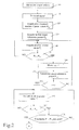
- the algorithm Since vehicle passage is determined by analysing the power of the signal received by transmitting-receiving station 4b when the system is turned on, the algorithm provides for calculating a mean power value or so-called “reference power", with which the instantaneous power is compared.
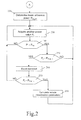
- a method step is performed to eliminate wireless signals received in the presence of signal-power-reducing interference, and to determine a mean reference power value P mi-ref of wireless signal S t(i) , that can be relied on to detect vehicle transit along highway section 2 and type-classify the vehicles.
- transmitting-receiving unit 8 of transmitting-receiving station 4a begins transmitting wireless signal S t(i) - e.g. a 433 MHz, 868 MHz, or 2.4 GHz signal - at regular time intervals ⁇ t of, say, 100 ms (block 110).
- Wireless signal S t(i) is received by transmitting-receiving unit 8 of station 4b, which acquires and memorizes, in its control and processing unit 7, a number of power values P 1..n of a number of incoming wireless signals S t(i) , e.g. the power values of the first 50 signals S t(1..50) (block 120).
- control and processing unit 7 of station 4b calculates and memorizes a first mean reference power P m1 of wireless signal S t(i) (block 130).
- first mean reference power P m1 cannot be relied on, in that, in the event transmitting-receiving station 4a is turned on while a vehicle is passing, the signals S t(i) transmitted while the vehicle is between transmitting-receiving stations 4a and 4b would be attenuated by the vehicle, and would reach transmitting-receiving unit 8 of station 4b with a power level too low to determine the mean reference power P mi of signal S t(i) .
- control and processing unit 7 of station 4b After acquiring the first 50 power values P 1..50 of the first 50 incoming signals, therefore, control and processing unit 7 of station 4b, to check the reliability of the calculated first mean reference power P m1 , acquires another power value P i of signal S t(i) (block 140), compares it with the calculated first mean reference power P m1 (block 150), and, if power P i of signal S t(i) is less than first mean reference power P m1 (NO output of block 150), rejects value P i of signal S t(i) , and repeats the steps of blocks 140 and 150 to acquire the power values P i of successive signals S t(i) until a signal S t(i) is acquired with a power P i greater than or equal to first mean reference power P m1 .
- control and processing unit 7 of station 4b eliminates the oldest power value in the group of power values P 1..50 , replaces it with the power value P i greater than or equal to first mean reference power P m1 (block 160), and calculates a second mean reference power P mi on the basis of the power values P 2..50 still in the memory, and of power P i greater than or equal to the first mean reference power (block 170).
- control and processing unit 7 of station 4b determines whether the number of power values P i memorized in block 160 equals the number of power values P 1..n , e.g. 50, memorized in block 120. If it does not (NO output of block 180), block 180 goes back to block 140, which acquires another power value P i . And the block 140-180 procedure is repeated by control and processing unit 7 of station 4b until the number of power values P i memorized in block 160 equals the number of power values P 1..n , e.g. 50, memorized in block 120.
- the reliable mean reference power value P mi-ref by which control and processing unit 7 of station 4b detects vehicle transit along highway section 2, is obtained.
- control and processing unit 7 of station 4b compares each new power value P i of signal S t(i) acquired in block 190 with the last value of the calculated second mean reference power P mi , and memorizes all the new power values P i greater than the last mean reference power P mi . If the new power value P i acquired in block 190 is less than or equal to the last mean reference power P mi , control and processing unit 7 of station 4b rejects the new power value P i acquired, and repeats the block 190-200 procedure.
- control and processing unit 7 of station 4b determines whether the number of power values P i greater than the last calculated mean reference power P mi exceeds a given threshold value, e.g. 100. If it does not (NO output of block 210), block 210 goes back to block 190, which acquires a new power value P i . If it does (YES output of block 210), in block 220, control and processing unit 7 of station 4b determines the value of mean reference power P mi-ref on the basis of the power values Pi acquired in block 200 and greater than second mean reference power P mi .
- a given threshold value e.g. 100.
- the purpose of the block 190-210 procedure of determining mean reference power P mi-ref is to ensure a reliable mean reference power value by which to detect vehicle transit along the highway section, and to eliminate the effect of factors - such as accidental variations in power values P i of signal S t(i) and/or weather conditions, e.g. rain, fog, etc., causing a reduction in power P i of signal S t(i) - which would result in a variation of mean reference power P mi-ref .
- mean reference power P mi-ref were determined on the basis of power values P i which, due to accidental variations, are lower than mean reference power P mi , system operation could be compromised, in that a variation in power caused by an accidental event starts and ends sharply, and only lasts for a few consecutive signals S t(i) . Consequently, if mean reference power P mi were updated using these values, its own value would be seriously altered.
- Control and processing unit 7 of station 4b in fact, being unable to recognize an accidental event beforehand, would in no way react to a sharp variation in power P i with respect to normal values, but would use these values to calculate mean reference power P mi-ref , thus altering its value and so impairing the reliability of monitoring system 1, which would no longer be able to accurately determine the start and end of passage of vehicle 3.
- control and processing unit 7 of station 4b can therefore start detecting vehicle transit along highway section 2.
- control and processing unit 7 of station 4b acquires a new power value P i (block 230), compares it with mean reference power P mi-ref , and, if it is greater than or equal to mean reference power value P mi-ref (NO output of block 240), rejects it, on the grounds of it indicating no vehicle travelling along highway section 2, and block 240 goes back to block 230, which acquires the next power value P i . Conversely, if power value P i is less than mean reference power P mi-ref , this means vehicle 3 is probably travelling along monitored highway section 2.
- control and processing unit 7 of station 4b determines (block 250) whether power P i of the incoming signal S t(i) is below a predetermined first threshold value P trsh1 indicating an event. If power P i of the incoming signal S t(i) is greater than or equal to first threshold value P trsh1 , the current power value P i is rejected, by being irrelevant for vehicle transit detection purposes, and block 250 goes back to block 230, which acquires power value P i of the next signal S t(i) .
- control and processing unit 7 of station 4b classifies the event (block 260), and determines whether power P i of the incoming signal S t(i) is also below a predetermined second threshold value P trsh2 indicating transit of a vehicle along highway section 2.
- block 270 goes back to block 230, which acquires the next power value P i , in that the reduction in power P i has been caused by an event, as opposed to transit of a vehicle.
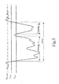
- FIG. 3 shows the two threshold values P trsh1 , P trsh2 , and the pattern of power P i of signals S t(i) during transit of a vehicle.
- the Figure 3 example shows a mean reference power P mi-ref level (shown by the dot-and-dash line); a first threshold value P trsh1 level indicating an event; a second threshold value P trsh2 level indicating passage of a vehicle (not shown) along the highway section; and the variation in mean reference power P mi-ref of signal S t(i) caused by passage of a vehicle.
- mean reference power P mi-ref of signal S t(i) is first attenuated and exceeds first threshold value P trsh1 indicating an event, i.e. approach of the vehicle, and then falls sharply to also exceed second threshold value P trsh2 as the vehicle travels past stations 4a and 4b.
- the method according to the invention has the main advantage of being easy to implement, and highly reliably monitoring vehicle transit along a highway section.
Landscapes
- Engineering & Computer Science (AREA)
- Radar, Positioning & Navigation (AREA)
- Remote Sensing (AREA)
- Physics & Mathematics (AREA)
- General Physics & Mathematics (AREA)
- Computer Networks & Wireless Communication (AREA)
- Traffic Control Systems (AREA)
- Mobile Radio Communication Systems (AREA)
- Road Signs Or Road Markings (AREA)
- Monitoring And Testing Of Transmission In General (AREA)
Abstract

Description
- The present invention relates to a method and system for monitoring vehicle transit along a highway section.
- Vehicle transit along a highway section, e.g. preferential city or motorway lanes, is monitored by systems based on transmitting-receiving stations, which transmit directional signals, with given spectral characteristics, onto the monitored highway section, and detect vehicle passage on the basis of the characteristics of the signals reflected by the vehicles in transit which, in passing, alter the signal transmitted by the transmitting-receiving stations.
- The efficiency of these systems, and the methods implemented by them, depends closely on the quality of the incoming signals, which is seriously affected by interference, weather conditions, etc.
- It is an object of the present invention to provide a method and system for monitoring vehicle transit along a highway section, designed to ensure reliable operation and precise detection of vehicle transit, regardless of incoming signal quality.
- According to the present invention, there are provided a method and system for monitoring vehicle transit along a highway section, as claimed in the accompanying Claims.
- A preferred, non-limiting embodiment of the present invention will be described by way of example with reference to the accompanying drawings, in which:
-
Figure 1 shows a schematic of a monitoring system implementing the method according to the present invention; -
Figure 2 shows a flow chart of the monitoring method according to the present invention; -
Figure 3 shows variations in the power level of a signal, on which detection of vehicle transit along a highway section is based. -
Number 1 inFigure 1 indicates as a whole a system for monitoring vehicle transit along ahighway section 2, and implementing the monitoring method according to the present invention. - By way of a non-limiting example, the
highway section 2 shown schematically inFigure 1 is a lane of a one-way highway, e.g. motorway or main road, travelled by vehicles,e.g. vehicle 3. - More specifically,
monitoring system 1 according to the invention comprises: - a known self-configuring wireless sensor network comprising a number of transmitting-
receiving stations highway section 2, and are configured to communicate with one other by known communication protocols specific to this type of network, and to perform specific functions as described below; - a transmitting-receiving
Gateway station 5 located close to the monitoredhighway section 2 to collect information from transmitting-receivingstations - a remote control centre 6 communicating with Gateway
station 5. - More specifically, each pair of transmitting-receiving
stations highway section 2 is configured to detect passage ofvehicle 3 alonghighway section 2, to type-classify the vehicles in transit on the basis of a wireless signal transmitted by transmitting-receivingstation 4a, and to transmit the vehicle transit and type information toGateway station 5. - Transmitting-
receiving stations 4c, on the other hand, are configured exclusively to transmit the vehicle transit and type information, processed by transmitting-receivingstation 4b, toGateway station 5, which transmits the information to remote control centre 6. As shown in the enlarged detail inFigure 1 , transmitting-receiving stations - a control and
processing unit 7 configured to control operation of transmitting-receivingstation - a transmitting-receiving
unit 8; and - an
independent power source 9. - The specific functions of transmitting-
receiving stations processing unit 7 of eachstation receiving station 4a comprises a sensor or device (not shown), e.g. a microphone or television camera, for detecting arrival ofvehicle 3, and its transmitting-receivingunit 8 is configured to transmit a directional wireless signal St(i), of given spectral characteristics and power, to transmitting-receivingstation 4b. - More specifically, transmitting-receiving
unit 8 and control andprocessing unit 7 of each transmitting-receiving station 4b are configured, respectively, to receive the wireless signal St(i) from transmitting-receivingstation 4a, and to control operation ofstation 4b and process the incoming signal St(i), in accordance with the method of the invention, to determine transit ofvehicle 3 alonghighway section 2, and type-classify the vehicle in transit. - More specifically, transmitting-receiving
Gateway station 5 may be, for example, a GSM or WI/FI transmitting-receiving unit, which transmits the vehicle transit and type information to remote control centre 6, where the information is stored and analysed. - More specifically, vehicles in transit along monitored
highway section 2 are detected and type-classified in accordance with the method of the invention, the various steps of which are shown in theFigure 2 flow chart. - Since vehicle passage is determined by analysing the power of the signal received by transmitting-receiving
station 4b when the system is turned on, the algorithm provides for calculating a mean power value or so-called "reference power", with which the instantaneous power is compared. - When transmitting-receiving
stations highway section 2 and type-classify the vehicles. - Accordingly, when
stations unit 8 of transmitting-receivingstation 4a begins transmitting wireless signal St(i) - e.g. a 433 MHz, 868 MHz, or 2.4 GHz signal - at regular time intervals Δt of, say, 100 ms (block 110). - Wireless signal St(i) is received by transmitting-receiving
unit 8 ofstation 4b, which acquires and memorizes, in its control andprocessing unit 7, a number of power values P1..n of a number of incoming wireless signals St(i), e.g. the power values of the first 50 signals St(1..50) (block 120). - On the basis of the 50 memorized power values Pi..n , control and
processing unit 7 ofstation 4b then calculates and memorizes a first mean reference power Pm1 of wireless signal St(i) (block 130). - The value of first mean reference power Pm1, however, cannot be relied on, in that, in the event transmitting-receiving
station 4a is turned on while a vehicle is passing, the signals St(i) transmitted while the vehicle is between transmitting-receivingstations unit 8 ofstation 4b with a power level too low to determine the mean reference power Pmi of signal St(i) . - After acquiring the first 50 power values P1..50 of the first 50 incoming signals, therefore, control and
processing unit 7 ofstation 4b, to check the reliability of the calculated first mean reference power Pm1, acquires another power value Pi of signal St(i) (block 140), compares it with the calculated first mean reference power Pm1 (block 150), and, if power Pi of signal St(i) is less than first mean reference power Pm1 (NO output of block 150), rejects value Pi of signal St(i), and repeats the steps ofblocks - In which case, control and
processing unit 7 ofstation 4b eliminates the oldest power value in the group of power values P1..50, replaces it with the power value Pi greater than or equal to first mean reference power Pm1 (block 160), and calculates a second mean reference power Pmi on the basis of the power values P2..50 still in the memory, and of power Pi greater than or equal to the first mean reference power (block 170). - In
block 180, control andprocessing unit 7 ofstation 4b determines whether the number of power values Pi memorized inblock 160 equals the number of power values P1..n, e.g. 50, memorized inblock 120. If it does not (NO output of block 180),block 180 goes back toblock 140, which acquires another power value Pi . And the block 140-180 procedure is repeated by control andprocessing unit 7 ofstation 4b until the number of power values Pi memorized inblock 160 equals the number of power values P1..n, e.g. 50, memorized inblock 120. - By the end of the block 140-180 procedure, the reliable mean reference power value Pmi-ref, by which control and
processing unit 7 ofstation 4b detects vehicle transit alonghighway section 2, is obtained. - At this point, in
block 200, control andprocessing unit 7 ofstation 4b compares each new power value Pi of signal St(i) acquired inblock 190 with the last value of the calculated second mean reference power Pmi, and memorizes all the new power values Pi greater than the last mean reference power Pmi. If the new power value Pi acquired inblock 190 is less than or equal to the last mean reference power Pmi, control andprocessing unit 7 ofstation 4b rejects the new power value Pi acquired, and repeats the block 190-200 procedure. - In
block 210, control andprocessing unit 7 ofstation 4b determines whether the number of power values Pi greater than the last calculated mean reference power Pmi exceeds a given threshold value, e.g. 100. If it does not (NO output of block 210),block 210 goes back toblock 190, which acquires a new power value Pi. If it does (YES output of block 210), inblock 220, control andprocessing unit 7 ofstation 4b determines the value of mean reference power Pmi-ref on the basis of the power values Pi acquired inblock 200 and greater than second mean reference power Pmi . - The purpose of the block 190-210 procedure of determining mean reference power Pmi-ref is to ensure a reliable mean reference power value by which to detect vehicle transit along the highway section, and to eliminate the effect of factors - such as accidental variations in power values Pi of signal St(i) and/or weather conditions, e.g. rain, fog, etc., causing a reduction in power Pi of signal St(i) - which would result in a variation of mean reference power Pmi-ref. In fact, if mean reference power Pmi-ref were determined on the basis of power values Pi which, due to accidental variations, are lower than mean reference power Pmi, system operation could be compromised, in that a variation in power caused by an accidental event starts and ends sharply, and only lasts for a few consecutive signals St(i). Consequently, if mean reference power Pmi were updated using these values, its own value would be seriously altered. Control and
processing unit 7 ofstation 4b, in fact, being unable to recognize an accidental event beforehand, would in no way react to a sharp variation in power Pi with respect to normal values, but would use these values to calculate mean reference power Pmi-ref, thus altering its value and so impairing the reliability ofmonitoring system 1, which would no longer be able to accurately determine the start and end of passage ofvehicle 3. - Once mean reference power Pmi-ref is determined, control and
processing unit 7 ofstation 4b can therefore start detecting vehicle transit alonghighway section 2. - Accordingly, control and
processing unit 7 ofstation 4b acquires a new power value Pi (block 230), compares it with mean reference power Pmi-ref, and, if it is greater than or equal to mean reference power value Pmi-ref (NO output of block 240), rejects it, on the grounds of it indicating no vehicle travelling alonghighway section 2, andblock 240 goes back toblock 230, which acquires the next power value Pi. Conversely, if power value Pi is less than mean reference power Pmi-ref, this meansvehicle 3 is probably travelling along monitoredhighway section 2. - More specifically, to determine whether
vehicle 3 is actually travelling along monitoredhighway section 2, or the reduction in power Pi with respect to mean reference power Pmi-ref has been caused by an accidental event, control andprocessing unit 7 ofstation 4b determines (block 250) whether power Pi of the incoming signal St(i) is below a predetermined first threshold value Ptrsh1 indicating an event. If power Pi of the incoming signal St(i) is greater than or equal to first threshold value Ptrsh1 , the current power value Pi is rejected, by being irrelevant for vehicle transit detection purposes, andblock 250 goes back toblock 230, which acquires power value Pi of the next signal St(i) . - Conversely (YES output of block 250), control and
processing unit 7 ofstation 4b classifies the event (block 260), and determines whether power Pi of the incoming signal St(i) is also below a predetermined second threshold value Ptrsh2 indicating transit of a vehicle alonghighway section 2. - If power Pi of the incoming signal St(i) is greater than second threshold value Ptrsh2 (NO output of block 270),
block 270 goes back toblock 230, which acquires the next power value Pi, in that the reduction in power Pi has been caused by an event, as opposed to transit of a vehicle. - If power Pi of the incoming signal St(i) is also below second threshold value Ptrsh2 (YES output of block 270), however, this means a vehicle is actually travelling along
highway section 2, soblock 270 goes on to ablock 280, in which control andprocessing unit 7 ofstation 4b calculates in known manner a set of parameters by which to type-classify the vehicle travelling alonghighway section 2. - The method steps in blocks 250-280 for detecting an event and/or vehicle transit along the monitored highway section are shown in
Figure 3 , which shows the two threshold values Ptrsh1, Ptrsh2, and the pattern of power Pi of signals St(i) during transit of a vehicle. - The
Figure 3 example shows a mean reference power Pmi-ref level (shown by the dot-and-dash line); a first threshold value Ptrsh1 level indicating an event; a second threshold value Ptrsh2 level indicating passage of a vehicle (not shown) along the highway section; and the variation in mean reference power Pmi-ref of signal St(i) caused by passage of a vehicle. - More specifically, as shown clearly in
Figure 3 , as the vehicle approaches, mean reference power Pmi-ref of signal St(i) is first attenuated and exceeds first threshold value Ptrsh1 indicating an event, i.e. approach of the vehicle, and then falls sharply to also exceed second threshold value Ptrsh2 as the vehicle travelspast stations - The method according to the invention has the main advantage of being easy to implement, and highly reliably monitoring vehicle transit along a highway section.
- Clearly, changes may be made to the method and system as described and illustrated herein without, however, departing from the scope of the present invention as defined in the accompanying Claims.
Claims (8)
- A method of monitoring transit of a vehicle (3) along a highway section (2), wherein a first transmitting-receiving station (4a) transmits a wireless signal to a second transmitting-receiving and processing station (4b); the travelling direction of said wireless signal being intersectable by the path of said vehicle; and the method comprising:- determining a reference power (Pmi-ref ) of a wireless signal (St(i) ) on the basis of a number of signals received by said second transmitting-receiving and processing station (4b), and by means of a procedure designed to eliminate signals received in the presence of interference which reduces the power of said wireless signal (St(i) ); and- detecting transit of said vehicle (3) along said highway section (2) on the basis of said reference power (Pmi-ref ).
- A method as claimed in Claim 1, wherein determining said reference power (Pmi-ref ) of said wireless signal (St(i) ) in the absence of interference comprises:- periodically transmitting a wireless signal (St(i) ) continuously from said first transmitting-receiving station (4a) to said second transmitting-receiving and processing station (4b);- receiving said wireless signal (St(i) ) at said second transmitting-receiving and processing station (4b), and determining a first power (Pi ) of the incoming said wireless signal (St(i) );- periodically and continuously acquiring said first power (Pi ) of the incoming said wireless signal (St(i) );- memorizing a number of periodically acquired values of said first power (P1..n ) of said wireless signal (St(i) );- determining, at said second transmitting-receiving and processing station (4b), a second power (Pm1 ) of said wireless signal (St(i) ) on the basis of said number of memorized values of said first power (P1..n );- determining a third power (Pmi ) of said wireless signal (St(i) ) on the basis of said number of memorized values of said first power (P1..n ), and on the basis of values of said first power (Pi ) greater than or equal to said second power (Pm1 ); and- determining said reference power (Pmi-ref ) on the basis of said third power (Pmi ) of said wireless signal (St(i) ).
- A method as claimed in Claim 2, wherein determining said reference power (Pmi-ref ) of said wireless signal (St(i) ) in the absence of interference also comprises:a) acquiring a value of said first power (Pi ) of said wireless signal (St(i) );b) comparing said value of said first power (Pi ) with said third power (Pmi );c) eliminating said value of said first power (Pi ), if said value of said first power (Pi ) is less than or equal to said third power (Pmi );d) acquiring a value of said first power (Pi ) until said value of said first power (Pi ) is greater than said third power (Pmi );e) memorizing said values of said first power (Pi ) greater than said third power (Pmi );f) repeating steps a) to e) until the number of values of said first power (Pi ) greater than said third power (Pmi ) equals the number of values used to determine said third power (Pmi ); andg) determining said reference power (Pmi-ref ) on the basis of said number of values of said first power (Pi ) greater than said third power (Pmi ).
- A method as claimed in Claim 2, wherein said second power (Pm1) of said wireless signal (St(i) ) is determined on the basis of the mean of said number of memorized values of said first power (P1..n ).
- A method as claimed in Claim 1, wherein detecting transit of said vehicle along said highway section on the basis of said reference power (Pmi-ref ), determined in the absence of interference, of said wireless signal (St(i) ) comprises:- comparing each acquired value of said first power (Pi ) with said reference power (Pmi-ref ), determined in the absence of interference, of said wireless signal (St(i) ), with a first threshold value (Ptrsh1 ), and with a second threshold value (Ptrsn2 ); and- detecting transit of said vehicle along said highway section (2) on the basis of said comparison.
- A method as claimed in Claims 2 and 3, wherein determining said third power (Pmi ) of said wireless signal (S t(i) ) comprises:a) acquiring a value of said first power (Pi );b) comparing said value of said first power (Pi ) with said second power (Pm1 );c) eliminating said value of said first power (Pi ), if said value of said first power (Pi ) is less than said second power (Pm1 );d) acquiring the next value of said first power (Pi ) until said value of said first power (Pi ) is greater than or equal to said second power (Pm1 );e) eliminating the oldest value of said first power (Pi ) from said number of memorized values of said first power (P1..n );f) replacing said oldest value of said first power (Pi ) with said value of said first power (Pi ) greater than or equal to said second power (Pm1 ); andg) repeating steps d) to f) until the number of values of said first power (Pi ) greater than or equal to said second power (Pm1) equals the number of values of said number of memorized values of said first power (P1..n ).
- A method as claimed in any one of the foregoing Claims, and comprising the step of classifying said vehicle (3) travelling along said highway section (2) on the basis of predetermined vehicle types.
- A system for monitoring transit of a vehicle (3) along a highway section (2), comprising:- a first transmitting-receiving station (4a) configured to transmit a wireless signal (St(i) ) whose travelling direction is intersectable by the path of said vehicle; and- a second transmitting-receiving and processing station (4b) configured to receive and process the wireless signal (St(i) ) transmitted by the first transmitting-receiving station (4a);characterized in that said first transmitting-receiving station (4a) and said second transmitting-receiving and processing station (4b) are configured to implement the method of monitoring transit of a vehicle (3) along a highway section (2) as claimed in any one of the foregoing Claims.
Priority Applications (3)
| Application Number | Priority Date | Filing Date | Title |
|---|---|---|---|
| AT07425303T ATE439662T1 (en) | 2007-05-21 | 2007-05-21 | SYSTEM FOR MONITORING VEHICLE TRAFFIC ON A MOTORWAY SECTION |
| EP07425303A EP1998304B1 (en) | 2007-05-21 | 2007-05-21 | System for monitoring vehicle transit along a highway section |
| DE602007001958T DE602007001958D1 (en) | 2007-05-21 | 2007-05-21 | System for monitoring vehicle traffic in a motorway section |
Applications Claiming Priority (1)
| Application Number | Priority Date | Filing Date | Title |
|---|---|---|---|
| EP07425303A EP1998304B1 (en) | 2007-05-21 | 2007-05-21 | System for monitoring vehicle transit along a highway section |
Publications (2)
| Publication Number | Publication Date |
|---|---|
| EP1998304A1 true EP1998304A1 (en) | 2008-12-03 |
| EP1998304B1 EP1998304B1 (en) | 2009-08-12 |
Family
ID=38577472
Family Applications (1)
| Application Number | Title | Priority Date | Filing Date |
|---|---|---|---|
| EP07425303A Not-in-force EP1998304B1 (en) | 2007-05-21 | 2007-05-21 | System for monitoring vehicle transit along a highway section |
Country Status (3)
| Country | Link |
|---|---|
| EP (1) | EP1998304B1 (en) |
| AT (1) | ATE439662T1 (en) |
| DE (1) | DE602007001958D1 (en) |
Cited By (2)
| Publication number | Priority date | Publication date | Assignee | Title |
|---|---|---|---|---|
| RU2617575C1 (en) * | 2016-04-14 | 2017-04-25 | Федеральное государственное казенное образовательное учреждение высшего образования "Калининградский пограничный институт Федеральной службы безопасности Российской Федерации" | Method of security monitoring |
| RU2621597C1 (en) * | 2016-04-14 | 2017-06-06 | Федеральное государственное казенное образовательное учреждение высшего образования "Калининградский пограничный институт Федеральной службы безопасности Российской Федерации" | Method of security monitoring of two nearby roads |
Citations (5)
| Publication number | Priority date | Publication date | Assignee | Title |
|---|---|---|---|---|
| GB2217545A (en) * | 1988-04-11 | 1989-10-25 | Shorrock Ltd | Intruder detection apparatus |
| US5210521A (en) * | 1990-07-26 | 1993-05-11 | Gary M. Hojell | Vehicle alarm apparatus and method for preventing injury to nearby persons |
| EP0860804A2 (en) * | 1997-02-19 | 1998-08-26 | Giovanni Gualdi | System for the detection and the signalling of objects on the roadway |
| US6417783B1 (en) * | 1997-02-05 | 2002-07-09 | Siemens Aktiengesellschaft | Motor vehicle detector |
| US20060232440A1 (en) * | 2005-08-02 | 2006-10-19 | Moreno Pieralli | Microwave Detection System and Method |
-
2007
- 2007-05-21 DE DE602007001958T patent/DE602007001958D1/en active Active
- 2007-05-21 EP EP07425303A patent/EP1998304B1/en not_active Not-in-force
- 2007-05-21 AT AT07425303T patent/ATE439662T1/en not_active IP Right Cessation
Patent Citations (5)
| Publication number | Priority date | Publication date | Assignee | Title |
|---|---|---|---|---|
| GB2217545A (en) * | 1988-04-11 | 1989-10-25 | Shorrock Ltd | Intruder detection apparatus |
| US5210521A (en) * | 1990-07-26 | 1993-05-11 | Gary M. Hojell | Vehicle alarm apparatus and method for preventing injury to nearby persons |
| US6417783B1 (en) * | 1997-02-05 | 2002-07-09 | Siemens Aktiengesellschaft | Motor vehicle detector |
| EP0860804A2 (en) * | 1997-02-19 | 1998-08-26 | Giovanni Gualdi | System for the detection and the signalling of objects on the roadway |
| US20060232440A1 (en) * | 2005-08-02 | 2006-10-19 | Moreno Pieralli | Microwave Detection System and Method |
Cited By (2)
| Publication number | Priority date | Publication date | Assignee | Title |
|---|---|---|---|---|
| RU2617575C1 (en) * | 2016-04-14 | 2017-04-25 | Федеральное государственное казенное образовательное учреждение высшего образования "Калининградский пограничный институт Федеральной службы безопасности Российской Федерации" | Method of security monitoring |
| RU2621597C1 (en) * | 2016-04-14 | 2017-06-06 | Федеральное государственное казенное образовательное учреждение высшего образования "Калининградский пограничный институт Федеральной службы безопасности Российской Федерации" | Method of security monitoring of two nearby roads |
Also Published As
| Publication number | Publication date |
|---|---|
| ATE439662T1 (en) | 2009-08-15 |
| DE602007001958D1 (en) | 2009-09-24 |
| EP1998304B1 (en) | 2009-08-12 |
Similar Documents
| Publication | Publication Date | Title |
|---|---|---|
| US7986247B2 (en) | Advisory system for previewing local conditions on a highway | |
| US10488506B2 (en) | Moving body recognition system | |
| JP7276670B2 (en) | DETECTION DEVICE, DETECTION METHOD AND DETECTION PROGRAM | |
| US9344856B2 (en) | Detection of false vehicle-to-vehicle emergency brake light messages | |
| KR101278024B1 (en) | Apparatus and method for classifying vehicle type and counting number of vehicles | |
| US20080306678A1 (en) | Travel History Collection System And Terminal Side Device Used For It | |
| JP2000504859A (en) | How to collect traffic data | |
| US20170110008A1 (en) | Traffic analysis system using wireless networking devices | |
| US20120161987A1 (en) | Apparatus and method for detecting vehicles | |
| US20160086486A1 (en) | Drive assist apparatus | |
| CN110155063B (en) | Tunnel detection system and method for motor vehicle, motor vehicle | |
| JP6274270B2 (en) | Information communication equipment | |
| US9842500B1 (en) | Warning system for an automated vehicle | |
| JPWO2020079874A1 (en) | Detection device, gateway device, detection method and detection program | |
| KR20140125482A (en) | Speeding enforcement method of vehicle using wireless communications | |
| US6339381B1 (en) | DSRC car-mounted equipment | |
| EP3633321A1 (en) | Lane assignment system | |
| EP1998304B1 (en) | System for monitoring vehicle transit along a highway section | |
| CN113810876A (en) | Vehicle-to-infrastructure communication control | |
| CN109444871B (en) | Pedestrian and animal detection method and device, computer equipment and storage medium | |
| JP2009169674A (en) | Traffic jam detection method, system and program | |
| US10300913B2 (en) | Vehicle identification device and vehicle identification method | |
| CN109416882B (en) | Determination of laterally remote parking spaces | |
| KR101916660B1 (en) | Apparatus for vehicle sensing using radar and infrared sensor and method thereof | |
| US20240182092A1 (en) | Railroad management system, track sensing device, track sensing method, control circuit, and storage medium |
Legal Events
| Date | Code | Title | Description |
|---|---|---|---|
| PUAI | Public reference made under article 153(3) epc to a published international application that has entered the european phase |
Free format text: ORIGINAL CODE: 0009012 |
|
| 17P | Request for examination filed |
Effective date: 20080429 |
|
| AK | Designated contracting states |
Kind code of ref document: A1 Designated state(s): AT BE BG CH CY CZ DE DK EE ES FI FR GB GR HU IE IS IT LI LT LU LV MC MT NL PL PT RO SE SI SK TR |
|
| AX | Request for extension of the european patent |
Extension state: AL BA HR MK RS |
|
| GRAP | Despatch of communication of intention to grant a patent |
Free format text: ORIGINAL CODE: EPIDOSNIGR1 |
|
| RTI1 | Title (correction) |
Free format text: SYSTEM FOR MONITORING VEHICLE TRANSIT ALONG A HIGHWAY SECTION |
|
| GRAS | Grant fee paid |
Free format text: ORIGINAL CODE: EPIDOSNIGR3 |
|
| GRAA | (expected) grant |
Free format text: ORIGINAL CODE: 0009210 |
|
| AK | Designated contracting states |
Kind code of ref document: B1 Designated state(s): AT BE BG CH CY CZ DE DK EE ES FI FR GB GR HU IE IS IT LI LT LU LV MC MT NL PL PT RO SE SI SK TR |
|
| REG | Reference to a national code |
Ref country code: GB Ref legal event code: FG4D |
|
| REG | Reference to a national code |
Ref country code: CH Ref legal event code: EP |
|
| REG | Reference to a national code |
Ref country code: IE Ref legal event code: FG4D |
|
| REF | Corresponds to: |
Ref document number: 602007001958 Country of ref document: DE Date of ref document: 20090924 Kind code of ref document: P |
|
| LTIE | Lt: invalidation of european patent or patent extension |
Effective date: 20090812 |
|
| PG25 | Lapsed in a contracting state [announced via postgrant information from national office to epo] |
Ref country code: FI Free format text: LAPSE BECAUSE OF FAILURE TO SUBMIT A TRANSLATION OF THE DESCRIPTION OR TO PAY THE FEE WITHIN THE PRESCRIBED TIME-LIMIT Effective date: 20090812 Ref country code: SE Free format text: LAPSE BECAUSE OF FAILURE TO SUBMIT A TRANSLATION OF THE DESCRIPTION OR TO PAY THE FEE WITHIN THE PRESCRIBED TIME-LIMIT Effective date: 20090812 Ref country code: AT Free format text: LAPSE BECAUSE OF FAILURE TO SUBMIT A TRANSLATION OF THE DESCRIPTION OR TO PAY THE FEE WITHIN THE PRESCRIBED TIME-LIMIT Effective date: 20090812 Ref country code: ES Free format text: LAPSE BECAUSE OF FAILURE TO SUBMIT A TRANSLATION OF THE DESCRIPTION OR TO PAY THE FEE WITHIN THE PRESCRIBED TIME-LIMIT Effective date: 20091123 Ref country code: IS Free format text: LAPSE BECAUSE OF FAILURE TO SUBMIT A TRANSLATION OF THE DESCRIPTION OR TO PAY THE FEE WITHIN THE PRESCRIBED TIME-LIMIT Effective date: 20091212 Ref country code: LT Free format text: LAPSE BECAUSE OF FAILURE TO SUBMIT A TRANSLATION OF THE DESCRIPTION OR TO PAY THE FEE WITHIN THE PRESCRIBED TIME-LIMIT Effective date: 20090812 |
|
| NLV1 | Nl: lapsed or annulled due to failure to fulfill the requirements of art. 29p and 29m of the patents act | ||
| PG25 | Lapsed in a contracting state [announced via postgrant information from national office to epo] |
Ref country code: NL Free format text: LAPSE BECAUSE OF FAILURE TO SUBMIT A TRANSLATION OF THE DESCRIPTION OR TO PAY THE FEE WITHIN THE PRESCRIBED TIME-LIMIT Effective date: 20090812 Ref country code: PL Free format text: LAPSE BECAUSE OF FAILURE TO SUBMIT A TRANSLATION OF THE DESCRIPTION OR TO PAY THE FEE WITHIN THE PRESCRIBED TIME-LIMIT Effective date: 20090812 Ref country code: SI Free format text: LAPSE BECAUSE OF FAILURE TO SUBMIT A TRANSLATION OF THE DESCRIPTION OR TO PAY THE FEE WITHIN THE PRESCRIBED TIME-LIMIT Effective date: 20090812 Ref country code: LV Free format text: LAPSE BECAUSE OF FAILURE TO SUBMIT A TRANSLATION OF THE DESCRIPTION OR TO PAY THE FEE WITHIN THE PRESCRIBED TIME-LIMIT Effective date: 20090812 |
|
| PG25 | Lapsed in a contracting state [announced via postgrant information from national office to epo] |
Ref country code: PT Free format text: LAPSE BECAUSE OF FAILURE TO SUBMIT A TRANSLATION OF THE DESCRIPTION OR TO PAY THE FEE WITHIN THE PRESCRIBED TIME-LIMIT Effective date: 20091212 Ref country code: BG Free format text: LAPSE BECAUSE OF FAILURE TO SUBMIT A TRANSLATION OF THE DESCRIPTION OR TO PAY THE FEE WITHIN THE PRESCRIBED TIME-LIMIT Effective date: 20091112 |
|
| PG25 | Lapsed in a contracting state [announced via postgrant information from national office to epo] |
Ref country code: DK Free format text: LAPSE BECAUSE OF FAILURE TO SUBMIT A TRANSLATION OF THE DESCRIPTION OR TO PAY THE FEE WITHIN THE PRESCRIBED TIME-LIMIT Effective date: 20090812 Ref country code: EE Free format text: LAPSE BECAUSE OF FAILURE TO SUBMIT A TRANSLATION OF THE DESCRIPTION OR TO PAY THE FEE WITHIN THE PRESCRIBED TIME-LIMIT Effective date: 20090812 Ref country code: CZ Free format text: LAPSE BECAUSE OF FAILURE TO SUBMIT A TRANSLATION OF THE DESCRIPTION OR TO PAY THE FEE WITHIN THE PRESCRIBED TIME-LIMIT Effective date: 20090812 Ref country code: RO Free format text: LAPSE BECAUSE OF FAILURE TO SUBMIT A TRANSLATION OF THE DESCRIPTION OR TO PAY THE FEE WITHIN THE PRESCRIBED TIME-LIMIT Effective date: 20090812 |
|
| PG25 | Lapsed in a contracting state [announced via postgrant information from national office to epo] |
Ref country code: SK Free format text: LAPSE BECAUSE OF FAILURE TO SUBMIT A TRANSLATION OF THE DESCRIPTION OR TO PAY THE FEE WITHIN THE PRESCRIBED TIME-LIMIT Effective date: 20090812 |
|
| PLBE | No opposition filed within time limit |
Free format text: ORIGINAL CODE: 0009261 |
|
| STAA | Information on the status of an ep patent application or granted ep patent |
Free format text: STATUS: NO OPPOSITION FILED WITHIN TIME LIMIT |
|
| PG25 | Lapsed in a contracting state [announced via postgrant information from national office to epo] |
Ref country code: BE Free format text: LAPSE BECAUSE OF FAILURE TO SUBMIT A TRANSLATION OF THE DESCRIPTION OR TO PAY THE FEE WITHIN THE PRESCRIBED TIME-LIMIT Effective date: 20090812 |
|
| 26N | No opposition filed |
Effective date: 20100517 |
|
| PG25 | Lapsed in a contracting state [announced via postgrant information from national office to epo] |
Ref country code: GR Free format text: LAPSE BECAUSE OF FAILURE TO SUBMIT A TRANSLATION OF THE DESCRIPTION OR TO PAY THE FEE WITHIN THE PRESCRIBED TIME-LIMIT Effective date: 20091113 |
|
| PG25 | Lapsed in a contracting state [announced via postgrant information from national office to epo] |
Ref country code: MC Free format text: LAPSE BECAUSE OF NON-PAYMENT OF DUE FEES Effective date: 20100531 |
|
| PG25 | Lapsed in a contracting state [announced via postgrant information from national office to epo] |
Ref country code: IT Free format text: LAPSE BECAUSE OF NON-PAYMENT OF DUE FEES Effective date: 20100521 |
|
| PG25 | Lapsed in a contracting state [announced via postgrant information from national office to epo] |
Ref country code: MT Free format text: LAPSE BECAUSE OF FAILURE TO SUBMIT A TRANSLATION OF THE DESCRIPTION OR TO PAY THE FEE WITHIN THE PRESCRIBED TIME-LIMIT Effective date: 20090812 Ref country code: IE Free format text: LAPSE BECAUSE OF NON-PAYMENT OF DUE FEES Effective date: 20100521 |
|
| PGFP | Annual fee paid to national office [announced via postgrant information from national office to epo] |
Ref country code: FR Payment date: 20110523 Year of fee payment: 5 |
|
| PGFP | Annual fee paid to national office [announced via postgrant information from national office to epo] |
Ref country code: DE Payment date: 20110518 Year of fee payment: 5 Ref country code: IT Payment date: 20110524 Year of fee payment: 5 |
|
| REG | Reference to a national code |
Ref country code: CH Ref legal event code: PL |
|
| GBPC | Gb: european patent ceased through non-payment of renewal fee |
Effective date: 20110521 |
|
| PG25 | Lapsed in a contracting state [announced via postgrant information from national office to epo] |
Ref country code: CH Free format text: LAPSE BECAUSE OF NON-PAYMENT OF DUE FEES Effective date: 20110531 Ref country code: LI Free format text: LAPSE BECAUSE OF NON-PAYMENT OF DUE FEES Effective date: 20110531 |
|
| PG25 | Lapsed in a contracting state [announced via postgrant information from national office to epo] |
Ref country code: GB Free format text: LAPSE BECAUSE OF NON-PAYMENT OF DUE FEES Effective date: 20110521 |
|
| PG25 | Lapsed in a contracting state [announced via postgrant information from national office to epo] |
Ref country code: CY Free format text: LAPSE BECAUSE OF FAILURE TO SUBMIT A TRANSLATION OF THE DESCRIPTION OR TO PAY THE FEE WITHIN THE PRESCRIBED TIME-LIMIT Effective date: 20090812 |
|
| PG25 | Lapsed in a contracting state [announced via postgrant information from national office to epo] |
Ref country code: HU Free format text: LAPSE BECAUSE OF FAILURE TO SUBMIT A TRANSLATION OF THE DESCRIPTION OR TO PAY THE FEE WITHIN THE PRESCRIBED TIME-LIMIT Effective date: 20100213 Ref country code: LU Free format text: LAPSE BECAUSE OF NON-PAYMENT OF DUE FEES Effective date: 20100521 |
|
| PG25 | Lapsed in a contracting state [announced via postgrant information from national office to epo] |
Ref country code: TR Free format text: LAPSE BECAUSE OF FAILURE TO SUBMIT A TRANSLATION OF THE DESCRIPTION OR TO PAY THE FEE WITHIN THE PRESCRIBED TIME-LIMIT Effective date: 20090812 |
|
| PG25 | Lapsed in a contracting state [announced via postgrant information from national office to epo] |
Ref country code: IT Free format text: LAPSE BECAUSE OF NON-PAYMENT OF DUE FEES Effective date: 20120521 |
|
| REG | Reference to a national code |
Ref country code: FR Ref legal event code: ST Effective date: 20130131 |
|
| REG | Reference to a national code |
Ref country code: DE Ref legal event code: R119 Ref document number: 602007001958 Country of ref document: DE Effective date: 20121201 |
|
| PG25 | Lapsed in a contracting state [announced via postgrant information from national office to epo] |
Ref country code: FR Free format text: LAPSE BECAUSE OF NON-PAYMENT OF DUE FEES Effective date: 20120531 |
|
| PG25 | Lapsed in a contracting state [announced via postgrant information from national office to epo] |
Ref country code: DE Free format text: LAPSE BECAUSE OF NON-PAYMENT OF DUE FEES Effective date: 20121201 |