EP1998164A1 - Sensor unit of exhaust gas analyzer - Google Patents
Sensor unit of exhaust gas analyzer Download PDFInfo
- Publication number
- EP1998164A1 EP1998164A1 EP07744631A EP07744631A EP1998164A1 EP 1998164 A1 EP1998164 A1 EP 1998164A1 EP 07744631 A EP07744631 A EP 07744631A EP 07744631 A EP07744631 A EP 07744631A EP 1998164 A1 EP1998164 A1 EP 1998164A1
- Authority
- EP
- European Patent Office
- Prior art keywords
- exhaust gas
- adjustment ring
- sensor unit
- laser light
- sensor
- Prior art date
- Legal status (The legal status is an assumption and is not a legal conclusion. Google has not performed a legal analysis and makes no representation as to the accuracy of the status listed.)
- Granted
Links
Images




Classifications
-
- G—PHYSICS
- G01—MEASURING; TESTING
- G01N—INVESTIGATING OR ANALYSING MATERIALS BY DETERMINING THEIR CHEMICAL OR PHYSICAL PROPERTIES
- G01N21/00—Investigating or analysing materials by the use of optical means, i.e. using sub-millimetre waves, infrared, visible or ultraviolet light
- G01N21/01—Arrangements or apparatus for facilitating the optical investigation
- G01N21/03—Cuvette constructions
- G01N21/031—Multipass arrangements
-
- G—PHYSICS
- G01—MEASURING; TESTING
- G01N—INVESTIGATING OR ANALYSING MATERIALS BY DETERMINING THEIR CHEMICAL OR PHYSICAL PROPERTIES
- G01N21/00—Investigating or analysing materials by the use of optical means, i.e. using sub-millimetre waves, infrared, visible or ultraviolet light
- G01N21/17—Systems in which incident light is modified in accordance with the properties of the material investigated
- G01N21/25—Colour; Spectral properties, i.e. comparison of effect of material on the light at two or more different wavelengths or wavelength bands
- G01N21/31—Investigating relative effect of material at wavelengths characteristic of specific elements or molecules, e.g. atomic absorption spectrometry
- G01N21/35—Investigating relative effect of material at wavelengths characteristic of specific elements or molecules, e.g. atomic absorption spectrometry using infrared light
- G01N21/3504—Investigating relative effect of material at wavelengths characteristic of specific elements or molecules, e.g. atomic absorption spectrometry using infrared light for analysing gases, e.g. multi-gas analysis
-
- G—PHYSICS
- G01—MEASURING; TESTING
- G01N—INVESTIGATING OR ANALYSING MATERIALS BY DETERMINING THEIR CHEMICAL OR PHYSICAL PROPERTIES
- G01N21/00—Investigating or analysing materials by the use of optical means, i.e. using sub-millimetre waves, infrared, visible or ultraviolet light
- G01N21/01—Arrangements or apparatus for facilitating the optical investigation
- G01N21/15—Preventing contamination of the components of the optical system or obstruction of the light path
- G01N2021/158—Eliminating condensation
-
- G—PHYSICS
- G01—MEASURING; TESTING
- G01N—INVESTIGATING OR ANALYSING MATERIALS BY DETERMINING THEIR CHEMICAL OR PHYSICAL PROPERTIES
- G01N21/00—Investigating or analysing materials by the use of optical means, i.e. using sub-millimetre waves, infrared, visible or ultraviolet light
- G01N21/01—Arrangements or apparatus for facilitating the optical investigation
- G01N21/03—Cuvette constructions
- G01N21/0332—Cuvette constructions with temperature control
-
- G—PHYSICS
- G01—MEASURING; TESTING
- G01N—INVESTIGATING OR ANALYSING MATERIALS BY DETERMINING THEIR CHEMICAL OR PHYSICAL PROPERTIES
- G01N2201/00—Features of devices classified in G01N21/00
- G01N2201/08—Optical fibres; light guides
Definitions
- the present invention relates to an exhaust gas analyzer installed in an exhaust path for an engine or the like, which is capable of measuring the concentration of an exhaust-gas component contained in exhaust gas flowing through the exhaust path, and more particularly relates to a sensor unit in an exhaust gas analyzer.
- Patent Document 1 JP Published Patent Application No. 2004-117259 A
- Patent Document 1 JP Published Patent Application No. 2004-117259 A
- Patent Document 1 can facilitate measuring the THC in exhaust gas of a vehicle while the vehicle is moving on a real road, it is impossible to conduct the analysis of the exhaust gas in real time because the exhaust gas is transferred for the analysis of gas components from the exhaust path of the engine to the analysis section through a pipe. Further, in order to reduce the above-described units in size, analysis is carried out only to a limited component such as HC.
- an exhaust gas analyzer facilitating the measurement of components other than hydrocarbon in exhaust gas, such as nitrogen oxides and carbon monoxide, while being capable of measuring the concentration of the exhaust gas components in real time.
- the exhaust gas analyzer capable of facilitating the measurement of even a large number of exhaust gas components in exhaust gas such as nitrogen oxides and carbon monoxide in real time.
- the exhaust gas analyzer is composed of a plurality of sensor units 51A to 51D installed at a plurality of positions of an exhaust path of an exhaust tube 4 coupled to one of exhaust pipes 3 of an engine 2, a laser oscillation/light-receiving controller 6 emitting laser light to be applied to the exhaust gas, while receiving an electrical signal as an input from a light-receiving portion that receives the laser light, and an analyzer (personal computer) 7 that analyzes components contained in the exhaust gas and the concentrations thereof based on the light-emission intensity of the laser light to be applied to the exhaust gas and the light-reception intensity of the received laser light that has passed through the exhaust gas.
- the sensor unit 51 is disposed between a flange portion F of the exhaust tube 4 and a flange portion F of an exhaust tube 5 via gaskets 9, and these flange portions F and F are coupled using bolts (not illustrated), so that the sensor unit 51 is installed in an exhaust path of the exhaust gas.
- the sensor unit 51 has a rectangular parallelepiped sensor base 55 made of metal.
- the sensor base 55 includes front and rear faces 55a and 55b orthogonal to the flowing direction of the exhaust gas, in which an exhaust gas passage opening 21 is formed at a center portion thereof, where the inner diameter of the exhaust gas passage opening 21 is the same as the inner diameter d of the circular cross section of the exhaust tube 4 so as not to disturb the flow of the exhaust gas.
- a sensor hole 22 is formed at a left part thereof to be orthogonal to the flowing direction of the exhaust gas, where the sensor hole 22 penetrates through the center of the wall thickness to the exhaust gas passage opening 21.
- a sensor hole 23 is formed at a right part thereof to be orthogonal to the flowing direction of the exhaust gas, where the sensor hole 23 penetrates through the center of the wall thickness from the edge to the exhaust gas passage opening 21.
- an irradiation portion 25 is attached, through which laser light is applied.
- the irradiation portion 25 is configured so as to be coupled to the laser oscillation/light-receiving controller 6 via an optical fiber 26, thus allowing laser light emitted from the laser oscillation/light-receiving controller 6 to be applied to the exhaust gas from the irradiation portion 25 via a collimate lens.
- a detector 27 is attached as a light-receiving portion that receives laser light applied from the irradiation portion 25 toward the exhaust gas passage opening 21 and that has passed through the exhaust gas. The detector 27 is coupled to the laser oscillation/light-receiving controller 6 via a signal line 28.
- the sensor base 55 includes reflecting mirror insertion grooves 31 and 32 formed therein, which are parallel with each other so as to be opposed across the exhaust gas passage opening 21.
- screw holes 38 with female thread formed on the inner circumferential faces are bored so as to penetrate through to the exhaust gas passage opening 21.
- Reflecting mirrors 30 and 30 are inserted into the reflecting mirror insertion grooves 31 and 32 so that the respective reflecting planes face toward the exhaust gas passage opening 21, and the reflecting mirrors 30 are fixed thereto by screws 39 threadably mounted on the screw holes 38 from the exhaust gas passage opening 21.
- Each reflecting mirror 30 includes a rectangular substrate made of quartz, sapphire, ceramic or the like with a thickness of several millimeters, on one side of which a thin film made of a reflective material with a high reflectivity such as gold, platinum, or titanium oxide matching with a laser wavelength is coated, on which a thin film of MgF 2 or SiO 2 is formed as a protective layer, thus configuring a reflecting surface.
- a thin film made of a reflective material with a high reflectivity such as gold, platinum, or titanium oxide matching with a laser wavelength
- a plurality of laser light passage holes 56 with a small diameter are formed, so that the laser light applied from the irradiation portion 25 into the sensor hole 22 is reflected a plurality of times between the reflecting mirrors 30 and 30, and then arrives at the sensor hole 23.
- the sensor base 55 further includes a right-side face 55e in which a heater insertion opening 33 is formed above and parallel to the reflecting mirror insertion groove 31, and includes a left-side face 55f in which a heater insertion opening 34 is formed below and parallel to the reflecting mirror insertion groove 32.
- dew-condensation prevention heaters 35 are inserted, which are fixed thereto by screws 37 threadably mounted on screw holes 36.
- the dew-condensation prevention heaters 35 heat the reflecting mirrors 30 and 30 so as to prevent the condensation on the reflecting surfaces of the reflecting mirrors 30 and 30.
- the laser light emitted from the laser oscillation/light-receiving controller 6 is applied to the exhaust gas from the irradiation portion 25 via the optical fiber 26, and the applied laser light is reflected a plurality of times between the reflecting mirrors 30 and 30 opposed to each other, and is received by the detector 27 after traveling a long distance through the exhaust gas, so as to be converted into an electrical signal.
- This electrical signal is input to the laser oscillation/light-receiving controller 6, and the laser oscillation/light-receiving controller 6 sends, to the analyzer 7, a differential signal between the intensity of the laser light emitted therefrom and the intensity of the received laser light.
- the analyzer 7 calculates an absorption spectrum absorbed by the exhaust gas based on the differential signal transmitted from the laser oscillation/light-receiving controller 6 and analyzes this absorption spectrum, so that the exhaust gas components contained in the exhaust gas and the concentrations thereof can be measured in real time.
- the sensor units 51 are installed in the exhaust tubes 4 and 5, and exhaust gas is allowed to pass through the exhaust gas passage opening 21 from the exhaust tube 4, thus measuring the components and the concentrations of the exhaust gas in the same state as the exhaust gas flowing through the exhaust tube when the vehicle is actually moving. If the inner diameter of the exhaust tubes 4 and 5 is different from the inner diameter of the exhaust gas passage opening 21 of the sensor unit 51, then the flow of the exhaust gas will be disturbed, and the state of the flow will be different from the exhaust gas flowing through the exhaust tube when the vehicle is actually moving. Therefore, in order to measure the exhaust gas in the same state as the exhaust gas flowing through the exhaust tube when the vehicle is actually moving, the inner diameter of the exhaust gas passage opening 21 of the sensor unit 51 has to be the same as the inner diameter d of the exhaust tubes.
- the exhaust gas flowing inside the exhaust tube will be at a high temperature as high as 1,000°C in the exhaust tube 4 in the upstream closer to the engine 2, and will be at about 100°C even at a low temperature section in the downstream.
- the temperature of the sensor base 55 of the sensor units 51 A to 51D will change in the range from about 20°C as an ambient temperature to about 1,000°C depending on the installation position.
- the sensor base 55 expands and shrinks repeatedly as the temperature changes, causing the displacement of the irradiation portion 25 and the reflecting mirrors 30 thereof, and the reflecting mirrors 30 may fail to reflect the laser light in correct directions, so that the laser light applied from the irradiation portion 25 may fail to arrive at the detector 27, resulting in a failure of the measurement.
- the exhaust gas at a high temperature directly contacts with the exhaust gas passage opening 21 of the sensor base 55, the surface thereof may be damaged, and in that case the sensor base 55 as a whole has to be replaced even through other parts of the sensor base 55 still can be used.
- a sensor unit in an exhaust gas analyzer of the present invention is installed in an exhaust path of exhaust gas and includes a sensor base including an exhaust gas passage opening through which exhaust gas passes, an irradiation portion from which laser light is applied and a light receiving portion, the irradiation portion and the light receiving portion being provided at the sensor base.
- Laser light applied from the irradiation portion to exhaust gas in the exhaust gas passage opening is received by the light receiving portion and a concentration of a component contained in the exhaust gas is measured based on the received laser light.
- the exhaust gas passage opening includes a through hole through which exhaust gas passes formed in an adjustment ring detachably fitted to an aperture formed in the sensor base, and the adjustment ring includes a circumferential face in which a laser-light passage portion is formed for allowing the laser light applied from the irradiation portion to arrive at the light receiving portion.
- the laser light applied from the irradiation portion passes through the laser light passage portion in the circumferential face of the adjustment ring, passes through the exhaust gas, and is received by the light receiving portion, and the exhaust gas analyzer can measure the concentration of a component contained in the exhaust gas based on the received laser light.
- the adjustment ring may be replaced with another one, whereby the sensor unit can be reused.
- the sensor base of the sensor unit according to the present invention includes reflecting mirrors disposed to be opposed to each other across the aperture, and the adjustment ring includes a circumferential face in which a laser-light passage portion is formed for letting the laser light reflected by the reflecting mirrors pass therethrough.
- the irradiated laser light passes through the laser light passage portion in the circumferential face of the adjustment ring, is reflected a plurality of times between the reflecting mirrors and travels a long distance through the exhaust gas, during which the laser light at a specific wavelength is absorbed by an exhaust gas component in the exhaust gas in accordance with the traveling distance, and therefore even an exhaust gas component of a low concentration can be measured for the concentration with accuracy.
- the adjustment ring of the sensor unit according to the present invention is replaceable for fitting with an adjustment ring with a same outer shape and including a through hole with a different inner diameter. Further, in the sensor unit in an exhaust gas analyzer of the present invention, the adjustment ring is replaceable for fitting with a cylindrical adjustment ring with a same outer diameter and including a through hole with a different inner diameter.
- an adjustment ring with an inner diameter that is the same as the inner diameter of the exhaust tube is fitted to the aperture of the sensor base for replacement, whereby a sensor unit compatible with various inner diameters of exhaust tubes can be configured using one type of sensor base.
- the outer shape of the adjustment ring according to the present invention may be any shape as long as it has the same shape as the aperture of the sensor base.
- a circular shape can facilitate the manufacturing thereof, and an outer shape other than a circular shape can eliminate the necessity of the alignment of the laser light passage portion formed in the circumferential face of the adjustment ring when the adjustment ring is fitted to the aperture of the sensor base.
- the laser-light passage portion formed in the circumferential face of the adjustment ring includes a plurality of small holes.
- noise light occurs because the laser light applied into the exhaust gas passage opening is reflected by a dirt on the reflecting mirror, for example, such noise light is blocked off by a portion where the small holes are not formed, and the laser light for measurement only is allowed to pass through the small holes for laser-light passage, is reflected by the reflecting mirrors, and is received by the light receiving portion, whereby the concentration of an exhaust gas component in the exhaust gas can be measured with accuracy.
- the adjustment ring of the sensor unit according to the present invention is made of a heat-insulating material. Further, the adjustment ring of the sensor unit according to the present invention is made of ceramic. According to the adjustment ring of the sensor unit of the present invention, heat at a high temperature from the exhaust gas flowing through the exhaust gas passage opening is blocked off by the adjustment ring made of ceramic with a heat insulation property, so that the heat at a high temperature from the exhaust gas is not conducted so much to the sensor base. Therefore, the distortion of the sensor base due to heat can be suppressed, so that the attachment positions of the reflecting mirrors, the irradiation portion and the light receiving portion are not displaced, and thus the concentrations of the exhaust gas components in the exhaust gas can be measured stably. Further, since the sensor base is not at a high temperature, there is no need to form the sensor base with a heat-resisting material, and therefore the material of the sensor base can be selected from a wider range of materials.
- the adjustment ring with a through hole formed therein for letting exhaust gas pass therethrough is detachably fitted to the aperture formed in the sensor base, and in the circumferential face of the adjustment ring, the laser light passage portion is formed for allowing the laser light applied from the irradiation portion to arrive at the light receiving portion. Therefore, if the through hole of the adjustment ring is damaged due to a temperature of the exhaust gas or the like, the adjustment ring may be replaced with another one, whereby the sensor unit can be reused.
- the adjustment ring is replaced for fitting with an adjustment ring with a through hole having a different inner diameter, whereby a sensor unit with exhaust gas passage openings of different inner diameters can be composed using one type of sensor base, which can be installed in exhaust tubes with various inner diameters.
- Fig. 1 illustrates a sensor base in a sensor unit according to Embodiment 1 for implementing the present invention, where (a) is a front view of the sensor base, (b) is a cross-sectional view taken along the line A-A of (a), and (c) is a cross-sectional view taken along the line B-B of (a).
- the same reference numerals have been assigned to the elements with the same configurations as those in the sensor unit of Figs. 6 to 8 .
- a sensor base 15 of a sensor unit 11 of the present invention is made of metal and has a rectangular parallelepiped shape.
- the sensor base 15 includes front and rear faces 15a and 15b orthogonal to the flowing direction of the exhaust gas, in which a large-diameter aperture 16 with a diameter D is formed at a center portion thereof.
- a sensor hole 22 is formed at a left part thereof to be orthogonal to the flowing direction of the exhaust gas, where the sensor hole 22 penetrates through the center of the wall thickness to the aperture 16.
- a sensor hole 23 is formed on a right part thereof to be orthogonal to the flowing direction of the exhaust gas, where the sensor hole 23 penetrates through the center of the wall thickness to the aperture 16.
- the diameter D of the aperture 16 has to be made larger than the inner diameter d of an exhaust tube of a vehicle as a target of the measurement of exhaust gas by the sensor unit 11.
- an irradiation portion 25 is attached, through which laser light is applied.
- the irradiation portion 25 is configured so as to be coupled to a laser oscillation/light-receiving controller 6 via an optical fiber 26, thus allowing laser light emitted from the laser oscillation/light-receiving controller 6 to be applied to the exhaust gas from the irradiation portion 25 via a collimate lens.
- a detector 27 is attached as a light-receiving portion that receives laser light applied from the irradiation portion 25 toward the exhaust gas passage opening 21 and that has passed through the exhaust gas, where the detector 27 is coupled to the laser oscillation/light-receiving controller 6 via a signal line 28.
- the front and rear faces 15a and 15b of the sensor base 15 include reflecting mirror insertion grooves 31 and 32 formed therein, which are parallel with each other so as to be opposed across the aperture 16. At right and left of each of the reflecting mirror insertion grooves 31 and 32, screw holes 38 are bored so as to penetrate through to the aperture 16. Reflecting mirrors 30 and 30 are inserted into the reflecting mirror insertion grooves 31 and 32 so that the respective reflecting planes face toward the aperture 16, and the reflecting mirrors 30 are fixed thereto by screws threadably mounted on the screw holes 38 from the aperture 16.
- Each reflecting mirror 30 includes a rectangular substrate made of quartz, sapphire, ceramic or the like with a thickness of several millimeters, on one side of which a thin film made of a reflective material with a high reflectivity such as gold, platinum, or titanium oxide matching with a laser wavelength is coated, on which a thin film of MgF 2 or SiO 2 is formed as a protective layer so as to configure a reflecting surface.
- a thin film made of a reflective material with a high reflectivity such as gold, platinum, or titanium oxide matching with a laser wavelength
- a long and narrow laser light passage slit 17 is formed, so that the laser light can be reflected a plurality of times between the reflecting mirrors 30 and 30.
- the sensor base 15 further includes a right-side face 15e in which a heater insertion opening 33 is formed above and parallel to the reflecting mirror insertion groove 31, and includes a left-side face 15f in which a heater insertion opening 34 is formed below and parallel to the reflecting mirror insertion groove 32.
- dew-condensation prevention heaters 35 are inserted, which are fixed thereto by screws 37 threadably mounted on screw holes 36.
- the dew-condensation prevention heaters 35 heat the reflecting mirrors 30 and 30 so as to prevent the condensation on the reflecting surfaces of the reflecting mirrors 30 and 30.
- a bolt insertion hole 18 with a female thread formed on the inner surface is formed so as to penetrate through to the aperture 16.
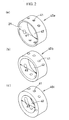
- Figs. 2 (a) to (c) are perspective views showing adjustment rings 40 to be fitted to the aperture 16 of the sensor base 15.
- the adjustment rings 40a, 40b and 40c are made of ceramic and are formed in a cylindrical shape, where the outer diameter of these rings is approximately the same as the inner diameter D of the aperture 16 of the sensor base 15, and through holes 42 formed at the center thereof function as an exhaust gas passage opening 21 through which exhaust gas pass when the sensor unit 11 is installed in the exhaust path.
- the width of the adjustment rings 40a, 40b, and 40c is formed to be the same as the thickness of the sensor base 15, and a plurality of laser-light passage small holes 41, 41 ... are formed in circumferential faces of the adjustment rings 40a, 40b and 40c to configure a laser-light passage portion.
- the laser light applied from the irradiation portion 25 passes through the laser-light passage small holes 41, 41... so as to be reflected a plurality of times between the reflecting mirrors 30 and 30, and then to be received by the detector 27 as a light-receiving portion.
- These laser-light passage small holes 41, 41... allow only the laser light reflected precisely by the reflecting mirrors 30 to pass therethrough, but block off the laser light deviating from the optical path, so that the measurement accuracy can be enhanced.
- the adjustment ring 40a of (a) is for big-size cars with an exhaust tube of a large inner diameter, where the thickness of the ring is formed small so as to allow the through hole 42 serving as the exhaust gas passage opening 21 to have a large inner diameter d1
- the adjustment ring 40c of (c) is for compact size cars with an exhaust tube of a small inner diameter, where the thickness of the ring is formed large so as to allow the through hole 42 serving as the exhaust gas passage opening 21 to have a small inner diameter d3
- the adjustment ring 40b of (b) is for medium-size cars, where the inner diameter d2 of the through hole 42 is formed to be a medium size between the adjustment ring 40a and the adjustment ring 40c.
- FIG. 2 illustrates three types of adjustment rings 40a, 40b and 40c, there is a need to prepare adjustment rings 40 with through holes 42 of different inner diameters in number corresponding to the number of types of inner diameters of the exhaust tubes as a target of the exhaust gas measurement.
- an adjustment ring 40 with an inner diameter that is the same as the inner diameter of the exhaust tube 4 of the vehicle as a target of the exhaust gas measurement is fitted to the aperture 16 of the sensor base 15, and a bolt 19 is threadably mounted on the bolt insertion hole 18 so as to fix and fit the adjustment ring 40 to the sensor base 15, thus configuring the sensor unit 11.
- Such a sensor unit 11 is disposed between a flange F of an exhaust tube 4 and a flange F of an exhaust tube 5 via gaskets, and the flanges F and F are coupled by bolts and nuts, whereby the sensor unit 11 is installed in the exhaust tubes 4 and 5.
- the irradiated laser light passes through the sensor hole 22, the laser-light passage small holes 41 of the adjustment ring 40 and the laser light passage slit 17 and is reflected by a reflecting mirror 30. After being reflected between the reflecting mirrors 30 and 30 a plurality of times, the laser light passes through the sensor hole 23 and is received by the detector 27 to be converted into an electrical signal.
- This electrical signal is input to the laser oscillation/light-receiving controller 6 via the signal line 28, and the laser oscillation/light-receiving controller 6 sends a differential signal between the intensity of the laser light emitted therefrom and the intensity of the received laser light to an analyzer (computer) 7.
- the analyzer 7 calculates an absorption spectrum absorbed by the exhaust gas based on the differential signal between the intensity of the laser light emitted and the intensity of the laser light received and analyzes this absorption spectrum, whereby the exhaust gas components contained in the exhaust gas and the concentrations thereof can be measured in real time.
- the irradiated laser light is reflected a plurality of times between the reflecting mirrors 30 and 30 opposed to each other and travels a long distance through the exhaust gas, during which the laser light at a specific wavelength is absorbed by an exhaust gas component in the exhaust gas in accordance with the traveling distance, and therefore even an exhaust gas component of a low concentration can be measured with accuracy.
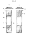
- Fig. 4 is for explaining heat conduction states of the exhaust gas in the sensor base 15 to which the adjustment ring 40 is fitted and the sensor base 55 to which the adjustment ring is not fitted, where the sensor unit 11 and the sensor unit 51 include exhaust gas passage openings 21 of the same inner diameter formed therein.
- the adjustment ring 40 is made of ceramic with good insulation effectiveness, which means less heat conduction in the adjustment ring 40, and therefore it can prevent an increase in temperature of the aperture 16 of the sensor base 15 due to the temperature of the exhaust gas. Therefore, as compared with one without the adjustment ring fitted thereto, an increase in temperature of the sensor base 15 is smaller, thus making it possible to reduce a temperature difference between the interior and the exterior of the sensor base 15.
- the distortion of the sensor base 15 due to heat of the exhaust gas flowing through the exhaust gas passage opening 21 can be suppressed, so that the displacement of the attachment positions of the reflecting mirrors 30 and the laser irradiation portion 25 can be made small, and thus the concentrations of the exhaust gas components in the exhaust gas can be measured stably. Further, since the sensor base 15 is not at a very high temperature even at the aperture 16, there is no need to form the sensor base with a heat-resisting material, and therefore the material of the sensor base can be selected from a wider range of materials.
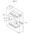
- Fig. 5 is a perspective view of a sensor unit to which an adjustment ring according to another embodiment of the present invention is fitted, where an aperture 16 of a sensor base 15 is formed to be rectangular.
- the outer shape of the adjustment ring 40 also is formed to be rectangular so as to be fitted to the aperture 16 of the sensor base, and the inner circumferential face is formed to be circular corresponding to the shape of the exhaust tube.
- the outer shape of the adjustment ring 40 other than a circular shape can eliminate the alignment of the sensor base 15 with the adjustment ring 40 that is for allowing the laser light applied from the irradiation portion to be reflected between the reflecting mirrors 30 and 30 and then to be received the detector 27.
- the present invention is not limited to the above-stated embodiments, and the design may be modified variously without departing from the spirits of the present invention defined in the attached claims.
- the laser light passage slit 17 for the laser light in the sensor base 15 is formed as an elongate hole.
- this may be a plurality of small holes.
- the laser-light passage small holes 41 of the adjustment ring 40 can be made a slit.
- the reflecting mirrors 30 and 30 are disposed to be opposed to each other across the aperture 16 of the sensor base 15.
- the sensor unit may include a sensor base without the reflecting mirrors 30 and 30 disposed therein, where the laser light applied from the irradiation portion traverses the exhaust gas passage opening while passing through the exhaust gas, and then is received by the light-receiving portion.
Landscapes
- Physics & Mathematics (AREA)
- Health & Medical Sciences (AREA)
- Life Sciences & Earth Sciences (AREA)
- Chemical & Material Sciences (AREA)
- Analytical Chemistry (AREA)
- Biochemistry (AREA)
- General Health & Medical Sciences (AREA)
- General Physics & Mathematics (AREA)
- Immunology (AREA)
- Pathology (AREA)
- Spectroscopy & Molecular Physics (AREA)
- Investigating Or Analysing Materials By Optical Means (AREA)
Abstract
Description
- The present invention relates to an exhaust gas analyzer installed in an exhaust path for an engine or the like, which is capable of measuring the concentration of an exhaust-gas component contained in exhaust gas flowing through the exhaust path, and more particularly relates to a sensor unit in an exhaust gas analyzer.
- Conventionally, a vehicle-mounted HC measurement device described in
JP Published Patent Application No. 2004-117259 A
Patent Document 1:JP Published Patent Application No. 2004-117259 A - Although the above-stated exhaust gas analyzer described in Patent Document 1 can facilitate measuring the THC in exhaust gas of a vehicle while the vehicle is moving on a real road, it is impossible to conduct the analysis of the exhaust gas in real time because the exhaust gas is transferred for the analysis of gas components from the exhaust path of the engine to the analysis section through a pipe. Further, in order to reduce the above-described units in size, analysis is carried out only to a limited component such as HC. At the development stage of an engine or attachments to the engine such as an exhaust gas purifier, it has been desired to provide an exhaust gas analyzer facilitating the measurement of components other than hydrocarbon in exhaust gas, such as nitrogen oxides and carbon monoxide, while being capable of measuring the concentration of the exhaust gas components in real time.
- Then, the applicant of the present invention has developed an exhaust gas analyzer capable of facilitating the measurement of even a large number of exhaust gas components in exhaust gas such as nitrogen oxides and carbon monoxide in real time. The exhaust gas analyzer, as shown in
Fig. 6 , is composed of a plurality ofsensor units 51A to 51D installed at a plurality of positions of an exhaust path of anexhaust tube 4 coupled to one ofexhaust pipes 3 of anengine 2, a laser oscillation/light-receivingcontroller 6 emitting laser light to be applied to the exhaust gas, while receiving an electrical signal as an input from a light-receiving portion that receives the laser light, and an analyzer (personal computer) 7 that analyzes components contained in the exhaust gas and the concentrations thereof based on the light-emission intensity of the laser light to be applied to the exhaust gas and the light-reception intensity of the received laser light that has passed through the exhaust gas. - Since the
sensor units 51 A to 51D of the exhaust gas analyzer have the same configuration, the following describes onesensor unit 51 with reference toFigs. 7 and8 . - The
sensor unit 51 is disposed between a flange portion F of theexhaust tube 4 and a flange portion F of anexhaust tube 5 via gaskets 9, and these flange portions F and F are coupled using bolts (not illustrated), so that thesensor unit 51 is installed in an exhaust path of the exhaust gas. - The
sensor unit 51 has a rectangularparallelepiped sensor base 55 made of metal. As shown in detail inFig. 8 , thesensor base 55 includes front andrear faces 55a and 55b orthogonal to the flowing direction of the exhaust gas, in which an exhaustgas passage opening 21 is formed at a center portion thereof, where the inner diameter of the exhaust gas passage opening 21 is the same as the inner diameter d of the circular cross section of theexhaust tube 4 so as not to disturb the flow of the exhaust gas. On anupper side face 55c perpendicular to the front andrear faces 55a and 55b, asensor hole 22 is formed at a left part thereof to be orthogonal to the flowing direction of the exhaust gas, where thesensor hole 22 penetrates through the center of the wall thickness to the exhaust gas passage opening 21. On alower side face 55d, asensor hole 23 is formed at a right part thereof to be orthogonal to the flowing direction of the exhaust gas, where thesensor hole 23 penetrates through the center of the wall thickness from the edge to the exhaust gas passage opening 21. - To the
sensor hole 22 of thesensor base 55, anirradiation portion 25 is attached, through which laser light is applied. Theirradiation portion 25 is configured so as to be coupled to the laser oscillation/light-receivingcontroller 6 via anoptical fiber 26, thus allowing laser light emitted from the laser oscillation/light-receivingcontroller 6 to be applied to the exhaust gas from theirradiation portion 25 via a collimate lens. To thesensor hole 23, adetector 27 is attached as a light-receiving portion that receives laser light applied from theirradiation portion 25 toward the exhaust gas passage opening 21 and that has passed through the exhaust gas. Thedetector 27 is coupled to the laser oscillation/light-receivingcontroller 6 via asignal line 28. - The
sensor base 55 includes reflectingmirror insertion grooves mirror insertion grooves screw holes 38 with female thread formed on the inner circumferential faces are bored so as to penetrate through to the exhaust gas passage opening 21. Reflectingmirrors mirror insertion grooves mirrors 30 are fixed thereto byscrews 39 threadably mounted on thescrew holes 38 from the exhaust gas passage opening 21. - Each reflecting
mirror 30 includes a rectangular substrate made of quartz, sapphire, ceramic or the like with a thickness of several millimeters, on one side of which a thin film made of a reflective material with a high reflectivity such as gold, platinum, or titanium oxide matching with a laser wavelength is coated, on which a thin film of MgF2 or SiO2 is formed as a protective layer, thus configuring a reflecting surface. - Between the reflecting
mirror insertion grooves light passage holes 56 with a small diameter are formed, so that the laser light applied from theirradiation portion 25 into thesensor hole 22 is reflected a plurality of times between the reflectingmirrors sensor hole 23. - The
sensor base 55 further includes a right-side face 55e in which aheater insertion opening 33 is formed above and parallel to the reflectingmirror insertion groove 31, and includes a left-side face 55f in which aheater insertion opening 34 is formed below and parallel to the reflectingmirror insertion groove 32. Into theseheater insertion openings condensation prevention heaters 35 are inserted, which are fixed thereto byscrews 37 threadably mounted onscrew holes 36. The dew-condensation prevention heaters 35 heat the reflectingmirrors mirrors - Then, in the exhaust gas analyzer shown in
Figs. 6 to 8 , the laser light emitted from the laser oscillation/light-receivingcontroller 6 is applied to the exhaust gas from theirradiation portion 25 via theoptical fiber 26, and the applied laser light is reflected a plurality of times between the reflectingmirrors detector 27 after traveling a long distance through the exhaust gas, so as to be converted into an electrical signal. This electrical signal is input to the laser oscillation/light-receiving controller 6, and the laser oscillation/light-receiving controller 6 sends, to theanalyzer 7, a differential signal between the intensity of the laser light emitted therefrom and the intensity of the received laser light. - The
analyzer 7 calculates an absorption spectrum absorbed by the exhaust gas based on the differential signal transmitted from the laser oscillation/light-receivingcontroller 6 and analyzes this absorption spectrum, so that the exhaust gas components contained in the exhaust gas and the concentrations thereof can be measured in real time. - In the exhaust gas analyzer of
Figs. 6 to 8 , thesensor units 51 are installed in theexhaust tubes exhaust tube 4, thus measuring the components and the concentrations of the exhaust gas in the same state as the exhaust gas flowing through the exhaust tube when the vehicle is actually moving. If the inner diameter of theexhaust tubes sensor unit 51, then the flow of the exhaust gas will be disturbed, and the state of the flow will be different from the exhaust gas flowing through the exhaust tube when the vehicle is actually moving. Therefore, in order to measure the exhaust gas in the same state as the exhaust gas flowing through the exhaust tube when the vehicle is actually moving, the inner diameter of the exhaust gas passage opening 21 of thesensor unit 51 has to be the same as the inner diameter d of the exhaust tubes. - Meanwhile, currently there are a large number of types of cars including big-size cars, standard-sized cars, compact cars and the like available, and their exhaust tubes have different inner diameters depending on the car types. Furthermore, the inner diameters of the exhaust tubes will be different depending on the positions of the exhaust path, and therefore a large number of types of
sensor units 51 having exhaustgas passage openings 21 with different inner diameters have to be prepared in order to enable the measurement of the exhaust gas at a plurality of positions of the exhaust path of these vehicles when the vehicles are moving. For example, for fifteen types of cars, each of which has three exhaust-tube connection positions on average, forty-five types of sensor units have to be prepared, which means expensive manufacturing cost. - Further, the exhaust gas flowing inside the exhaust tube will be at a high temperature as high as 1,000°C in the
exhaust tube 4 in the upstream closer to theengine 2, and will be at about 100°C even at a low temperature section in the downstream. This means that the temperature of thesensor base 55 of thesensor units 51 A to 51D will change in the range from about 20°C as an ambient temperature to about 1,000°C depending on the installation position. Thus, thesensor base 55 expands and shrinks repeatedly as the temperature changes, causing the displacement of theirradiation portion 25 and the reflectingmirrors 30 thereof, and the reflectingmirrors 30 may fail to reflect the laser light in correct directions, so that the laser light applied from theirradiation portion 25 may fail to arrive at thedetector 27, resulting in a failure of the measurement. - Moreover, since the exhaust gas at a high temperature directly contacts with the exhaust gas passage opening 21 of the
sensor base 55, the surface thereof may be damaged, and in that case thesensor base 55 as a whole has to be replaced even through other parts of thesensor base 55 still can be used. - In view of the above-stated problems, it is an object of the invention to provide a sensor unit in an exhaust gas analyzer at a low cost, the sensor unit being attachable to exhaust tubes so as to conform to their different inner diameters, and capable of stably measuring the concentration of exhaust gas components in exhaust gas when the vehicle is actually moving.
- In order to fulfill the above-stated object, a sensor unit in an exhaust gas analyzer of the present invention is installed in an exhaust path of exhaust gas and includes a sensor base including an exhaust gas passage opening through which exhaust gas passes, an irradiation portion from which laser light is applied and a light receiving portion, the irradiation portion and the light receiving portion being provided at the sensor base. Laser light applied from the irradiation portion to exhaust gas in the exhaust gas passage opening is received by the light receiving portion and a concentration of a component contained in the exhaust gas is measured based on the received laser light. The exhaust gas passage opening includes a through hole through which exhaust gas passes formed in an adjustment ring detachably fitted to an aperture formed in the sensor base, and the adjustment ring includes a circumferential face in which a laser-light passage portion is formed for allowing the laser light applied from the irradiation portion to arrive at the light receiving portion.
- According to the sensor unit in an exhaust gas analyzer of the present invention, the laser light applied from the irradiation portion passes through the laser light passage portion in the circumferential face of the adjustment ring, passes through the exhaust gas, and is received by the light receiving portion, and the exhaust gas analyzer can measure the concentration of a component contained in the exhaust gas based on the received laser light. In the case where the through hole of the adjustment ring is damaged by the exhaust gas at a high temperature flowing through the through hole of the adjustment ring, the adjustment ring may be replaced with another one, whereby the sensor unit can be reused.
- Further, the sensor base of the sensor unit according to the present invention includes reflecting mirrors disposed to be opposed to each other across the aperture, and the adjustment ring includes a circumferential face in which a laser-light passage portion is formed for letting the laser light reflected by the reflecting mirrors pass therethrough.
- According to the sensor base of the sensor unit according to the present invention, the irradiated laser light passes through the laser light passage portion in the circumferential face of the adjustment ring, is reflected a plurality of times between the reflecting mirrors and travels a long distance through the exhaust gas, during which the laser light at a specific wavelength is absorbed by an exhaust gas component in the exhaust gas in accordance with the traveling distance, and therefore even an exhaust gas component of a low concentration can be measured for the concentration with accuracy.
- The adjustment ring of the sensor unit according to the present invention is replaceable for fitting with an adjustment ring with a same outer shape and including a through hole with a different inner diameter. Further, in the sensor unit in an exhaust gas analyzer of the present invention, the adjustment ring is replaceable for fitting with a cylindrical adjustment ring with a same outer diameter and including a through hole with a different inner diameter.
- In the adjustment ring of the sensor unit according to of the present invention, an adjustment ring with an inner diameter that is the same as the inner diameter of the exhaust tube is fitted to the aperture of the sensor base for replacement, whereby a sensor unit compatible with various inner diameters of exhaust tubes can be configured using one type of sensor base. The outer shape of the adjustment ring according to the present invention may be any shape as long as it has the same shape as the aperture of the sensor base. A circular shape can facilitate the manufacturing thereof, and an outer shape other than a circular shape can eliminate the necessity of the alignment of the laser light passage portion formed in the circumferential face of the adjustment ring when the adjustment ring is fitted to the aperture of the sensor base.
- In the adjustment ring of the sensor unit according to the present invention, the laser-light passage portion formed in the circumferential face of the adjustment ring includes a plurality of small holes. In the adjustment ring of the sensor unit according to the present invention, when noise light occurs because the laser light applied into the exhaust gas passage opening is reflected by a dirt on the reflecting mirror, for example, such noise light is blocked off by a portion where the small holes are not formed, and the laser light for measurement only is allowed to pass through the small holes for laser-light passage, is reflected by the reflecting mirrors, and is received by the light receiving portion, whereby the concentration of an exhaust gas component in the exhaust gas can be measured with accuracy.
- The adjustment ring of the sensor unit according to the present invention is made of a heat-insulating material. Further, the adjustment ring of the sensor unit according to the present invention is made of ceramic. According to the adjustment ring of the sensor unit of the present invention, heat at a high temperature from the exhaust gas flowing through the exhaust gas passage opening is blocked off by the adjustment ring made of ceramic with a heat insulation property, so that the heat at a high temperature from the exhaust gas is not conducted so much to the sensor base. Therefore, the distortion of the sensor base due to heat can be suppressed, so that the attachment positions of the reflecting mirrors, the irradiation portion and the light receiving portion are not displaced, and thus the concentrations of the exhaust gas components in the exhaust gas can be measured stably. Further, since the sensor base is not at a high temperature, there is no need to form the sensor base with a heat-resisting material, and therefore the material of the sensor base can be selected from a wider range of materials.
- In the sensor unit in an exhaust gas analyzer of the present invention, the adjustment ring with a through hole formed therein for letting exhaust gas pass therethrough is detachably fitted to the aperture formed in the sensor base, and in the circumferential face of the adjustment ring, the laser light passage portion is formed for allowing the laser light applied from the irradiation portion to arrive at the light receiving portion. Therefore, if the through hole of the adjustment ring is damaged due to a temperature of the exhaust gas or the like, the adjustment ring may be replaced with another one, whereby the sensor unit can be reused. Further, the adjustment ring is replaced for fitting with an adjustment ring with a through hole having a different inner diameter, whereby a sensor unit with exhaust gas passage openings of different inner diameters can be composed using one type of sensor base, which can be installed in exhaust tubes with various inner diameters.
-
-
Fig. 1 illustrates a sensor base in a sensor unit according to one embodiment of the present invention, where (a) is a front view of the sensor base, (b) is a cross-sectional view taken along the line A-A of (a), and (c) is a cross-sectional view taken along the line B-B of (a). -
Fig. 2 is a perspective view of an adjustment ring in a sensor unit according to one embodiment of the present invention. -
Fig. 3 is a perspective view of a sensor unit according to one embodiment of the present invention. -
Fig. 4 is for explaining heat conduction states of exhaust gas in a sensor unit according to one embodiment of the present invention and in a sensor unit without the adjustment ring fitted thereto, where (a) shows one with an adjustment ring, and (b) shows one without an adjustment ring. -
Fig. 5 is a perspective view of a sensor unit to which an adjustment ring according to another embodiment of the present invention is fitted. -
Fig. 6 shows the configuration of major parts showing a state where an exhaust gas analyzer invented by the applicant of the present invention is mounted in a vehicle. -
Fig. 7 is a perspective view of a state where the sensor unit of the exhaust gas analyzer is removed from an exhaust tube. -
Fig. 8 shows the sensor unit of the exhaust gas analyzer, where (a) is a front view of the sensor unit, (b) is a cross-sectional view taken along the line A-A of (a), and (c) is a cross-sectional view taken along the line B-B of (a). - In these drawings, the respective reference numbers denote the followings:
- 2
- engine
- 3
- each exhaust pipe
- 4
- exhaust tube
- 5
- exhaust tube
- 6
- laser oscillation/light-receiving controller
- 7
- computer
- 11
- sensor unit
- 15
- sensor base
- 16
- aperture
- 17
- laser light passage slit
- 18
- bolt insertion hole
- 19
- bolt
- 21
- exhaust gas passage opening
- 22
- sensor hole
- 23
- sensor hole
- 25
- irradiation portion
- 26
- optical fiber
- 27
- detector
- 28
- signal line
- 30
- reflecting mirror
- 31, 32
- reflecting mirror insertion groove
- 33, 34
- heater insertion opening
- 35
- dew-condensation prevention heater
- 36
- screw hole
- 37
- screw
- 38
- screw hole
- 39
- screw
- 40, 40a, 40b, 40c
- adjustment ring
- 41
- laser-light passage small hole.
-
Fig. 1 illustrates a sensor base in a sensor unit according to Embodiment 1 for implementing the present invention, where (a) is a front view of the sensor base, (b) is a cross-sectional view taken along the line A-A of (a), and (c) is a cross-sectional view taken along the line B-B of (a). The same reference numerals have been assigned to the elements with the same configurations as those in the sensor unit ofFigs. 6 to 8 . - As shown in
Fig. 1 , asensor base 15 of asensor unit 11 of the present invention is made of metal and has a rectangular parallelepiped shape. Thesensor base 15 includes front andrear faces diameter aperture 16 with a diameter D is formed at a center portion thereof. On anupper side face 15c perpendicular to the front andrear faces sensor hole 22 is formed at a left part thereof to be orthogonal to the flowing direction of the exhaust gas, where thesensor hole 22 penetrates through the center of the wall thickness to theaperture 16. On alower side face 15d, asensor hole 23 is formed on a right part thereof to be orthogonal to the flowing direction of the exhaust gas, where thesensor hole 23 penetrates through the center of the wall thickness to theaperture 16. The diameter D of theaperture 16 has to be made larger than the inner diameter d of an exhaust tube of a vehicle as a target of the measurement of exhaust gas by thesensor unit 11. - To the
sensor hole 22 of thesensor base 15, anirradiation portion 25 is attached, through which laser light is applied. Theirradiation portion 25 is configured so as to be coupled to a laser oscillation/light-receivingcontroller 6 via anoptical fiber 26, thus allowing laser light emitted from the laser oscillation/light-receivingcontroller 6 to be applied to the exhaust gas from theirradiation portion 25 via a collimate lens. To thesensor hole 23, adetector 27 is attached as a light-receiving portion that receives laser light applied from theirradiation portion 25 toward the exhaust gas passage opening 21 and that has passed through the exhaust gas, where thedetector 27 is coupled to the laser oscillation/light-receivingcontroller 6 via asignal line 28. - The front and
rear faces sensor base 15 include reflectingmirror insertion grooves aperture 16. At right and left of each of the reflectingmirror insertion grooves aperture 16. Reflecting mirrors 30 and 30 are inserted into the reflectingmirror insertion grooves aperture 16, and the reflecting mirrors 30 are fixed thereto by screws threadably mounted on the screw holes 38 from theaperture 16. - Each reflecting
mirror 30 includes a rectangular substrate made of quartz, sapphire, ceramic or the like with a thickness of several millimeters, on one side of which a thin film made of a reflective material with a high reflectivity such as gold, platinum, or titanium oxide matching with a laser wavelength is coated, on which a thin film of MgF2 or SiO2 is formed as a protective layer so as to configure a reflecting surface. - Between the reflecting
mirror insertion grooves aperture 16, a long and narrow laser light passage slit 17 is formed, so that the laser light can be reflected a plurality of times between the reflecting mirrors 30 and 30. - The
sensor base 15 further includes a right-side face 15e in which aheater insertion opening 33 is formed above and parallel to the reflectingmirror insertion groove 31, and includes a left-side face 15f in which aheater insertion opening 34 is formed below and parallel to the reflectingmirror insertion groove 32. Into theseheater insertion openings condensation prevention heaters 35 are inserted, which are fixed thereto byscrews 37 threadably mounted on screw holes 36. The dew-condensation prevention heaters 35 heat the reflecting mirrors 30 and 30 so as to prevent the condensation on the reflecting surfaces of the reflecting mirrors 30 and 30. - At the right-
side face 15e of thesensor base 15, abolt insertion hole 18 with a female thread formed on the inner surface is formed so as to penetrate through to theaperture 16. -
Figs. 2 (a) to (c) are perspective views showing adjustment rings 40 to be fitted to theaperture 16 of thesensor base 15. The adjustment rings 40a, 40b and 40c are made of ceramic and are formed in a cylindrical shape, where the outer diameter of these rings is approximately the same as the inner diameter D of theaperture 16 of thesensor base 15, and throughholes 42 formed at the center thereof function as an exhaust gas passage opening 21 through which exhaust gas pass when thesensor unit 11 is installed in the exhaust path. - The width of the adjustment rings 40a, 40b, and 40c is formed to be the same as the thickness of the
sensor base 15, and a plurality of laser-light passagesmall holes irradiation portion 25 passes through the laser-light passagesmall holes detector 27 as a light-receiving portion. These laser-light passagesmall holes - In
Fig. 2 , theadjustment ring 40a of (a) is for big-size cars with an exhaust tube of a large inner diameter, where the thickness of the ring is formed small so as to allow the throughhole 42 serving as the exhaust gas passage opening 21 to have a large inner diameter d1, theadjustment ring 40c of (c) is for compact size cars with an exhaust tube of a small inner diameter, where the thickness of the ring is formed large so as to allow the throughhole 42 serving as the exhaust gas passage opening 21 to have a small inner diameter d3, and theadjustment ring 40b of (b) is for medium-size cars, where the inner diameter d2 of the throughhole 42 is formed to be a medium size between theadjustment ring 40a and theadjustment ring 40c. - Although
Fig. 2 illustrates three types of adjustment rings 40a, 40b and 40c, there is a need to prepare adjustment rings 40 with throughholes 42 of different inner diameters in number corresponding to the number of types of inner diameters of the exhaust tubes as a target of the exhaust gas measurement. - Then, as shown in
Fig. 3 , anadjustment ring 40 with an inner diameter that is the same as the inner diameter of theexhaust tube 4 of the vehicle as a target of the exhaust gas measurement is fitted to theaperture 16 of thesensor base 15, and abolt 19 is threadably mounted on thebolt insertion hole 18 so as to fix and fit theadjustment ring 40 to thesensor base 15, thus configuring thesensor unit 11. - Such a
sensor unit 11 is disposed between a flange F of anexhaust tube 4 and a flange F of anexhaust tube 5 via gaskets, and the flanges F and F are coupled by bolts and nuts, whereby thesensor unit 11 is installed in theexhaust tubes - Then, when the exhaust gas flowing through the exhaust gas passage opening 21 is irradiated with the laser light from the
irradiation portion 25, the irradiated laser light passes through thesensor hole 22, the laser-light passagesmall holes 41 of theadjustment ring 40 and the laser light passage slit 17 and is reflected by a reflectingmirror 30. After being reflected between the reflecting mirrors 30 and 30 a plurality of times, the laser light passes through thesensor hole 23 and is received by thedetector 27 to be converted into an electrical signal. This electrical signal is input to the laser oscillation/light-receivingcontroller 6 via thesignal line 28, and the laser oscillation/light-receivingcontroller 6 sends a differential signal between the intensity of the laser light emitted therefrom and the intensity of the received laser light to an analyzer (computer) 7. Theanalyzer 7 calculates an absorption spectrum absorbed by the exhaust gas based on the differential signal between the intensity of the laser light emitted and the intensity of the laser light received and analyzes this absorption spectrum, whereby the exhaust gas components contained in the exhaust gas and the concentrations thereof can be measured in real time. - The irradiated laser light is reflected a plurality of times between the reflecting mirrors 30 and 30 opposed to each other and travels a long distance through the exhaust gas, during which the laser light at a specific wavelength is absorbed by an exhaust gas component in the exhaust gas in accordance with the traveling distance, and therefore even an exhaust gas component of a low concentration can be measured with accuracy.
-
Fig. 4 is for explaining heat conduction states of the exhaust gas in thesensor base 15 to which theadjustment ring 40 is fitted and thesensor base 55 to which the adjustment ring is not fitted, where thesensor unit 11 and thesensor unit 51 include exhaustgas passage openings 21 of the same inner diameter formed therein. - In the
sensor base 15 with theadjustment ring 40 fitted thereto, theadjustment ring 40 is made of ceramic with good insulation effectiveness, which means less heat conduction in theadjustment ring 40, and therefore it can prevent an increase in temperature of theaperture 16 of thesensor base 15 due to the temperature of the exhaust gas. Therefore, as compared with one without the adjustment ring fitted thereto, an increase in temperature of thesensor base 15 is smaller, thus making it possible to reduce a temperature difference between the interior and the exterior of thesensor base 15. Since the distortion of thesensor base 15 due to heat of the exhaust gas flowing through the exhaust gas passage opening 21 can be suppressed, so that the displacement of the attachment positions of the reflecting mirrors 30 and thelaser irradiation portion 25 can be made small, and thus the concentrations of the exhaust gas components in the exhaust gas can be measured stably. Further, since thesensor base 15 is not at a very high temperature even at theaperture 16, there is no need to form the sensor base with a heat-resisting material, and therefore the material of the sensor base can be selected from a wider range of materials. -
Fig. 5 is a perspective view of a sensor unit to which an adjustment ring according to another embodiment of the present invention is fitted, where anaperture 16 of asensor base 15 is formed to be rectangular. The outer shape of theadjustment ring 40 also is formed to be rectangular so as to be fitted to theaperture 16 of the sensor base, and the inner circumferential face is formed to be circular corresponding to the shape of the exhaust tube. The outer shape of theadjustment ring 40 other than a circular shape can eliminate the alignment of thesensor base 15 with theadjustment ring 40 that is for allowing the laser light applied from the irradiation portion to be reflected between the reflecting mirrors 30 and 30 and then to be received thedetector 27. - Although that is a detailed description of the embodiments of the present invention, the present invention is not limited to the above-stated embodiments, and the design may be modified variously without departing from the spirits of the present invention defined in the attached claims. For instance, in the above embodiment, the laser light passage slit 17 for the laser light in the
sensor base 15 is formed as an elongate hole. However, as shown inFig. 8 , this may be a plurality of small holes. In this case, the laser-light passagesmall holes 41 of theadjustment ring 40 can be made a slit. Furthermore, in the sensor unit of the above-described embodiments, the reflecting mirrors 30 and 30 are disposed to be opposed to each other across theaperture 16 of thesensor base 15. However, the sensor unit may include a sensor base without the reflecting mirrors 30 and 30 disposed therein, where the laser light applied from the irradiation portion traverses the exhaust gas passage opening while passing through the exhaust gas, and then is received by the light-receiving portion.
Claims (7)
- A sensor unit in an exhaust gas analyzer, the sensor unit being installed in an exhaust path of exhaust gas and comprising a sensor base including an exhaust gas passage opening through which exhaust gas passes, an irradiation portion from which laser light is applied and a light receiving portion, the irradiation portion and the light receiving portion being provided at the sensor base, wherein laser light applied from the irradiation portion to exhaust gas in the exhaust gas passage opening is received by the light receiving portion and a concentration of a component contained in the exhaust gas is measured based on the received laser light,
wherein the exhaust gas passage opening comprises a through hole through which exhaust gas passes formed in an adjustment ring detachably fitted to an aperture formed in the sensor base, and
wherein the adjustment ring includes a circumferential face in which a laser-light passage portion is formed for allowing laser light applied from the irradiation portion to arrive at the light receiving portion. - The sensor unit in an exhaust gas analyzer according to claim 1, wherein the sensor base includes reflecting mirrors disposed to be opposed to each other across the aperture, and the adjustment ring includes a circumferential face in which a laser-light passage portion is formed for letting laser light reflected by the reflecting mirrors pass therethrough.
- The sensor unit in an exhaust gas analyzer according to claim 1 or 2, wherein the adjustment ring is replaceable with an adjustment ring with a same outer shape and including the through hole with a different inner diameter.
- The sensor unit in an exhaust gas analyzer according to claim 1 or 2, wherein the adjustment ring is replaceable with a cylindrical adjustment ring with a same outer diameter and including a through hole with a different inner diameter.
- The sensor unit in an exhaust gas analyzer according to any one of claims 1 to 4, wherein the laser-light passage portion formed in the circumferential face of the adjustment ring includes a plurality of small holes.
- The sensor unit in an exhaust gas analyzer according to any one of claims 1 to 5, wherein the adjustment ring is made of a heat-insulating material.
- The sensor unit in an exhaust gas analyzer according to any one of claims 1 to 6, wherein the adjustment ring is made of ceramic.
Applications Claiming Priority (2)
| Application Number | Priority Date | Filing Date | Title |
|---|---|---|---|
| JP2006151536A JP4594277B2 (en) | 2006-05-31 | 2006-05-31 | Sensor unit in exhaust gas analyzer |
| PCT/JP2007/061245 WO2007139223A1 (en) | 2006-05-31 | 2007-05-29 | Sensor unit of exhaust gas analyzer |
Publications (3)
| Publication Number | Publication Date |
|---|---|
| EP1998164A1 true EP1998164A1 (en) | 2008-12-03 |
| EP1998164A4 EP1998164A4 (en) | 2009-03-11 |
| EP1998164B1 EP1998164B1 (en) | 2010-09-29 |
Family
ID=38778735
Family Applications (1)
| Application Number | Title | Priority Date | Filing Date |
|---|---|---|---|
| EP20070744631 Ceased EP1998164B1 (en) | 2006-05-31 | 2007-05-29 | Exhaust gas analyzer comprising a sensor unit |
Country Status (7)
| Country | Link |
|---|---|
| US (1) | US7936460B2 (en) |
| EP (1) | EP1998164B1 (en) |
| JP (1) | JP4594277B2 (en) |
| KR (1) | KR101018613B1 (en) |
| CN (1) | CN101400989B (en) |
| DE (1) | DE602007009499D1 (en) |
| WO (1) | WO2007139223A1 (en) |
Cited By (1)
| Publication number | Priority date | Publication date | Assignee | Title |
|---|---|---|---|---|
| WO2016203233A1 (en) * | 2015-06-16 | 2016-12-22 | Gassecure As | Optical elements in gas sensors |
Families Citing this family (17)
| Publication number | Priority date | Publication date | Assignee | Title |
|---|---|---|---|---|
| US8208143B2 (en) * | 2005-04-28 | 2012-06-26 | Toyota Jidosha Kabushiki Kaisha | Exhaust gas analyzer |
| JP4227991B2 (en) * | 2005-12-28 | 2009-02-18 | トヨタ自動車株式会社 | Exhaust gas analyzer and exhaust gas analysis method |
| EP1887343A1 (en) * | 2006-08-11 | 2008-02-13 | Geoservices | Device for quantifying the content of at least one gaseous constituent contained in a gaseous sample from a fluid, related assembly and process |
| JP4732277B2 (en) * | 2006-08-23 | 2011-07-27 | トヨタ自動車株式会社 | Gas analyzer and gas analysis method |
| US8424292B2 (en) * | 2009-12-31 | 2013-04-23 | General Electric Company | Systems and apparatus relating to the monitoring and/or controlling of selective catalytic reduction processes |
| US8158946B2 (en) * | 2010-08-25 | 2012-04-17 | Airware, Inc. | Intrinsically safe improved sensitivity NDIR gas sensor in a can |
| US8003945B1 (en) * | 2010-08-25 | 2011-08-23 | Jacob Y Wong | Intrinsically safe NDIR gas sensor in a can |
| US8616006B2 (en) * | 2010-11-30 | 2013-12-31 | General Electric Company | Advanced optics and optical access for laser ignition for gas turbines including aircraft engines |
| JP5815377B2 (en) * | 2010-12-27 | 2015-11-17 | 株式会社堀場製作所 | Gas concentration measuring device |
| JP2014115194A (en) * | 2012-12-10 | 2014-06-26 | Mitsubishi Heavy Ind Ltd | Pipe for gas measurement, and method of manufacturing the same |
| US10324028B2 (en) * | 2014-08-29 | 2019-06-18 | Tohoku University | Optical concentration measuring method |
| JP6450850B2 (en) * | 2015-01-19 | 2019-01-09 | インテグリス・インコーポレーテッド | Small volume, long path length multi-pass gas cell for monitoring infrared and ultraviolet radiation |
| EP3563138B1 (en) * | 2016-12-27 | 2022-08-17 | GE Infrastructure Sensing, LLC | Portable moisture analyzer for natural gas |
| EP3911938B1 (en) * | 2019-01-16 | 2024-05-29 | Indrio Technologies, Inc. | Laser-based in-situ exhaust gas sensor |
| KR102924943B1 (en) * | 2020-12-02 | 2026-02-09 | 에스케이온 주식회사 | Battery pack having gas discharging unit |
| CN114577985A (en) * | 2022-02-11 | 2022-06-03 | 深圳市卡普瑞环境科技有限公司 | Thermostatic module of small-sized gas sensing device and small-sized gas sensing device |
| CN118914133B (en) * | 2024-10-09 | 2025-01-10 | 沈阳格沃德环保科技有限公司 | Self-adaptive flue gas detection device |
Family Cites Families (68)
| Publication number | Priority date | Publication date | Assignee | Title |
|---|---|---|---|---|
| US3207026A (en) | 1960-03-01 | 1965-09-21 | Graviner Manufacturing Co | Apparatus and method for determining the individual and average content of light absorbing fluids |
| US3958122A (en) | 1974-12-19 | 1976-05-18 | United Technologies Corporation | Exhaust gas analyzer having pressure and temperature compensation |
| CH642473A5 (en) | 1978-12-19 | 1984-04-13 | Cerberus Ag | Smoke detector |
| DE3022114C2 (en) | 1980-06-12 | 1983-05-26 | Erwin Sick Gmbh Optik-Elektronik, 7808 Waldkirch | Device for measuring the optical transmission or absorption capacity of a light-permeable material |
| JPH07115892B2 (en) | 1986-10-23 | 1995-12-13 | 古河電気工業株式会社 | UV curable resin composition for optical fiber |
| JPS63107845U (en) * | 1987-01-05 | 1988-07-12 | ||
| SE8802536D0 (en) * | 1988-07-07 | 1988-07-07 | Altoptronic Ab | METHOD AND APPARATUS FOR SPECTROSCOPIC MEASUREMENT OF THE CONCENTRATION OF A GAS IN A SAMPLE |
| US5096834A (en) | 1988-09-30 | 1992-03-17 | Agency Of Industrial Science And Technology | Method for determination of concentration of smoke and apparatus therefor |
| US4953978A (en) | 1989-03-03 | 1990-09-04 | Coulter Electronics Of New England, Inc. | Particle size analysis utilizing polarization intensity differential scattering |
| JP2837442B2 (en) | 1989-06-21 | 1998-12-16 | マツダ株式会社 | Engine oil deterioration detection method |
| JPH0325352A (en) | 1989-06-23 | 1991-02-04 | Hitachi Ltd | Flame tomographic measuring method |
| JPH0331726A (en) | 1989-06-29 | 1991-02-12 | Shimadzu Corp | Light source compensating mechanism for spectroscope |
| US5060505A (en) | 1989-09-12 | 1991-10-29 | Sensors, Inc. | Non-dispersive infrared gas analyzer system |
| JPH0416749A (en) | 1990-05-11 | 1992-01-21 | Japan Steel Works Ltd:The | Method and apparatus for measuring ozone concentration |
| JPH0427846A (en) * | 1990-05-24 | 1992-01-30 | Nippondenso Co Ltd | Measuring apparatus for concentration of fine particle |
| US5112215A (en) | 1991-06-20 | 1992-05-12 | Physical Sciences, Inc. | Apparatus for combustion, pollution and chemical process control |
| JP2744742B2 (en) | 1992-11-05 | 1998-04-28 | 東京電力株式会社 | Gas concentration measuring method and its measuring device |
| US5448071A (en) | 1993-04-16 | 1995-09-05 | Bruce W. McCaul | Gas spectroscopy |
| JP3246209B2 (en) | 1994-08-10 | 2002-01-15 | 富士電機株式会社 | Method and apparatus for measuring chromaticity and turbidity of solvent containing colloidal substance |
| US5572031A (en) | 1994-11-23 | 1996-11-05 | Sri International | Pressure- and temperature-compensating oxygen sensor |
| JPH08278179A (en) * | 1995-04-05 | 1996-10-22 | Hitachi Ltd | Heat resistance type air flow rate measuring device |
| JP3450938B2 (en) | 1995-06-12 | 2003-09-29 | 東京電力株式会社 | Gas concentration measuring method and apparatus |
| US5963336A (en) | 1995-10-10 | 1999-10-05 | American Air Liquide Inc. | Chamber effluent monitoring system and semiconductor processing system comprising absorption spectroscopy measurement system, and methods of use |
| US5818578A (en) | 1995-10-10 | 1998-10-06 | American Air Liquide Inc. | Polygonal planar multipass cell, system and apparatus including same, and method of use |
| DE69712053T2 (en) | 1996-05-14 | 2002-11-14 | Honeywell International Inc., Morristown | OPTICAL SENSOR TO ENVIRONMENTAL INFLUENCES WITH IMPROVED NOISE REDUCTION |
| JPH105A (en) | 1996-06-17 | 1998-01-06 | Iseki & Co Ltd | Orthopedics |
| RU2180107C2 (en) * | 1997-08-25 | 2002-02-27 | Виссеншафтлихе Веркштатт Фюр Умвельтместехник Гмбх | Automobile exhaust-gas analyzer |
| JPH1183734A (en) | 1997-09-05 | 1999-03-26 | Mitsubishi Heavy Ind Ltd | Gas detector and gas detecting method |
| US6107631A (en) | 1998-03-13 | 2000-08-22 | Alliedsignal Inc. | Self-calibration approach for tunable laser spectral absorption sensors |
| JPH11325427A (en) | 1998-05-19 | 1999-11-26 | Mitsubishi Heavy Ind Ltd | Combustion control method in combustion furnace and the combustion furnace |
| JP4038631B2 (en) | 1998-08-28 | 2008-01-30 | 株式会社堀場製作所 | High-speed measurement method and system for temperature, concentration, and chemical species using semiconductor laser spectroscopy |
| JP2000206041A (en) | 1999-01-19 | 2000-07-28 | Japan Radio Co Ltd | Method for detecting the concentration of inclusions in a sample using laser spectroscopy |
| DE19904691C2 (en) * | 1999-02-05 | 2003-05-28 | Esytec En U Systemtechnik Gmbh | Device and method for the simultaneous in-situ determination of the particle size and mass concentration of fluid-borne particles |
| JP2000283915A (en) | 1999-03-31 | 2000-10-13 | Tokyo Gas Co Ltd | How to compensate for other gas effects in gas measurement |
| JP2000314345A (en) | 1999-04-30 | 2000-11-14 | Nissan Motor Co Ltd | Laser type physical quantity measurement device for engines |
| JP3342446B2 (en) | 1999-08-31 | 2002-11-11 | 三菱重工業株式会社 | Gas concentration measurement device |
| JP2001124674A (en) | 1999-10-25 | 2001-05-11 | Horiba Ltd | On-vehicle engine exhaust gas analyzer |
| JP2001174410A (en) | 1999-12-21 | 2001-06-29 | Nkk Corp | Lighting equipment |
| JP2002048711A (en) | 2000-08-03 | 2002-02-15 | Mitsubishi Heavy Ind Ltd | Laser measuring device |
| JP3572274B2 (en) | 2000-08-17 | 2004-09-29 | 三菱重工業株式会社 | Exhaust gas pretreatment device and method |
| US6542831B1 (en) | 2001-04-18 | 2003-04-01 | Desert Research Institute | Vehicle particulate sensor system |
| DE10124235B4 (en) | 2001-05-18 | 2004-08-12 | Esytec Energie- Und Systemtechnik Gmbh | Method and device for the comprehensive characterization and control of the exhaust gas and the control of engines, especially internal combustion engines, and of components of the exhaust gas aftertreatment |
| JP3622696B2 (en) | 2001-07-17 | 2005-02-23 | 株式会社島津製作所 | Method and apparatus for measuring suspended particulate matter |
| JP3851531B2 (en) * | 2001-10-03 | 2006-11-29 | 株式会社堀場製作所 | Particulate matter measuring apparatus and method |
| DE10150970A1 (en) * | 2001-10-10 | 2003-04-17 | Matthias Lau | Optical flow measuring system comprises two optical sensor systems and/or sensitive elements arranged on and/or in a cuvette-like part for determining the concentration of a material or a pH value |
| JP2003139701A (en) * | 2001-11-01 | 2003-05-14 | Shimadzu Corp | Infrared gas analyzer |
| US6809825B2 (en) | 2001-11-13 | 2004-10-26 | Sick Ag | Gas permeable probe for use in an optical analyzer for an exhaust gas stream flowing through a duct or chimney |
| US7022992B2 (en) | 2002-01-17 | 2006-04-04 | American Air Liquide, Inc. | Method and apparatus for real-time monitoring of furnace flue gases |
| US6807874B2 (en) | 2002-01-21 | 2004-10-26 | Shimadzu Corporation | Collecting apparatus of floating dusts in atmosphere |
| JP3797935B2 (en) * | 2002-01-25 | 2006-07-19 | 大阪瓦斯株式会社 | Optical transmission structure and dust measuring apparatus having the same |
| JP2003344244A (en) | 2002-05-31 | 2003-12-03 | Mitsubishi Heavy Ind Ltd | High-temperature exhaust gas analyzer for combustion exhaust, and analyzing method therefor |
| JP2004055183A (en) | 2002-07-17 | 2004-02-19 | Mitsubishi Heavy Ind Ltd | Device and method for measuring co component in gas |
| AU2003259171A1 (en) | 2002-07-19 | 2004-02-09 | Board Of Regents, The University Of Texas System | Time-resolved exhaust emissions sensor |
| GB0221221D0 (en) | 2002-09-13 | 2002-10-23 | Delphi Tech Inc | Exhaust gas sensor |
| JP3899004B2 (en) * | 2002-09-27 | 2007-03-28 | 株式会社堀場製作所 | In-vehicle HC measuring device |
| US6865472B2 (en) | 2002-09-27 | 2005-03-08 | Horiba Ltd. | Vehicle-installed exhaust gas analyzing apparatus |
| JP2004264146A (en) * | 2003-02-28 | 2004-09-24 | Horiba Ltd | Optical device and analyzer having simple functions for preventing contamination and for correction |
| DE10309604A1 (en) | 2003-03-05 | 2004-09-23 | Siemens Ag | Automotive exhaust gas sensor has air-vented laser diode fitted diametrically opposite air-vented photo-detector either side of exhaust pipe |
| JP2004317148A (en) * | 2003-04-11 | 2004-11-11 | Ishikawajima Harima Heavy Ind Co Ltd | Dust concentration measurement device |
| JP4131682B2 (en) | 2003-06-30 | 2008-08-13 | 三菱重工業株式会社 | Gasifier monitoring system |
| JP4346363B2 (en) | 2003-07-04 | 2009-10-21 | ダウ化工株式会社 | Polystyrene resin extruded foam and method for producing the same |
| JP4317728B2 (en) | 2003-09-29 | 2009-08-19 | 三菱重工業株式会社 | Gas concentration flux measuring device |
| US7352464B2 (en) | 2004-01-05 | 2008-04-01 | Southwest Sciences Incorporated | Oxygen sensor for aircraft fuel inerting systems |
| JP2007522455A (en) | 2004-02-09 | 2007-08-09 | エンバイロンメンタル システムズ プロダクツ ホールディングス インコーポレイテッド | Remote exhaust gas measurement system and method with calculation and calibration techniques to compensate for temperature and pressure effects |
| JP4254654B2 (en) * | 2004-08-17 | 2009-04-15 | 株式会社島津製作所 | Laser multiple reflection cell gas analyzer |
| JP4485345B2 (en) | 2004-12-28 | 2010-06-23 | トヨタ自動車株式会社 | Exhaust gas analyzer |
| US8208143B2 (en) * | 2005-04-28 | 2012-06-26 | Toyota Jidosha Kabushiki Kaisha | Exhaust gas analyzer |
| JP4199766B2 (en) * | 2005-12-16 | 2008-12-17 | トヨタ自動車株式会社 | Exhaust gas analysis method and exhaust gas analyzer |
-
2006
- 2006-05-31 JP JP2006151536A patent/JP4594277B2/en not_active Expired - Fee Related
-
2007
- 2007-05-29 CN CN200780008634XA patent/CN101400989B/en not_active Expired - Fee Related
- 2007-05-29 KR KR20087026405A patent/KR101018613B1/en not_active Expired - Fee Related
- 2007-05-29 US US12/224,793 patent/US7936460B2/en not_active Expired - Fee Related
- 2007-05-29 EP EP20070744631 patent/EP1998164B1/en not_active Ceased
- 2007-05-29 DE DE200760009499 patent/DE602007009499D1/en active Active
- 2007-05-29 WO PCT/JP2007/061245 patent/WO2007139223A1/en not_active Ceased
Cited By (2)
| Publication number | Priority date | Publication date | Assignee | Title |
|---|---|---|---|---|
| WO2016203233A1 (en) * | 2015-06-16 | 2016-12-22 | Gassecure As | Optical elements in gas sensors |
| US10481080B2 (en) | 2015-06-16 | 2019-11-19 | Gassecure As | Optical elements in gas sensors |
Also Published As
| Publication number | Publication date |
|---|---|
| EP1998164A4 (en) | 2009-03-11 |
| CN101400989B (en) | 2011-05-25 |
| WO2007139223A1 (en) | 2007-12-06 |
| US7936460B2 (en) | 2011-05-03 |
| JP4594277B2 (en) | 2010-12-08 |
| CN101400989A (en) | 2009-04-01 |
| DE602007009499D1 (en) | 2010-11-11 |
| KR20090005093A (en) | 2009-01-12 |
| KR101018613B1 (en) | 2011-03-02 |
| US20090095918A1 (en) | 2009-04-16 |
| EP1998164B1 (en) | 2010-09-29 |
| JP2007322214A (en) | 2007-12-13 |
Similar Documents
| Publication | Publication Date | Title |
|---|---|---|
| EP1998164B1 (en) | Exhaust gas analyzer comprising a sensor unit | |
| JP5959509B2 (en) | Measuring unit and gas analyzer | |
| US7926332B2 (en) | Exhaust gas analyzer and exhaust gas analyzing method | |
| US8085404B2 (en) | Gas analyzer and gas analyzing method | |
| EP2416146B1 (en) | Probe for gas analysis | |
| CN104220864B (en) | Gas Meter | |
| US20100107733A1 (en) | Photoacoustic multipass cell with concentrating reflection means | |
| JP5038923B2 (en) | Exhaust gas analyzer | |
| KR20180103760A (en) | Optical sensor with deposition sensor | |
| US20230408399A1 (en) | Optoacoustic Fluid Sensing Apparatus | |
| CN101103275A (en) | time-of-flight optical velocimeter | |
| US20220003657A1 (en) | Method for operating a particle sensor | |
| EP4078143B1 (en) | Cavity for gas measurements | |
| JP2013134235A (en) | Gas analyzing apparatus | |
| JP4949999B2 (en) | Exhaust gas analyzer | |
| JP4845599B2 (en) | Gas analyzer and sensor unit in gas analyzer | |
| JP5483163B2 (en) | Laser gas analyzer | |
| JP4878981B2 (en) | Gas analyzer |
Legal Events
| Date | Code | Title | Description |
|---|---|---|---|
| PUAI | Public reference made under article 153(3) epc to a published international application that has entered the european phase |
Free format text: ORIGINAL CODE: 0009012 |
|
| 17P | Request for examination filed |
Effective date: 20080905 |
|
| AK | Designated contracting states |
Kind code of ref document: A1 Designated state(s): DE FR GB IT |
|
| A4 | Supplementary search report drawn up and despatched |
Effective date: 20090210 |
|
| RIC1 | Information provided on ipc code assigned before grant |
Ipc: G01N 21/35 20060101ALI20090204BHEP Ipc: G01N 21/61 20060101AFI20080219BHEP Ipc: F02D 35/00 20060101ALI20090204BHEP |
|
| DAX | Request for extension of the european patent (deleted) | ||
| RBV | Designated contracting states (corrected) |
Designated state(s): DE FR GB IT |
|
| 17Q | First examination report despatched |
Effective date: 20091008 |
|
| GRAP | Despatch of communication of intention to grant a patent |
Free format text: ORIGINAL CODE: EPIDOSNIGR1 |
|
| RIC1 | Information provided on ipc code assigned before grant |
Ipc: G01N 21/35 20060101ALI20100325BHEP Ipc: G01N 21/03 20060101AFI20100325BHEP |
|
| RTI1 | Title (correction) |
Free format text: EXHAUST GAS ANALYZER COMPRISING A SENSOR UNIT |
|
| GRAS | Grant fee paid |
Free format text: ORIGINAL CODE: EPIDOSNIGR3 |
|
| GRAA | (expected) grant |
Free format text: ORIGINAL CODE: 0009210 |
|
| AK | Designated contracting states |
Kind code of ref document: B1 Designated state(s): DE FR GB IT |
|
| REG | Reference to a national code |
Ref country code: GB Ref legal event code: FG4D |
|
| REF | Corresponds to: |
Ref document number: 602007009499 Country of ref document: DE Date of ref document: 20101111 Kind code of ref document: P |
|
| PLBE | No opposition filed within time limit |
Free format text: ORIGINAL CODE: 0009261 |
|
| STAA | Information on the status of an ep patent application or granted ep patent |
Free format text: STATUS: NO OPPOSITION FILED WITHIN TIME LIMIT |
|
| REG | Reference to a national code |
Ref country code: DE Ref legal event code: R097 Ref document number: 602007009499 Country of ref document: DE Effective date: 20110630 |
|
| REG | Reference to a national code |
Ref country code: GB Ref legal event code: 746 Effective date: 20160222 |
|
| REG | Reference to a national code |
Ref country code: DE Ref legal event code: R082 Ref document number: 602007009499 Country of ref document: DE Representative=s name: KUHNEN & WACKER PATENT- UND RECHTSANWALTSBUERO, DE Ref country code: DE Ref legal event code: R081 Ref document number: 602007009499 Country of ref document: DE Owner name: TOYOTA JIDOSHA KABUSHIKI KAISHA, TOYOTA-SHI, JP Free format text: FORMER OWNER: TOYOTA JIDOSHA KABUSHIKI KAISHA, TOYOTA-SHI, AICHI-KEN, JP Ref country code: DE Ref legal event code: R081 Ref document number: 602007009499 Country of ref document: DE Owner name: MITSUBISHI HEAVY INDUSTRIES, LTD., JP Free format text: FORMER OWNER: TOYOTA JIDOSHA KABUSHIKI KAISHA, TOYOTA-SHI, AICHI-KEN, JP |
|
| REG | Reference to a national code |
Ref country code: FR Ref legal event code: PLFP Year of fee payment: 10 |
|
| REG | Reference to a national code |
Ref country code: DE Ref legal event code: R084 Ref document number: 602007009499 Country of ref document: DE |
|
| REG | Reference to a national code |
Ref country code: FR Ref legal event code: PLFP Year of fee payment: 11 |
|
| REG | Reference to a national code |
Ref country code: FR Ref legal event code: PLFP Year of fee payment: 12 |
|
| PGFP | Annual fee paid to national office [announced via postgrant information from national office to epo] |
Ref country code: GB Payment date: 20180329 Year of fee payment: 12 |
|
| PGFP | Annual fee paid to national office [announced via postgrant information from national office to epo] |
Ref country code: DE Payment date: 20180515 Year of fee payment: 12 |
|
| PGFP | Annual fee paid to national office [announced via postgrant information from national office to epo] |
Ref country code: IT Payment date: 20180522 Year of fee payment: 12 Ref country code: FR Payment date: 20180412 Year of fee payment: 12 |
|
| REG | Reference to a national code |
Ref country code: DE Ref legal event code: R119 Ref document number: 602007009499 Country of ref document: DE |
|
| GBPC | Gb: european patent ceased through non-payment of renewal fee |
Effective date: 20190529 |
|
| PG25 | Lapsed in a contracting state [announced via postgrant information from national office to epo] |
Ref country code: DE Free format text: LAPSE BECAUSE OF NON-PAYMENT OF DUE FEES Effective date: 20191203 Ref country code: GB Free format text: LAPSE BECAUSE OF NON-PAYMENT OF DUE FEES Effective date: 20190529 Ref country code: IT Free format text: LAPSE BECAUSE OF NON-PAYMENT OF DUE FEES Effective date: 20190529 |
|
| PG25 | Lapsed in a contracting state [announced via postgrant information from national office to epo] |
Ref country code: FR Free format text: LAPSE BECAUSE OF NON-PAYMENT OF DUE FEES Effective date: 20190531 |