EP1998151A1 - Weighing machine - Google Patents
Weighing machine Download PDFInfo
- Publication number
- EP1998151A1 EP1998151A1 EP07708302A EP07708302A EP1998151A1 EP 1998151 A1 EP1998151 A1 EP 1998151A1 EP 07708302 A EP07708302 A EP 07708302A EP 07708302 A EP07708302 A EP 07708302A EP 1998151 A1 EP1998151 A1 EP 1998151A1
- Authority
- EP
- European Patent Office
- Prior art keywords
- sensor
- sensors
- weighing machine
- load
- output characteristic
- Prior art date
- Legal status (The legal status is an assumption and is not a legal conclusion. Google has not performed a legal analysis and makes no representation as to the accuracy of the status listed.)
- Withdrawn
Links
- 238000005303 weighing Methods 0.000 title claims abstract description 32
- 238000003860 storage Methods 0.000 claims abstract description 9
- 238000005259 measurement Methods 0.000 abstract description 10
- 238000000034 method Methods 0.000 description 5
- 238000010586 diagram Methods 0.000 description 2
- 238000004519 manufacturing process Methods 0.000 description 2
- 238000012986 modification Methods 0.000 description 1
- 230000004048 modification Effects 0.000 description 1
Images



Classifications
-
- G—PHYSICS
- G01—MEASURING; TESTING
- G01G—WEIGHING
- G01G23/00—Auxiliary devices for weighing apparatus
- G01G23/18—Indicating devices, e.g. for remote indication; Recording devices; Scales, e.g. graduated
- G01G23/36—Indicating the weight by electrical means, e.g. using photoelectric cells
- G01G23/37—Indicating the weight by electrical means, e.g. using photoelectric cells involving digital counting
-
- G—PHYSICS
- G01—MEASURING; TESTING
- G01G—WEIGHING
- G01G19/00—Weighing apparatus or methods adapted for special purposes not provided for in the preceding groups
- G01G19/44—Weighing apparatus or methods adapted for special purposes not provided for in the preceding groups for weighing persons
-
- G—PHYSICS
- G01—MEASURING; TESTING
- G01G—WEIGHING
- G01G23/00—Auxiliary devices for weighing apparatus
- G01G23/01—Testing or calibrating of weighing apparatus
Definitions
- the present invention relates to a weighing machine including a plurality of sensors.
- Unevenness of characteristics of the plurality of sensors used in the weighing machine causes a problem in that an error is generated when a user disproportionately gets on the weighing machine. When the user incorrectly gets on the weighing machine, the weighing machine cannot display a correct value. Therefore, conventionally, it is necessary to use the sensors by selecting the sensors having the similar characteristics in production. However, the selection becomes troublesome, which causes a decrease in production yield and an increase in cost.
- An object of the invention is to provide a weighing machine which can realize high-accuracy measurement even if a plurality of sensors having variations in output characteristics are used.
- a weighing machine includes a plurality of sensors, each of which supplies a signal according to a load; a storage unit in which an output characteristic of each sensor is previously stored; and a processing unit which performs processing of the signal supplied from the sensor according to the output characteristic stored in the storage unit.
- the high-accuracy measurement can be realized even if the plurality of sensors having the variations in output characteristics are used.
- FIG. 1 is a block diagram showing a circuit configuration of the weighing machine of the embodiment.
- Figs. 2A to 2D are views showing an output characteristic of a sensor used in the weighing machine of the embodiment.
- a weighing machine 10 of the embodiment includes sensors 1 to 4, a memory 12 in which output characteristics of sensors 1 to 4 are stored, an operation unit 14 which is used to provide an instruction such as measurement start, a control unit 16 which performs various kinds of control and computation, a display unit 18 which displays a measurement result, and a power supply 20.
- Each of the plurality of sensors 1 to 4 supplies a signal (voltage) according to a load.
- a load cell which converts a load into a signal to supply the signal can be used as the sensor.
- the sensors 1 to 4 of the embodiment have different output characteristics (Load-Voltage Characteristics). Conventionally, it is necessary that plurality of sensors located near the output characteristics of, for example, the sensor 1 be selected and used. This is because the outputs (voltages) of the sensors are simply integrated and used as the weighing value. On the other hand, for the sensors 1 to 4 of the embodiment, as described later, it is not necessary that the output characteristics be uniformed by selecting work.
- the output characteristics of the sensors are stored in the memory 12 after the weighing machine 10 shown in Fig. 1 is assembled.
- the sensors 1 to 4 are disposed under a stage which the user gets on such that the load is evenly dispersed. Therefore, initial outputs b (V) are supplied from the sensors as shown in Figs. 2A to 2D .
- An actually measured value may be used as the initial output b, or the initial output b may be obtained from computation as described below.
- Figs. 2A to 2D show the output characteristics of the sensors 1 to 4 when a predetermined load is evenly applied to the weighing machine 10 while the weighing machine 10 is assembled.
- the output characteristic of the embodiment shows a model output characteristic which is estimated from the output of each sensor when three loads are applied.
- Fig. 3 is a flowchart showing a procedure of storing the output characteristics of sensors 1 to 4 in the memory 12.
- the control unit 16 stores the output (voltage value) of each sensor in the memory 12 when a first load (for example, 40 kg) is evenly applied to the weighing machine 10 (S1 and S2). Then, the control unit 16 stores the output of each sensor in the memory 12 when a second load (for example, 80 kg) is evenly applied to the weighing machine 10 (S1 and S2). Then, the control unit 16 stores the output of each sensor in the memory 12 when a third load (for example, 120 kg) is evenly applied to the weighing machine 10 (S1 and S2).
- a first load for example, 40 kg
- a second load for example, 80 kg
- the control unit 16 stores the output of each sensor in the memory 12 when a third load (for example, 120 kg) is evenly applied to the weighing machine 10 (S1 and S2).
- the control unit 16 computes the coefficient a and the intercept b from the plurality of load values in each sensor by a least squares method, and the control unit 16 stores the coefficient a and the intercept b in the memory 12 (S4 and S5).
- the output characteristic of each sensor is previously stored in the memory 12 (corresponding to "storage unit” of the invention).
- Values of a coefficient a1 and the intercept b1 of the sensor 1 are stored in the memory 12.
- Values of a coefficient a2 and the intercept b2 of the sensor 2 are stored in the memory 12.
- Values of a coefficient a3 and the intercept b3 of the sensor 3 are stored in the memory 12.
- Values of a coefficient a4 and the intercept b4 of the sensor 4 are stored in the memory 12.
- a relationship between the coefficient a and intercept b stored in the memory 12 and the output V and load W of the sensor is expressed by the following equation.
- the control unit 16 (corresponding to "processing unit” of the invention) performs processing of the signal supplied from the sensor according to the output characteristic stored in the memory 12.
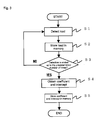
- Fig. 4 is a flowchart showing a procedure of obtaining the load value from the signal supplied from the sensor according to the output characteristic.
- the control unit 16 detects the initial outputs of the sensors 1 to 4. Then, the control unit 16 detects that a load is applied when the outputs of the sensors 1 to 4 are changed (S10). When the output of each sensor is stabilized, the control unit 16 obtains the output of each sensor as the measured value (S11). Then, using the output characteristics of the sensor 1 to 4 stored in the memory 12, the control unit 16 computes the load value in each sensor on the basis of the measured value (S12). For example, it is assumed that the load values obtained by the sensors are 50.50 kg (sensor 1), 49.4 kg (sensor 2), 50.3 kg (sensor 3), and 49.6kg (sensor 4).
- the control unit 16 integrates the load values (S13). The integrated value of 199.8 kg is obtained. Then, the control unit 16 obtains an average value of the integrated value (S14). The average value of 49.95 kg is obtained. The control unit 16 causes the display unit 18 to display the measurement result (average value) (S15).
- the load value is obtained in consideration of the output characteristic of each sensor, so that the high-accuracy measurement can be realized even if the plurality of sensors having the variations in output characteristics are used. Additionally, because the load value is obtained in consideration of the output characteristic of each sensor, it is not necessary that the sensors are selected while the output characteristics of the sensors are uniformed. Therefore, the cost necessary for the selection can be eliminated.
- the load value is obtained with the linear equation in the embodiment, the invention is not limited to the embodiment.
- the load value may be obtained with a quadratic equation or a cubic equation.
Landscapes
- Physics & Mathematics (AREA)
- General Physics & Mathematics (AREA)
- Indication And Recording Devices For Special Purposes And Tariff Metering Devices (AREA)
Abstract
An object of the present invention is to provide a weighing machine which can realize high-accuracy measurement even if a plurality of sensors having variations in output characteristics are used. The weighing machine includes a plurality of sensors, each of which supplies a signal according to a load; a storage unit in which an output characteristic of each sensor is previously stored; and a processing unit which performs processing of the signal supplied from the sensor according to the output characteristic stored in the storage unit.
Description
- The present invention relates to a weighing machine including a plurality of sensors.
- Conventionally, there is known a weighing machine in which a plurality of sensors are used to obtain a weighing value as an integrated value of sensor outputs (see
Patent Documents - Patent Document 1: Japanese Patent Laid-Open No.
2-163617 - Patent Document 2: Japanese Patent Laid-Open No.
2-238327 - Patent Document 3: Japanese Patent Laid-Open No.
2-253130 - Patent Document 4: Japanese Patent Laid-Open No.
2-259429 - Patent Document 5: Japanese Patent Laid-Open No.
3-172720 - Unevenness of characteristics of the plurality of sensors used in the weighing machine causes a problem in that an error is generated when a user disproportionately gets on the weighing machine. When the user incorrectly gets on the weighing machine, the weighing machine cannot display a correct value. Therefore, conventionally, it is necessary to use the sensors by selecting the sensors having the similar characteristics in production. However, the selection becomes troublesome, which causes a decrease in production yield and an increase in cost.
- An object of the invention is to provide a weighing machine which can realize high-accuracy measurement even if a plurality of sensors having variations in output characteristics are used.
- In order to achieve the object, a weighing machine according to an aspect of the invention includes a plurality of sensors, each of which supplies a signal according to a load; a storage unit in which an output characteristic of each sensor is previously stored; and a processing unit which performs processing of the signal supplied from the sensor according to the output characteristic stored in the storage unit.
- According to the invention, the high-accuracy measurement can be realized even if the plurality of sensors having the variations in output characteristics are used.
-
-
Fig. 1 is a block diagram showing a circuit configuration of a weighing machine according to an embodiment of the invention. -
Fig. 2A is a view showing an output characteristic of a sensor used in the weighing machine of the embodiment. -
Fig. 2B is a view showing an output characteristic of a sensor used in the weighing machine of the embodiment. -
Fig. 2C is a view showing an output characteristic of a sensor used in the weighing machine of the embodiment. -
Fig. 2D is a view showing an output characteristic of a sensor used in the weighing machine of the embodiment. -
Fig. 3 is a flowchart showing a procedure of storing output characteristics ofsensors 1 to 4 in a memory 12. -
Fig. 4 is a flowchart showing a procedure of obtaining a load value from a signal supplied from a sensor according to an output characteristic. -
- 10
- Weighing machine
- 12
- Memory
- 14
- Operation unit
- 16
- Control unit
- 18
- Display unit
- 20
- Power supply
- An exemplary embodiment of the invention will be described in detail below with reference to the drawings. However, a technical scope of the invention is not limited to a size, a material, a shape, and a relative layout of a component described in the embodiment unless otherwise stated.
- A weighing machine according to an embodiment of the invention will be described with reference to
Figs. 1 and2A to 2D .Fig. 1 is a block diagram showing a circuit configuration of the weighing machine of the embodiment.Figs. 2A to 2D are views showing an output characteristic of a sensor used in the weighing machine of the embodiment. - As shown in
Fig. 1 , aweighing machine 10 of the embodiment includessensors 1 to 4, a memory 12 in which output characteristics ofsensors 1 to 4 are stored, anoperation unit 14 which is used to provide an instruction such as measurement start, a control unit 16 which performs various kinds of control and computation, adisplay unit 18 which displays a measurement result, and apower supply 20. - Each of the plurality of
sensors 1 to 4 supplies a signal (voltage) according to a load. A load cell which converts a load into a signal to supply the signal can be used as the sensor. As shown inFigs. 2A to 2D , thesensors 1 to 4 of the embodiment have different output characteristics (Load-Voltage Characteristics). Conventionally, it is necessary that plurality of sensors located near the output characteristics of, for example, thesensor 1 be selected and used. This is because the outputs (voltages) of the sensors are simply integrated and used as the weighing value. On the other hand, for thesensors 1 to 4 of the embodiment, as described later, it is not necessary that the output characteristics be uniformed by selecting work. - The output characteristics of the sensors are stored in the memory 12 after the
weighing machine 10 shown inFig. 1 is assembled. Thesensors 1 to 4 are disposed under a stage which the user gets on such that the load is evenly dispersed. Therefore, initial outputs b (V) are supplied from the sensors as shown inFigs. 2A to 2D . An actually measured value may be used as the initial output b, or the initial output b may be obtained from computation as described below.Figs. 2A to 2D show the output characteristics of thesensors 1 to 4 when a predetermined load is evenly applied to the weighingmachine 10 while the weighingmachine 10 is assembled. The output characteristic of the embodiment shows a model output characteristic which is estimated from the output of each sensor when three loads are applied. In the embodiment, a coefficient a and an intercept b are obtained when an equation (for example: V = a x W [kg] + b [V]) is derived from the output characteristic. -
Fig. 3 is a flowchart showing a procedure of storing the output characteristics ofsensors 1 to 4 in the memory 12. The control unit 16 stores the output (voltage value) of each sensor in the memory 12 when a first load (for example, 40 kg) is evenly applied to the weighing machine 10 (S1 and S2). Then, the control unit 16 stores the output of each sensor in the memory 12 when a second load (for example, 80 kg) is evenly applied to the weighing machine 10 (S1 and S2). Then, the control unit 16 stores the output of each sensor in the memory 12 when a third load (for example, 120 kg) is evenly applied to the weighing machine 10 (S1 and S2). When the measurement is ended up to the predetermined number of times (S3), the control unit 16 computes the coefficient a and the intercept b from the plurality of load values in each sensor by a least squares method, and the control unit 16 stores the coefficient a and the intercept b in the memory 12 (S4 and S5). - As described above, the output characteristic of each sensor is previously stored in the memory 12 (corresponding to "storage unit" of the invention). Values of a coefficient a1 and the intercept b1 of the
sensor 1 are stored in the memory 12. Values of a coefficient a2 and the intercept b2 of thesensor 2 are stored in the memory 12. Values of a coefficient a3 and the intercept b3 of thesensor 3 are stored in the memory 12. Values of a coefficient a4 and the intercept b4 of thesensor 4 are stored in the memory 12. A relationship between the coefficient a and intercept b stored in the memory 12 and the output V and load W of the sensor is expressed by the following equation. - Where the coefficients a1, a2, a3, and a4 and the initial outputs b1, b2, b3, and b4 are constants. Therefore, a constant load value (kg) is determined for the signal (V) supplied from the sensor.
- The control unit 16 (corresponding to "processing unit" of the invention) performs processing of the signal supplied from the sensor according to the output characteristic stored in the memory 12.
Fig. 4 is a flowchart showing a procedure of obtaining the load value from the signal supplied from the sensor according to the output characteristic. - A user presses a measurement button of the
operation unit 14 to start the weighing measurement (START). The control unit 16 detects the initial outputs of thesensors 1 to 4. Then, the control unit 16 detects that a load is applied when the outputs of thesensors 1 to 4 are changed (S10). When the output of each sensor is stabilized, the control unit 16 obtains the output of each sensor as the measured value (S11). Then, using the output characteristics of thesensor 1 to 4 stored in the memory 12, the control unit 16 computes the load value in each sensor on the basis of the measured value (S12). For example, it is assumed that the load values obtained by the sensors are 50.50 kg (sensor 1), 49.4 kg (sensor 2), 50.3 kg (sensor 3), and 49.6kg (sensor 4). The control unit 16 integrates the load values (S13). The integrated value of 199.8 kg is obtained. Then, the control unit 16 obtains an average value of the integrated value (S14). The average value of 49.95 kg is obtained. The control unit 16 causes thedisplay unit 18 to display the measurement result (average value) (S15). - Thus, the load value is obtained in consideration of the output characteristic of each sensor, so that the high-accuracy measurement can be realized even if the plurality of sensors having the variations in output characteristics are used. Additionally, because the load value is obtained in consideration of the output characteristic of each sensor, it is not necessary that the sensors are selected while the output characteristics of the sensors are uniformed. Therefore, the cost necessary for the selection can be eliminated.
- Although the load value is obtained with the linear equation in the embodiment, the invention is not limited to the embodiment. For example, the load value may be obtained with a quadratic equation or a cubic equation.
Claims (2)
- A weighing machine comprising:a plurality of sensors, each of which supplies a signal according to a load;a storage unit in which an output characteristic of each sensor is previously stored; anda processing unit which performs processing of the signal supplied from the sensor according to the output characteristic stored in the storage unit.
- The weighing machine according to claim 1, wherein the processing unit obtains a load value according to the signal supplied from each of the plurality of sensors using the output characteristic stored in the storage unit.
Applications Claiming Priority (2)
| Application Number | Priority Date | Filing Date | Title |
|---|---|---|---|
| JP2006072539A JP2007248282A (en) | 2006-03-16 | 2006-03-16 | Bathroom scale |
| PCT/JP2007/052366 WO2007108250A1 (en) | 2006-03-16 | 2007-02-09 | Weighing machine |
Publications (1)
| Publication Number | Publication Date |
|---|---|
| EP1998151A1 true EP1998151A1 (en) | 2008-12-03 |
Family
ID=38522287
Family Applications (1)
| Application Number | Title | Priority Date | Filing Date |
|---|---|---|---|
| EP07708302A Withdrawn EP1998151A1 (en) | 2006-03-16 | 2007-02-09 | Weighing machine |
Country Status (3)
| Country | Link |
|---|---|
| EP (1) | EP1998151A1 (en) |
| JP (1) | JP2007248282A (en) |
| WO (1) | WO2007108250A1 (en) |
Families Citing this family (1)
| Publication number | Priority date | Publication date | Assignee | Title |
|---|---|---|---|---|
| JP7818824B2 (en) * | 2022-10-11 | 2026-02-24 | 国立研究開発法人農業・食品産業技術総合研究機構 | Manufacturing method of measuring device |
Family Cites Families (7)
| Publication number | Priority date | Publication date | Assignee | Title |
|---|---|---|---|---|
| JPH02163617A (en) | 1988-12-16 | 1990-06-22 | Tokyo Electric Co Ltd | load cell scale |
| JPH02238327A (en) | 1989-03-13 | 1990-09-20 | Tokyo Electric Co Ltd | Load cell balance |
| JPH02253130A (en) | 1989-03-28 | 1990-10-11 | Tokyo Electric Co Ltd | load cell scale |
| JP2528181B2 (en) | 1989-03-30 | 1996-08-28 | 株式会社テック | Load cell scale |
| JPH07113576B2 (en) | 1989-11-30 | 1995-12-06 | 株式会社テック | Load cell scale |
| JPH03246424A (en) * | 1990-02-26 | 1991-11-01 | Tokyo Electric Co Ltd | load cell scale |
| JPH0572021A (en) * | 1991-09-10 | 1993-03-23 | Tokyo Electric Co Ltd | Multi load cell type balance |
-
2006
- 2006-03-16 JP JP2006072539A patent/JP2007248282A/en not_active Withdrawn
-
2007
- 2007-02-09 EP EP07708302A patent/EP1998151A1/en not_active Withdrawn
- 2007-02-09 WO PCT/JP2007/052366 patent/WO2007108250A1/en not_active Ceased
Non-Patent Citations (1)
| Title |
|---|
| See references of WO2007108250A1 * |
Also Published As
| Publication number | Publication date |
|---|---|
| JP2007248282A (en) | 2007-09-27 |
| WO2007108250A1 (en) | 2007-09-27 |
Similar Documents
| Publication | Publication Date | Title |
|---|---|---|
| US5434495A (en) | Cognition device for battery residual capacity | |
| US6523271B2 (en) | Method of adjusting drive current of magnetism sensor and electronic azimuth meter | |
| JP4100869B2 (en) | Multi-range transition method and apparatus for process control sensor | |
| JP7006480B2 (en) | Image forming device | |
| JP5170851B2 (en) | Storage battery charge state detection method and storage battery charge state detection device | |
| EP2075554A1 (en) | Weighing machine | |
| US20040155663A1 (en) | Sensor read out | |
| EP1736785A1 (en) | Battery voltage monitoring | |
| US20090057038A1 (en) | Load cell-type electronic balance | |
| US6696697B2 (en) | Roughness measuring method and apparatus, using a filter having a plurality of cutoff values | |
| JP2008198817A (en) | Semiconductor device and trimming method thereof | |
| US8604939B2 (en) | Electronic balance | |
| US6486636B1 (en) | Rechargeable battery measurement and calibration system and method | |
| US20090058516A1 (en) | Sensor apparatus having sensor element | |
| JP4542349B2 (en) | Zero measuring method and weighing device | |
| JP2007248282A (en) | Bathroom scale | |
| US6819100B2 (en) | Method of creating conversion table for distance detection and displacement sensor | |
| JP2007085843A (en) | Current sensor failure detection apparatus and method | |
| JP2005252794A (en) | Method and device for correcting input signal | |
| JP3231182B2 (en) | Operation input device | |
| KR100320072B1 (en) | Method of controling electronic scales | |
| US6201397B1 (en) | Device for measuring and displaying the operating autonomy of a storage battery | |
| JP4771391B2 (en) | Hysteresis correction method for weighing device | |
| JP2009053077A (en) | Load measurement device and error correction method therefor | |
| KR100236217B1 (en) | Reference value automatic compensation method for digital multimeter |
Legal Events
| Date | Code | Title | Description |
|---|---|---|---|
| PUAI | Public reference made under article 153(3) epc to a published international application that has entered the european phase |
Free format text: ORIGINAL CODE: 0009012 |
|
| 17P | Request for examination filed |
Effective date: 20081013 |
|
| AK | Designated contracting states |
Kind code of ref document: A1 Designated state(s): DE ES FR GB IT |
|
| RIN1 | Information on inventor provided before grant (corrected) |
Inventor name: KUBO, NOBUO |
|
| STAA | Information on the status of an ep patent application or granted ep patent |
Free format text: STATUS: THE APPLICATION HAS BEEN WITHDRAWN |
|
| 18W | Application withdrawn |
Effective date: 20090205 |