EP1998090A2 - Seal, vehicle cab and chassis provided with such a seal, and the use of such a seal - Google Patents
Seal, vehicle cab and chassis provided with such a seal, and the use of such a seal Download PDFInfo
- Publication number
- EP1998090A2 EP1998090A2 EP20080156251 EP08156251A EP1998090A2 EP 1998090 A2 EP1998090 A2 EP 1998090A2 EP 20080156251 EP20080156251 EP 20080156251 EP 08156251 A EP08156251 A EP 08156251A EP 1998090 A2 EP1998090 A2 EP 1998090A2
- Authority
- EP
- European Patent Office
- Prior art keywords
- brush
- seal
- cab
- bristles
- radiator
- Prior art date
- Legal status (The legal status is an assumption and is not a legal conclusion. Google has not performed a legal analysis and makes no representation as to the accuracy of the status listed.)
- Granted
Links
Images


Classifications
-
- F—MECHANICAL ENGINEERING; LIGHTING; HEATING; WEAPONS; BLASTING
- F16—ENGINEERING ELEMENTS AND UNITS; GENERAL MEASURES FOR PRODUCING AND MAINTAINING EFFECTIVE FUNCTIONING OF MACHINES OR INSTALLATIONS; THERMAL INSULATION IN GENERAL
- F16J—PISTONS; CYLINDERS; SEALINGS
- F16J15/00—Sealings
- F16J15/16—Sealings between relatively-moving surfaces
- F16J15/32—Sealings between relatively-moving surfaces with elastic sealings, e.g. O-rings
- F16J15/3284—Sealings between relatively-moving surfaces with elastic sealings, e.g. O-rings characterised by their structure; Selection of materials
- F16J15/3288—Filamentary structures, e.g. brush seals
-
- B—PERFORMING OPERATIONS; TRANSPORTING
- B60—VEHICLES IN GENERAL
- B60R—VEHICLES, VEHICLE FITTINGS, OR VEHICLE PARTS, NOT OTHERWISE PROVIDED FOR
- B60R13/00—Elements for body-finishing, identifying, or decorating; Arrangements or adaptations for advertising purposes
- B60R13/06—Sealing strips
-
- B—PERFORMING OPERATIONS; TRANSPORTING
- B62—LAND VEHICLES FOR TRAVELLING OTHERWISE THAN ON RAILS
- B62D—MOTOR VEHICLES; TRAILERS
- B62D33/00—Superstructures for load-carrying vehicles
- B62D33/06—Drivers' cabs
- B62D33/063—Drivers' cabs movable from one position into at least one other position, e.g. tiltable, pivotable about a vertical axis, displaceable from one side of the vehicle to the other
- B62D33/073—Drivers' cabs movable from one position into at least one other position, e.g. tiltable, pivotable about a vertical axis, displaceable from one side of the vehicle to the other characterised by special adaptations of vehicle control devices
Definitions
- the present invention relates to a seal between a vehicle cab and a vehicle chassis.
- the invention relates also to a vehicle cab and a vehicle chassis provided with such a seal and also to using such a seal.
- a majority of today's trucks have the engine situated in the chassis under the cab, and the cab has typically an arched underside serving as the upper delineating surface of the engine compartment.
- Below the engine, which is fastened to the chassis there are often cowlings intended inter alia to reduce the noise from the engine.
- the truck cab is connected to the chassis via a multitude of devices intended inter alia to provide good riding comfort, e.g. by springing, shock absorption, anti-roll stabilisation and vibration damping.
- the truck cab and hence also the upper delineating surface of the engine compartment are thus fastened movably to the chassis.
- the forward side of the engine compartment is usually delineated by the various cooling elements of the vehicle, and the engine compartment is substantially open rearwards to make it possible for air to flow through the radiator, through the engine compartment past the engine and out from the vehicle via the rear aperture of the engine compartment.
- the various cooling elements of the vehicle which are fastened to the chassis
- the cab which is fastened movably relative to the cooling elements
- Typical cab movements relative to the chassis are quite small sideways, slightly larger in the travelling direction of the vehicle and quite large vertically.
- An object of the invention is to provide a simple, inexpensive, durable and effective seal of a gap between a vehicle chassis and a vehicle cab. This is achieved by the features indicated in the claims set out below.
- the seal takes the form of a brush.
- a brush is a surprisingly simple way of bridging, with good sealing effect, the varying gaps which occur between the chassis and the vehicle cab.
- "brush” means a device with a body to which a plurality of elongate, narrow, springy and flexible bristles are fastened. Paint brushes, brooms, mats with fringes and furs are examples of commonly used brushes which fall within this definition.
- a brush may also be configured in other ways and still be covered by the attached claims.
- brush also means, for example, a device to which a plurality of elongate rubber tabs are fastened at their short end, or else a rubber strip which is "fringed" on one long side.
- the brush may be so configured that its body is adapted to being connected to a radiator on the vehicle chassis, in which case the body of the brush may comprise a small number of rectilinear brush elements extending along the usual rectangular shape of the radiator.
- the body may nevertheless also be adapted to being connected to the vehicle cab.
- the brush may have a greater width than the width of a gap between the vehicle chassis and the vehicle cab, making it possible for the seal to maintain its function even during relative movement between the vehicle chassis and the vehicle cab.
- the bristles of a brush may be cut to shape in such a way that their length varies along the extent of the brush, making it easy for the brush to be so shaped as to seal against complicated structures and against components mounted on the opposite surface.
- the brush may further be provided with a fin, which may comprise a thin layer of a flexible material, e.g. plastic, fastened in the body and running in the same direction as the bristles.
- the fin helps to render the brush denser, while at the same time the bristles help to give the fin firmness and cause it to protrude at a suitable angle from the body.
- the bristles of the brush are made of plastic, such as polyethylene terephthalate, polybutene terephthalate or polyamide.
- the body of the brush may be made of, for example, metal, plastic, rubber or other suitable material.
- the bristles of the brush may further have their one end fastened in a first body and their other end in a second body, the first body being adapted to being connected to the chassis and the second to the cab.
- the bristles thus have no free ends but have both ends fastened in the respective bodies.
- the two bodies are adapted to being fastened with their backs towards the chassis/radiator and the cab respectively.
- the bristles may need to be longer than the distance between the chassis and the cab. It is also conceivable for the bristles of the brush to be elastic.
- the bristles of the brush may also have their one end fastened in a first body and their other end freely accommodated in a slit in a second body, making it easy for the seal to maintain its function during limited movements between the chassis and the cab.
- the brush is provided with the bristles which run at a different angle relative to the other bristles of the brush, making it possible, for example, to seal a gap which is longer than the body of the brush.
- the invention is not limited to a single brush.
- Combinations of seals in the form of brushes e.g. a plurality of brushes arranged relative to the radiator, the cab, the cooler and the radiator, side by side, in parallel, overlapping or on opposite sides, are comprised within the concept of the invention.
- the invention thus provides a seal between a chassis and a cab which is simple, easy to manufacture and fit, inexpensive and durable.
- the seal allows better cooling of, inter alia, charge air, EGR and engine, making possible not only lower emissions but also higher power output.
- a further advantage is that the radiator fan can be allowed to rotate more slowly while maintaining the same cooling effect, thus leading to lower noise levels.
- FIG. 1A is a schematic view of the devices situated behind the front hatch of a modern truck.
- a radiator 12 is installed on a truck chassis 10.
- a cab 14 is also connected to the chassis 10 via springs 16, 17, and the underside 18 of the cab serves as a delineating surface for the engine compartment. Between the radiator and the cab there are side gaps 20, 21 and an upper gap 22, to enable the cab to move relative to the chassis and the radiator. The cab can move relative to the chassis in any direction. Below the radiator there is also a lower gap 24; sealing this gap is no problem, since the radiator is not fastened movably to the chassis.
- the underside 18 of the cab may have a complicated shape, here depicted in the form of recesses and protrusions 26.
- FIG. 1B is a schematic view of the same device as in FIG. 1A , but the side gap 20 ( FIG. 1A ) is sealed by a seal 28 according to the invention.
- the seal 28 comprises a brush with its body 30 connected to the radiator 12 in such a way that the bristles 32 of the brush abut against the underside 18 of the cab ( FIG. 1A ) and seal the side gap 20 ( FIG. 1A ).
- the bristles 32 of the brush are cut to shape in order also to seal in the space adjacent to the spring 16.
- a brush may similarly be cut to shape to seal against the recesses and protrusions 26.
- the bristles of the brush may also be fastened to mutually opposite bodies 30, 31, one of them connected to the radiator 12 and the other to the cab 14.
- the length of the bristles may be such as to allow movements between the radiator 12 and the cab 14. They may for example, in an undepicted manner, be bent or provided with folds between the radiator and the cab.
- the bristles need not necessarily be fastened to both of the bodies 30, 31, as free ends of the bristles may, in the manner indicated in the cutaway portion of FIG. 3A , be freely accommodated in a slit in one of the mutually opposite bodies 30, 31, which slit is of such a depth that the bristles of the brush here again maintain their sealing function during movements between the radiator 12 and the cab 14.
- FIG. 2 is a schematic sideview in section of the engine compartment of a truck.
- the engine compartment is delineated substantially by the chassis 10, the radiator 12 and the cab 14.
- a further cooling element 34 may be installed on the chassis.
- An engine 36 is situated behind the cooling elements 12, 34 which are so arranged as to enable an air flow from in front to pass through them, past the engine and out through the rear aperture 38 of the engine compartment. If there is great flow resistance in this passage, part of the air will leak out through the gaps 20, 21 ( FIG. 1A ), 22 and raise the temperature of the air in front of the radiator; this leakage may accordingly be limited by seals, e.g. 28 ( FIG. 1 B) according to the invention.
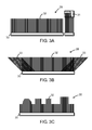
- FIG. 3A illustrates schematically an example of an embodiment of a seal 28 in the form of a brush which comprises a body 30 and bristles 32 fastened to the body.
- FIG. 3B depicts a similar seal in which the brush also has bristles 33 running at different angles from the bristles 32 relative to the body 30.
- the angles and the locations of the bristles are so arranged that three examples of this embodiment which are associated with the radiator 12 and the sealing gaps 20, 21, 22, cover these gaps better than three examples of the embodiment illustrated in FIG. 3A .
- FIG. 3C illustrates schematically an example of an embodiment in which the bristles 32 of the brush are cut to shape to seal against the recesses and protrusions 26.
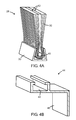
- FIG. 4A illustrates schematically an embodiment of a brush with a fin.
- the configuration of the brush is not important for the invention, but the brush illustrated is merely an example of an ordinary configuration out of many well-known configurations which are usable.
- the bristles 32 of the brush are bent double and clamped in a body 30 by a rod 40 placed in the fold of the bristles 32 and pressed into the body 30.
- the fin 42 is fastened in the body 30 in the same way as the bristles 32.
- the fin 42 need not necessarily extend to the ends of the bristles or the body but may be of any desired width, length and contour (not depicted).
- FIG. 4B depicts schematically an embodiment of a fastening strip 44 for mounting the seal 28 on, for example, a radiator.
- the configuration of the strip is not important for the invention, the strip illustrated is merely one example of an ordinary embodiment out of many well-known embodiments which are usable.
- the gap 46 in the strip is adapted to retaining the body 30 of the brush, and the flange 48 to being fastened to a surface where it is desired to provide a seal.
- the strip 44 may be made of, for example, metal, plastic, rubber or any other suitable material desired.
- the brush may also be so arranged that it can be fastened to the chassis or the radiator without a fastening strip.
Landscapes
- Engineering & Computer Science (AREA)
- Mechanical Engineering (AREA)
- General Engineering & Computer Science (AREA)
- Chemical & Material Sciences (AREA)
- Combustion & Propulsion (AREA)
- Transportation (AREA)
- Body Structure For Vehicles (AREA)
- Seal Device For Vehicle (AREA)
- Cooling, Air Intake And Gas Exhaust, And Fuel Tank Arrangements In Propulsion Units (AREA)
- Sealing Devices (AREA)
Abstract
Description
- The present invention relates to a seal between a vehicle cab and a vehicle chassis.
- The invention relates also to a vehicle cab and a vehicle chassis provided with such a seal and also to using such a seal.
- Increasing worldwide environmental awareness has resulted in more stringent truck emission requirements not only from authorities in many countries but also from truck users and society at large. Ways of meeting the emission requirements include reducing nitrogen oxide (NOx) contents, e.g. by improved EGR (exhaust gas recirculation), which lowers the combustion temperature and thereby reduces the formation of NOx, and improved turbocharging. At the same time, truck users want higher engine power to enable them to carry heavier loads and keep up with increasing traffic speeds. Both reducing emissions and increasing the engine power entail increasing requirements for more effective cooling of the engine and of EGR and turbocharging air.
- A majority of today's trucks have the engine situated in the chassis under the cab, and the cab has typically an arched underside serving as the upper delineating surface of the engine compartment. Below the engine, which is fastened to the chassis, there are often cowlings intended inter alia to reduce the noise from the engine. The truck cab is connected to the chassis via a multitude of devices intended inter alia to provide good riding comfort, e.g. by springing, shock absorption, anti-roll stabilisation and vibration damping. The truck cab and hence also the upper delineating surface of the engine compartment are thus fastened movably to the chassis. The forward side of the engine compartment is usually delineated by the various cooling elements of the vehicle, and the engine compartment is substantially open rearwards to make it possible for air to flow through the radiator, through the engine compartment past the engine and out from the vehicle via the rear aperture of the engine compartment. Between the various cooling elements of the vehicle, which are fastened to the chassis, and the cab, which is fastened movably relative to the cooling elements, there is an air gap to prevent chafing and mutual impacts when the vehicle in motion shifts relative to the cooling elements. Typical cab movements relative to the chassis are quite small sideways, slightly larger in the travelling direction of the vehicle and quite large vertically.
- In large parts of the world there are rules limiting the length of the vehicles which may be driven on public roads. At the same time there is a desire among truck users to be able to carry as large loads as possible; thus truck manufacturers have cause to make the truck cab and the engine compartment situated under it as short as possible so that the load platform or cargo space can be made as long as possible. This means that space in the engine compartment is limited and more specifically that the distance between the engine and the radiator situated at the front of the chassis and constituting the front wall of the engine compartment is limited. The distance between the engine and the sidewalls of the engine compartment is likewise limited. These narrow spaces result in substantial flow resistance to the incoming air passing through the radiator and through the engine compartment. This flow resistance leads to a considerable proportion of the air which enters the engine compartment through the radiator leaking out to the front or sides of or above the radiator via the gaps between the cab and the chassis/radiator. The fact that this air, having passed through the radiator, is warmer than air at normal outside temperature is a problem in that part of it is sucked back in through the radiator and thereby raises the temperature of the radiator air, with consequent impairment of cooling. This problem has long been well known and has been partly solved by sheetlike rubber seals between the radiator and the cab.
- There are various problems, however, with using rubber seals for this purpose. The large vertical movement of the cab gives rise to a large movement along the direction of the extent of the seal on the sides of the radiator, which movement is likely to tear apart the seals along the sides of the radiator, since the seals are not flexible in this direction. In addition, the surface of the cab which faces the engine compartment often has a complicated shape with structures pressed in the sheetmetal and with various items mounted on the surface. This leads to the need for a plurality of rubber components for effecting reasonable sealing of the gaps, and hence to increased costs not only for material and stockholding but also for assembly work. Moreover, on many truck models the cab is tiltable forwards to allow access to the engine for servicing and maintenance; this further complicates the seal problem, since the tilt movement needs good clearance between cab and radiator.
- There is no prior art solution to the problem of achieving an effective and inexpensive seal which does not risk being torn apart by the large cab movements.
- An object of the invention is to provide a simple, inexpensive, durable and effective seal of a gap between a vehicle chassis and a vehicle cab. This is achieved by the features indicated in the claims set out below.
- According to a version of the invention, the seal takes the form of a brush. A brush is a surprisingly simple way of bridging, with good sealing effect, the varying gaps which occur between the chassis and the vehicle cab. In this description, "brush" means a device with a body to which a plurality of elongate, narrow, springy and flexible bristles are fastened. Paint brushes, brooms, mats with fringes and furs are examples of commonly used brushes which fall within this definition. A brush may also be configured in other ways and still be covered by the attached claims. In this context, brush also means, for example, a device to which a plurality of elongate rubber tabs are fastened at their short end, or else a rubber strip which is "fringed" on one long side.
- According to a version of the invention, the brush may be so configured that its body is adapted to being connected to a radiator on the vehicle chassis, in which case the body of the brush may comprise a small number of rectilinear brush elements extending along the usual rectangular shape of the radiator.
- The body may nevertheless also be adapted to being connected to the vehicle cab.
- The brush may have a greater width than the width of a gap between the vehicle chassis and the vehicle cab, making it possible for the seal to maintain its function even during relative movement between the vehicle chassis and the vehicle cab.
- The bristles of a brush may be cut to shape in such a way that their length varies along the extent of the brush, making it easy for the brush to be so shaped as to seal against complicated structures and against components mounted on the opposite surface.
- The brush may further be provided with a fin, which may comprise a thin layer of a flexible material, e.g. plastic, fastened in the body and running in the same direction as the bristles. The fin helps to render the brush denser, while at the same time the bristles help to give the fin firmness and cause it to protrude at a suitable angle from the body.
- In an embodiment, the bristles of the brush are made of plastic, such as polyethylene terephthalate, polybutene terephthalate or polyamide. The body of the brush may be made of, for example, metal, plastic, rubber or other suitable material.
- The bristles of the brush may further have their one end fastened in a first body and their other end in a second body, the first body being adapted to being connected to the chassis and the second to the cab. In this case the bristles thus have no free ends but have both ends fastened in the respective bodies. The two bodies are adapted to being fastened with their backs towards the chassis/radiator and the cab respectively. In this case, the bristles may need to be longer than the distance between the chassis and the cab. It is also conceivable for the bristles of the brush to be elastic.
- However, the bristles of the brush may also have their one end fastened in a first body and their other end freely accommodated in a slit in a second body, making it easy for the seal to maintain its function during limited movements between the chassis and the cab.
- In another embodiment, the brush is provided with the bristles which run at a different angle relative to the other bristles of the brush, making it possible, for example, to seal a gap which is longer than the body of the brush.
- The invention is not limited to a single brush. Combinations of seals in the form of brushes, e.g. a plurality of brushes arranged relative to the radiator, the cab, the cooler and the radiator, side by side, in parallel, overlapping or on opposite sides, are comprised within the concept of the invention.
- The invention thus provides a seal between a chassis and a cab which is simple, easy to manufacture and fit, inexpensive and durable. The seal allows better cooling of, inter alia, charge air, EGR and engine, making possible not only lower emissions but also higher power output. A further advantage is that the radiator fan can be allowed to rotate more slowly while maintaining the same cooling effect, thus leading to lower noise levels.
- Other features and advantages of the invention may be indicated by the claims and the description of embodiment examples set out below.
-
-
FIG. 1A is a schematic view, as seen from in front, of part of a truck chassis, part of a cab and a radiator situated between them. -
FIG. 1B is a schematic view, as seen from in front, of part of a truck chassis, part of a cab and a radiator situated between them, in which one of the gaps between the cab and the radiator is provided with a seal according to the invention. -
FIG. 2 is a schematic sideview in section of an engine compartment of a truck. -
FIG. 3A is a schematic illustration of a brush. -
FIG. 3B is a schematic illustration of a brush with a plurality of sets of bristles which run in different directions. -
FIG. 3C is a schematic illustration of a brush cut to shape. -
FIG. 4A is a schematic sectional view of a brush with a fin. -
FIG. 4B is a schematic sectional view of a mounting strip intended for mounting a brush on a surface. -
FIG. 1A is a schematic view of the devices situated behind the front hatch of a modern truck. Aradiator 12 is installed on atruck chassis 10. Acab 14 is also connected to thechassis 10 viasprings 16, 17, and theunderside 18 of the cab serves as a delineating surface for the engine compartment. Between the radiator and the cab there areside gaps upper gap 22, to enable the cab to move relative to the chassis and the radiator. The cab can move relative to the chassis in any direction. Below the radiator there is also alower gap 24; sealing this gap is no problem, since the radiator is not fastened movably to the chassis. Theunderside 18 of the cab may have a complicated shape, here depicted in the form of recesses andprotrusions 26. -
FIG. 1B is a schematic view of the same device as inFIG. 1A , but the side gap 20 (FIG. 1A ) is sealed by aseal 28 according to the invention. Theseal 28 comprises a brush with itsbody 30 connected to theradiator 12 in such a way that thebristles 32 of the brush abut against theunderside 18 of the cab (FIG. 1A ) and seal the side gap 20 (FIG. 1A ). Thebristles 32 of the brush are cut to shape in order also to seal in the space adjacent to the spring 16. A brush may similarly be cut to shape to seal against the recesses andprotrusions 26. - As further indicated at the upper portion of the
brush 28 inFIG. 1B , the bristles of the brush may also be fastened to mutuallyopposite bodies radiator 12 and the other to thecab 14. In this case, the length of the bristles may be such as to allow movements between theradiator 12 and thecab 14. They may for example, in an undepicted manner, be bent or provided with folds between the radiator and the cab. In that case, however, the bristles need not necessarily be fastened to both of thebodies FIG. 3A , be freely accommodated in a slit in one of the mutuallyopposite bodies radiator 12 and thecab 14. -
FIG. 2 is a schematic sideview in section of the engine compartment of a truck. The engine compartment is delineated substantially by thechassis 10, theradiator 12 and thecab 14. Afurther cooling element 34 may be installed on the chassis. Anengine 36 is situated behind thecooling elements rear aperture 38 of the engine compartment. If there is great flow resistance in this passage, part of the air will leak out through thegaps 20, 21 (FIG. 1A ), 22 and raise the temperature of the air in front of the radiator; this leakage may accordingly be limited by seals, e.g. 28 (FIG. 1 B) according to the invention. -
FIG. 3A illustrates schematically an example of an embodiment of aseal 28 in the form of a brush which comprises abody 30 and bristles 32 fastened to the body. -
FIG. 3B depicts a similar seal in which the brush also hasbristles 33 running at different angles from thebristles 32 relative to thebody 30. In this specific example, the angles and the locations of the bristles are so arranged that three examples of this embodiment which are associated with theradiator 12 and the sealinggaps FIG. 3A . -
FIG. 3C illustrates schematically an example of an embodiment in which thebristles 32 of the brush are cut to shape to seal against the recesses andprotrusions 26. -
FIG. 4A illustrates schematically an embodiment of a brush with a fin. The configuration of the brush is not important for the invention, but the brush illustrated is merely an example of an ordinary configuration out of many well-known configurations which are usable. In this example, thebristles 32 of the brush are bent double and clamped in abody 30 by arod 40 placed in the fold of thebristles 32 and pressed into thebody 30. In this embodiment, thefin 42 is fastened in thebody 30 in the same way as thebristles 32. Thefin 42 need not necessarily extend to the ends of the bristles or the body but may be of any desired width, length and contour (not depicted). -
FIG. 4B depicts schematically an embodiment of afastening strip 44 for mounting theseal 28 on, for example, a radiator. The configuration of the strip is not important for the invention, the strip illustrated is merely one example of an ordinary embodiment out of many well-known embodiments which are usable. The gap 46 in the strip is adapted to retaining thebody 30 of the brush, and theflange 48 to being fastened to a surface where it is desired to provide a seal. Thestrip 44 may be made of, for example, metal, plastic, rubber or any other suitable material desired. The brush may also be so arranged that it can be fastened to the chassis or the radiator without a fastening strip. - The description set out above is primarily intended for facilitate comprehension and no unnecessary limitations of the invention are to be inferred therefrom. The modifications which will be obvious to one skilled in the art from perusing the description may be implemented without departing from the concept of the invention or the scope of the claims set out below.
Claims (13)
- A seal adapted to sealing between a vehicle chassis (10) and a vehicle cab (14), characterised in that the seal takes the form of a brush (28).
- A seal according to claim 1, in which a body (30) of the seal (28) is adapted to being connected to a radiator (12) on the vehicle chassis (10).
- A seal according to claim 1, in which a body (30) of the seal (28) is adapted to being connected to the vehicle cab (14).
- A seal according to any one of the foregoing claims, in which the brush (28) has a greater width than the width of a gap between the vehicle chassis (10) and the vehicle cab (14).
- A seal according to any one of the foregoing claims, in which bristles (32) of the brush (28) are cut to shape in such a way that their length varies along the extent of the brush.
- A seal according to any one of the foregoing claims, in which a brush (28) has a fin (42).
- A seal according to any one of the foregoing claims, in which the bristles (32) of the brush (28) are made of plastic such as polyethylene terephthalate, polybutene terephthalate or polyamide.
- A seal according to any one of the foregoing claims, in which the bristles of the brush have their one end fastened in a first body (30) and their other end in a second body (31), the first body being adapted to being connected to the vehicle chassis (10) and the second body being adapted to being connected to the vehicle cab (14).
- A seal according to any one of claims 1-7, in which the bristles of the brush have their one end fastened in a first body (30) and their other end freely accommodated in a slit in a second body (31).
- A seal according to any one of the foregoing claims, in which the brush (28) is provided with bristles (33) which run at a different angle from other bristles (32) of the brush.
- A vehicle cab (14) provided with a seal according to any one of the foregoing claims.
- A vehicle chassis (10) provided with a seal according to any one of the foregoing claims.
- Using a seal according to any one of the foregoing claims.
Applications Claiming Priority (1)
| Application Number | Priority Date | Filing Date | Title |
|---|---|---|---|
| SE0701267A SE531182C2 (en) | 2007-05-25 | 2007-05-25 | Seal, vehicle cab and chassis provided with such seal and use of such seal |
Related Parent Applications (1)
| Application Number | Title | Priority Date | Filing Date |
|---|---|---|---|
| SE0701267 Previously-Filed-Application | 2007-05-25 |
Publications (3)
| Publication Number | Publication Date |
|---|---|
| EP1998090A2 true EP1998090A2 (en) | 2008-12-03 |
| EP1998090A3 EP1998090A3 (en) | 2011-08-10 |
| EP1998090B1 EP1998090B1 (en) | 2015-07-29 |
Family
ID=39720560
Family Applications (1)
| Application Number | Title | Priority Date | Filing Date |
|---|---|---|---|
| EP08156251.4A Active EP1998090B1 (en) | 2007-05-25 | 2008-05-15 | Seal, vehicle cab and chassis provided with such a seal, and the use of such a seal |
Country Status (3)
| Country | Link |
|---|---|
| EP (1) | EP1998090B1 (en) |
| BR (1) | BRPI0801526B1 (en) |
| SE (1) | SE531182C2 (en) |
Cited By (4)
| Publication number | Priority date | Publication date | Assignee | Title |
|---|---|---|---|---|
| WO2011147395A1 (en) * | 2010-05-28 | 2011-12-01 | Mtu Aero Engines Gmbh | Method for fastening a brush sealing element in a groove of a housing segment |
| WO2017044026A1 (en) * | 2015-09-09 | 2017-03-16 | BAE Systems Hägglunds Aktiebolag | Sealing arrangement for a vehicle |
| US9636996B1 (en) | 2015-10-07 | 2017-05-02 | Ford Global Technologies Llc | High-efficiency body-on-frame air deflector sealing system |
| US10391856B2 (en) | 2017-06-23 | 2019-08-27 | Ford Global Technologies Llc | Air deflector with improved drainage |
Family Cites Families (6)
| Publication number | Priority date | Publication date | Assignee | Title |
|---|---|---|---|---|
| JPS5585521U (en) * | 1978-12-11 | 1980-06-12 | ||
| DE3405921C2 (en) * | 1984-02-18 | 1987-02-05 | Daimler-Benz Ag, 7000 Stuttgart | Operating station for tractors and work machines |
| DE3514382C1 (en) * | 1985-04-20 | 1986-06-12 | Motoren Turbinen Union | Brush seal |
| ATE212691T1 (en) * | 1993-06-23 | 2002-02-15 | Schlegel Pty Ltd | METHOD FOR PRODUCING AN LONG STRETCH BARRIER |
| JP3364141B2 (en) * | 1997-12-04 | 2003-01-08 | 槌屋ティスコ株式会社 | Lever groove seal structure of operation lever cover member |
| US20040173969A1 (en) * | 2001-10-25 | 2004-09-09 | Smith Walter J. | Turbine brush seal |
-
2007
- 2007-05-25 SE SE0701267A patent/SE531182C2/en unknown
-
2008
- 2008-05-15 EP EP08156251.4A patent/EP1998090B1/en active Active
- 2008-05-21 BR BRPI0801526-0A patent/BRPI0801526B1/en active IP Right Grant
Non-Patent Citations (1)
| Title |
|---|
| None |
Cited By (8)
| Publication number | Priority date | Publication date | Assignee | Title |
|---|---|---|---|---|
| WO2011147395A1 (en) * | 2010-05-28 | 2011-12-01 | Mtu Aero Engines Gmbh | Method for fastening a brush sealing element in a groove of a housing segment |
| US9759077B2 (en) | 2010-05-28 | 2017-09-12 | Mtu Aero Engines Gmbh | Method for fastening a brush sealing element in a groove of a housing segment |
| WO2017044026A1 (en) * | 2015-09-09 | 2017-03-16 | BAE Systems Hägglunds Aktiebolag | Sealing arrangement for a vehicle |
| CN108055838A (en) * | 2015-09-09 | 2018-05-18 | 贝以系统哈格伦斯公司 | Sealing equipment for vehicles |
| AU2016319735B2 (en) * | 2015-09-09 | 2020-10-08 | BAE Systems Hägglunds Aktiebolag | Sealing arrangement for a vehicle |
| US10871233B2 (en) | 2015-09-09 | 2020-12-22 | BAE Systems Hägglunds Aktiebolag | Amphibious vehicle with a sealing arrangement |
| US9636996B1 (en) | 2015-10-07 | 2017-05-02 | Ford Global Technologies Llc | High-efficiency body-on-frame air deflector sealing system |
| US10391856B2 (en) | 2017-06-23 | 2019-08-27 | Ford Global Technologies Llc | Air deflector with improved drainage |
Also Published As
| Publication number | Publication date |
|---|---|
| EP1998090A3 (en) | 2011-08-10 |
| SE0701267L (en) | 2008-11-26 |
| BRPI0801526A2 (en) | 2009-01-20 |
| BRPI0801526B1 (en) | 2019-05-14 |
| SE531182C2 (en) | 2009-01-13 |
| EP1998090B1 (en) | 2015-07-29 |
Similar Documents
| Publication | Publication Date | Title |
|---|---|---|
| US10676140B2 (en) | Rear diffusor unit with a flow-directing sealing element | |
| JP5758233B2 (en) | Automotive front structure | |
| JP3640637B2 (en) | Seal structure for vehicle cowl top panel | |
| US8910982B2 (en) | Exhaust gas odor foam blocking structure | |
| EP1998090A2 (en) | Seal, vehicle cab and chassis provided with such a seal, and the use of such a seal | |
| US20150028629A1 (en) | Structure for front part of vehicle | |
| CN212332348U (en) | Battery and fuel tank arrangements for hybrid vehicles | |
| CN110549920B (en) | Panel turnover system | |
| JP5432655B2 (en) | Vehicle separated room connector | |
| US9914340B1 (en) | Vehicle cowl attachment | |
| CN103057604A (en) | Automotive vehicles with front undercarriage protectors | |
| CN104709360B (en) | The mounting structure of baffle side cover | |
| JP2012066764A (en) | Rear body structure of vehicle | |
| JP2013199143A (en) | Roof weather strip for motor vehicle | |
| JPWO2006040814A1 (en) | truck | |
| JP2007118638A (en) | Vehicle hood seal structure | |
| CN2600291Y (en) | Buffer unit for vehicle tail collision | |
| US20070243818A1 (en) | Air Guide for front end cooling | |
| US20140080400A1 (en) | Chmsl grille | |
| JP7276201B2 (en) | Gasket for outer mirror | |
| CN222522441U (en) | Car window sealing structure and car | |
| JPH0120227Y2 (en) | ||
| KR100887570B1 (en) | Truck | |
| KR100502145B1 (en) | Air dam device of automobile | |
| CN103057496A (en) | Automotive vehicle with front tire protector |
Legal Events
| Date | Code | Title | Description |
|---|---|---|---|
| PUAI | Public reference made under article 153(3) epc to a published international application that has entered the european phase |
Free format text: ORIGINAL CODE: 0009012 |
|
| AK | Designated contracting states |
Kind code of ref document: A2 Designated state(s): AT BE BG CH CY CZ DE DK EE ES FI FR GB GR HR HU IE IS IT LI LT LU LV MC MT NL NO PL PT RO SE SI SK TR |
|
| AX | Request for extension of the european patent |
Extension state: AL BA MK RS |
|
| PUAL | Search report despatched |
Free format text: ORIGINAL CODE: 0009013 |
|
| AK | Designated contracting states |
Kind code of ref document: A3 Designated state(s): AT BE BG CH CY CZ DE DK EE ES FI FR GB GR HR HU IE IS IT LI LT LU LV MC MT NL NO PL PT RO SE SI SK TR |
|
| AX | Request for extension of the european patent |
Extension state: AL BA MK RS |
|
| RIC1 | Information provided on ipc code assigned before grant |
Ipc: F16J 15/32 20060101AFI20110707BHEP |
|
| 17P | Request for examination filed |
Effective date: 20120210 |
|
| AKX | Designation fees paid |
Designated state(s): AT BE BG CH CY CZ DE DK EE ES FI FR GB GR HR HU IE IS IT LI LT LU LV MC MT NL NO PL PT RO SE SI SK TR |
|
| 17Q | First examination report despatched |
Effective date: 20130419 |
|
| GRAP | Despatch of communication of intention to grant a patent |
Free format text: ORIGINAL CODE: EPIDOSNIGR1 |
|
| RIC1 | Information provided on ipc code assigned before grant |
Ipc: B62D 33/073 20060101ALI20150311BHEP Ipc: F16J 15/32 20060101AFI20150311BHEP |
|
| INTG | Intention to grant announced |
Effective date: 20150330 |
|
| GRAS | Grant fee paid |
Free format text: ORIGINAL CODE: EPIDOSNIGR3 |
|
| GRAA | (expected) grant |
Free format text: ORIGINAL CODE: 0009210 |
|
| AK | Designated contracting states |
Kind code of ref document: B1 Designated state(s): AT BE BG CH CY CZ DE DK EE ES FI FR GB GR HR HU IE IS IT LI LT LU LV MC MT NL NO PL PT RO SE SI SK TR |
|
| REG | Reference to a national code |
Ref country code: GB Ref legal event code: FG4D |
|
| REG | Reference to a national code |
Ref country code: CH Ref legal event code: EP |
|
| REG | Reference to a national code |
Ref country code: AT Ref legal event code: REF Ref document number: 739586 Country of ref document: AT Kind code of ref document: T Effective date: 20150815 |
|
| REG | Reference to a national code |
Ref country code: IE Ref legal event code: FG4D |
|
| REG | Reference to a national code |
Ref country code: DE Ref legal event code: R096 Ref document number: 602008039215 Country of ref document: DE |
|
| REG | Reference to a national code |
Ref country code: AT Ref legal event code: MK05 Ref document number: 739586 Country of ref document: AT Kind code of ref document: T Effective date: 20150729 |
|
| REG | Reference to a national code |
Ref country code: LT Ref legal event code: MG4D |
|
| REG | Reference to a national code |
Ref country code: NL Ref legal event code: MP Effective date: 20150729 |
|
| PG25 | Lapsed in a contracting state [announced via postgrant information from national office to epo] |
Ref country code: LT Free format text: LAPSE BECAUSE OF FAILURE TO SUBMIT A TRANSLATION OF THE DESCRIPTION OR TO PAY THE FEE WITHIN THE PRESCRIBED TIME-LIMIT Effective date: 20150729 Ref country code: NO Free format text: LAPSE BECAUSE OF FAILURE TO SUBMIT A TRANSLATION OF THE DESCRIPTION OR TO PAY THE FEE WITHIN THE PRESCRIBED TIME-LIMIT Effective date: 20151029 Ref country code: LV Free format text: LAPSE BECAUSE OF FAILURE TO SUBMIT A TRANSLATION OF THE DESCRIPTION OR TO PAY THE FEE WITHIN THE PRESCRIBED TIME-LIMIT Effective date: 20150729 Ref country code: GR Free format text: LAPSE BECAUSE OF FAILURE TO SUBMIT A TRANSLATION OF THE DESCRIPTION OR TO PAY THE FEE WITHIN THE PRESCRIBED TIME-LIMIT Effective date: 20151030 Ref country code: FI Free format text: LAPSE BECAUSE OF FAILURE TO SUBMIT A TRANSLATION OF THE DESCRIPTION OR TO PAY THE FEE WITHIN THE PRESCRIBED TIME-LIMIT Effective date: 20150729 |
|
| PG25 | Lapsed in a contracting state [announced via postgrant information from national office to epo] |
Ref country code: AT Free format text: LAPSE BECAUSE OF FAILURE TO SUBMIT A TRANSLATION OF THE DESCRIPTION OR TO PAY THE FEE WITHIN THE PRESCRIBED TIME-LIMIT Effective date: 20150729 Ref country code: HR Free format text: LAPSE BECAUSE OF FAILURE TO SUBMIT A TRANSLATION OF THE DESCRIPTION OR TO PAY THE FEE WITHIN THE PRESCRIBED TIME-LIMIT Effective date: 20150729 Ref country code: SE Free format text: LAPSE BECAUSE OF FAILURE TO SUBMIT A TRANSLATION OF THE DESCRIPTION OR TO PAY THE FEE WITHIN THE PRESCRIBED TIME-LIMIT Effective date: 20150729 Ref country code: IS Free format text: LAPSE BECAUSE OF FAILURE TO SUBMIT A TRANSLATION OF THE DESCRIPTION OR TO PAY THE FEE WITHIN THE PRESCRIBED TIME-LIMIT Effective date: 20151129 Ref country code: PL Free format text: LAPSE BECAUSE OF FAILURE TO SUBMIT A TRANSLATION OF THE DESCRIPTION OR TO PAY THE FEE WITHIN THE PRESCRIBED TIME-LIMIT Effective date: 20150729 Ref country code: ES Free format text: LAPSE BECAUSE OF FAILURE TO SUBMIT A TRANSLATION OF THE DESCRIPTION OR TO PAY THE FEE WITHIN THE PRESCRIBED TIME-LIMIT Effective date: 20150729 Ref country code: PT Free format text: LAPSE BECAUSE OF FAILURE TO SUBMIT A TRANSLATION OF THE DESCRIPTION OR TO PAY THE FEE WITHIN THE PRESCRIBED TIME-LIMIT Effective date: 20151130 |
|
| PG25 | Lapsed in a contracting state [announced via postgrant information from national office to epo] |
Ref country code: NL Free format text: LAPSE BECAUSE OF FAILURE TO SUBMIT A TRANSLATION OF THE DESCRIPTION OR TO PAY THE FEE WITHIN THE PRESCRIBED TIME-LIMIT Effective date: 20150729 |
|
| REG | Reference to a national code |
Ref country code: FR Ref legal event code: PLFP Year of fee payment: 9 |
|
| PG25 | Lapsed in a contracting state [announced via postgrant information from national office to epo] |
Ref country code: DK Free format text: LAPSE BECAUSE OF FAILURE TO SUBMIT A TRANSLATION OF THE DESCRIPTION OR TO PAY THE FEE WITHIN THE PRESCRIBED TIME-LIMIT Effective date: 20150729 Ref country code: SK Free format text: LAPSE BECAUSE OF FAILURE TO SUBMIT A TRANSLATION OF THE DESCRIPTION OR TO PAY THE FEE WITHIN THE PRESCRIBED TIME-LIMIT Effective date: 20150729 Ref country code: IT Free format text: LAPSE BECAUSE OF FAILURE TO SUBMIT A TRANSLATION OF THE DESCRIPTION OR TO PAY THE FEE WITHIN THE PRESCRIBED TIME-LIMIT Effective date: 20150729 Ref country code: CZ Free format text: LAPSE BECAUSE OF FAILURE TO SUBMIT A TRANSLATION OF THE DESCRIPTION OR TO PAY THE FEE WITHIN THE PRESCRIBED TIME-LIMIT Effective date: 20150729 Ref country code: EE Free format text: LAPSE BECAUSE OF FAILURE TO SUBMIT A TRANSLATION OF THE DESCRIPTION OR TO PAY THE FEE WITHIN THE PRESCRIBED TIME-LIMIT Effective date: 20150729 |
|
| REG | Reference to a national code |
Ref country code: DE Ref legal event code: R097 Ref document number: 602008039215 Country of ref document: DE |
|
| PG25 | Lapsed in a contracting state [announced via postgrant information from national office to epo] |
Ref country code: RO Free format text: LAPSE BECAUSE OF FAILURE TO SUBMIT A TRANSLATION OF THE DESCRIPTION OR TO PAY THE FEE WITHIN THE PRESCRIBED TIME-LIMIT Effective date: 20150729 |
|
| PLBE | No opposition filed within time limit |
Free format text: ORIGINAL CODE: 0009261 |
|
| STAA | Information on the status of an ep patent application or granted ep patent |
Free format text: STATUS: NO OPPOSITION FILED WITHIN TIME LIMIT |
|
| 26N | No opposition filed |
Effective date: 20160502 |
|
| PG25 | Lapsed in a contracting state [announced via postgrant information from national office to epo] |
Ref country code: SI Free format text: LAPSE BECAUSE OF FAILURE TO SUBMIT A TRANSLATION OF THE DESCRIPTION OR TO PAY THE FEE WITHIN THE PRESCRIBED TIME-LIMIT Effective date: 20150729 Ref country code: BE Free format text: LAPSE BECAUSE OF NON-PAYMENT OF DUE FEES Effective date: 20160531 |
|
| PG25 | Lapsed in a contracting state [announced via postgrant information from national office to epo] |
Ref country code: LU Free format text: LAPSE BECAUSE OF FAILURE TO SUBMIT A TRANSLATION OF THE DESCRIPTION OR TO PAY THE FEE WITHIN THE PRESCRIBED TIME-LIMIT Effective date: 20160515 Ref country code: BE Free format text: LAPSE BECAUSE OF FAILURE TO SUBMIT A TRANSLATION OF THE DESCRIPTION OR TO PAY THE FEE WITHIN THE PRESCRIBED TIME-LIMIT Effective date: 20150729 |
|
| REG | Reference to a national code |
Ref country code: CH Ref legal event code: PL |
|
| PG25 | Lapsed in a contracting state [announced via postgrant information from national office to epo] |
Ref country code: CH Free format text: LAPSE BECAUSE OF NON-PAYMENT OF DUE FEES Effective date: 20160531 Ref country code: LI Free format text: LAPSE BECAUSE OF NON-PAYMENT OF DUE FEES Effective date: 20160531 |
|
| REG | Reference to a national code |
Ref country code: IE Ref legal event code: MM4A |
|
| REG | Reference to a national code |
Ref country code: FR Ref legal event code: PLFP Year of fee payment: 10 |
|
| PG25 | Lapsed in a contracting state [announced via postgrant information from national office to epo] |
Ref country code: IE Free format text: LAPSE BECAUSE OF NON-PAYMENT OF DUE FEES Effective date: 20160515 |
|
| REG | Reference to a national code |
Ref country code: FR Ref legal event code: PLFP Year of fee payment: 11 |
|
| PG25 | Lapsed in a contracting state [announced via postgrant information from national office to epo] |
Ref country code: CY Free format text: LAPSE BECAUSE OF FAILURE TO SUBMIT A TRANSLATION OF THE DESCRIPTION OR TO PAY THE FEE WITHIN THE PRESCRIBED TIME-LIMIT Effective date: 20150729 Ref country code: HU Free format text: LAPSE BECAUSE OF FAILURE TO SUBMIT A TRANSLATION OF THE DESCRIPTION OR TO PAY THE FEE WITHIN THE PRESCRIBED TIME-LIMIT; INVALID AB INITIO Effective date: 20080515 |
|
| PG25 | Lapsed in a contracting state [announced via postgrant information from national office to epo] |
Ref country code: TR Free format text: LAPSE BECAUSE OF FAILURE TO SUBMIT A TRANSLATION OF THE DESCRIPTION OR TO PAY THE FEE WITHIN THE PRESCRIBED TIME-LIMIT Effective date: 20150729 Ref country code: MT Free format text: LAPSE BECAUSE OF NON-PAYMENT OF DUE FEES Effective date: 20160531 Ref country code: MC Free format text: LAPSE BECAUSE OF FAILURE TO SUBMIT A TRANSLATION OF THE DESCRIPTION OR TO PAY THE FEE WITHIN THE PRESCRIBED TIME-LIMIT Effective date: 20150729 |
|
| PG25 | Lapsed in a contracting state [announced via postgrant information from national office to epo] |
Ref country code: BG Free format text: LAPSE BECAUSE OF FAILURE TO SUBMIT A TRANSLATION OF THE DESCRIPTION OR TO PAY THE FEE WITHIN THE PRESCRIBED TIME-LIMIT Effective date: 20150729 |
|
| REG | Reference to a national code |
Ref country code: FR Ref legal event code: PLFP Year of fee payment: 16 |
|
| P01 | Opt-out of the competence of the unified patent court (upc) registered |
Effective date: 20230516 |
|
| PGFP | Annual fee paid to national office [announced via postgrant information from national office to epo] |
Ref country code: DE Payment date: 20250402 Year of fee payment: 18 |
|
| PGFP | Annual fee paid to national office [announced via postgrant information from national office to epo] |
Ref country code: GB Payment date: 20250401 Year of fee payment: 18 |
|
| PGFP | Annual fee paid to national office [announced via postgrant information from national office to epo] |
Ref country code: FR Payment date: 20250401 Year of fee payment: 18 |